WO2014076830A1 - 光情報記録装置、光情報記録再生装置、光情報記録方法、光情報記録再生方法、及び光学素子 - Google Patents
光情報記録装置、光情報記録再生装置、光情報記録方法、光情報記録再生方法、及び光学素子 Download PDFInfo
- Publication number
- WO2014076830A1 WO2014076830A1 PCT/JP2012/079891 JP2012079891W WO2014076830A1 WO 2014076830 A1 WO2014076830 A1 WO 2014076830A1 JP 2012079891 W JP2012079891 W JP 2012079891W WO 2014076830 A1 WO2014076830 A1 WO 2014076830A1
- Authority
- WO
- WIPO (PCT)
- Prior art keywords
- information recording
- optical information
- light
- optical
- recording apparatus
- Prior art date
- Legal status (The legal status is an assumption and is not a legal conclusion. Google has not performed a legal analysis and makes no representation as to the accuracy of the status listed.)
- Ceased
Links
Images






Classifications
-
- G—PHYSICS
- G03—PHOTOGRAPHY; CINEMATOGRAPHY; ANALOGOUS TECHNIQUES USING WAVES OTHER THAN OPTICAL WAVES; ELECTROGRAPHY; HOLOGRAPHY
- G03H—HOLOGRAPHIC PROCESSES OR APPARATUS
- G03H1/00—Holographic processes or apparatus using light, infrared or ultraviolet waves for obtaining holograms or for obtaining an image from them; Details peculiar thereto
- G03H1/26—Processes or apparatus specially adapted to produce multiple sub- holograms or to obtain images from them, e.g. multicolour technique
- G03H1/2645—Multiplexing processes, e.g. aperture, shift, or wavefront multiplexing
- G03H1/265—Angle multiplexing; Multichannel holograms
-
- G—PHYSICS
- G11—INFORMATION STORAGE
- G11B—INFORMATION STORAGE BASED ON RELATIVE MOVEMENT BETWEEN RECORD CARRIER AND TRANSDUCER
- G11B7/00—Recording or reproducing by optical means, e.g. recording using a thermal beam of optical radiation by modifying optical properties or the physical structure, reproducing using an optical beam at lower power by sensing optical properties; Record carriers therefor
- G11B7/004—Recording, reproducing or erasing methods; Read, write or erase circuits therefor
- G11B7/0065—Recording, reproducing or erasing by using optical interference patterns, e.g. holograms
-
- G—PHYSICS
- G11—INFORMATION STORAGE
- G11B—INFORMATION STORAGE BASED ON RELATIVE MOVEMENT BETWEEN RECORD CARRIER AND TRANSDUCER
- G11B7/00—Recording or reproducing by optical means, e.g. recording using a thermal beam of optical radiation by modifying optical properties or the physical structure, reproducing using an optical beam at lower power by sensing optical properties; Record carriers therefor
- G11B7/12—Heads, e.g. forming of the optical beam spot or modulation of the optical beam
- G11B7/125—Optical beam sources therefor, e.g. laser control circuitry specially adapted for optical storage devices; Modulators, e.g. means for controlling the size or intensity of optical spots or optical traces
- G11B7/128—Modulators
-
- G—PHYSICS
- G11—INFORMATION STORAGE
- G11B—INFORMATION STORAGE BASED ON RELATIVE MOVEMENT BETWEEN RECORD CARRIER AND TRANSDUCER
- G11B7/00—Recording or reproducing by optical means, e.g. recording using a thermal beam of optical radiation by modifying optical properties or the physical structure, reproducing using an optical beam at lower power by sensing optical properties; Record carriers therefor
- G11B7/12—Heads, e.g. forming of the optical beam spot or modulation of the optical beam
- G11B7/135—Means for guiding the beam from the source to the record carrier or from the record carrier to the detector
- G11B7/1353—Diffractive elements, e.g. holograms or gratings
-
- G—PHYSICS
- G11—INFORMATION STORAGE
- G11B—INFORMATION STORAGE BASED ON RELATIVE MOVEMENT BETWEEN RECORD CARRIER AND TRANSDUCER
- G11B7/00—Recording or reproducing by optical means, e.g. recording using a thermal beam of optical radiation by modifying optical properties or the physical structure, reproducing using an optical beam at lower power by sensing optical properties; Record carriers therefor
- G11B7/12—Heads, e.g. forming of the optical beam spot or modulation of the optical beam
- G11B7/135—Means for guiding the beam from the source to the record carrier or from the record carrier to the detector
- G11B7/1365—Separate or integrated refractive elements, e.g. wave plates
- G11B7/1369—Active plates, e.g. liquid crystal panels or electrostrictive elements
-
- G—PHYSICS
- G03—PHOTOGRAPHY; CINEMATOGRAPHY; ANALOGOUS TECHNIQUES USING WAVES OTHER THAN OPTICAL WAVES; ELECTROGRAPHY; HOLOGRAPHY
- G03H—HOLOGRAPHIC PROCESSES OR APPARATUS
- G03H1/00—Holographic processes or apparatus using light, infrared or ultraviolet waves for obtaining holograms or for obtaining an image from them; Details peculiar thereto
- G03H1/02—Details of features involved during the holographic process; Replication of holograms without interference recording
- G03H2001/0208—Individual components other than the hologram
- G03H2001/0216—Optical components
-
- G—PHYSICS
- G03—PHOTOGRAPHY; CINEMATOGRAPHY; ANALOGOUS TECHNIQUES USING WAVES OTHER THAN OPTICAL WAVES; ELECTROGRAPHY; HOLOGRAPHY
- G03H—HOLOGRAPHIC PROCESSES OR APPARATUS
- G03H2223/00—Optical components
- G03H2223/13—Phase mask
Definitions
- the present invention relates to an apparatus and method for recording information on a recording medium using holography, an apparatus and method for reproducing information recorded on the recording medium using phorography, and devices for use in these apparatuses and methods About.
- the Blu-ray Disc (TM) standard using a blue-violet semiconductor laser has made it possible to commercialize an optical disc having a recording capacity of about 50 GB even for consumer use.
- HDD Hard Disk Drive
- signal light having information of page data two-dimensionally modulated by the spatial light modulator is superimposed on the reference light inside the recording medium, and the interference fringe pattern generated at that time is superimposed in the recording medium.
- This is a technology for recording information on a recording medium by causing refractive index modulation.
- the hologram recorded in the recording medium acts like a diffraction grating to generate diffracted light.
- the diffracted light is reproduced as the same light including the recorded signal light and phase information.
- the reproduced signal light is two-dimensionally detected at high speed using a photodetector such as a CMOS or a CCD.
- a photodetector such as a CMOS or a CCD.
- the hologram recording technology enables two-dimensional information to be recorded on the optical recording medium at once by one hologram, and further to reproduce this information, and a plurality of recording mediums are present at a plurality of places. Since the page data of can be overwritten, it is possible to perform large-capacity and high-speed recording and reproduction of information.
- Patent Document 1 JP-A-2004-272268
- a signal light beam is condensed on an optical information recording medium by a lens, and at the same time, a reference light beam of parallel light beams is irradiated and interfered to record a hologram, and the incident angle of the reference light to the optical recording medium is
- a so-called angle multiplex recording scheme has been described in which different page data are displayed on the spatial light modulator to perform multiplex recording while changing.
- an optical element which modulates a phase is sandwiched in the optical path of signal light, and further the optical element is linear,
- the content of achieving stabilization of the angle multiplex recording and noise reduction is described by changing the phase of the signal light in units of pixels by rotationally driving.
- the purpose of changing the phase of the signal light in pixel units is to smooth the consumption of the media by smoothing the intensity of the signal light irradiated onto the media.
- Patent Document 2 when the phase mask is fixedly disposed in the optical path of the signal light, a portion having a strong light intensity locally remains in the signal light due to the phase modulation pattern of the optical element, so the phase mask is driven. It is stated that this problem can be avoided by In this case, in order to equalize the recording conditions of each pixel inside the page and between pages while obtaining the effect described in Patent Document 2, it is desirable that the speed of phase change inside the page and between pages be constant or more than constant. However, in the method of driving a phase mask described in Patent Document 2, there is a problem that the above contents are not considered.
- the above problem is solved, for example, by linking the drive of the phase mask and the structure of the phase mask.
- the recording quality of each pixel in a page and between pages is kept constant, and a good and stable signal recording is realized. can do.
- Schematic diagram showing an embodiment of a phase mask of an optical information recording and reproducing apparatus, its driving speed, and a pattern cycle Schematic showing an embodiment of an optical information recording and reproducing apparatus Schematic showing an embodiment of a pickup in an optical information recording and reproducing apparatus
- Schematic diagram showing an example of driving of a phase mask of an optical information recording and reproducing apparatus Schematic showing an embodiment of driving of a phase mask of an optical information recording and reproducing apparatus
- Schematic showing an embodiment of driving of a phase mask of an optical information recording and reproducing apparatus Schematic showing an embodiment of driving of a phase mask of an optical information recording and reproducing apparatus
- Schematic diagram showing an embodiment of a phase mask of an optical information recording and reproducing apparatus, its driving speed, and a pattern cycle Schematic showing an embodiment of an optical information recording and reproducing apparatus
- Schematic diagram showing an embodiment of a phase mask of an optical information recording and reproducing apparatus and a driving method thereof Schematic showing an embodiment of an optical information recording and reproducing apparatus
- FIG. 2 is a block diagram showing a recording and reproducing apparatus of an optical information recording medium which records and / or reproduces digital information using holography.
- the optical information recording / reproducing device 10 is connected to an external control device 91 via an input / output control circuit 90.
- the optical information recording / reproducing apparatus 10 receives an information signal to be recorded from the external control device 91 by the input / output control circuit 90.
- the optical information recording and reproducing apparatus 10 transmits the reproduced information signal to the external control apparatus 91 by the input / output control circuit 90.
- the optical information recording / reproducing apparatus 10 includes a pickup 11, a reproduction reference light optical system 12, a curing optical system 13, an optical system 14 for disc rotation angle detection, and a rotation motor 50, and the optical information recording medium 1 is a rotation motor. It is configured to be rotatable by 50.
- the pickup 11 plays a role of irradiating the optical information recording medium 1 with the reference light and the signal light and recording digital information on the recording medium using holography.
- the information signal to be recorded is sent by the controller 89 to the spatial light modulator in the pickup 11 via the signal generation circuit 86, and the signal light is modulated by the spatial light modulator.
- a light wave causing the reference light emitted from the pickup 11 to be incident on the optical information recording medium in the opposite direction to that at the time of recording is Generate A reproduction light reproduced by the reproduction reference light is detected by a photodetector in the pickup 11 described later, and a signal processing circuit 85 reproduces a signal.
- the irradiation time of the reference light and the signal light irradiated to the optical information recording medium 1 can be adjusted by controlling the open / close time of the shutter in the pickup 11 by the controller 89 via the shutter control circuit 87.
- the cure optical system 13 plays a role of generating a light beam used for pre-cure and post-cure of the optical information recording medium 1.
- the pre-cure is a process prior to irradiating a predetermined light beam before irradiating the reference light and the signal light to the desired position when recording information at the desired position in the optical information recording medium 1.
- the post cure is a post-process in which after recording information at a desired position in the optical information recording medium 1, a predetermined light beam is irradiated to make it impossible to additionally record at the desired position.
- the disc rotation angle detection optical system 14 is used to detect the rotation angle of the optical information recording medium 1.
- the disk rotation angle detection optical system 14 detects a signal corresponding to the rotation angle, and the controller 89 uses the detected signal to control the disk rotation motor control circuit.
- the rotation angle of the optical information recording medium 1 can be controlled via 88.
- a predetermined light source drive current is supplied from the light source drive circuit 82 to the light sources in the pickup 11, the cure optical system 13 and the optical system 14 for disc rotation angle detection, and each light source emits a light beam with a predetermined light amount. Can.
- the pickup 11 and the disc cure optical system 13 are provided with a mechanism capable of sliding the position in the radial direction of the optical information recording medium 1, and position control is performed via the access control circuit 81.
- the recording technology using the principle of angular multiplexing of holography tends to have a very small tolerance for the deviation of the reference beam angle.
- a mechanism for detecting the amount of deviation of the reference light angle is provided in the pickup 11, the servo signal generation circuit 83 generates a signal for servo control, and the amount of deviation is corrected via the servo control circuit 84. It is necessary to provide an optical information recording and reproducing apparatus 10 with a servo mechanism for
- the pickup 11, the cure optical system 13, and the optical system 14 for detecting the disc rotation angle may be simplified by combining some optical system configurations or all the optical system configurations into one.
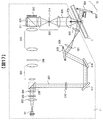
- FIG. 3 shows the recording principle in an example of the basic optical system configuration of the pickup 11 in the optical information recording and reproducing apparatus 10.
- the light beam emitted from the light source 301 passes through the collimator lens 302 and is incident on the shutter 303.
- the shutter 303 is open, after the light beam passes through the shutter 303, the light amount ratio of p-polarized light to s-polarized light becomes a desired ratio by the optical element 304 formed of, for example, a half wavelength plate.
- the light enters a PBS (Polarization Beam Splitter) prism 305.
- PBS Polarization Beam Splitter
- the light beam transmitted through the PBS prism 305 acts as a signal light 306, and after the diameter of the light beam is expanded by the beam expander 308, the light beam is transmitted through the phase mask 309, the relay lens 310 and the PBS prism 311 to obtain the spatial light modulator 312.
- the signal light to which information is added by the spatial light modulator 312 is reflected by the PBS prism 311, and propagates through the relay lens 313 and the spatial filter 314. Thereafter, the signal light is condensed on the optical information recording medium 1 by the objective lens 315.
- the light beam reflected by the PBS prism 305 acts as the reference beam 307 and is set to a predetermined polarization direction according to the time of recording or reproduction by the polarization direction conversion element 316, and then galvano via the mirror 317 and the mirror 318.
- the light is incident on the mirror 319.
- the angle of the galvano mirror 319 can be adjusted by the actuator 320, so that the angle of incidence of the reference light incident on the optical information recording medium 1 after passing through the lens 321 and the lens 322 can be set to a desired angle.
- it may replace with a galvano mirror and may use the element which converts the wave front of reference light.
- a hologram corresponding to each reference beam angle will be called a page
- a set of angle-multiplexed pages in the same area will be called a book.
- FIG. 17 shows the principle of reproduction in an example of the basic optical system configuration of the pickup 11 in the optical information recording and reproducing apparatus 10.
- the reference light is made incident on the optical information recording medium 1, and the light beam transmitted through the optical information recording medium 1 is reflected by the galvano mirror 324 whose angle can be adjusted by the actuator 323. By doing this, the reproduction reference light is generated.
- the reproduction light reproduced by the reproduction reference light propagates through the objective lens 315, the relay lens 313, and the spatial filter 314. Thereafter, the reproduction light passes through the PBS prism 311 and is incident on the light detector 325 so that the recorded signal can be reproduced.
- an imaging element such as a CMOS image sensor or a CCD image sensor can be used as the light detector 325, but any element may be used as long as page data can be reproduced.
- phase mask 309 in the present embodiment and the method of driving the same will be described with reference to FIGS. 1, 4 and 5.
- FIG. 1 is a diagram showing the shape of the phase mask 309 and the details of driving.
- the phase mask 309 is provided on the surface perpendicular to the signal light 306 with irregularities that are sufficiently large with respect to the pixel pitch and sufficiently shallow (1% or less) with respect to the wavelength as indicated by 1001 to 1003.
- the phase difference is superimposed on the wavefront of the incident light beam 306 due to the difference in refractive index at the unevenness.
- the surface asperities of the phase mask have a periodic pattern in the y-axis direction in the drawing.
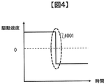
- the driving speed be constant in order to make the phase change in the signal light uniform.
- the time with a constant speed is taken as large as possible, the drive profile shown in FIG. 4 is obtained.
- a rapid change in speed such as 4001 causes vibration due to inertia, and causes deterioration of the device performance including recording and reproduction. Therefore, in the present embodiment, as shown in FIG. 5, a drive profile in which the drive speed smoothly and periodically changes with time is used.
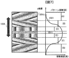
- the drive profile of FIG. 1 is projected in the y-coordinate direction of FIG. 1, the drive profile is as indicated by 1001 in the graph shown on the right of FIG.
- the vertical axis represents the coordinate position of the phase mask in the y direction
- the horizontal axis represents the driving speed of the phase mask.
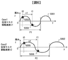
- the phase change speed of the wavefront of the light beam 306 by the phase mask is constant or equal in order to equalize the recording conditions of each pixel in the page and between pages and the number of possible multiple recordings. It is desirable that it is more than fixed. This is equivalent to making the change speed of the surface asperity of the phase mask passing through the light beam 306 constant. A method for realizing this will be described with reference to FIG.
- the upper diagram of FIG. 6 is a diagram when the phase mask is moving at a velocity v1, and while the time changes from t0 to t1, the mask irradiation position moves from 5003 to 5004.
- the period of the mask surface unevenness at this time is P1.
- the lower part of FIG. 3 is a diagram when the phase mask is moving at v2 faster than the velocity v1.
- the period P2 of the mask surface unevenness is given by the following equation (1) Know what to do.
- the change speed of the surface unevenness of the phase mask passing through the light flux 306 can be made constant, and the speed of phase change inside the page of the light flux 306 is constant. can do.
- the speed of phase change of the light beam 306 is fixed for simplification of the description, but depending on the recording and reproduction performance, conditions under which the speed of phase change is equal to or more than a constant or less than a certain value may be considered.
- the speed is set to a certain level or more, the ratio of the unevenness cycle of the mask surface to the driving speed can be realized by adding a restriction so as to satisfy the predetermined condition.
- the drive speed of the phase mask may be changed linearly.
- the concavities and convexities of the phase mask are shown at a fixed period for the sake of simplicity of the description, but it is also considered to randomly arrange the concavities and convexities on the surface of the phase mask in order to make the phase of incident light flux random.
- the unevenness cycle of the mask surface is formed so that the ratio of the minimum value or the average value of the driving speed of the phase mask across the incident light beam at an arbitrary position on the phase mask and the unevenness interval of the mask surface becomes constant. Good.
- the method of adding irregularities to the surface of the phase mask when changing the phase of the light beam 306 has been described, but as a method of changing the phase of the light beam, There is a method of embedding different materials periodically or randomly.
- the present application defines the relationship between the driving speed of the phase mask crossing the incident light beam at an arbitrary position on the phase mask and the phase addition method of the mask surface, and any method for changing the phase of the light beam is limited. is not.
- a third embodiment of the present invention will be described according to the attached drawings.
- the basic optical system structure of the recording and reproducing apparatus 10 of the optical information recording medium of the present embodiment and the pickup 11 is the same as in FIGS. 2 and 3, and the description thereof is omitted here.
- FIG. 7 shows a phase mask in the optical information recording and reproducing apparatus 10 in the present embodiment.
- the phase mask of this embodiment has the same function as that of the first embodiment of the present invention.
- the concavo-convex cycle of the mask surface is changed as shown in the right side of FIG.
- the relationship between the change of the unevenness cycle of the mask surface and the moving speed is the same as that of the first embodiment of the present invention.
- the recording and reproducing apparatus 10 of the optical information recording medium of the present embodiment is the same as that of FIG. 2, and the description thereof is omitted here.
- FIG. 8 shows the recording principle in an example of the basic optical system configuration of the pickup 11 in the optical information recording / reproducing apparatus 10 of this embodiment.
- the principle of the first embodiment of the present invention Elements having the same functions as those in FIG. 3 are indicated by the same reference numerals, and the description thereof is omitted here.
- reference numeral 6309 denotes a phase mask having a disk shape, and has a mechanism that rotates about a shaft 6001 in a plane perpendicular to the light beam 306. The details are shown in FIG.
- the phase mask 6309 has projections and depressions sufficiently large (relative to the pixel pitch) and sufficiently shallow (1% or less) with respect to the wavelength on the surface of the phase mask periodically in the circumferential direction. It shall be arranged.
- the surface asperities of the phase mask have periodic patterns in the circumferential direction of rotation at each radial position.
- reference numeral 6002 denotes a phase mask pattern at a radial position r1 around the rotation axis 6001 of the phase mask 6309
- 6003 denotes a phase mask pattern at a radial position r2.
- the linear velocity vr1 in the circumferential direction at the radial position r1 under the condition that the phase mask 6309 is rotating at the rotational angular velocity ⁇ is expressed by Expression (2).
- the unevenness cycle of the phase mask pattern 6002 at this time is set to Pr1.
- the linear velocity varies depending on the radial position.
- the speed of phase change in the page of the light beam 306 is constant. Or, it is desirable to make it a certain value or more.
- the asperity period Pr2 of the phase mask pattern 6003 at the radial position r2 is expressed by the following equation (4).
- the ratio of the linear velocity across the incident light beam at an arbitrary radial position of the phase mask to the irregular period of the mask surface at the radial position is constant.
- Form an asperity cycle Since the change of the driving speed vr of the phase mask is expressed as a function of the displacement r in the radial direction of the phase mask, the change of the period P of the unevenness of the surface of the phase mask is also a function of the radial direction r of the phase mask.
- the shape of the phase mask is a disk shape in the above embodiment, the shape is not necessarily limited to the above.
- phase change speed of the light beam 306 the change of the drive speed of the phase mask, the random arrangement of the concavities and convexities on the surface of the phase mask, and the method of adding the phase change to the light beam 306 are the same as those of the first embodiment. It is not limited to the content of.
- a fourth embodiment of the present invention will be described in accordance with the attached drawings.
- the recording and reproducing apparatus 10 of the optical information recording medium of the present embodiment is the same as that of FIG. 2, and the description thereof is omitted here.
- FIG. 10 shows the recording principle in an example of the basic optical system configuration of the pickup 11 in the optical information recording / reproducing apparatus 10 of this embodiment.
- the principle of the first embodiment of the present invention Elements having the same functions as those in FIG. 3 are indicated by the same reference numerals, and the description thereof is omitted here.
- the difference from FIG. 3 is that the phase mask 309 is eliminated and an optical filter 8001 is provided in the vicinity of the spatial filter 314.
- a Fourier image similar to the Fourier image recorded on the medium is formed by the relay lens 313, and the size of the Fourier image is recorded on the medium by limiting the size of the Fourier image with the aperture of the spatial filter 314.
- FIG. 9001 indicates the Nyquist region
- 9002 indicates the zero-order light region
- 9003 indicates the aperture region of the spatial filter 314.
- Signal light used for recording information on a medium is a light flux in the area 9003 in the figure.
- a schematic view of the light intensity distribution in the opening region of the spatial filter 314 is shown in FIG.
- the light intensity usually becomes stronger as it goes to the center within the zero light region, that is, as it becomes a DC component.
- the portion with high light intensity consumes more media at the time of information recording to the media, leading to a decrease in the number of recordable multiplexes in angle multiplex recording.
- the portion with high light intensity is smoothed to secure the number of recordable multiplexes.
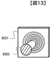
- An optical filter 8001 of this embodiment is shown in FIG.
- the center of the filter is processed so that the transmittance changes concentrically as indicated by 12001, and the light beam 8002 is input so that the optical axis is aligned with this central portion.
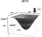
- the transmittance distribution of the above filter is shown in FIG.
- the axis A and the axis B in the figure represent the coordinates of the plane on which the signal light is incident, and the optical axis is incident in the direction of the arrow 12001.
- the axis C represents the light transmittance at each coordinate position.
- the light transmittance distribution 12003 is processed such that the central portion of the filter, that is, the so-called DC portion has the lowest transmittance as shown in the figure.
- the drive portion since the intensity is directly controlled to the same distribution as the light intensity distribution in the medium at the time of recording, the drive portion is not required as in the embodiments 1 and 2 of the present invention. Therefore, as in the first and second embodiments of the present invention, while achieving an increase in the number of recording multiplexes and stable recording by equalization of the media consumption in angle multiplex recording, the drive portion inside the apparatus is improved with respect to the first and second embodiments. It is possible to reduce the volume and suppress the vibration generated from the drive part.
- the spectrum variable mask 8001 is disposed closer to the spatial modulator of the spatial filter 314, but may be disposed closer to the objective lens.
- the function of the spectrum variable mask 8001 may be added to the spatial filter 314 to integrate them.
- the aperture of the spatial filter 314 is provided with a mechanism for changing the transmittance distribution of the spectrum variable mask 8001.
- the light intensity of the DC portion in the above optical filter can be suppressed by the same method as described above also for peak frequency regions other than DC.
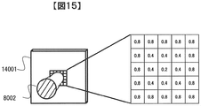
- FIG. 15 is a diagram of an optical filter having the same function as the optical filter 8001 of the third embodiment of the present invention.
- the configuration of the recording / reproducing apparatus and the optical system configuration are the same as those of the third embodiment except that the optical filter 14001 of the same figure is used instead of the optical filter 8001 in this embodiment, and the description will be omitted here. .
- the difference between the filter 14001 and the above 8001 is that the filter shown in the figure can change the transmittance for each area.
- the filter surface is divided into 5 ⁇ 5 regions, and the transmittance can be set individually for each region.
- a method of realizing the above configuration a method of using a liquid crystal element which can be controlled from the outside can be considered.
- the numerical distribution of light transmittance is indicated by an example of a 5 ⁇ 5 matrix, but the configuration for realizing the transmittance distribution, the decomposition number of the matrix, and the like are not limited to the present embodiment. .
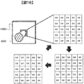
- FIG. 16 is a diagram of an optical filter according to a sixth embodiment of the present invention.
- the configuration of the recording / reproducing apparatus of this embodiment and the configuration of the optical system are the same as those of the fourth embodiment, and the description thereof is omitted here.
- the difference between this embodiment and the fourth embodiment is that the transmittance is changed for each area of the optical filter 14001 during recording, that is, the light transmittance distribution of the optical filter 14001 is changed.
- FIG. 16 shows an example of changing to three different light transmittance distributions. This configuration makes it possible to more uniformly disperse the light intensity distribution in an arbitrary region of the Fourier image in the vicinity of the spatial filter 314, and realizes an increase in the number of multiplexed recordings and stable recording by equalizing media consumption in angle multiplex recording. can do.
- the configuration for realizing the transmittance distribution, and the decomposition number of the matrix which are shown in the example of the row and the column number configuration of the light transmittance matrix, etc. Is not limited to this embodiment.
- the intensity distribution of the signal light is controlled by the transmittance distribution of the optical filter to suppress the region where the light intensity is strong, thereby reducing the light intensity of the entire signal light. And deterioration of the signal reproduction performance due to the lack of the DC component.
- An optical information recording medium recording / reproducing apparatus for recording and / or reproducing digital information using holography in the present embodiment is the same as the recording / reproducing apparatus in FIG. 9 of the fourth embodiment of the present invention. I omit explanation.
- FIG. 18 is a block diagram of the signal processing circuit 85 of the optical information recording and reproducing apparatus 10. As shown in FIG.
- the controller 89 instructs the signal processing circuit 85 to reproduce data of one page input from the pickup 11.
- the processing instruction from the controller 89 is notified to the sub controller 801 in the signal processing circuit 85 via the control line 811.
- the sub controller 801 controls each signal processing circuit via the control line 811 to operate each signal processing circuit in parallel.
- the memory control circuit 803 is controlled to store image data input from the pickup 11 via the pickup interface circuit 810 in the memory 802 via the data line 812.
- the image position detection circuit 809 performs control to detect a marker from the image data stored in the memory 802 and extract an effective data range.
- the image distortion correction circuit 808 performs distortion correction such as inclination, magnification, and distortion of the image, and controls to convert the image data into an expected two-dimensional data size.
- Each bit data of a plurality of bits making up the size converted two-dimensional data is binarized to determine “0” or “1” in the binarization circuit 807, and the data is arranged in the memory 802 by the output data of the reproduction data. Control to store.
- an error correction circuit 806 corrects an error contained in each data string
- a descrambling circuit 805 descrambles adding a pseudo random number data string
- a CRC operation circuit 804 causes an error in user data on the memory 802. Make a confirmation not included. Thereafter, the user data is transferred from the memory 802 to the input / output control circuit 90.
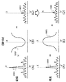
- FIG. 19A shows the light intensity distribution of a light beam incident on the optical filter 8001 of FIG. 10, where the horizontal axis represents the spatial position of the plane perpendicular to the light beam, and the vertical axis represents the light intensity.
- the irradiation surface of the light flux is two-dimensional, it is expressed in one dimension here for the sake of simplicity.
- XX ′ in the figure indicates the center of the luminous flux 8002.
- FIG. 19B is a graph showing the transmittance characteristics of the optical filter 8001. The horizontal axis represents the spatial position of the plane perpendicular to the light flux, and the vertical axis represents the light transmittance.
- FIG. 19C shows the light intensity distribution of the light flux 8003 obtained by passing the light flux 8002 through FIG.
- the horizontal axis and the vertical axis are the same as (A) in the figure.
- the optical filter 8001 by passing through the optical filter 8001, information can be recorded on the medium by the light intensity distribution smoothed by lowering the intensity near the center of the intensity distribution, that is, near DC, and multiplexing in angle multiplex recording An increase in the number can be realized.
- FIG. 19D shows the charge intensity distribution of the reproduced image obtained by the photodetector 325 of FIG.
- the horizontal axis in the figure is the spatial frequency of the reproduced image plane, and the vertical axis is the charge intensity obtained from the light detector.
- FIG. 19E is an electrical filter having the inverse characteristic of the optical filter of FIG. 19B, which is mounted on the image distortion correction circuit 808 of FIG.
- the horizontal axis of the figure shows the spatial frequency of the input image plane, and the vertical axis shows the amplifier gain.
- an increase in the number of recording multiplexes is realized by equalization of media consumption in angle multiplex recording, and the signal strength of the reproduced image at the time of information reproduction from the medium is secured. Stable reproduction performance can be secured.
- the present invention is not limited to the embodiments described above, but includes various modifications.
- the embodiments described above are described in detail in order to explain the present invention in an easy-to-understand manner, and are not necessarily limited to those having all the configurations described.
- part of the configuration of one embodiment can be replaced with the configuration of another embodiment, and the configuration of another embodiment can be added to the configuration of one embodiment.
- control lines and information lines indicate what is considered to be necessary for the description, and not all control lines and information lines in the product are necessarily shown. In practice, almost all configurations may be considered to be mutually connected.
Landscapes
- Physics & Mathematics (AREA)
- Optics & Photonics (AREA)
- Chemical & Material Sciences (AREA)
- Crystallography & Structural Chemistry (AREA)
- General Physics & Mathematics (AREA)
- Optical Recording Or Reproduction (AREA)
- Optical Head (AREA)
Abstract
Description
この場合、特許文献2記載の効果を得ながらページ内部、ページ間の各画素の記録条件を等しくするため、ページ内部、ページ間の位相変化の速度は一定、もしくは一定以上であることが望ましい。しかし、特許文献2記載の位相マスクの駆動方法では、上記内容については考慮されていない、という課題がある。
図3の下図は位相マスクが速度v1より速いv2で移動している際の図である。このときのマスク照射位置の5005、5006への変化によるマスク厚み方向の変化を、上図の5003、5004と同じとするには、マスク表面凹凸の周期P2を以下の式(1)のようにすればよいことがわかる。

関係は本発明の第1の実施例と同様である。
容易にしつつ、略同様の効果を得ることができる。


上記を実現するには、半径位置r2での位相マスクパターン6003の凹凸周期Pr2を以下の式(4)に示すようにする。

なお、位相マスクの駆動速度vrの変化が位相マスクの半径方向の変位rの関数であらわされるため、位相マスクの表面の凹凸の周期Pの変化も位相マスクの半径方向rの関数となる。
ページ内部、ページ間の各画素の記録条件を等しくすることができ、安定した記録性能を確保することができる。
本実施例では光学フィルタ8001の代わりに同図の光学フィルタ14001を使用する点以外は、記録再生装置の構成、および光学系構成とも第3の実施例と同様であり、ここでは説明を省略する。
本構成により、空間フィルタ314近傍のフーリエ像の任意の領域の光強度の強い部分を抑圧することが可能になる。これにより、フーリエ像のDC部分以外に発生した光強度の強い部分についても、強度を抑圧し、角度多重記録におけるメディア消費の均一化による記録多重数増加と安定した記録を実現することができる。上記構成を実現させる方法としては、外部から制御が可能な液晶素子を用いる方法などが考えられる。
本実施例の記録再生装置の構成、および光学系構成とも第4の実施例と同様であり、ここでは説明を省略する。
本実施例と第4の実施例との相違は、記録中に光学フィルタ14001の領域毎に透過率を変化、すなわち光学フィルタ14001の光透過率分布を変化させる点である。図16では異なる3種類の光透過率分布に変化させる例を示す。
本構成により、空間フィルタ314近傍のフーリエ像の任意の領域の光強度の分布をより均一に散らすことが可能となり、角度多重記録におけるメディア消費の均一化による記録多重数増加と安定した記録を実現することができる。
図18は、光情報記録再生装置10の信号処理回路85のブロック図である。
図19(A)は図10の光学フィルタ8001に入射する光束の光強度分布を示す図であり、横軸が光束に垂直な面の空間位置、縦軸が光強度を示す。光束の照射面は2次元であるが、ここでは図示を簡単にするため、1次元で表現する。図のX-X‘は光束8002の中心を示す。図19(B)は光学フィルタ8001の透過率特性を示す図であり、横軸が光束に垂直な面の空間位置、縦軸が光透過率を示す。(A)同様に図のX-X‘が光束8002の中心を示す。
図19(C)は光束8002を同図の(B)に通して得られる光束8003の光強度分布を示す。横軸、縦軸は同図の(A)と同様である。
12・・・再生用参照光光学系、13・・・ディスクCure光学系、
14・・・ディスク回転角度検出用光学系、81・・・アクセス制御回路、
82・・・光源駆動回路、83・・・サーボ信号生成回路、
84・・・サーボ制御回路、85・・・信号処理回路、86・・・信号生成回路、
87・・・シャッタ制御回路、88・・・ディスク回転モータ制御回路、
89・・・コントローラ、90…入出力制御回路、91…外部制御装置、
301・・・光源、303・・・シャッタ、306・・・信号光、307・・・参照光、
308・・・ビームエキスパンダ、309、6309・・フェーズ(位相)マスク、
310・・・リレーレンズ、311・・・PBSプリズム、
312・・・空間光変調器、313・・・リレーレンズ、314・・・空間フィルタ、
315・・・対物レンズ、316・・・偏光方向変換素子、320・・・アクチュエータ、
321・・・レンズ、322・・・レンズ、323・・・アクチュエータ、
324・・・ミラー、325・・・光検出器
501・・・光源、502・・・コリメートレンズ、503・・・シャッタ、504・・・光学素子、
505・・・PBSプリズム、506・・・信号光、507・・・PBSプリズム、508・・・空間光変調器、
509・・・アングルフィルタ、510・・・対物レンズ、511・・・対物レンズアクチュエータ、
512・・・参照光、513・・・ミラー、514・・・ミラー、515・・・レンズ、
516・・・ガルバノミラー、517・・・アクチュエータ、518・・・光検出器、
519・・・偏光方向変換素子、520・・・駆動方向、521・・・光学ブロック、
8001、14001・・・光学フィルタ
Claims (12)
- 2次元のページデータを光情報記録媒体に複数記録する光情報記録装置において、
光ビームを発射する光源と、
前記光ビームを参照光と信号光に分離する偏光ビームスプリッタと、
前記信号光に位相情報を付加する位相マスクと
前記参照光と前記信号光を前記光情報記録媒体に照射し、両光を干渉させて情報を記録するレンズと、を備え、
前記位相マスクは信号光の照射面に凹凸を具備し、
前記照射面の所定の方向の位置座標をyとするとき、
前記凹凸の周期、または凹凸の最小間隔がyの関数となる
ことを特徴とする光情報記録装置。 - 請求項1記載の光情報記録装置であって、
前記位相マスクの所定の位置からの距離をrとするとき、
前記凹凸の周期、または凹凸の最小間隔がrの関数となる
ことを特徴とする光情報記録装置。 - 請求項2記載の光情報記録装置において、
前記位相マスクは信号光照射面に垂直な方向に軸を持つ回転運動をする
ことを特徴とする光情報記録装置。 - 2次元のページデータを光情報記録媒体に複数記録する光情報記録装置において、
光ビームを発射する光源と、
前記信号光に位相情報を付加する位相マスクと
前記参照光と前記信号光を前記光情報記録媒体に照射し、両光を干渉させて情報を記録するレンズを備え、
前記光情報記録媒体に少なくとも2ページ以上の異なるページのデータを記録する際に、
前記位相マスクを前期信号光の光軸と垂直な方向に速度を変化させて移動させる
ことを特徴とする光情報記録装置。 - 請求項4記載の光情報記録装置において、
前記位相マスクは信号光の照射面に凹凸を具備し、
前記位相マスクを前期信号光の光軸と垂直な方向に速度を変化させて移動させるときに
前記位相マスクの信号光照射面における凹凸の高さの変化の速度が所定値である
ことを特徴とする光情報記録装置。 - 請求項4記載の光情報記録装置において、
前記位相マスクの移動速度の変化、もしくは移動方向の変化のいずれか一方、もしくは両方が
周期的に変化する
ことを特徴とする光情報記録装置。 - 請求項4記載の光情報記録装置において、
前記位相マスクの移動速度の変化が線形である
ことを特徴とする光情報記録装置。 - 請求項4記載の光情報記録装置において、
前記位相マスクの移動速度の変化が非線形である
ことを特徴とする光情報記録装置。 - 2次元のページデータを光情報記録媒体に複数記録する光情報記録装置において、
光ビームを発射する光源と、
前記光ビームを参照光と信号光に分離する偏光ビームスプリッタと、
前記信号光のフーリエ像のサイズを制限する空間フィルタと
光透過率を変化させて前記信号光のフーリエ像の輝度分布を変化させる光学フィルタと
前記光学フィルタを制御するコントローラと
前記参照光と前記信号光を前記光情報記録媒体に照射し、両光を干渉させて情報を記録するレンズを具備する
ことを特徴とする光情報記録装置。 - 請求項9記載の光情報記録装置であって、
前記光情報記録媒体に参照光を照射して得られる回折された信号光を検出する光検出器と
前記光検出器から出力されるページデータの信号強度の輝度を補正する信号処理フィルタを
具備し、
前記信号処理フィルタは前記光学フィルタによるページデータの信号強度の劣化を補償する
ことを特徴とする光情報記録再生装置。 - 請求項9記載の光情報記録装置であって、
前記光学フィルタに通過させることにより、前記信号光の光軸と垂直な面における光強度分布を変化させる
ことを特徴とする、光情報記録方法および前記方法を適用した光情報記録装置。 - 請求項11記載の光情報記録装置において、
前記光学フィルタの有する光透過率分布により
前記信号光の光軸と垂直な面における光強度分布を変化させる
ことを特徴とする、光情報記録方法および前記方法を適用した光情報記録装置。
Priority Applications (4)
| Application Number | Priority Date | Filing Date | Title |
|---|---|---|---|
| US14/443,117 US9330704B2 (en) | 2012-11-19 | 2012-11-19 | Optical information recording device, optical information recording and reproducing device, optical information recording method, optical information recording and reproducing method, and optical element |
| CN201280077048.1A CN104798134B (zh) | 2012-11-19 | 2012-11-19 | 光信息记录装置、光信息记录再现装置、光信息记录方法、光信息记录再现方法、和光学元件 |
| PCT/JP2012/079891 WO2014076830A1 (ja) | 2012-11-19 | 2012-11-19 | 光情報記録装置、光情報記録再生装置、光情報記録方法、光情報記録再生方法、及び光学素子 |
| JP2014546817A JP6158213B2 (ja) | 2012-11-19 | 2012-11-19 | 光情報記録装置、光情報記録再生装置、光情報記録方法、光情報記録再生方法、及び光学素子 |
Applications Claiming Priority (1)
| Application Number | Priority Date | Filing Date | Title |
|---|---|---|---|
| PCT/JP2012/079891 WO2014076830A1 (ja) | 2012-11-19 | 2012-11-19 | 光情報記録装置、光情報記録再生装置、光情報記録方法、光情報記録再生方法、及び光学素子 |
Publications (1)
| Publication Number | Publication Date |
|---|---|
| WO2014076830A1 true WO2014076830A1 (ja) | 2014-05-22 |
Family
ID=50730770
Family Applications (1)
| Application Number | Title | Priority Date | Filing Date |
|---|---|---|---|
| PCT/JP2012/079891 Ceased WO2014076830A1 (ja) | 2012-11-19 | 2012-11-19 | 光情報記録装置、光情報記録再生装置、光情報記録方法、光情報記録再生方法、及び光学素子 |
Country Status (4)
| Country | Link |
|---|---|
| US (1) | US9330704B2 (ja) |
| JP (1) | JP6158213B2 (ja) |
| CN (1) | CN104798134B (ja) |
| WO (1) | WO2014076830A1 (ja) |
Cited By (1)
| Publication number | Priority date | Publication date | Assignee | Title |
|---|---|---|---|---|
| JP2017091594A (ja) * | 2015-11-06 | 2017-05-25 | 日本放送協会 | 空間フィルターおよびそれを用いたホログラム記録装置 |
Families Citing this family (9)
| Publication number | Priority date | Publication date | Assignee | Title |
|---|---|---|---|---|
| WO2014076830A1 (ja) * | 2012-11-19 | 2014-05-22 | 日立コンシューマエレクトロニクス株式会社 | 光情報記録装置、光情報記録再生装置、光情報記録方法、光情報記録再生方法、及び光学素子 |
| GB2578236B (en) | 2017-05-24 | 2022-11-09 | Univ Columbia | Broadband achromatic flat optical components by dispersion-engineered dielectric metasurfaces |
| EP3676973A4 (en) | 2017-08-31 | 2021-05-05 | Metalenz, Inc. | INTEGRATION OF LENS WITH PERMEABLE METAL SURFACE |
| EP4729996A2 (en) | 2018-01-24 | 2026-04-22 | President And Fellows Of Harvard College | Polarization state generation with a metasurface |
| KR102869686B1 (ko) | 2018-07-02 | 2025-10-14 | 메탈렌츠 인코포레이티드 | 레이저 스펙클 감소를 위한 메타표면들 |
| CN114286953B (zh) | 2019-07-26 | 2025-04-01 | 梅特兰兹股份有限公司 | 孔隙-超表面和混合折射-超表面成像系统 |
| US11578968B1 (en) | 2019-10-31 | 2023-02-14 | President And Fellows Of Harvard College | Compact metalens depth sensors |
| EP4348780A4 (en) | 2021-05-25 | 2025-04-23 | Metalenz, Inc. | Single element dot pattern projector |
| WO2024205646A2 (en) | 2022-03-31 | 2024-10-03 | Metalenz, Inc. | Polarization sorting metasurface microlens array device |
Citations (3)
| Publication number | Priority date | Publication date | Assignee | Title |
|---|---|---|---|---|
| JPH07104647A (ja) * | 1993-10-05 | 1995-04-21 | Nikon Corp | ホログラム形成方法及び装置 |
| JP2000121820A (ja) * | 1998-10-19 | 2000-04-28 | Oki Electric Ind Co Ltd | 光ファイバグレーティングの作製方法 |
| JP2006343533A (ja) * | 2005-06-09 | 2006-12-21 | Sony Corp | ホログラム装置及びインコヒーレント光生成方法 |
Family Cites Families (15)
| Publication number | Priority date | Publication date | Assignee | Title |
|---|---|---|---|---|
| US6569600B2 (en) * | 2001-03-30 | 2003-05-27 | Eastman Kodak Company | Optical recording material |
| US7023562B2 (en) * | 2001-09-10 | 2006-04-04 | Zygo Corporation | Characterization of period variations in diffraction gratings |
| US7092133B2 (en) | 2003-03-10 | 2006-08-15 | Inphase Technologies, Inc. | Polytopic multiplex holography |
| JP4162518B2 (ja) * | 2003-03-17 | 2008-10-08 | Tdk株式会社 | ホログラム記録再生方法及びホログラム記録媒体 |
| KR100845565B1 (ko) * | 2003-12-01 | 2008-07-10 | 더 보드 오브 트러스티즈 오브 더 유니버시티 오브 일리노이 | 나노스케일 3차원 구조물의 제조방법 및 장치 |
| US7813017B2 (en) * | 2005-10-21 | 2010-10-12 | Inphase Technologies, Inc. | Method and system for increasing holographic data storage capacity using irradiance-tailoring element |
| JP4696890B2 (ja) * | 2005-12-12 | 2011-06-08 | 富士ゼロックス株式会社 | ホログラム記録方法及びホログラム記録装置 |
| KR20080103147A (ko) * | 2007-05-23 | 2008-11-27 | 주식회사 대우일렉트로닉스 | 페이즈 쉬프트 마스크, 페이즈 쉬프트 마스크 제조방법 |
| JP2009037685A (ja) * | 2007-08-01 | 2009-02-19 | Sony Corp | ホログラム記録再生装置 |
| JP5211816B2 (ja) * | 2008-04-11 | 2013-06-12 | 株式会社日立製作所 | 光情報記録再生装置 |
| US20090268595A1 (en) * | 2008-04-25 | 2009-10-29 | Tdk Corporation | Information recording medium and recording/reproducing apparatus |
| JP2010164832A (ja) * | 2009-01-16 | 2010-07-29 | Sony Corp | 光照射装置、光照射方法 |
| JP5557787B2 (ja) * | 2011-04-06 | 2014-07-23 | 日立コンシューマエレクトロニクス株式会社 | 光情報再生装置、光情報記録再生装置 |
| EP2562568B1 (en) * | 2011-08-23 | 2014-06-25 | SICK STEGMANN GmbH | Fabrication method of cylindrical gratings |
| WO2014076830A1 (ja) * | 2012-11-19 | 2014-05-22 | 日立コンシューマエレクトロニクス株式会社 | 光情報記録装置、光情報記録再生装置、光情報記録方法、光情報記録再生方法、及び光学素子 |
-
2012
- 2012-11-19 WO PCT/JP2012/079891 patent/WO2014076830A1/ja not_active Ceased
- 2012-11-19 US US14/443,117 patent/US9330704B2/en not_active Expired - Fee Related
- 2012-11-19 CN CN201280077048.1A patent/CN104798134B/zh not_active Expired - Fee Related
- 2012-11-19 JP JP2014546817A patent/JP6158213B2/ja not_active Expired - Fee Related
Patent Citations (3)
| Publication number | Priority date | Publication date | Assignee | Title |
|---|---|---|---|---|
| JPH07104647A (ja) * | 1993-10-05 | 1995-04-21 | Nikon Corp | ホログラム形成方法及び装置 |
| JP2000121820A (ja) * | 1998-10-19 | 2000-04-28 | Oki Electric Ind Co Ltd | 光ファイバグレーティングの作製方法 |
| JP2006343533A (ja) * | 2005-06-09 | 2006-12-21 | Sony Corp | ホログラム装置及びインコヒーレント光生成方法 |
Cited By (1)
| Publication number | Priority date | Publication date | Assignee | Title |
|---|---|---|---|---|
| JP2017091594A (ja) * | 2015-11-06 | 2017-05-25 | 日本放送協会 | 空間フィルターおよびそれを用いたホログラム記録装置 |
Also Published As
| Publication number | Publication date |
|---|---|
| US20150294681A1 (en) | 2015-10-15 |
| US9330704B2 (en) | 2016-05-03 |
| JPWO2014076830A1 (ja) | 2017-01-05 |
| CN104798134B (zh) | 2017-06-09 |
| JP6158213B2 (ja) | 2017-07-05 |
| CN104798134A (zh) | 2015-07-22 |
Similar Documents
| Publication | Publication Date | Title |
|---|---|---|
| JP6158213B2 (ja) | 光情報記録装置、光情報記録再生装置、光情報記録方法、光情報記録再生方法、及び光学素子 | |
| JP5358530B2 (ja) | 光情報記録再生装置及び再生装置 | |
| JP5081741B2 (ja) | 光情報記録装置、光情報記録方法、光情報記録再生装置および光情報記録再生方法 | |
| CN102280115B (zh) | 光信息再现装置、光信息记录装置和光信息记录再现装置 | |
| JP5037391B2 (ja) | 光ピックアップ、光情報記録再生装置および光学的情報記録再生方法 | |
| US20120188618A1 (en) | Optical information reproducing method and optical information reproducing apparatus | |
| CN102385874B (zh) | 再现装置和再现方法 | |
| JP4881914B2 (ja) | 光情報記録再生装置及び光情報記録方法 | |
| JP4961386B2 (ja) | 光情報記録装置、光情報記録方法、光情報記録再生装置および光情報記録再生方法 | |
| JP4969558B2 (ja) | 光情報再生装置、光情報記録再生装置 | |
| JP2011238317A (ja) | 光情報再生装置および光情報再生方法 | |
| WO2013175525A1 (ja) | 光情報記録再生装置、記録条件調整方法及び光情報記録媒体 | |
| JP5104695B2 (ja) | 情報記録装置 | |
| JP5557787B2 (ja) | 光情報再生装置、光情報記録再生装置 | |
| JP5238209B2 (ja) | 光情報記録再生装置とその方法および光情報記録媒体 | |
| JP5049988B2 (ja) | 信号品質評価装置、信号品質評価方法、および情報記録媒体 | |
| JP5517912B2 (ja) | 光情報記録再生方法、及び光情報記録再生装置 | |
| WO2013160927A1 (ja) | 光情報記録再生装置、および光情報記録再生方法、および再生装置 | |
| WO2016143726A1 (ja) | ホログラム記録再生装置、及びホログラム記録再生方法 | |
| JP5953284B2 (ja) | 光情報記録媒体、光情報記録装置、光情報記録方法、光情報再生装置、光情報再生方法。 | |
| JP5414861B2 (ja) | 光情報記録装置、光情報記録方法、光情報記録再生装置および光情報記録再生方法 | |
| JP5640033B2 (ja) | 光情報記録装置、光情報記録方法、光情報記録再生装置および光情報記録再生方法 | |
| WO2012160733A1 (ja) | 光情報記録再生装置および光情報記録再生方法 | |
| JP2017004576A (ja) | 光情報記録再生装置および光情報記録再生方法 | |
| JP2009252339A (ja) | 光情報記録再生装置 |
Legal Events
| Date | Code | Title | Description |
|---|---|---|---|
| 121 | Ep: the epo has been informed by wipo that ep was designated in this application |
Ref document number: 12888268 Country of ref document: EP Kind code of ref document: A1 |
|
| ENP | Entry into the national phase |
Ref document number: 2014546817 Country of ref document: JP Kind code of ref document: A |
|
| WWE | Wipo information: entry into national phase |
Ref document number: 14443117 Country of ref document: US |
|
| NENP | Non-entry into the national phase |
Ref country code: DE |
|
| 122 | Ep: pct application non-entry in european phase |
Ref document number: 12888268 Country of ref document: EP Kind code of ref document: A1 |