WO2014073476A1 - 空気調和システム - Google Patents
空気調和システム Download PDFInfo
- Publication number
- WO2014073476A1 WO2014073476A1 PCT/JP2013/079690 JP2013079690W WO2014073476A1 WO 2014073476 A1 WO2014073476 A1 WO 2014073476A1 JP 2013079690 W JP2013079690 W JP 2013079690W WO 2014073476 A1 WO2014073476 A1 WO 2014073476A1
- Authority
- WO
- WIPO (PCT)
- Prior art keywords
- air
- air conditioner
- detection result
- reference value
- conditioning system
- Prior art date
- Legal status (The legal status is an assumption and is not a legal conclusion. Google has not performed a legal analysis and makes no representation as to the accuracy of the status listed.)
- Ceased
Links
Images






Classifications
-
- B—PERFORMING OPERATIONS; TRANSPORTING
- B60—VEHICLES IN GENERAL
- B60H—ARRANGEMENTS OF HEATING, COOLING, VENTILATING OR OTHER AIR-TREATING DEVICES SPECIALLY ADAPTED FOR PASSENGER OR GOODS SPACES OF VEHICLES
- B60H1/00—Heating, cooling or ventilating devices
- B60H1/00642—Control systems or circuits; Control members or indication devices for heating, cooling or ventilating devices
- B60H1/00735—Control systems or circuits characterised by their input, i.e. by the detection, measurement or calculation of particular conditions, e.g. signal treatment, dynamic models
- B60H1/008—Control systems or circuits characterised by their input, i.e. by the detection, measurement or calculation of particular conditions, e.g. signal treatment, dynamic models the input being air quality
-
- B—PERFORMING OPERATIONS; TRANSPORTING
- B60—VEHICLES IN GENERAL
- B60H—ARRANGEMENTS OF HEATING, COOLING, VENTILATING OR OTHER AIR-TREATING DEVICES SPECIALLY ADAPTED FOR PASSENGER OR GOODS SPACES OF VEHICLES
- B60H3/00—Other air-treating devices
- B60H3/0071—Electrically conditioning the air, e.g. by ionizing
- B60H3/0078—Electrically conditioning the air, e.g. by ionizing comprising electric purifying means
-
- F—MECHANICAL ENGINEERING; LIGHTING; HEATING; WEAPONS; BLASTING
- F24—HEATING; RANGES; VENTILATING
- F24F—AIR-CONDITIONING; AIR-HUMIDIFICATION; VENTILATION; USE OF AIR CURRENTS FOR SCREENING
- F24F8/00—Treatment, e.g. purification, of air supplied to human living or working spaces otherwise than by heating, cooling, humidifying or drying
- F24F8/10—Treatment, e.g. purification, of air supplied to human living or working spaces otherwise than by heating, cooling, humidifying or drying by separation, e.g. by filtering
- F24F8/192—Treatment, e.g. purification, of air supplied to human living or working spaces otherwise than by heating, cooling, humidifying or drying by separation, e.g. by filtering by electrical means, e.g. by applying electrostatic fields or high voltages
- F24F8/194—Treatment, e.g. purification, of air supplied to human living or working spaces otherwise than by heating, cooling, humidifying or drying by separation, e.g. by filtering by electrical means, e.g. by applying electrostatic fields or high voltages by filtering using high voltage
-
- F—MECHANICAL ENGINEERING; LIGHTING; HEATING; WEAPONS; BLASTING
- F24—HEATING; RANGES; VENTILATING
- F24F—AIR-CONDITIONING; AIR-HUMIDIFICATION; VENTILATION; USE OF AIR CURRENTS FOR SCREENING
- F24F8/00—Treatment, e.g. purification, of air supplied to human living or working spaces otherwise than by heating, cooling, humidifying or drying
- F24F8/30—Treatment, e.g. purification, of air supplied to human living or working spaces otherwise than by heating, cooling, humidifying or drying by ionisation
-
- F—MECHANICAL ENGINEERING; LIGHTING; HEATING; WEAPONS; BLASTING
- F24—HEATING; RANGES; VENTILATING
- F24F—AIR-CONDITIONING; AIR-HUMIDIFICATION; VENTILATION; USE OF AIR CURRENTS FOR SCREENING
- F24F2110/00—Control inputs relating to air properties
- F24F2110/50—Air quality properties
- F24F2110/65—Concentration of specific substances or contaminants
- F24F2110/66—Volatile organic compounds [VOC]
-
- Y—GENERAL TAGGING OF NEW TECHNOLOGICAL DEVELOPMENTS; GENERAL TAGGING OF CROSS-SECTIONAL TECHNOLOGIES SPANNING OVER SEVERAL SECTIONS OF THE IPC; TECHNICAL SUBJECTS COVERED BY FORMER USPC CROSS-REFERENCE ART COLLECTIONS [XRACs] AND DIGESTS
- Y02—TECHNOLOGIES OR APPLICATIONS FOR MITIGATION OR ADAPTATION AGAINST CLIMATE CHANGE
- Y02A—TECHNOLOGIES FOR ADAPTATION TO CLIMATE CHANGE
- Y02A50/00—TECHNOLOGIES FOR ADAPTATION TO CLIMATE CHANGE in human health protection, e.g. against extreme weather
- Y02A50/20—Air quality improvement or preservation, e.g. vehicle emission control or emission reduction by using catalytic converters
-
- Y—GENERAL TAGGING OF NEW TECHNOLOGICAL DEVELOPMENTS; GENERAL TAGGING OF CROSS-SECTIONAL TECHNOLOGIES SPANNING OVER SEVERAL SECTIONS OF THE IPC; TECHNICAL SUBJECTS COVERED BY FORMER USPC CROSS-REFERENCE ART COLLECTIONS [XRACs] AND DIGESTS
- Y02—TECHNOLOGIES OR APPLICATIONS FOR MITIGATION OR ADAPTATION AGAINST CLIMATE CHANGE
- Y02B—CLIMATE CHANGE MITIGATION TECHNOLOGIES RELATED TO BUILDINGS, e.g. HOUSING, HOUSE APPLIANCES OR RELATED END-USER APPLICATIONS
- Y02B30/00—Energy efficient heating, ventilation or air conditioning [HVAC]
- Y02B30/70—Efficient control or regulation technologies, e.g. for control of refrigerant flow, motor or heating
Definitions
- the present invention relates to an air conditioning system, and more particularly to an air conditioning system including a charged particle generator.
- Patent Document 1 discloses a vehicle ion generator that generates ions according to preset conditions even when the engine is not started. When the vehicle user gets into the vehicle, the vehicle interior can be sterilized and the odor removed.
- the type of charged particles is not limited to ions.
- the electrostatic particle generator that generates electrostatic fine particle water is air. It is provided on the wall of the duct of the harmony machine.
- the degree of sterilization effect required varies depending on the amount of microorganisms floating in the air in the environment. For example, when the number of microorganisms increases, it is necessary to enhance the bactericidal effect.
- the charged particle generator regardless of the amount of microorganisms, the charged particle generator generates a predetermined amount of charged particles.
- An object of the present invention is to provide an air conditioning system capable of adjusting the sterilizing effect of microorganisms according to the amount of microorganisms in the air in the environment.
- An air conditioning system includes an air conditioner, a charged particle generation device, and a microorganism detection device.
- the air conditioner generates an air flow in the environment.
- the charged particle generator generates charged particles and sends the charged particles into the environment by an air flow from an air conditioner.
- the microorganism detection apparatus repeatedly detects the amount of microorganisms floating in the environment.
- the air conditioning system controls the amount of charged particles delivered to the environment according to the detection result of the microorganism detection device.
- the air conditioning system further includes a control device that determines whether the detection result by the microorganism detection device exceeds a predetermined reference value.
- the air conditioner increases the air volume of the airflow when the control device determines that the detection result exceeds a predetermined reference value.
- the air conditioning system further includes a control device that determines whether the detection result by the microorganism detection device exceeds a predetermined reference value.
- the charged particle generation device increases the generation amount of charged particles when the control device determines that the detection result exceeds a predetermined reference value.
- the air conditioner when the air conditioner is cooling in the environment, when the control device determines that the detection result exceeds the reference value, the air conditioner detects the air flow more than before the detection result exceeds the reference value. Increases the air flow and increases the temperature of the air flow.
- the air conditioner when the air conditioner is heating the environment, when the control device determines that the detection result exceeds the reference value, the air conditioner detects that the air flow is higher than before the detection result exceeds the reference value. The air volume of the air is increased and the temperature of the air flow is decreased.
- the sterilizing effect of microorganisms can be adjusted according to the amount of microorganisms in the air in the environment.
- the air conditioning system according to the present invention is applied to a vehicle.
- the application of the air conditioning system according to the present invention is not limited to vehicles.
- FIG. 1 is a schematic diagram showing a configuration of a vehicle including an air conditioning system according to an embodiment of the present invention.
- vehicle 1 is provided with air conditioning system 10 and passenger seat 4 (front seat 41 and rear seat 42).
- the air conditioning system 10 includes an air conditioner 2, an ion generator 23, and a microorganism detection device 5.
- the air conditioner 2 has a function of introducing air from the outside of the vehicle 1, a function of circulating the air in the vehicle interior (inside the environment) 3, and a function of adjusting the temperature and humidity of the vehicle interior 3 by cooling or heating. Have Thereby, the vehicle interior 3 can be maintained in a comfortable state for the user (not shown). More specifically, the air conditioner 2 includes a heat exchanger 21 and a blower 22. A suction port 25 and an air outlet 24 are provided in a front panel of the front seat 41. The blower 22 blows out the air sucked from the suction port 25 from the blower outlet 24. The heat exchanger 21 is provided between the suction port 25 and the air outlet 24 and cools or heats the air sucked from the suction port 25. Thereby, the temperature and humidity of the airflow blown from the blower outlet 24 are adjusted.
- the ion generator 23 is installed, for example, between the blower 22 and the outlet 24 and generates positive ions and negative ions. Therefore, ions are included in the airflow blown out from the outlet 24 during the operation of the ion generator 23. By placing the generated ions on the airflow, the ions can be diffused over a wide area in the vehicle interior 3. The method by which the ion generator 23 generates ions will be described in detail later. Note that the position of the ion generator 23 is not limited to the above position as long as the ions generated by the ion generator 23 can be diffused by the airflow sent from the air conditioner 2.
- the microorganism detection device 5 is installed behind the rear seat 42, for example. Airflow is generated by the air conditioner 2 behind the rear seat 42.
- the microorganism detection device 5 repeatedly detects the amount of microorganisms (floating microorganisms) floating in the air in the passenger compartment 3 (for example, the number of floating microorganisms per unit volume), and the detection result indicating the amount of floating microorganisms is controlled by the control device 6. Output to.
- the method by which the microorganism detection device 5 detects floating microorganisms will be described in detail later.
- the position of the microorganism detection device 5 is not limited to the back of the rear seat 42.
- the microorganism detection device 5 may be provided at a position where an air flow is generated by the air conditioner 2.
- the microorganism detection device 5 may be provided in an air discharge path (not shown) from 3 to the outside of the vehicle 1. Thereby, the microorganisms detection apparatus 5 can detect rapidly the increase / decrease in the quantity of microorganisms.
- the control device 6 compares the detection result from the microorganism detection device 5 with a preset reference value, and controls at least one of the air conditioner 2 and the ion generator 23 based on the comparison result. The control method by the control device 6 will also be described in detail later.
- FIG. 2 is a diagram showing an example of the appearance of the ion generator 23 in the air conditioning system 10 shown in FIG.
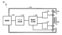
- FIG. 3 is a functional block diagram showing an example of the configuration of the ion generator 23 in the air conditioning system 10 shown in FIG.
- ion generator 23 includes ion generators 23a and 23b and a main body 23c.
- the ion generator 23a and the ion generator 23b have a common structure.
- the ion generators 23a and 23b have induction electrodes 232a and 232b, which are sheet metals with circular holes, and needle-like discharge electrodes 231a and 231b, respectively.
- the tips of the discharge electrodes 231a and 231b are arranged so as to be positioned at the centers of the holes of the induction electrodes 232a and 232b, respectively.
- the main body 23c contains a circuit for applying a high voltage to the ion generators 23a and 23b. More specifically, referring to FIG. 3, the circuit includes a connection unit 233, a signal generation unit 234, a high voltage generation unit 235, a positive polarity high voltage generation unit 236, and a negative polarity high voltage generation unit. 237.
- An external power source (for example, a battery (not shown) of the vehicle 1) is connected to the connection portion 233.
- the signal generation unit 234 receives power from the battery via the connection unit 233 and generates a pulse signal.
- the generated pulse signal is output to the high voltage generator 235.
- the high voltage generation unit 235 uses the pulses from the signal generation unit 234 to generate both positive and negative high voltage pulses.
- the generated high voltage pulse is output to the positive high voltage generator 236 and the negative high voltage generator 237.
- the positive high voltage generator 236 separates the positive high voltage pulse from both the positive and negative high voltage pulses.
- This positive high-voltage pulse is applied to the ion generator 23a, and plasma discharge occurs between the discharge electrode 231a and the induction electrode 232a (see FIG. 2).
- the negative high voltage generator 237 separates the negative high voltage pulse from both the positive and negative high voltage pulses.
- This negative high voltage pulse is applied to the ion generator 23b, and discharge occurs between the discharge electrode 231b and the induction electrode 232b (see FIG. 2).
- negative ions are generated.
- the positive ion is H + (H 2 O) m (m is an arbitrary natural number), and the negative ion is O 2 ⁇ (H 2 O) n (n is an arbitrary natural number).
- H 2 O 2 hydrogen peroxide
- .OH hydroxyl radicals
- the amount of ions delivered from the ion generator 23 to the passenger compartment 3 is adjusted by the control device 6 based on the detection result of the microorganism detection device.
- the following two methods are mainly conceivable.
- the wind speed (or the air volume) passing through the ion generators 23 a and 23 b is increased.
- the concentration of ions (the number of ions per 1 cm 3 ) in the vicinity of the ion generators 23a and 23b is, for example, about several hundred million and is very high.
- most of the generated ions are extinguished immediately after they are generated, attracting and bonding ions of different polarities or adhering to members around the ion generating portions 23a and 23b. Therefore, by increasing the wind speed passing through the ion generators 23a and 23b, the generated ions are immediately moved from the location. Thereby, the annihilation amount of ions decreases. As a result, the amount of ions delivered to the vehicle interior 3 can be increased.
- the voltage value of the high voltage applied to the ion generators 23a and 23b is increased, or the application period of the high voltage is shortened. These are equivalent in that the amount of electric power for generating discharge is increased.
- the amount of ions generated in the ion generators 23a and 23b increases. Therefore, the ion concentration in the vicinity of the ion generating parts 23a and 23b is further increased. Therefore, as in the first method, it is more preferable to immediately move the generated ions from the location by increasing the air volume of the air conditioner 2.
- the ion generator 23 has been described as an example of the “charged particle generator” according to the present invention. However, it is not necessary to limit the “charged particle generator” according to the present invention to the one that generates both positive ions and negative ions like the ion generator 23. Even a device that generates only negative ions is said to have a slight sterilizing effect. In addition, any device that generates charged particles that can provide a bactericidal effect is included in the “charged particle generator” according to the present invention, regardless of the type of the charged particles. For example, the apparatus which sprays electrostatic fine particle water with liquid spraying apparatuses including an electrostatic atomizer may be sufficient. Furthermore, the apparatus which sprays the electrolyzed water produced
- FIG. 4 is a flowchart for explaining a microorganism detection process executed by the microorganism detection apparatus 5 in the air conditioning system 10 shown in FIG.
- the microorganism detection apparatus 5 is configured to detect microorganisms through a process roughly classified into three stages.
- the first stage process is the collection process shown in steps S101 and S102 and FIG.
- the second stage process is the fluorescence measurement process (before and after heating) shown in steps S103 to S108, FIG. 7 and FIG.
- the third stage process is the refresh process shown in steps S109 and S110 and FIG.
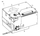
- FIG. 5 is a diagram showing an example of the appearance of the microorganism detection device 5 in the air conditioning system 10 shown in FIG.
- the microorganism detection apparatus 5 includes a main body cabinet 5a and a lower cabinet 5b.
- the main body cabinet 5a is provided with a collection port 5c for collecting floating microorganisms.
- the main body cabinet 5a has a substantially rectangular parallelepiped shape, and has a width of about 5 cm, a depth of about 6 cm, and a height of about 3 cm. Since the microorganism detection device 5 is small, it can be installed inside the air conditioner 2.
- FIG. 6 is a schematic diagram for explaining the principle of the collection step in the flowchart shown in FIG.
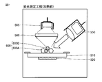
- FIG. 7 is a schematic diagram for explaining the principle of the pre-heating fluorescence measurement step in the flowchart shown in FIG.
- FIG. 8 is a schematic diagram for explaining the principle of the post-heating fluorescence measurement step in the flowchart shown in FIG.
- FIG. 9 is a schematic diagram for explaining the principle of the refresh process in the flowchart shown in FIG.
- a main body cabinet 5a includes a table (collecting unit) 510, a heater 520, a discharge electrode 530, a voltage device 540, a light source 550, a lens 560, and a light receiving unit.
- a unit (detection unit) 565, a brush (refresh unit) 580, and a rotating device (not shown) are provided.
- the rotating device rotates the table 510 around the rotation center (for example, the right end portion of the table 510).
- the table 510 is configured so as to sequentially go through each step shown in the flowchart of FIG.
- a fan 570 is accommodated in the lower cabinet 5b.
- the microorganism detecting device 5 collects the microorganism 600A floating in the air.
- the chemical fiber 600B floating in the air is also collected together (step S101).
- the table 510 is a glass disk with a mirror finish.
- the discharge electrode 530 is a needle-like electrode, and the tip thereof faces the table 510.
- the discharge electrode 530 forms an electric field between the table 510 and the discharge electrode 530 by the voltage supplied from the voltage device 540.
- the suspended matter 600 (microorganism 600A and chemical fiber 600B) is charged.
- the charged suspended matter 600 is adsorbed and collected on the surface of the table 510 maintained at the reference potential.
- the rotating device moves the table 510 to a position for measuring the fluorescence intensity.
- the light source 550 irradiates the collected suspended matter 600 with excitation light such as ultraviolet rays.
- excitation light such as ultraviolet rays.
- the lens 560 collects the fluorescence from the suspended matter 600.
- the light receiving unit 565 receives the fluorescence collected by the lens 560.
- the fluorescence received by the light receiving unit 565 is analyzed by an analysis unit (not shown) (step S103).
- the reason why the surface of the table 510 is mirror-finished is to prevent unnecessary scattered light from being generated in the process of step S103.
- the table 510 that has finished the pre-heating fluorescence measurement is once removed from the position for measuring fluorescence and returned to the collection position in step S101 (step S104).
- step S105 The heater 520 heats the suspended matter 600 collected on the table 510 together with the table 510 (step S105). Thereafter, the fan 570 cools the table 510. (Step S106). In step S107, the rotation device moves the table 510 again to the position for measuring the fluorescence intensity.
- the microorganism 600A and the chemical fiber 600B are irradiated with excitation light again, and the fluorescence is analyzed (step S108). .
- step S105 the microorganism 600A and the chemical fiber 600B are heated at the same time, whereby the microorganism 600A is killed and the chemical fiber 600B is changed in its molecular state. For this reason, the fluorescence changes before and after the heat treatment. Therefore, the amount of the microorganism 600A (for example, the number of microorganisms per unit volume) can be quantitatively evaluated by comparing the fluorescence measurement results before and after the heat treatment.
- the brush 580 cleans the suspended matter 600 on the table 510 (step S109).
- the rotating device returns the table 510 to the collection position (step S110).
- the microorganism detection apparatus 5 does not use an antibody reaction between a microorganism and a specific antibody. Therefore, it is not necessary to prepare an antibody or a medium according to the microorganism to be detected. Therefore, microorganisms can be detected regardless of their type. Moreover, time is not required for reaction (for example, antibody reaction) for detecting microorganisms. Further, when the detection is completed, it can be immediately initialized by the refresh process. Therefore, the microorganism detection apparatus 5 can repeat the processing in steps S101 to S110. That is, the microorganism detection apparatus 5 can continuously detect the floating microorganisms.
- the detection result indicating the amount of airborne microorganisms in the air is output from the microorganism detection device 5 to the control device 6.
- the control device 6 controls at least one of the air conditioner 2 and the ion generator 23 based on the detection result. The control method will be described in detail below.
- FIG. 10 is a flowchart for explaining control by the control device 6 shown in FIG. Referring to FIGS. 1 and 10, for example, the process is started when power to air conditioning system 10 is turned on.
- the air conditioner 2 performs air conditioning (cooling or heating) of the vehicle interior 3.
- step S201 the control device 6 acquires settings of the air conditioner 2 and the ion generator 23.
- step S ⁇ b> 202 the microorganism detection device 5 detects the amount of suspended microorganisms and outputs the detection result to the control device 6.
- the reference value may be determined as a reference range.
- step S204 the amount of suspended microorganisms is less than the reference value. Therefore, the control apparatus 6 controls the air conditioner 2 so that the wind speed of the airflow sent from the air conditioner 2 decreases. Thereby, the electric power which the air conditioner 2 consumes can be reduced.
- step S205 the amount of suspended microorganisms is equal to the reference value. Therefore, the control apparatus 6 controls the air conditioner 2 so that the wind speed of the airflow sent from the air conditioner 2 is maintained. Thereby, the ion concentration of the vehicle interior 3 can be maintained.
- step S206 the amount of airborne microorganisms is larger than the reference value. Therefore, the control apparatus 6 controls the air conditioner 2 so that the wind speed of the airflow sent from the air conditioner 2 increases. As a result, the amount of ions delivered to the passenger compartment 3 increases. Therefore, the floating microorganisms in the passenger compartment 3 can be sterilized and reduced in a shorter time.
- the air conditioner 2 usually gives priority to adjusting the temperature of the passenger compartment 3. Therefore, when the temperature of the vehicle interior 3 rises, the air volume of the airflow from the air conditioner 2 increases to lower the temperature. Along with this, the amount of ions delivered increases. On the other hand, in steps S204 and S205, there is no need to increase the amount of ions delivered. However, even if the ion concentration in the passenger compartment 3 increases, there is no inconvenience for the user. Therefore, there is no problem even if the air conditioner 2 gives priority to the adjustment of the temperature of the passenger compartment 3.
- step S207 the control device 6 compares the difference value between the temperature in the passenger compartment 3 and the set temperature of the air conditioner 2 with a predetermined reference value. If the difference value is greater than or equal to the reference value, the process proceeds to step S208 (“ ⁇ ” in step S207). On the other hand, if the difference value is less than the reference value, the process proceeds to step S209 (“ ⁇ ” in step S207).
- step S208 the temperature in the passenger compartment 3 is not sufficiently lowered as compared with the set temperature of the air conditioner 2. Therefore, the control device 6 gives priority to lowering the temperature of the vehicle interior 3. That is, the control device 6 controls the air conditioner 2 so that the temperature of the airflow sent from the air conditioner 2 is maintained compared to before the detection result by the microorganism detection device 5 exceeds the reference value.
- step S209 the temperature of the passenger compartment 3 is lowered to near the set temperature.
- the control device 6 gives priority to user comfort. That is, the control device 6 controls the air conditioner 2 so that the temperature of the airflow sent from the air conditioner 2 rises before the detection result by the microorganism detection device 5 exceeds the reference value. Thereby, it can prevent that a user's sensible temperature falls rapidly.
- the temperature rise width of the airflow is determined based on a known relationship (experience temperature compensation standard) established between the wind speed of the airflow and the user's perceived temperature. More specifically, it is said that the perceived temperature decreases by 1 ° C. every time the wind speed increases by 1 m / sec. Therefore, in comparison with before the detection result by the microorganism detection device 5 exceeds the reference value, for example, when the wind speed of the air flow blown from the outlet 24 is increased by 1 m / second, the temperature of the air flow is increased by 1 ° C. However, if the temperature of the airflow is raised too much, the effect as cooling is reduced. Therefore, it is preferable to keep the temperature rise width of the airflow within a range of several degrees Celsius. Note that the above-described method for determining the temperature rise width of the airflow is based on an example of the compensation standard for the sensible temperature, and is not limited thereto.
- the control device 6 controls the air conditioner 2 so as to reduce the temperature of the airflow sent from the air conditioner 2. For example, in comparison with before the detection result by the microorganism detection device 5 exceeds the reference value, when the wind speed of the airflow blown from the outlet 24 is increased by 1 m / second, the temperature of the airflow is decreased by 1 ° C.
- steps S204 to S206 the wind speed of the airflow from the air conditioner 2 is increased / decreased in order to adjust the amount of ions delivered to the passenger compartment 3 according to the first method described above.
- the amount of ions generated may be increased or decreased by adjusting the voltage value of the high voltage applied to the ion generators 23a and 23b or the application cycle thereof.
- the first and second methods may be used in combination.
- step S204, S205, S208, and S209 the process returns to step S201, and a series of processes is repeated.
- the control device 6 immediately controls the air conditioner 2 and / or the ion generator 23 so as to increase the amount of ions delivered to the vehicle interior 3. be able to.
- the ion generator 23 generates ions by discharge in the air.
- the method of generating ions by discharge in the air requires a shorter time for generating charged particles than the method of generating electrolyzed water by electrolysis, for example. Therefore, the ion generator 23 can quickly increase the amount of ions generated.
- each of the air conditioner 2 and the ion generator 23 may directly acquire the detection result from the microorganism detection device 5.
- the air conditioner 2 increases or decreases the amount of airflow in cooperation with the microorganism detection device 5.
- the ion generator 23 increases or decreases the amount of ions generated in cooperation with the microorganism detection device 5.
- the air conditioner 2 and the ion generator 23 may cooperate with each other to increase or decrease both the air volume of the airflow and the generated amount of ions.
- Embodiments of the present invention can be summarized as follows.
- An air conditioner 2 that generates an air flow in the vehicle interior 3, an ion generator 23 that generates ions and sends the ions to the vehicle interior 3 by the air current from the air conditioner 2, and a microorganism that floats in the vehicle interior 3
- An air conditioning system 10 that includes a microorganism detection device 5 that repeatedly detects the amount, and controls the amount of ions delivered to the passenger compartment 3 according to the detection result of the microorganism detection device 5.
- the amount of ions delivered to the vehicle interior 3 can be controlled based on the detection result by the microorganism detection device 5 indicating the amount of suspended microorganisms in the vehicle interior 3. Thereby, the bactericidal effect of microorganisms can be adjusted.
- the control device 6 further determines whether or not the detection result by the microorganism detection device 5 exceeds a predetermined reference value
- the air conditioner 2 is determined by the control device 6 that the detection result exceeds the predetermined reference value
- the air conditioning system 10 increases the air volume of the airflow.
- the concentration of charged particles in the passenger compartment 3 can be increased. Therefore, the bactericidal effect is enhanced and the amount of suspended microorganisms can be reduced in a short time.
- the control device 6 further determines whether or not the detection result by the microorganism detection device 5 exceeds a predetermined reference value
- the ion generation device 23 is determined by the control device 6 that the detection result exceeds the predetermined reference value.
- the air conditioning system 10 increases the amount of ions generated.
- the ion concentration in the passenger compartment 3 can be increased. Therefore, the bactericidal effect is enhanced and the amount of suspended microorganisms can be reduced in a short time.
- the air conditioner 2 When the air conditioner 2 is cooling and the control device 6 determines that the detection result exceeds the reference value, the air conditioner 2 reduces the air flow rate of the airflow more than before the detection result exceeds the reference value.
- An air conditioning system 10 that increases the temperature of the airflow while increasing the temperature.
- the user's sensible temperature does not drop rapidly. Therefore, it can prevent that a user feels chilly.
- the air conditioner 2 When the air conditioner 2 is heating and the control device 6 determines that the detection result exceeds the reference value, the air conditioner 2 reduces the air volume of the airflow more than before the detection result exceeds the reference value.
- An air conditioning system 10 that increases and decreases the temperature of the airflow.
- the user's sensible temperature does not rise rapidly. This prevents the user from feeling hot.
- the microorganism detection apparatus 5 includes an air conditioning system including a table 510 for collecting microorganisms, a light receiving unit 565 for detecting the collected microorganisms, and a brush 580 for returning the table 510 to a state before collecting the microorganisms. 10.
- the microorganism detection apparatus 5 can repeatedly detect microorganisms by sequentially executing the processing by each component.
- the microorganism detection device 5 is an air conditioning system 10 provided in a path of an air flow generated by the air conditioner 2.
- the microorganism detection apparatus 5 can quickly detect the increase or decrease in the amount of microorganisms.
- the ion generator 23 generates positive ions H + (H 2 O) m (m is an arbitrary natural number) and negative ions O 2 ⁇ (H 2 O) n (n is an arbitrary one) by discharging in air. A natural number) as charged particles.
- the ions are generated by the discharge in the air, the time required for generating the charged particles is short. Therefore, the amount of charged particles delivered to the passenger compartment 3 can be quickly increased.
- FIG. 1 A vehicle 1 including an air conditioning system 10. According to the said structure, the effect of the air conditioning system 10 can be acquired in the vehicle 1.
Landscapes
- Engineering & Computer Science (AREA)
- Mechanical Engineering (AREA)
- Chemical & Material Sciences (AREA)
- Combustion & Propulsion (AREA)
- General Engineering & Computer Science (AREA)
- Physics & Mathematics (AREA)
- Thermal Sciences (AREA)
- Air-Conditioning For Vehicles (AREA)
- Disinfection, Sterilisation Or Deodorisation Of Air (AREA)
- Air Filters, Heat-Exchange Apparatuses, And Housings Of Air-Conditioning Units (AREA)
Abstract
空気調和システム(10)は、空気調和機(2)と、イオン発生装置(23)と、微生物検出装置(5)とを備える。空気調和機(2)は、気流を車室内(3)に生じさせる。イオン発生装置(23)は、イオンを発生させて、イオンを空気調和機(2)からの気流によって車室内(3)に送出する。微生物検出装置(5)は、車室内(3)に浮遊する微生物の量を繰り返し検出する。空気調和システム(10)は、微生物検出装置(5)による検出結果に応じて、車室内(3)へのイオンの送出量を制御する。
Description
本発明は、空気調和システムに関し、特に帯電粒子発生装置を備える空気調和システムに関する。
従来より、空気調和機のダクト内に帯電粒子発生装置を設置して、環境内の空気を浄化する空気調和システムが実現されている。帯電粒子発生装置が発生させる帯電粒子によって、環境内の殺菌、脱臭、および静電気の除去などの効果が得られる。たとえば特開2008-174103号公報(特許文献1)は、エンジンを始動させていないときにも予め設定された条件に応じてイオンを発生させる車両用イオン発生装置を開示する。車両使用者が車に乗込むときには、車室内を殺菌および臭いの除去がなされた状態にすることができる。
帯電粒子の種類はイオンに限られない。たとえば特開2008-189246号公報(特許文献2)および特開2008-189247号公報(特許文献3)に開示された車両用空調装置では、静電微粒子水を発生させる静電粒子発生装置が空気調和機のダクトの壁面に設けられる。
環境内の空気中を浮遊する微生物の量に応じて、必要とされる殺菌効果の程度は異なると考えられる。たとえば微生物が増加した場合には殺菌効果を高める必要がある。しかしながら従来の空気調和システムでは、微生物の量に関わらず、帯電粒子発生装置は予め設定された量の帯電粒子を発生させる。
本発明の目的は、環境内の空気中の微生物の量に応じて、微生物の殺菌効果を調整することが可能な空気調和システムを提供することである。
本発明のある局面に係る空気調和システムは、空気調和機と、帯電粒子発生装置と、微生物検出装置とを備える。空気調和機は、気流を環境内に生じさせる。帯電粒子発生装置は、帯電粒子を発生させて、帯電粒子を空気調和機からの気流によって環境内に送出する。微生物検出装置は、環境内に浮遊する微生物の量を繰り返し検出する。空気調和システムは、微生物検出装置による検出結果に応じて、環境内への帯電粒子の送出量を制御する。
好ましくは、空気調和システムは、微生物検出装置による検出結果が所定の基準値を上回ったかどうかを判断する制御装置をさらに備える。空気調和機は、検出結果が所定の基準値を上回ったと制御装置によって判断された場合に、気流の風量を増加させる。
好ましくは、空気調和システムは、微生物検出装置による検出結果が所定の基準値を上回ったかどうかを判断する制御装置をさらに備える。帯電粒子発生装置は、検出結果が所定の基準値を上回ったと制御装置によって判断された場合に、帯電粒子の発生量を増加させる。
好ましくは、空気調和機が環境内を冷房している場合に、検出結果が基準値を上回ったと制御装置によって判断されたとき、空気調和機は、検出結果が基準値を上回る前よりも、気流の風量を増加させるとともに気流の温度を上昇させる。
好ましくは、空気調和機が環境内を暖房している場合に、検出結果が基準値を上回ったと制御装置によって判断されたとき、空気調和機は、検出結果が基準値を上回る前よりも、気流の風量を増加させるとともに気流の温度を低下させる。
本発明によれば、環境内の空気中の微生物の量に応じて、微生物の殺菌効果を調整することができる。
以下、本発明の実施の形態について、図面を参照しながら詳細に説明する。なお、図中同一または相当部分には同一符号を付して、その説明は繰り返さない。以下に説明する実施の形態において、本発明に係る空気調和システムは車両に適用される。しかしながら、本発明に係る空気調和システムが適用可能なのは車両に限定されるものではない。
図1は、本発明の実施の形態に係る空気調和システムを備える車両の構成を示す模式図である。図1を参照して、車両1には空気調和システム10および乗員席4(前部座席41および後部座席42)が設けられる。空気調和システム10は、空気調和機2と、イオン発生装置23と、微生物検出装置5とを備える。
空気調和機2は、車両1の外部から空気を導入する機能と、車室内(環境内)3の空気を循環する機能と、冷房または暖房などによって車室内3の温度および湿度を調整する機能とを有する。これにより、車室内3を使用者(図示せず)にとって快適な状態に保つことができる。より具体的には、空気調和機2は熱交換器21および送風機22を含む。前部座席41の前方のパネルには、吸込口25と吹出口24とが設けられる。送風機22は、吸込口25から吸込んだ空気を吹出口24から吹出す。熱交換器21は、吸込口25と吹出口24との間に設けられ、吸込口25から吸込まれた空気を冷却または加熱する。これにより、吹出口24から吹出される気流の温度および湿度が調整される。
イオン発生装置23は、たとえば送風機22と吹出口24との間に設置され、正イオンおよび負イオンを発生させる。そのため、イオン発生装置23の運転中に吹出口24から吹出される気流にはイオンが含まれる。発生させたイオンを気流に乗せることで、車室内3の広範囲にイオンを拡散させることができる。イオン発生装置23がイオンを発生させる方法については後に詳細に説明する。なお、イオン発生装置23の位置は、イオン発生装置23が発生させたイオンが空気調和機2から送出される気流によって拡散可能な位置であれば、上記の位置に限定されるものではない。
微生物検出装置5は、たとえば後部座席42の後ろに設置される。後部座席42の後ろでは空気調和機2によって気流が生じる。微生物検出装置5は、車室内3の空気中を浮遊する微生物(浮遊微生物)の量(たとえば単位体積当たりの浮遊微生物の数)を繰り返し検出し、浮遊微生物の量を示す検出結果を制御装置6に出力する。微生物検出装置5が浮遊微生物を検出する方法については後に詳細に説明する。なお、微生物検出装置5の位置は後部座席42の後ろに限定されるものではない。微生物検出装置5は、空気調和機2によって気流が生じている位置に設ければよい。たとえば、車両1の天井部、車両1の側面部(好ましくは吹出口24よりも上の領域)、吸込口25の近傍、空気調和機2の内部の送風経路(図示せず)、または車室内3から車両1の外部への空気の排出経路(図示せず)に微生物検出装置5を設けてもよい。これにより、微生物検出装置5は微生物の量の増減を素早く察知することができる。
制御装置6は、微生物検出装置5からの検出結果と予め設定された基準値とを比較して、その比較結果に基づいて空気調和機2およびイオン発生装置23のうちの少なくとも一方を制御する。制御装置6による制御方法についても後に詳細に説明する。
図2は、図1に示した空気調和システム10におけるイオン発生装置23の外観の一例を示す図である。図3は、図1に示した空気調和システム10におけるイオン発生装置23の構成の一例を示す機能ブロック図である。
まず図2を参照して、イオン発生装置23は、イオン発生部23a,23bおよび本体部23cを含む。イオン発生部23aとイオン発生部23bとは共通の構造を有する。イオン発生部23a,23bは、円形の穴が開いた板金である誘導電極232a,232bと、針状の放電電極231a,231bとをそれぞれ有する。放電電極231a,231bの先端は、誘導電極232a,232bの穴の中心に位置するようにそれぞれ配置されている。
本体部23cには、イオン発生部23a,23bに高電圧を印加するための回路が収納されている。より具体的には、図3を参照して、上記回路は、接続部233と、信号生成部234と、高電圧生成部235と、正極性高電圧生成部236と、負極性高電圧生成部237とを含む。接続部233には外部電源(たとえば車両1のバッテリ(図示せず))が接続される。信号生成部234は、接続部233を介してバッテリから電力を受けて、パルス信号を生成する。生成されたパルス信号は高電圧生成部235に出力される。高電圧生成部235は、信号生成部234からのパルスを用いて正極性および負極性双方の高電圧パルスを生成する。生成された高電圧パルスは、正極性高電圧生成部236および負極性高電圧生成部237に出力される。
正極性高電圧生成部236は、正極性および負極性双方の高電圧パルスから正極性の高電圧パルスを分離する。この正極性の高電圧パルスはイオン発生部23aに印加されて、放電電極231aと誘導電極232aとの間(図2参照)でプラズマ放電が生じる。これにより、空気中の水蒸気がイオン化されて正イオンが発生する。同様に、負極性高電圧生成部237は、正極性および負極性双方の高電圧パルスから負極性の高電圧パルスを分離する。この負極性の高電圧パルスはイオン発生部23bに印加されて、放電電極231bと誘導電極232bとの間(図2参照)で放電が生じる。これにより負イオンが発生する。
より具体的には、正イオンはH+(H2O)m(mは任意の自然数)であって、負イオンはO2
-(H2O)n(nは任意の自然数)である。これらのイオンが浮遊微生物などの対象物に付着し、その表面で化学反応を起こす。この化学反応により、活性種である過酸化水素(H2O2)および/または水酸基ラジカル(・OH)が生成される。これらの活性種が浮遊微生物の組織を破壊する。これにより、浮遊微生物が殺菌(ウイルスの場合は除去)される。
イオン発生装置23から車室内3に送出されるイオンの送出量は、微生物検出装置による検出結果に基づいて制御装置6によって調整される。このイオンの送出量を増加させるには、主に以下の2通りの方法が考えられる。
第1の方法によれば、空気調和機2において、たとえば送風機22の風量を増加させることによって、イオン発生部23a,23bを通過する風速(あるいは風量)を増加させる。イオン発生部23a,23bの近傍におけるイオンの濃度(1cm3当たりのイオンの数)は、たとえば数億個程度であって非常に高い。しかしながら、発生したイオンのほとんどは、発生した直後に極性が異なるイオン同士が引き合って結合したり、イオン発生部23a,23bの周辺の部材に付着したりして消滅してしまう。そのため、イオン発生部23a,23bを通過する風速を増加させることで、発生したイオンを直ちにその場所から移動させる。これにより、イオンの消滅量が減少する。その結果、車室内3へのイオンの送出量を増加させることができる。
第2の方法によれば、イオン発生装置23において、イオン発生部23a,23bに印加する高電圧の電圧値を増加させる、あるいはその高電圧の印加周期を短くする。これらは放電を生じさせるための電力量を増加させる点において同等である。この方法によれば、イオン発生部23a,23bでのイオンの発生量が増加する。そのため、イオン発生部23a,23bの近傍におけるイオン濃度が一層高くなる。したがって、第1の方法と同様に、空気調和機2の風量を増加させることによって、発生したイオンを直ちにその場所から移動させることがより好ましい。
なお、以上において、本発明に係る「帯電粒子発生装置」の一例としてイオン発生装置23について説明した。しかし、本発明に係る「帯電粒子発生装置」を、イオン発生装置23のように正イオンおよび負イオンの双方を発生させるものに限定する必要はない。負イオンのみを発生させる装置であっても若干の殺菌効果があるとされている。また、殺菌効果が得られる帯電粒子を発生させる装置であれば、その帯電粒子の種類に関わらず、本発明に係る「帯電粒子発生装置」に含まれる。たとえば、静電霧化装置をはじめとする液体噴霧装置によって静電微粒子水を噴霧する装置であってもよい。さらに、電気分解によって生成した電解水を噴霧する装置であってもよい。そのような電解水でも殺菌効果が得られるとされている。
図4は、図1に示した空気調和システム10における微生物検出装置5が実行する微生物の検出工程を説明するためのフローチャートである。図4を参照して、微生物検出装置5は、大きく3つの段階に分類される工程を経て微生物を検出するように構成されている。第1段階の工程は、ステップS101,S102および図6に示す捕集工程である。第2段階の工程は、ステップS103~S108、図7、および図8に示す蛍光測定工程(加熱前および加熱後)である。第3段階の工程は、ステップS109,S110および図9に示すリフレッシュ工程である。
図5は、図1に示した空気調和システム10における微生物検出装置5の外観の一例を示す図である。図5を参照して、微生物検出装置5は、本体キャビネット5aと、下キャビネット5bとを含む。本体キャビネット5aには、浮遊微生物を捕集するための捕集口5cが設けられている。本体キャビネット5aは、ほぼ直方体をしており、横幅約5cm×奥行約6cm×高さ約3cmの寸法である。微生物検出装置5は小型であるため、空気調和機2の内部に設置することもできる。
図6は、図4に示したフローチャートにおける捕集工程の原理を説明するための模式図である。図7は、図4に示したフローチャートにおける加熱前蛍光測定工程の原理を説明するための模式図である。図8は、図4に示したフローチャートにおける加熱後蛍光測定工程の原理を説明するための模式図である。図9は、図4に示したフローチャートにおけるリフレッシュ工程の原理を説明するための模式図である。
図6~図9を参照して、本体キャビネット5aの内部には、テーブル(捕集部)510と、ヒータ520と、放電電極530と、電圧装置540と、光源550と、レンズ560と、受光部(検出部)565と、ブラシ(リフレッシュ部)580と、図示しない回転装置とが設けられている。回転装置は、テーブル510を回転中心(たとえばテーブル510の右端部)の周りに回転させる。これにより、テーブル510は、図4のフローチャートに示す各工程を順々に経由するように構成されている。下キャビネット5bの内部にはファン570が収容されている。
まず図4および図6を参照して、捕集工程において、微生物検出装置5は、空気中に浮遊する微生物600Aを捕集する。このときに、空気中に浮遊する化学繊維600Bも一緒に捕集される(ステップS101)。より具体的には、テーブル510は鏡面仕上げされたガラス円盤である。放電電極530は針状電極であり、その先端部がテーブル510に対向している。電圧装置540から供給される電圧により、放電電極530はテーブル510と放電電極530との間に電界を形成する。これにより、浮遊物600(微生物600Aおよび化学繊維600B)が帯電する。帯電した浮遊物600は、基準電位に維持されているテーブル510の表面に吸着して捕集される。ステップS102において、回転装置は、蛍光強度を測定するための位置にテーブル510を移動させる。
次に図4および図7を参照して、加熱前蛍光測定工程において、光源550は、捕集された浮遊物600に向けて紫外線などの励起光を照射する。これにより、微生物600Aおよび化学繊維600Bは、それぞれの物質中の成分に特有の蛍光を発する。レンズ560は、浮遊物600からの蛍光を集光する。受光部565は、レンズ560によって集光された蛍光を受光する。受光部565によって受光された蛍光が図示しない分析部によって分析される(ステップS103)。なお、テーブル510の表面が鏡面仕上げされているのは、ステップS103の処理において余計な散乱光を生じないようにするためである。加熱前蛍光測定を終えたテーブル510は、蛍光を測定するための位置から一旦外されて、ステップS101における捕集位置に戻る(ステップS104)。
ヒータ520は、テーブル510上に捕集された浮遊物600をテーブル510とともに加熱処理する(ステップS105)。その後に、ファン570はテーブル510を冷却する。(ステップS106)。ステップS107において、回転装置は、蛍光強度を測定するための位置にテーブル510を再び移動させる。図4および図8を参照して、加熱後蛍光測定工程においても加熱前蛍光測定工程と同様に、微生物600Aおよび化学繊維600Bに再度励起光が照射されて、蛍光が分析される(ステップS108)。
ステップS105において微生物600Aと化学繊維600Bとを同時に加熱処理することで、微生物600Aは死滅し、化学繊維600Bは分子状態に変化が起きる。このため、加熱処理の前後で蛍光に変化が生じる。したがって、加熱処理前と加熱処理後との蛍光測定結果を比較することにより、微生物600Aの量(たとえば単位体積当たりの微生物の数)を定量的に評価することができる。
最後に図4および図9を参照して、リフレッシュ工程において、ブラシ580は、テーブル510上の浮遊物600を清掃する(ステップS109)。回転装置はテーブル510を捕集位置に戻す(ステップS110)。
微生物検出装置5は、微生物と特定の抗体との抗体反応を利用するものではない。そのため、検出対象の微生物に合わせて抗体または培地を用意する必要がない。したがって、微生物をその種類を問わず検出することができる。また、微生物を検出するための反応(たとえば抗体反応)に時間を要しない。さらに、検出が終わればリフレッシュ工程によってすぐに初期化することができる。したがって、微生物検出装置5は、上記ステップS101~S110における処理を繰り返すことができる。すなわち、微生物検出装置5は連続的に浮遊微生物を検出することが可能である。
空気中の浮遊微生物の量を示す検出結果は、微生物検出装置5から制御装置6に出力される。制御装置6は、上記検出結果に基づいて、空気調和機2およびイオン発生装置23のうちの少なくとも一方を制御する。その制御方法について以下に詳細に説明する。
図10は、図1に示した制御装置6による制御を説明するためのフローチャートである。図1および図10を参照して、たとえば空気調和システム10への電源投入時に処理が開始される。空気調和機2は車室内3の空調(冷房あるいは暖房)を行なう。
ステップS201において、制御装置6は空気調和機2およびイオン発生装置23の設定を取得する。ステップS202において、微生物検出装置5は浮遊微生物の量を検出して、その検出結果を制御装置6に出力する。
ステップS203において、制御装置6は、微生物検出装置5による検出結果と予め定められた基準値とを比較する。検出結果が基準値未満の場合、処理はステップS204に進む(ステップS203において“<”)。検出結果が基準値と等しい場合、処理はステップS205に進む(ステップS203において“=”)。検出結果が基準値よりも大きい場合、処理はステップS206に進む(ステップS203において“>”)。なお、上記基準値は基準範囲として定めてもよい。
ステップS204においては、浮遊微生物の量が基準値未満である。そのため、制御装置6は、空気調和機2から送出される気流の風速が減少するように空気調和機2を制御する。これにより、空気調和機2が消費する電力を削減することができる。
ステップS205においては、浮遊微生物の量が基準値と等しい。そのため、制御装置6は、空気調和機2から送出される気流の風速が維持されるように空気調和機2を制御する。これにより、車室内3のイオン濃度を維持することができる。
ステップS206においては、浮遊微生物の量が基準値よりも大きい。そのため、制御装置6は、空気調和機2から送出される気流の風速が増加するように空気調和機2を制御する。これにより、車室内3へのイオンの送出量が増加する。したがって、車室内3の浮遊微生物をより短時間で殺菌して低減することができる。
なお、空気調和機2は通常、車室内3の温度の調整を優先する。そのため、車室内3の温度が上昇すると、温度を低下させるために空気調和機2からの気流の風量が増加する。これに伴って、イオンの送出量が増加する。一方で、ステップS204,S205においては、イオンの送出量を増加させる必要はない。しかしながら、車室内3のイオン濃度が上昇しても、使用者にとって不都合な効果は生じない。そのため、空気調和機2が車室内3の温度の調整を優先しても問題はない。
ステップS207において、制御装置6は、車室内3の温度と空気調和機2の設定温度との差分値と、予め定められた基準値とを比較する。差分値が基準値以上の場合、処理はステップS208に進む(ステップS207において“≧”)。一方、差分値が基準値未満の場合、処理はステップS209に進む(ステップS207において“<”)。
ステップS208においては、車室内3の温度が空気調和機2の設定温度と比べて十分に低下していない。そのため、制御装置6は、車室内3の温度を低下させることを優先する。つまり、制御装置6は、微生物検出装置5による検出結果が基準値を上回る前と比べて、空気調和機2から送出される気流の温度が維持されるように空気調和機2を制御する。
一方、ステップS209においては、車室内3の温度が設定温度の近くまで低下している。この場合、ステップS206において風速を増加させた気流が使用者に直接当たると、使用者は肌寒く感じる可能性がある。そのため、制御装置6は、使用者の快適性を優先する。つまり、制御装置6は、微生物検出装置5による検出結果が基準値を上回る前よりも、空気調和機2から送出される気流の温度が上昇するように空気調和機2を制御する。これにより、使用者の体感温度が急激に低下することを防止できる。
気流の温度上昇幅は、気流の風速と使用者の体感温度との間に成立する公知の関係(体感温度の補償基準)に基づいて定められる。より具体的には、風速が1m/秒増加する毎に体感温度は1℃低下すると言われている。したがって、微生物検出装置5による検出結果が基準値を上回る前との比較において、たとえば、吹出口24から吹出される気流の風速を1m/秒増加させるときには、気流の温度を1℃上昇させる。ただし、気流の温度を上昇させ過ぎると冷房としての効果が薄れる。そのため、気流の温度上昇幅は数℃の範囲に収めることが好ましい。なお、上述の気流の温度上昇幅の定め方は体感温度の補償基準の一例に基づくものであって、これに限定されるものではない。
空気調和機2の暖房時には、冷房時とは反対に、気流の風速を増加させると車室内3の温度が急上昇して、使用者が暑く感じる可能性がある。そのため、制御装置6は、空気調和機2から送出される気流の温度を低下させるように空気調和機2を制御する。たとえば、微生物検出装置5による検出結果が基準値を上回る前との比較において、吹出口24から吹出される気流の風速を1m/秒増加させるときには、気流の温度を1℃低下させる。
ステップS204~S206においては、上述の第1の方法に従って、車室内3へのイオンの送出量を調整するために空気調和機2からの気流の風速を増減させる。しかし上述の第2の方法に従って、イオン発生部23a,23bに印加する高電圧の電圧値あるいはその印加周期を調整することによってイオンの発生量を増減させてもよい。また、第1および第2の方法を併用してもよい。
ステップS204,S205,S208,S209のうちのいずれかの処理が終わると、処理はステップS201に戻り、一連の処理が繰り返される。これにより、浮遊微生物の量の増減を常時監視することが可能になる。そのため、車室内3の浮遊微生物の量が増加した場合に、制御装置6は、車室内3へのイオンの送出量を増加させるように空気調和機2および/またはイオン発生装置23を直ちに制御することができる。
さらに、イオン発生装置23は、空気中における放電によってイオンを発生させる。空気中における放電によってイオンを発生させる方法は、たとえば電気分解によって電解水を発生させる方法と比べて、帯電粒子の発生に要する時間が短い。そのため、イオン発生装置23は、イオンの発生量を素早く増加させることができる。
なお、微生物検出装置5による検出結果に基づいて、制御装置6が空気調和機2およびイオン発生装置23を制御すると説明した。しかし、空気調和機2およびイオン発生装置23の各々は、微生物検出装置5から検出結果を直接取得してもよい。この場合には、空気調和機2は、微生物検出装置5と協調して気流の風量を増減させる。また、イオン発生装置23は、微生物検出装置5と協調してイオンの発生量を増減させる。さらに、空気調和機2とイオン発生装置23とが互いに連携して、気流の風量およびイオンの発生量の双方を増減させてもよい。
本発明の実施の形態は次のように要約することができる。
気流を車室内3に生じさせる空気調和機2と、イオンを発生させて、イオンを空気調和機2からの気流によって車室内3に送出するイオン発生装置23と、車室内3に浮遊する微生物の量を繰り返し検出する微生物検出装置5とを備え、微生物検出装置5による検出結果に応じて、車室内3へのイオンの送出量を制御する、空気調和システム10。
気流を車室内3に生じさせる空気調和機2と、イオンを発生させて、イオンを空気調和機2からの気流によって車室内3に送出するイオン発生装置23と、車室内3に浮遊する微生物の量を繰り返し検出する微生物検出装置5とを備え、微生物検出装置5による検出結果に応じて、車室内3へのイオンの送出量を制御する、空気調和システム10。
上記構成によれば、車室内3の浮遊微生物の量を示す微生物検出装置5による検出結果に基づいて、車室内3へのイオンの送出量を制御できる。これにより、微生物の殺菌効果を調整することができる。
微生物検出装置5による検出結果が所定の基準値を上回ったどうかを判断する制御装置6をさらに備え、空気調和機2は、検出結果が所定の基準値を上回ったと制御装置6によって判断された場合に、気流の風量を増加させる、空気調和システム10。
上記構成によれば、車室内3の帯電粒子の濃度を高めることができる。そのため、殺菌効果が高くなり、浮遊微生物の量を短時間で低減することができる。
微生物検出装置5による検出結果が所定の基準値を上回ったどうかを判断する制御装置6をさらに備え、イオン発生装置23は、検出結果が所定の基準値を上回ったと制御装置6によって判断された場合に、イオンの発生量を増加させる、空気調和システム10。
上記構成によれば、車室内3におけるイオン濃度を高めることができる。そのため、殺菌効果が高くなり、浮遊微生物の量を短時間で低減することができる。
空気調和機2が冷房している場合に、検出結果が基準値を上回ったと制御装置6によって判断されたとき、空気調和機2は、検出結果が基準値を上回る前よりも、気流の風量を増加させるとともに気流の温度を上昇させる、空気調和システム10。
上記構成によれば、使用者の体感温度が急低下しない。そのため、使用者が肌寒く感じることを防止できる。
空気調和機2が暖房している場合に、検出結果が基準値を上回ったと制御装置6によって判断されたとき、空気調和機2は、検出結果が基準値を上回る前よりも、気流の風量を増加させるとともに気流の温度を低下させる、空気調和システム10。
上記構成によれば、使用者の体感温度が急上昇しない。そのため、使用者が暑く感じることを防止できる。
微生物検出装置5は、微生物を捕集するテーブル510と、当該捕集した微生物を検出する受光部565と、テーブル510を微生物を捕集する前の状態に戻すブラシ580とを含む、空気調和システム10。
上記構成によれば、微生物検出装置5は、各構成要素による処理を順に実行することにより、繰り返し微生物を検出することが可能になる。
微生物検出装置5は、空気調和機2によって生じた気流の経路に設けられる、空気調和システム10。
上記構成によれば、空気調和機2からの気流が常に存在している場所での微生物の量が検出される。したがって、微生物検出装置5は微生物の量の増減を素早く察知することができる。
イオン発生装置23は、空気中における放電によって、正イオンであるH+(H2O)m(mは任意の自然数)と負イオンであるO2
-(H2O)n(nは任意の自然数)とを帯電粒子として発生させる、空気調和システム10。
上記構成によれば、空気中における放電によってイオンを発生させるため、帯電粒子の発生に要する時間が短い。そのため、車室内3への帯電粒子の送出量を素早く増加させることができる。
空気調和システム10を備える車両1。
上記構成によれば、車両1において空気調和システム10の効果を得ることができる。
上記構成によれば、車両1において空気調和システム10の効果を得ることができる。
今回開示された実施の形態はすべての点で例示であって制限的なものではないと考えられるべきである。本発明の範囲は、上記した説明ではなく、請求の範囲によって示され、請求の範囲と均等の意味および範囲内でのすべての変更が含まれることが意図される。
1 車両、10 空気調和システム、2 空気調和機、21 熱交換器、22 送風機、23 イオン発生装置、23a,23b イオン発生部、23c 本体部、233 接続部、234 信号生成部、235 高電圧生成部、236 正極性高電圧生成部、237 負極性高電圧生成部、24 吹出口、25 吸込口、3 室内、4 乗員席、41 前部座席、42 後部座席、5 微生物検出装置、5a 本体キャビネット、5b キャビネット、5c 集口、510 テーブル、520 ヒータ、530 放電電極、540 電圧装置、550 光源、560 レンズ、565 受光部、580 ブラシ、600 浮遊物、600A 微生物、600B 化学繊維、6 制御装置。
Claims (5)
- 気流を環境内に生じさせる空気調和機と、
帯電粒子を発生させて、前記帯電粒子を前記空気調和機からの前記気流によって前記環境内に送出する帯電粒子発生装置と、
前記環境内における微生物の量を繰り返し検出する微生物検出装置とを備え、
前記微生物検出装置による検出結果に応じて、前記環境内への前記帯電粒子の送出量を制御する、空気調和システム。 - 前記微生物検出装置による前記検出結果が所定の基準値を上回ったかどうかを判断する制御装置をさらに備え、
前記空気調和機は、前記検出結果が前記基準値を上回ったと前記制御装置によって判断された場合に、前記気流の風量を増加させる、請求項1に記載の空気調和システム。 - 前記微生物検出装置による前記検出結果が所定の基準値を上回ったかどうかを判断する制御装置をさらに備え、
前記帯電粒子発生装置は、前記検出結果が前記基準値を上回ったと前記制御装置によって判断された場合に、前記帯電粒子の発生量を増加させる、請求項1に記載の空気調和システム。 - 前記空気調和機が前記環境内を冷房している場合に、前記検出結果が前記基準値を上回ったと前記制御装置によって判断されたとき、前記空気調和機は、前記検出結果が前記基準値を上回る前よりも、前記気流の前記風量を増加させるとともに前記気流の温度を上昇させる、請求項2に記載の空気調和システム。
- 前記空気調和機が前記環境内を暖房している場合に、前記検出結果が前記基準値を上回ったと前記制御装置によって判断されたとき、前記空気調和機は、前記検出結果が前記基準値を上回る前よりも、前記気流の前記風量を増加させるとともに前記気流の温度を低下させる、請求項2に記載の空気調和システム。
Applications Claiming Priority (2)
| Application Number | Priority Date | Filing Date | Title |
|---|---|---|---|
| JP2012244439A JP2014092335A (ja) | 2012-11-06 | 2012-11-06 | 空気調和システム |
| JP2012-244439 | 2012-11-06 |
Publications (1)
| Publication Number | Publication Date |
|---|---|
| WO2014073476A1 true WO2014073476A1 (ja) | 2014-05-15 |
Family
ID=50684582
Family Applications (1)
| Application Number | Title | Priority Date | Filing Date |
|---|---|---|---|
| PCT/JP2013/079690 Ceased WO2014073476A1 (ja) | 2012-11-06 | 2013-11-01 | 空気調和システム |
Country Status (2)
| Country | Link |
|---|---|
| JP (1) | JP2014092335A (ja) |
| WO (1) | WO2014073476A1 (ja) |
Cited By (2)
| Publication number | Priority date | Publication date | Assignee | Title |
|---|---|---|---|---|
| CN104315681B (zh) * | 2014-10-31 | 2017-02-15 | 广东好帮手电子科技股份有限公司 | 一种车载空气净化器的风速控制装置及其控制方法 |
| WO2017085954A1 (ja) * | 2015-11-20 | 2017-05-26 | 株式会社デンソー | 車両用空調装置 |
Families Citing this family (1)
| Publication number | Priority date | Publication date | Assignee | Title |
|---|---|---|---|---|
| JP7414336B2 (ja) * | 2020-06-02 | 2024-01-16 | デヴィック アース プライベート リミテッド | パルス電磁波を用いた大気中の粒子状汚染物質を低減するシステムおよび方法 |
Citations (4)
| Publication number | Priority date | Publication date | Assignee | Title |
|---|---|---|---|---|
| JPH01142355A (ja) * | 1987-11-27 | 1989-06-05 | Matsushita Seiko Co Ltd | 空調制御装置 |
| JP2004169964A (ja) * | 2002-11-19 | 2004-06-17 | Sharp Corp | 冷蔵庫 |
| JP2004182124A (ja) * | 2002-12-04 | 2004-07-02 | Nissan Motor Co Ltd | イオン発生装置付き車両用空調装置 |
| WO2012053083A1 (ja) * | 2010-10-21 | 2012-04-26 | 株式会社日立製作所 | プラズマ滅菌装置、プラズマ滅菌システムおよびプラズマ滅菌方法 |
-
2012
- 2012-11-06 JP JP2012244439A patent/JP2014092335A/ja active Pending
-
2013
- 2013-11-01 WO PCT/JP2013/079690 patent/WO2014073476A1/ja not_active Ceased
Patent Citations (4)
| Publication number | Priority date | Publication date | Assignee | Title |
|---|---|---|---|---|
| JPH01142355A (ja) * | 1987-11-27 | 1989-06-05 | Matsushita Seiko Co Ltd | 空調制御装置 |
| JP2004169964A (ja) * | 2002-11-19 | 2004-06-17 | Sharp Corp | 冷蔵庫 |
| JP2004182124A (ja) * | 2002-12-04 | 2004-07-02 | Nissan Motor Co Ltd | イオン発生装置付き車両用空調装置 |
| WO2012053083A1 (ja) * | 2010-10-21 | 2012-04-26 | 株式会社日立製作所 | プラズマ滅菌装置、プラズマ滅菌システムおよびプラズマ滅菌方法 |
Cited By (3)
| Publication number | Priority date | Publication date | Assignee | Title |
|---|---|---|---|---|
| CN104315681B (zh) * | 2014-10-31 | 2017-02-15 | 广东好帮手电子科技股份有限公司 | 一种车载空气净化器的风速控制装置及其控制方法 |
| WO2017085954A1 (ja) * | 2015-11-20 | 2017-05-26 | 株式会社デンソー | 車両用空調装置 |
| JPWO2017085954A1 (ja) * | 2015-11-20 | 2018-03-01 | 株式会社デンソー | 車両用空調装置 |
Also Published As
| Publication number | Publication date |
|---|---|
| JP2014092335A (ja) | 2014-05-19 |
Similar Documents
| Publication | Publication Date | Title |
|---|---|---|
| JP6173459B2 (ja) | 放電を用いた除菌装置 | |
| JP6100918B2 (ja) | 車両用空気清浄装置 | |
| EP2239517A1 (en) | Air conditioner including electrostatic atomization device | |
| JP2008136846A (ja) | 低電力低温プラズマ発生装置を含むファン強制型電気ユニットならびにその製造方法 | |
| JP2014202421A (ja) | 空気調和機 | |
| WO2019000694A1 (zh) | 控制方法、控制装置、计算机可读存储介质及空调器 | |
| JP2011085288A (ja) | 空気調和機 | |
| WO2014073476A1 (ja) | 空気調和システム | |
| CN115218372A (zh) | 空调器的控制方法 | |
| JP5757894B2 (ja) | 帯電粒子発生装置 | |
| WO2014073423A1 (ja) | 空気調和システム | |
| CN201216965Y (zh) | 空气净化器 | |
| JP4668649B2 (ja) | イオン発生装置を備えた電気機器 | |
| JP6641182B2 (ja) | イオン風式液体気化装置および空気調和装置 | |
| JP4944230B2 (ja) | イオン発生装置を備えた電気機器 | |
| KR101545558B1 (ko) | 산소클러스터 발생기능의 공기정화장치 | |
| JP2009295359A (ja) | イオン発生装置 | |
| JP6427209B2 (ja) | 微生物抑制用空気調和システム | |
| CN208936273U (zh) | 基于微电解灭菌的空气调节装置、加湿器和冷风扇 | |
| KR20130014852A (ko) | 오염도에 따른 이온 발생기의 제어 방법 및 상기 제어 방법을 이용하는 공기청정기 | |
| JP2019097625A (ja) | 電解水散布装置 | |
| JP4132705B2 (ja) | 空気調和機 | |
| WO2015002607A1 (en) | Interactive ionizers and methods for providing ions | |
| JP2019020116A (ja) | 食品加工用空気調和システム | |
| JP2006101912A (ja) | 活性種放出装置及び空気処理装置 |
Legal Events
| Date | Code | Title | Description |
|---|---|---|---|
| 121 | Ep: the epo has been informed by wipo that ep was designated in this application |
Ref document number: 13853606 Country of ref document: EP Kind code of ref document: A1 |
|
| NENP | Non-entry into the national phase |
Ref country code: DE |
|
| 122 | Ep: pct application non-entry in european phase |
Ref document number: 13853606 Country of ref document: EP Kind code of ref document: A1 |