WO2014073315A1 - 真空ポンプ - Google Patents
真空ポンプ Download PDFInfo
- Publication number
- WO2014073315A1 WO2014073315A1 PCT/JP2013/077508 JP2013077508W WO2014073315A1 WO 2014073315 A1 WO2014073315 A1 WO 2014073315A1 JP 2013077508 W JP2013077508 W JP 2013077508W WO 2014073315 A1 WO2014073315 A1 WO 2014073315A1
- Authority
- WO
- WIPO (PCT)
- Prior art keywords
- fixed
- vacuum pump
- blade
- casting
- die
- Prior art date
- Legal status (The legal status is an assumption and is not a legal conclusion. Google has not performed a legal analysis and makes no representation as to the accuracy of the status listed.)
- Ceased
Links
Images



Classifications
-
- F—MECHANICAL ENGINEERING; LIGHTING; HEATING; WEAPONS; BLASTING
- F04—POSITIVE - DISPLACEMENT MACHINES FOR LIQUIDS; PUMPS FOR LIQUIDS OR ELASTIC FLUIDS
- F04D—NON-POSITIVE-DISPLACEMENT PUMPS
- F04D19/00—Axial-flow pumps
- F04D19/02—Multi-stage pumps
- F04D19/04—Multi-stage pumps specially adapted to the production of a high vacuum, e.g. molecular pumps
- F04D19/042—Turbomolecular vacuum pumps
-
- F—MECHANICAL ENGINEERING; LIGHTING; HEATING; WEAPONS; BLASTING
- F04—POSITIVE - DISPLACEMENT MACHINES FOR LIQUIDS; PUMPS FOR LIQUIDS OR ELASTIC FLUIDS
- F04D—NON-POSITIVE-DISPLACEMENT PUMPS
- F04D29/00—Details, component parts, or accessories
- F04D29/40—Casings; Connections of working fluid
- F04D29/52—Casings; Connections of working fluid for axial pumps
- F04D29/54—Fluid-guiding means, e.g. diffusers
- F04D29/541—Specially adapted for elastic fluid pumps
- F04D29/542—Bladed diffusers
Definitions
- the present invention relates to a vacuum pump. Specifically, the present invention relates to a vacuum pump including a fixed blade that is manufactured from a casting and does not require finishing.
- Vacuum equipment that is kept in a vacuum by performing exhaust processing using a vacuum pump such as a turbo molecular pump or a thread groove pump, includes a chamber for semiconductor manufacturing equipment, a measurement chamber of an electron microscope, a surface analyzer, There are fine processing equipment.
- the vacuum pump that realizes this high vacuum environment includes a casing that forms an exterior body that includes an intake port and an exhaust port. And the structure which makes the said vacuum pump exhibit an exhaust function is accommodated in the inside of this casing.
- the structure that exhibits the exhaust function is roughly divided into a rotating part (rotor part) that is rotatably supported and a fixed part (stator part) fixed to the casing.
- the rotating part is composed of a rotating shaft and a rotating body fixed to the rotating shaft, and rotor blades (moving blades) provided radially are arranged in multiple stages on the rotating body. .
- stator blades stator blades
- stator blades stator blades
- a motor for rotating the rotating shaft at high speed is provided, and when the rotating shaft rotates at high speed by the action of this motor, gas is sucked from the intake port due to the interaction between the rotor blade and the stator blade, and from the exhaust port. It is supposed to be discharged.
- JP 2011-74903 A JP 2003-269364 A JP 2007-309245 A
- Patent Document 1 describes a technique for manufacturing a plurality of divided fixed blades by die casting in a turbo molecular pump.
- Patent Document 2 and Patent Document 3 describe techniques for reducing the processing influence when a fixed blade is made of a casting or the like.
- the fixed wings stacked alternately with the fixed wing spacers can be determined in height.
- machining of the mating surface of the mold that can be formed on the side (casting mold) is essential, so it is necessary to perform cutting Become.
- a fixed blade of a vacuum pump may be manufactured by die casting.
- 3, 4, and 5 are views for explaining a fixed wing 500 manufactured by conventional die casting.
- the fixed blade 500 when the fixed blade 500 is manufactured by casting, other parts such as the upper and lower surfaces ⁇ and ⁇ (inside the dotted line A) of the outer rim 510 and the inner rim 520 corresponding to the outer periphery of the fixed blade 500.
- a part having a part (surface) in contact with or opposite to the surface required processing (finishing) such as a lathe or cutting.
- a die cutting taper ⁇ having an inclination angle of about 1 ° to 5 ° is provided in order to extract a product from a die used for die casting.
- the die-cutting taper ⁇ is processed by a pressing tool 100.
- the die-casting die-matching surface 200 is provided on the uppermost portion (uppermost surface) of the fixed blade 500, the outer rim 510 provided with the die-cutting taper ⁇ is subjected to press working.
- an object of this invention is to provide a vacuum pump provided with the fixed wing
- an exterior body in which an intake port and an exhaust port are formed, a rotation shaft included in the exterior body and rotatably supported, and the rotation shaft A rotating body fixed to the rotating body, a rotating blade arranged radially from an outer peripheral surface of the rotating body, a fixed blade disposed between the rotating blades, and an interaction between the rotating blade and the fixed blade
- a gas transfer mechanism for transferring the gas sucked from the intake port to the exhaust port, and the fixed wing has a mold-matching surface when being cast, the surface on the intake port side of the fixed wing and the exhaust
- a vacuum pump manufactured so as to be positioned between mouth-side surfaces. According to a second aspect of the present invention, there is provided the vacuum pump according to the first aspect, wherein the shape of the outer peripheral surface of the fixed blade is determined by a shaving press process.
- blade which is manufactured by casting and does not require a finishing process can be provided.
- the vacuum pump according to the embodiment of the present invention has two mold mating surfaces (hereinafter referred to as mold mating surfaces) used by a fixed blade disposed in the vacuum pump for casting.
- the position (location) is configured to be located between the upper end and the lower end of the fixed wing. In other words, when the intake port side is up and the exhaust port side is down in the vacuum pump, it is not the upper end (uppermost / uppermost surface) or lower end (lowermost / lowermost surface) of the fixed wing disposed in the vacuum pump.
- the fixed wing manufactured so that the die-matching surface at the time of casting may be located.
- a so-called composite turbo molecular pump including a turbo molecular pump unit (second gas transfer mechanism) and a thread groove type pump unit (first gas transfer mechanism) is provided. Will be described. *
- FIG. 1 is a diagram showing a schematic configuration example of a turbo molecular pump 1 according to an embodiment of the present invention.
- 1 shows a cross-sectional view of the turbo molecular pump 1 in the axial direction.
- a casing 2 that forms an exterior body of the turbo molecular pump 1 has a substantially cylindrical shape, and constitutes a casing of the turbo molecular pump 1 together with a base 3 provided at a lower portion (exhaust port 6 side) of the casing 2. is doing.
- the gas transfer mechanism which is a structure which makes the turbo-molecular pump 1 exhibit an exhaust function is accommodated. This gas transfer mechanism is roughly divided into a rotating part that is rotatably supported and a fixed part that is fixed to the casing. *
- An inlet 4 for introducing gas into the turbo molecular pump 1 is formed at the end of the casing 2.
- a flange portion 5 is formed on the end surface of the casing 2 on the intake port 4 side so as to project to the outer peripheral side.
- the base 3 is formed with an exhaust port 6 for exhausting gas from the turbo molecular pump 1.
- the rotating part is provided on the shaft 7 which is a rotating shaft, the rotor 8 disposed on the shaft 7, a plurality of rotating blades 9 provided on the rotor 8, and the exhaust port 6 side (screw groove type pump part). It is comprised from the cylindrical rotation member 10 grade
- the shaft 7 and the rotor 8 constitute a rotor part.
- Each rotor blade 9 is composed of blades extending radially from the shaft 7 at a predetermined angle from a plane perpendicular to the axis of the shaft 7.
- the cylindrical rotating member 10 is formed of a cylindrical member having a cylindrical shape concentric with the rotation axis of the rotor 8. *
- a motor unit 20 for rotating the shaft 7 at a high speed is provided in the middle of the shaft 7 in the axial direction.
- an axial magnetic bearing device 40 for supporting (shaft supporting) the shaft 7 in the axial direction (axial direction) in a non-contact manner is provided at the lower end of the shaft 7.
- a fixing portion is formed on the inner peripheral side of the housing.
- the fixed portion includes a plurality of fixed blades 50 provided on the intake port 4 side (turbo molecular pump portion), a thread groove spacer 60 provided on the inner peripheral surface of the casing 2, and the like.
- Each fixed blade 50 is composed of a blade that is inclined by a predetermined angle from a plane perpendicular to the axis of the shaft 7 and extends from the inner peripheral surface of the housing toward the shaft 7.
- the fixed wings 50 at each stage are fixed by being separated from each other by a cylindrical spacer 70.
- the fixed blades 50 and the rotary blades 9 are alternately arranged and formed in a plurality of stages in the axial direction. *
- a spiral groove is formed on the surface facing each cylindrical rotary member 10.
- the thread groove spacer 60 faces the outer peripheral surface of the cylindrical rotating member 10 with a predetermined clearance, and when the cylindrical rotating member 10 rotates at a high speed, the gas compressed by the turbo molecular pump 1 rotates in the cylindrical shape. As the member 10 rotates, it is sent to the exhaust port 6 while being guided by a thread groove (spiral groove). That is, the thread groove is a flow path for transporting gas.
- the screw groove spacer 60 and the cylindrical rotary member 10 face each other with a predetermined clearance to constitute a gas transfer mechanism (first gas transfer mechanism) that transfers gas through the screw groove.
- the direction of the spiral groove formed in the thread groove spacer 60 is the direction toward the exhaust port 6 when gas is transported in the spiral groove in the rotational direction of the rotor 8. Further, the depth of the spiral groove becomes shallower as it approaches the exhaust port 6, and the gas transported through the spiral groove is compressed as it approaches the exhaust port 6.
- the gas sucked from the intake port 4 is compressed by the turbo molecular pump unit (second gas transfer mechanism), and further compressed by the thread groove type pump unit (first gas transfer mechanism) to be discharged from the exhaust port. 6 is discharged.
- the turbo molecular pump 1 configured as described above performs a vacuum evacuation process in a vacuum chamber (not shown) disposed in the turbo molecular pump 1. *
- the turbo molecular pump 1 according to the embodiment of the present invention described above has the fixed blade 50 manufactured by casting in the turbo molecular pump portion.
- the present embodiment as an example of a casting method, the case where the fixed blade 50 is manufactured by die casting will be described, but the present invention is not limited to die casting.
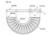
- FIG. 3 is a diagram showing a schematic configuration example of the fixed wing 50 according to the embodiment of the present invention, and the fixed wing 50 is provided with an outer rim 51 and an inner rim 52.
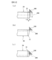
- FIG. 2 is a view for explaining the die-matching surface 200 when the fixed wing 50 according to the embodiment of the present invention is manufactured by casting. As shown in FIG.
- the mold matching surface 200 is located at the center of the uppermost (uppermost) surface and the lowermost (lowermost) surface of the fixed wing 50.
- the mold matching surface 200 is manufactured by casting.
- the fixed blade 50 is cast in this manner, as shown in FIG. 2 (a), two die-cut tapers ⁇ 1 and ⁇ 2 are formed, and the center of the fixed blade 50 in the thickness direction (that is, mold matching). Swelling due to the die-cutting taper ⁇ 1 and the die-cutting taper ⁇ 2 is formed at the position of the surface 200).
- a shaving press is applied to the swelled portion of the fixed blade 50 (the confluence of the die-cut taper) with a pressing tool 100 or the like.
- the position of the mold matching surface 200 does not have to be the above-described “just the center of the uppermost (uppermost surface) and lowermost (lowermost surface) of the fixed wing 50”, and the uppermost portion (uppermost surface) of the fixed wing 50. It suffices to be between the lowest part (lowermost surface).
- the mold matching surface 200 may be provided between the uppermost portion (uppermost surface) and the center of the fixed wing 50, or as shown in FIG. As described above, the mold matching surface 200 may be provided between the lowermost portion (lowermost surface) and the center of the fixed wing 50.
- the outer rim 51 has been described as an example, but the same configuration can be applied to the inner rim 52 as well. *
- the turbo molecular pump 1 can exhibit the following effects.
- the outer rim 51 and the inner rim 52 corresponding to the outer periphery of the fixed wing 50 are determined from portions (outer peripheral surfaces) where the fixed wing 50 contacts or faces other parts. Processing (finishing) such as a lathe or cutting to achieve the required accuracy is not necessary, and the shape of the outer peripheral surface of the fixed blade 50 can be determined by applying a shaving press using a blade 100 for pressing.
- the fixed wings 50 can be uniformly shave-pressed by using a press working blade 100.
- the thickness d of the outer rim 51 (inner rim 52) can be made thicker and balanced.
- turbo molecular pump 1 turbo molecular pump 2 casing 3 base 4 intake 4 flange 5 flange 6 exhaust 7 shaft 8 rotor 9 rotor blade 10 cylindrical rotating member 20 motor unit 30 radial magnetic bearing device 31 radial magnetic bearing device 40 axial magnetic bearing device 50 fixed wings 51 fixed wings (outer rims) 52 fixed wings (inner rims) 60 thread groove spacers 70 spacers 100 stamping blades 200 mold matching surfaces 500 fixed wings (conventional) 510 fixed wings (outer rims) 520 fixed wings (inner rim)
Landscapes
- Engineering & Computer Science (AREA)
- Mechanical Engineering (AREA)
- General Engineering & Computer Science (AREA)
- Non-Positive Displacement Air Blowers (AREA)
Abstract
【課題】真空ポンプにおいて、鋳物で製造され、仕上げ加工が不要な固定翼を備えた真空ポンプを提供する。【解決手段】本発明の実施形態の真空ポンプは、当該真空ポンプに配設される固定翼が、鋳造する際に使用する2枚の型の合わせ面(型合わせ面)の位置(場所)が、当該固定翼の上端と下端の間に位置するように構成される。つまり、真空ポンプにおいて吸気口側を上、排気口側を下とした場合、真空ポンプに配設される固定翼の上端(最上部)又は下端(最下部)ではないところに鋳造する際の型合わせ面が位置するようにして製造された固定翼を備えている。
Description
本発明は真空ポンプに関する。詳しくは、鋳物で製造され、仕上げ加工が不要な固定翼を備える真空ポンプに関する。
各種ある真空ポンプのうち、高真空の環境を実現するために多用されるものにターボ分子ポンプやねじ溝式ポンプがある。 ターボ分子ポンプやねじ溝式ポンプなどの真空ポンプを用いて排気処理を行うことで内部が真空に保たれる真空装置には、半導体製造装置用のチャンバ、電子顕微鏡の測定室、表面分析装置、微細加工装置などがある。 この高真空の環境を実現する真空ポンプは、吸気口及び排気口を備えた外装体を形成するケーシングを備えている。そして、このケーシングの内部には、当該真空ポンプに排気機能を発揮させる構造物が収納されている。この排気機能を発揮させる構造物は、大きく分けて、回転自在に軸支された回転部(ロータ部)とケーシングに対して固定された固定部(ステータ部)から構成されている。 ターボ分子ポンプの場合、回転部は、回転軸及びこの回転軸に固定されている回転体からなり、回転体には、放射状に設けられたロータ翼(動翼)が多段に配設されている。また、固定部には、ロータ翼に対して互い違いにステータ翼(静翼)が多段に配設されている。 また、回転軸を高速回転させるためのモータが設けられており、このモータの働きにより回転軸が高速回転すると、ロータ翼とステータ翼との相互作用により気体が吸気口から吸引され、排気口から排出されるようになっている。
特許文献1には、ターボ分子ポンプにおいて複数の分割固定翼をダイカスト鋳造によって製作する技術が記載されている。 特許文献2及び特許文献3は、固定翼を鋳物などで作る場合の加工影響を少なくするための技術が記載されている。固定翼スペーサと交互に積み重ねられる固定翼は、高さ位置を決められるものである。特に、固定翼をダイカスト鋳造で製造する場合は、高さ方向の精度は出るものの、側面にできる型(鋳物の型)の合わせ面の加工が必須になるため、切削加工を施すことが必要になる。
近年、材料費などの製造費削減や加工費用の削減を目的として、特許文献1に記載があるように、真空ポンプ(ターボ分子ポンプ)の固定翼をダイカスト鋳造で製造する場合がある。 図3、図4、及び図5は、従来のダイカスト鋳造で製造された固定翼500を説明するための図である。 図3に示したように、固定翼500を鋳物で製造した場合、固定翼500の外周に相当する外リム510及び内リム520の上下面α及び側面β(点線A内)といった、他の部品と接する又は対向する部分(面)を有する部品には、定められた精度を実現するために、旋盤や切削などの加工(仕上げ加工)が必要だった。 詳しくは、図4に示したように、従来のダイカスト鋳造で製造する場合、ダイカスト鋳造に用いられる型から製品を抜き取るために、傾斜角度がおよそ1°~5°程度の型抜きテーパγを設けており、この角度をなくし部品の側面βを平らにするために旋盤や切削などの加工でこの型抜きテーパγの角度を削る必要があった。 型抜きテーパγはプレス加工の刃物100により加工される。 ここで、図4に示したように、ダイカスト鋳造の型合わせ面200が固定翼500の最上部(最上面)に設けられた場合、型抜きテーパγが設けられた外リム510がプレス加工の刃物100で加工されると、B部(図4)に示したように、加工開始地点にヒビが発生する場合があった。 一方、図5に示したように、ダイカスト鋳造の型合わせ面200が固定翼500の最下部(最下面)に設けられた場合、型抜きテーパγが設けられた外リム510がプレス加工の刃物100で加工されると(図面上部)、C部(図面下部)に示したように、加工終了地点にダレが発生する場合があった。
そこで、本発明は、真空ポンプにおいて、鋳物で製造され、仕上げ加工が不要な固定翼を備える真空ポンプを提供することを目的とする。
上記目的を達成するために、請求項1記載の本願発明では、吸気口と排気口が形成された外装体と、前記外装体に内包され、回転自在に支持された回転軸と、前記回転軸に固定される回転体と、前記回転体の外周面から放射状に配設された回転翼と、前記回転翼の間に配置された固定翼と、前記回転翼と前記固定翼との相互作用により前記吸気口から吸気した気体を前記排気口へ移送する気体移送機構と、を備え、前記固定翼は、鋳造される際の型合わせ面が、当該固定翼における前記吸気口側の面と前記排気口側の面の間に位置するように製造されることを特徴とする真空ポンプを提供する。 請求項2記載の本願発明では、前記固定翼は、シェービングプレス加工によって外周面の形状が定められることを特徴とする請求項1記載の真空ポンプを提供する。
本発明によれば、鋳物で製造され、仕上げ加工が不要な固定翼を備える真空ポンプを提供することができる。
(i)実施形態の概要 本発明の実施形態の真空ポンプは、当該真空ポンプに配設される固定翼が、鋳造する際に使用する2枚の型の合わせ面(以後、型合わせ面)の位置(場所)が、当該固定翼の上端と下端の間に位置するように構成されている。つまり、真空ポンプにおいて吸気口側を上、排気口側を下とした場合、真空ポンプに配設される固定翼の上端(最上部・最上面)又は下端(最下部・最下面)ではないところに鋳造する際の型合わせ面が位置するように製造された固定翼を備えている。
(ii)実施形態の詳細 以下、本発明の好適な実施の形態について、図1、図2、及び図3を参照して詳細に説明する。 なお、本第1実施形態では、真空ポンプの一例として、ターボ分子ポンプ部(第2気体移送機構)とねじ溝式ポンプ部(第1気体移送機構)を備えた、いわゆる複合型のターボ分子ポンプを用いて説明する。
図1は、本発明の実施形態に係るターボ分子ポンプ1の概略構成例を示した図である。なお、図1は、ターボ分子ポンプ1の軸線方向の断面図を示している。 ターボ分子ポンプ1の外装体を形成するケーシング2は、略円筒状の形状をしており、ケーシング2の下部(排気口6側)に設けられたベース3と共にターボ分子ポンプ1の筐体を構成している。そして、この筐体の内部には、ターボ分子ポンプ1に排気機能を発揮させる構造物である気体移送機構が収納されている。 この気体移送機構は、大きく分けて、回転自在に軸支された回転部と筐体に対して固定された固定部から構成されている。
ケーシング2の端部には、当該ターボ分子ポンプ1へ気体を導入するための吸気口4が形成されている。また、ケーシング2の吸気口4側の端面には、外周側へ張り出したフランジ部5が形成されている。 また、ベース3には、当該ターボ分子ポンプ1から気体を排気するための排気口6が形成されている。
回転部は、回転軸であるシャフト7、このシャフト7に配設されたロータ8、ロータ8に設けられた複数枚の回転翼9、排気口6側(ねじ溝式ポンプ部)に設けられた筒型回転部材10などから構成されている。なお、シャフト7及びロータ8によってロータ部が構成されている。 各回転翼9は、シャフト7の軸線に垂直な平面から所定の角度だけ傾斜してシャフト7から放射状に伸びたブレードからなる。 また、筒型回転部材10は、ロータ8の回転軸線と同心の円筒形状をした円筒部材からなる。
シャフト7の軸線方向中程には、シャフト7を高速回転させるためのモータ部20が設けられている。 更に、シャフト7のモータ部20に対して吸気口4側、および排気口6側には、シャフト7をラジアル方向(径方向)に非接触で支持(軸支)するための径方向磁気軸受装置30、31、シャフト7の下端には、シャフト7を軸線方向(アキシャル方向)に非接触で支持(軸支)するための軸方向磁気軸受装置40が設けられている。
筐体の内周側には、固定部が形成されている。この固定部は、吸気口4側(ターボ分子ポンプ部)に設けられた複数枚の固定翼50と、ケーシング2の内周面に設けられたねじ溝スペーサ60などから構成されている。 各固定翼50は、シャフト7の軸線に垂直な平面から所定の角度だけ傾斜して筐体の内周面からシャフト7に向かって伸びたブレードから構成されている。 各段の固定翼50は、円筒形状をしたスペーサ70により互いに隔てられて固定されている。 ターボ分子ポンプ部では、固定翼50と、回転翼9とが互い違いに配置され、軸線方向に複数段形成されている。
ねじ溝スペーサ60には、各々の筒型回転部材10との対向面にらせん溝が形成されている。そして、ねじ溝スペーサ60は所定のクリアランスを隔てて筒型回転部材10の外周面に対面しており、筒型回転部材10が高速回転すると、ターボ分子ポンプ1で圧縮されたガスが筒型回転部材10の回転に伴ってねじ溝(らせん溝)にガイドされながら排気口6側へ送出されるようになっている。即ち、ねじ溝は、ガスを輸送する流路となっている。ねじ溝スペーサ60と筒型回転部材10が所定のクリアランスを隔てて対向することにより、ねじ溝でガスを移送する気体移送機構(第1気体移送機構)を構成している。 なお、ガスが吸気口4側へ逆流する力を低減させるために、このクリアランスは小さければ小さいほど良い。 ねじ溝スペーサ60に形成されたらせん溝の方向は、らせん溝内をロータ8の回転方向にガスが輸送された場合、排気口6に向かう方向である。 また、らせん溝の深さは、排気口6に近づくにつれて浅くなるようになっており、らせん溝を輸送されるガスは排気口6に近づくにつれて圧縮されるようになっている。このように、吸気口4から吸引されたガスは、ターボ分子ポンプ部(第2気体移送機構)で圧縮された後、ねじ溝式ポンプ部(第1気体移送機構)で更に圧縮されて排気口6から排出される。 このように構成されたターボ分子ポンプ1により、ターボ分子ポンプ1に配設される真空室(図示しない)内の真空排気処理を行うようになっている。
上述した本発明の実施形態に係るターボ分子ポンプ1は、ターボ分子ポンプ部において、鋳造で製造された固定翼50を有する。なお、本実施形態では鋳造方法の一例として、固定翼50はダイカスト鋳造で製造する場合について説明するが、ダイカスト鋳造に限定されることはない。 図3は、本発明の実施形態に係る固定翼50の概略構成例を示した図であり、固定翼50には外リム51及び内リム52が設けられている。 図2は、本発明の実施形態に係る固定翼50を鋳造で製造する際の型合わせ面200を説明するための図である。 図2(a)に示したように、本発明の実施形態に係る固定翼50は、型合わせ面200が固定翼50の最上部(最上面)と最下部(最下面)のちょうど中央に位置するようにして鋳造で製造される。 固定翼50をこのように鋳造すると、図2(a)に示したように、2箇所の型抜きテーパγ1及び型抜きテーパγ2が形成され、固定翼50の厚み方向の中央(即ち、型合わせ面200の位置)に当該型抜きテーパγ1及び型抜きテーパγ2による盛り上がりが形成される。 そして、固定翼50における当該盛り上がった部分(型抜きテーパの合流点)に対して、プレス加工の刃物100などでシェービングプレスを施す。この作業によ
り固定翼50の最上部(最上面)と最下部(最下面)に加工によるバリやダレが発生しないようにすることができる。 仮に、加工時にバリやダレが発生した場合であっても、その影響を小さくすることができる。つまり、型合わせ面が最上部と最下部の中央に位置しているので、仮にバリやダレが発生したとしても、当該バリやダレが他の部品と接触する可能性は小さく、当該バリやダレが他の部品に与える影響が小さくなるためである。
り固定翼50の最上部(最上面)と最下部(最下面)に加工によるバリやダレが発生しないようにすることができる。 仮に、加工時にバリやダレが発生した場合であっても、その影響を小さくすることができる。つまり、型合わせ面が最上部と最下部の中央に位置しているので、仮にバリやダレが発生したとしても、当該バリやダレが他の部品と接触する可能性は小さく、当該バリやダレが他の部品に与える影響が小さくなるためである。
なお、型合わせ面200の位置は上述した「固定翼50の最上部(最上面)と最下部(最下面)のちょうど中央」である必要はなく、固定翼50の最上部(最上面)と最下部(最下面)の間であればよい。 例えば、図2(b)に示したように、型合わせ面200が固定翼50の最上部(最上面)と中央の間に設けられても良いし、或いは、図2(c)に示したように、型合わせ面200が固定翼50の最下部(最下面)と中央の間に設けられても良い。
なお、本実施形態では、一例として外リム51を用いて説明したが、同様の構成を内リム52にも適用することができる。
この構成により、本発明の実施形態に係るターボ分子ポンプ1は、以下の効果を奏することができる。(1)固定翼50の外周に相当する外リム51及び内リム52の上下面α及び側面β(図3)といった、固定翼50が他の部品と接する又は対向する部分(外周面)に求められる精度を実現するための旋盤や切削などの加工(仕上げ加工)が不必要になり、プレス加工の刃物100を用いるシェービングプレスを施すことにより固定翼50の外周面の形状を定めることが出来る。(2)固定翼50を、プレス加工の刃物100を用いて、均等にシェービングプレスすることができる。(3)プレス加工の刃物100を用いるシェービングプレスで型抜きテーパの傾斜部分を切り落とす際に、ヒビ(図4:B部のような)が発生するのを低減することが出来る。(4)プレス加工の刃物100を用いるシェービングプレスで型抜きテーパの傾斜部分を切り落とす際に、固定翼50の端面(最上面や最下面)にバリや加工ダレが発生するのを低減し、仮にバリや加工ダレが発生した場合であっても影響を小さくすることが出来る。(5)型抜きテーパによる盛り上がり位置を、固定翼50の厚み方向の中央(図2(a)の型合わせ面200の位置)にすることで、プレス加工の刃物100を用いるシェービングプレスで型抜きテーパの傾斜部分を切り落とした後に、外リム51(内リム52)の厚みdに差ができにくくすることができ、均一な厚さの外リム51(内リム52)を形成することができる。言い換えると、外リム51(内リム52)の厚みdを、より厚く、バランス良く加工することができる。
1 ターボ分子ポンプ 2 ケーシング 3 ベース 4 吸気口 5 フランジ部 6 排気口 7 シャフト 8 ロータ 9 回転翼 10 筒型回転部材 20 モータ部 30 径方向磁気軸受装置 31 径方向磁気軸受装置 40 軸方向磁気軸受装置 50 固定翼 51 固定翼(外リム) 52 固定翼(内リム) 60 ねじ溝スペーサ 70 スペーサ 100 プレス加工の刃物 200 型合わせ面 500 固定翼(従来) 510 固定翼(外リム) 520 固定翼(内リム)
Claims (2)
- 吸気口と排気口が形成された外装体と、 前記外装体に内包され、回転自在に支持された回転軸と、 前記回転軸に固定される回転体と、 前記回転体の外周面から放射状に配設された回転翼と、 前記回転翼の間に配置された固定翼と、 前記回転翼と前記固定翼との相互作用により前記吸気口から吸気した気体を前記排気口へ移送する気体移送機構と、を備え、 前記固定翼は、鋳造される際の型合わせ面が、当該固定翼における前記吸気口側の面と前記排気口側の面の間に位置するように製造されることを特徴とする真空ポンプ。
- 前記固定翼は、シェービングプレス加工によって外周面の形状が定められることを特徴とする請求項1記載の真空ポンプ。
Priority Applications (1)
| Application Number | Priority Date | Filing Date | Title |
|---|---|---|---|
| CN201380052579.XA CN104685216B (zh) | 2012-11-08 | 2013-10-09 | 真空泵 |
Applications Claiming Priority (2)
| Application Number | Priority Date | Filing Date | Title |
|---|---|---|---|
| JP2012246273A JP6125801B2 (ja) | 2012-11-08 | 2012-11-08 | 真空ポンプ |
| JP2012-246273 | 2012-11-08 |
Publications (1)
| Publication Number | Publication Date |
|---|---|
| WO2014073315A1 true WO2014073315A1 (ja) | 2014-05-15 |
Family
ID=50684432
Family Applications (1)
| Application Number | Title | Priority Date | Filing Date |
|---|---|---|---|
| PCT/JP2013/077508 Ceased WO2014073315A1 (ja) | 2012-11-08 | 2013-10-09 | 真空ポンプ |
Country Status (3)
| Country | Link |
|---|---|
| JP (1) | JP6125801B2 (ja) |
| CN (1) | CN104685216B (ja) |
| WO (1) | WO2014073315A1 (ja) |
Citations (2)
| Publication number | Priority date | Publication date | Assignee | Title |
|---|---|---|---|---|
| JPH10169753A (ja) * | 1996-12-11 | 1998-06-26 | Nissan Motor Co Ltd | トルクコンバータ |
| JP2007309245A (ja) * | 2006-05-19 | 2007-11-29 | Boc Edwards Kk | 真空ポンプ |
Family Cites Families (6)
| Publication number | Priority date | Publication date | Assignee | Title |
|---|---|---|---|---|
| JP3849392B2 (ja) * | 2000-02-29 | 2006-11-22 | 三菱ふそうトラック・バス株式会社 | キャブマウント装置 |
| JP2003269364A (ja) * | 2002-03-12 | 2003-09-25 | Boc Edwards Technologies Ltd | 真空ポンプ |
| CN1274963C (zh) * | 2002-06-25 | 2006-09-13 | 台达电子工业股份有限公司 | 散热风扇及其制作方法 |
| JP2008196331A (ja) * | 2007-02-09 | 2008-08-28 | Shimadzu Corp | 回転真空ポンプ |
| CN101713417B (zh) * | 2008-10-08 | 2012-06-13 | 日本电产伺服有限公司 | 叶轮、使用叶轮的风扇装置和制造叶轮的方法 |
| JP5397138B2 (ja) * | 2009-10-02 | 2014-01-22 | 株式会社島津製作所 | ターボ分子ポンプ |
-
2012
- 2012-11-08 JP JP2012246273A patent/JP6125801B2/ja not_active Expired - Fee Related
-
2013
- 2013-10-09 WO PCT/JP2013/077508 patent/WO2014073315A1/ja not_active Ceased
- 2013-10-09 CN CN201380052579.XA patent/CN104685216B/zh active Active
Patent Citations (2)
| Publication number | Priority date | Publication date | Assignee | Title |
|---|---|---|---|---|
| JPH10169753A (ja) * | 1996-12-11 | 1998-06-26 | Nissan Motor Co Ltd | トルクコンバータ |
| JP2007309245A (ja) * | 2006-05-19 | 2007-11-29 | Boc Edwards Kk | 真空ポンプ |
Also Published As
| Publication number | Publication date |
|---|---|
| CN104685216B (zh) | 2017-03-08 |
| JP2014095313A (ja) | 2014-05-22 |
| JP6125801B2 (ja) | 2017-05-10 |
| CN104685216A (zh) | 2015-06-03 |
Similar Documents
| Publication | Publication Date | Title |
|---|---|---|
| KR102106658B1 (ko) | 로터, 및, 이 로터를 구비한 진공 펌프 | |
| WO2011132509A1 (ja) | 過給機用のコンプレッサハウジング及びその製造方法 | |
| CN109844321B (zh) | 真空泵、以及真空泵中具备的螺旋状板、间隔件及旋转圆筒体 | |
| US9670931B2 (en) | Rotary vacuum pump | |
| WO2007135883A1 (ja) | 真空ポンプ | |
| JP5670095B2 (ja) | 真空ポンプ | |
| WO2006027961A1 (ja) | ターボ分子ポンプ固定翼 | |
| CN104047871B (zh) | 真空泵 | |
| JP6133213B2 (ja) | 固定部材及び真空ポンプ | |
| US9879685B2 (en) | Rotary machine, blade wheel used in rotary machine, and blade wheel manufacturing method | |
| WO2006137333A1 (ja) | ターボ分子ポンプ、およびターボ分子ポンプの組み立て方法 | |
| JP6148717B2 (ja) | ローターディスク | |
| JP6125801B2 (ja) | 真空ポンプ | |
| CN103939368B (zh) | 真空泵 | |
| JP2003269365A (ja) | 真空ポンプ | |
| JP6834612B2 (ja) | 真空ポンプの製造方法 | |
| WO2018043072A1 (ja) | 真空ポンプ、および真空ポンプに備わる回転円筒体 | |
| CN104033395B (zh) | 真空泵 | |
| CN118991077A (zh) | 转子叶片的制造方法、真空泵的转子叶片、真空泵 | |
| JP5110738B2 (ja) | 過給機用のコンプレッサハウジング | |
| JP2018168732A (ja) | 真空ポンプ | |
| JP2015135074A (ja) | ターボ分子ポンプ | |
| JP2004360697A (ja) | 真空ポンプ用固定翼の製造方法およびそれにより得られる固定翼 | |
| JP6735119B2 (ja) | 真空ポンプ及びそれに使用される静翼部 | |
| JPS6361798A (ja) | 多段一体羽根車 |
Legal Events
| Date | Code | Title | Description |
|---|---|---|---|
| 121 | Ep: the epo has been informed by wipo that ep was designated in this application |
Ref document number: 13853553 Country of ref document: EP Kind code of ref document: A1 |
|
| NENP | Non-entry into the national phase |
Ref country code: DE |
|
| 122 | Ep: pct application non-entry in european phase |
Ref document number: 13853553 Country of ref document: EP Kind code of ref document: A1 |