WO2014073072A1 - ミラー装置 - Google Patents
ミラー装置 Download PDFInfo
- Publication number
- WO2014073072A1 WO2014073072A1 PCT/JP2012/078971 JP2012078971W WO2014073072A1 WO 2014073072 A1 WO2014073072 A1 WO 2014073072A1 JP 2012078971 W JP2012078971 W JP 2012078971W WO 2014073072 A1 WO2014073072 A1 WO 2014073072A1
- Authority
- WO
- WIPO (PCT)
- Prior art keywords
- mirror surface
- organic
- metal
- light
- metal mirror
- Prior art date
Links
- 229910052751 metal Inorganic materials 0.000 claims abstract description 115
- 239000002184 metal Substances 0.000 claims abstract description 115
- 239000010410 layer Substances 0.000 claims abstract description 76
- 239000000758 substrate Substances 0.000 claims abstract description 44
- 239000012044 organic layer Substances 0.000 claims abstract description 29
- 238000009826 distribution Methods 0.000 claims description 3
- 239000011159 matrix material Substances 0.000 claims description 3
- 238000000638 solvent extraction Methods 0.000 claims 1
- 150000001875 compounds Chemical class 0.000 description 30
- 239000000463 material Substances 0.000 description 30
- 239000010408 film Substances 0.000 description 24
- 238000002347 injection Methods 0.000 description 21
- 239000007924 injection Substances 0.000 description 21
- 230000004048 modification Effects 0.000 description 19
- 238000012986 modification Methods 0.000 description 19
- -1 silazane derivatives Chemical class 0.000 description 14
- 230000032258 transport Effects 0.000 description 13
- 238000000034 method Methods 0.000 description 12
- 230000005525 hole transport Effects 0.000 description 9
- 238000000605 extraction Methods 0.000 description 8
- 238000007789 sealing Methods 0.000 description 8
- 239000010409 thin film Substances 0.000 description 7
- KDLHZDBZIXYQEI-UHFFFAOYSA-N Palladium Chemical compound [Pd] KDLHZDBZIXYQEI-UHFFFAOYSA-N 0.000 description 6
- JUJWROOIHBZHMG-UHFFFAOYSA-N Pyridine Chemical compound C1=CC=NC=C1 JUJWROOIHBZHMG-UHFFFAOYSA-N 0.000 description 6
- 239000011521 glass Substances 0.000 description 6
- 239000003446 ligand Substances 0.000 description 6
- 150000004982 aromatic amines Chemical class 0.000 description 5
- 230000004888 barrier function Effects 0.000 description 5
- 238000000576 coating method Methods 0.000 description 5
- 238000005286 illumination Methods 0.000 description 5
- 238000002834 transmittance Methods 0.000 description 5
- VYPSYNLAJGMNEJ-UHFFFAOYSA-N Silicium dioxide Chemical compound O=[Si]=O VYPSYNLAJGMNEJ-UHFFFAOYSA-N 0.000 description 4
- BQCADISMDOOEFD-UHFFFAOYSA-N Silver Chemical compound [Ag] BQCADISMDOOEFD-UHFFFAOYSA-N 0.000 description 4
- 229910045601 alloy Inorganic materials 0.000 description 4
- 239000000956 alloy Substances 0.000 description 4
- 125000003118 aryl group Chemical group 0.000 description 4
- 230000000694 effects Effects 0.000 description 4
- 239000007850 fluorescent dye Substances 0.000 description 4
- 239000007789 gas Substances 0.000 description 4
- 125000005842 heteroatom Chemical group 0.000 description 4
- 229910052763 palladium Inorganic materials 0.000 description 4
- 230000036961 partial effect Effects 0.000 description 4
- 230000000737 periodic effect Effects 0.000 description 4
- BASFCYQUMIYNBI-UHFFFAOYSA-N platinum Chemical compound [Pt] BASFCYQUMIYNBI-UHFFFAOYSA-N 0.000 description 4
- 229920000642 polymer Polymers 0.000 description 4
- 229920005989 resin Polymers 0.000 description 4
- 239000011347 resin Substances 0.000 description 4
- 229910052709 silver Inorganic materials 0.000 description 4
- 239000004332 silver Substances 0.000 description 4
- VQGHOUODWALEFC-UHFFFAOYSA-N 2-phenylpyridine Chemical compound C1=CC=CC=C1C1=CC=CC=N1 VQGHOUODWALEFC-UHFFFAOYSA-N 0.000 description 3
- DHDHJYNTEFLIHY-UHFFFAOYSA-N 4,7-diphenyl-1,10-phenanthroline Chemical compound C1=CC=CC=C1C1=CC=NC2=C1C=CC1=C(C=3C=CC=CC=3)C=CN=C21 DHDHJYNTEFLIHY-UHFFFAOYSA-N 0.000 description 3
- OYPRJOBELJOOCE-UHFFFAOYSA-N Calcium Chemical compound [Ca] OYPRJOBELJOOCE-UHFFFAOYSA-N 0.000 description 3
- 229910052791 calcium Inorganic materials 0.000 description 3
- 239000011575 calcium Substances 0.000 description 3
- 239000003086 colorant Substances 0.000 description 3
- 239000000470 constituent Substances 0.000 description 3
- 229920000412 polyarylene Polymers 0.000 description 3
- 229920000123 polythiophene Polymers 0.000 description 3
- UMJSCPRVCHMLSP-UHFFFAOYSA-N pyridine Natural products COC1=CC=CN=C1 UMJSCPRVCHMLSP-UHFFFAOYSA-N 0.000 description 3
- 239000002356 single layer Substances 0.000 description 3
- 229920003002 synthetic resin Polymers 0.000 description 3
- 239000000057 synthetic resin Substances 0.000 description 3
- TVIVIEFSHFOWTE-UHFFFAOYSA-K tri(quinolin-8-yloxy)alumane Chemical compound [Al+3].C1=CN=C2C([O-])=CC=CC2=C1.C1=CN=C2C([O-])=CC=CC2=C1.C1=CN=C2C([O-])=CC=CC2=C1 TVIVIEFSHFOWTE-UHFFFAOYSA-K 0.000 description 3
- 238000001771 vacuum deposition Methods 0.000 description 3
- STTGYIUESPWXOW-UHFFFAOYSA-N 2,9-dimethyl-4,7-diphenyl-1,10-phenanthroline Chemical compound C=12C=CC3=C(C=4C=CC=CC=4)C=C(C)N=C3C2=NC(C)=CC=1C1=CC=CC=C1 STTGYIUESPWXOW-UHFFFAOYSA-N 0.000 description 2
- VFUDMQLBKNMONU-UHFFFAOYSA-N 9-[4-(4-carbazol-9-ylphenyl)phenyl]carbazole Chemical group C12=CC=CC=C2C2=CC=CC=C2N1C1=CC=C(C=2C=CC(=CC=2)N2C3=CC=CC=C3C3=CC=CC=C32)C=C1 VFUDMQLBKNMONU-UHFFFAOYSA-N 0.000 description 2
- 229910001316 Ag alloy Inorganic materials 0.000 description 2
- 229910001148 Al-Li alloy Inorganic materials 0.000 description 2
- 101100077149 Human herpesvirus 8 type P (isolate GK18) K5 gene Proteins 0.000 description 2
- DGAQECJNVWCQMB-PUAWFVPOSA-M Ilexoside XXIX Chemical compound C[C@@H]1CC[C@@]2(CC[C@@]3(C(=CC[C@H]4[C@]3(CC[C@@H]5[C@@]4(CC[C@@H](C5(C)C)OS(=O)(=O)[O-])C)C)[C@@H]2[C@]1(C)O)C)C(=O)O[C@H]6[C@@H]([C@H]([C@@H]([C@H](O6)CO)O)O)O.[Na+] DGAQECJNVWCQMB-PUAWFVPOSA-M 0.000 description 2
- 229910000846 In alloy Inorganic materials 0.000 description 2
- FYYHWMGAXLPEAU-UHFFFAOYSA-N Magnesium Chemical compound [Mg] FYYHWMGAXLPEAU-UHFFFAOYSA-N 0.000 description 2
- UFWIBTONFRDIAS-UHFFFAOYSA-N Naphthalene Chemical compound C1=CC=CC2=CC=CC=C21 UFWIBTONFRDIAS-UHFFFAOYSA-N 0.000 description 2
- 229920001609 Poly(3,4-ethylenedioxythiophene) Polymers 0.000 description 2
- NRCMAYZCPIVABH-UHFFFAOYSA-N Quinacridone Chemical class N1C2=CC=CC=C2C(=O)C2=C1C=C1C(=O)C3=CC=CC=C3NC1=C2 NRCMAYZCPIVABH-UHFFFAOYSA-N 0.000 description 2
- ATJFFYVFTNAWJD-UHFFFAOYSA-N Tin Chemical compound [Sn] ATJFFYVFTNAWJD-UHFFFAOYSA-N 0.000 description 2
- JFBZPFYRPYOZCQ-UHFFFAOYSA-N [Li].[Al] Chemical compound [Li].[Al] JFBZPFYRPYOZCQ-UHFFFAOYSA-N 0.000 description 2
- JHYLKGDXMUDNEO-UHFFFAOYSA-N [Mg].[In] Chemical compound [Mg].[In] JHYLKGDXMUDNEO-UHFFFAOYSA-N 0.000 description 2
- 229910052783 alkali metal Inorganic materials 0.000 description 2
- 150000001340 alkali metals Chemical class 0.000 description 2
- AZDRQVAHHNSJOQ-UHFFFAOYSA-N alumane Chemical class [AlH3] AZDRQVAHHNSJOQ-UHFFFAOYSA-N 0.000 description 2
- 229910052782 aluminium Inorganic materials 0.000 description 2
- XAGFODPZIPBFFR-UHFFFAOYSA-N aluminium Chemical compound [Al] XAGFODPZIPBFFR-UHFFFAOYSA-N 0.000 description 2
- MWPLVEDNUUSJAV-UHFFFAOYSA-N anthracene Chemical compound C1=CC=CC2=CC3=CC=CC=C3C=C21 MWPLVEDNUUSJAV-UHFFFAOYSA-N 0.000 description 2
- 229910052792 caesium Inorganic materials 0.000 description 2
- TVFDJXOCXUVLDH-UHFFFAOYSA-N caesium atom Chemical compound [Cs] TVFDJXOCXUVLDH-UHFFFAOYSA-N 0.000 description 2
- WDECIBYCCFPHNR-UHFFFAOYSA-N chrysene Chemical compound C1=CC=CC2=CC=C3C4=CC=CC=C4C=CC3=C21 WDECIBYCCFPHNR-UHFFFAOYSA-N 0.000 description 2
- 239000003989 dielectric material Substances 0.000 description 2
- 238000005401 electroluminescence Methods 0.000 description 2
- 125000005678 ethenylene group Chemical class [H]C([*:1])=C([H])[*:2] 0.000 description 2
- HVQAJTFOCKOKIN-UHFFFAOYSA-N flavonol Chemical compound O1C2=CC=CC=C2C(=O)C(O)=C1C1=CC=CC=C1 HVQAJTFOCKOKIN-UHFFFAOYSA-N 0.000 description 2
- 125000003983 fluorenyl group Chemical group C1(=CC=CC=2C3=CC=CC=C3CC12)* 0.000 description 2
- 229910052738 indium Inorganic materials 0.000 description 2
- APFVFJFRJDLVQX-UHFFFAOYSA-N indium atom Chemical compound [In] APFVFJFRJDLVQX-UHFFFAOYSA-N 0.000 description 2
- 238000010030 laminating Methods 0.000 description 2
- 239000001989 lithium alloy Substances 0.000 description 2
- 229910052749 magnesium Inorganic materials 0.000 description 2
- 239000011777 magnesium Substances 0.000 description 2
- SJCKRGFTWFGHGZ-UHFFFAOYSA-N magnesium silver Chemical compound [Mg].[Ag] SJCKRGFTWFGHGZ-UHFFFAOYSA-N 0.000 description 2
- 108091084679 miR-3 stem-loop Proteins 0.000 description 2
- 108091033354 miR-3-1 stem-loop Proteins 0.000 description 2
- 108091058771 miR-3-2 stem-loop Proteins 0.000 description 2
- 229910052757 nitrogen Inorganic materials 0.000 description 2
- IEQIEDJGQAUEQZ-UHFFFAOYSA-N phthalocyanine Chemical class N1C(N=C2C3=CC=CC=C3C(N=C3C4=CC=CC=C4C(=N4)N3)=N2)=C(C=CC=C2)C2=C1N=C1C2=CC=CC=C2C4=N1 IEQIEDJGQAUEQZ-UHFFFAOYSA-N 0.000 description 2
- 229910052697 platinum Inorganic materials 0.000 description 2
- 229920000553 poly(phenylenevinylene) Polymers 0.000 description 2
- 150000004033 porphyrin derivatives Chemical class 0.000 description 2
- 150000004032 porphyrins Chemical class 0.000 description 2
- BBEAQIROQSPTKN-UHFFFAOYSA-N pyrene Chemical compound C1=CC=C2C=CC3=CC=CC4=CC=C1C2=C43 BBEAQIROQSPTKN-UHFFFAOYSA-N 0.000 description 2
- 230000002829 reductive effect Effects 0.000 description 2
- 229910052814 silicon oxide Inorganic materials 0.000 description 2
- 150000003967 siloles Chemical class 0.000 description 2
- 229910052708 sodium Inorganic materials 0.000 description 2
- 239000011734 sodium Substances 0.000 description 2
- 238000004544 sputter deposition Methods 0.000 description 2
- 150000003512 tertiary amines Chemical class 0.000 description 2
- 229910052718 tin Inorganic materials 0.000 description 2
- PFNQVRZLDWYSCW-UHFFFAOYSA-N (fluoren-9-ylideneamino) n-naphthalen-1-ylcarbamate Chemical compound C12=CC=CC=C2C2=CC=CC=C2C1=NOC(=O)NC1=CC=CC2=CC=CC=C12 PFNQVRZLDWYSCW-UHFFFAOYSA-N 0.000 description 1
- NKEWBOPVULFSFJ-UHFFFAOYSA-N 1,3-dihydroperimidin-2-one Chemical class C1=CC(NC(O)=N2)=C3C2=CC=CC3=C1 NKEWBOPVULFSFJ-UHFFFAOYSA-N 0.000 description 1
- IJAAWBHHXIWAHM-UHFFFAOYSA-N 1,4-bis(2-phenylethenyl)benzene Chemical compound C=1C=CC=CC=1C=CC(C=C1)=CC=C1C=CC1=CC=CC=C1 IJAAWBHHXIWAHM-UHFFFAOYSA-N 0.000 description 1
- ZMLPKJYZRQZLDA-UHFFFAOYSA-N 1-(2-phenylethenyl)-4-[4-(2-phenylethenyl)phenyl]benzene Chemical group C=1C=CC=CC=1C=CC(C=C1)=CC=C1C(C=C1)=CC=C1C=CC1=CC=CC=C1 ZMLPKJYZRQZLDA-UHFFFAOYSA-N 0.000 description 1
- ZVFJWYZMQAEBMO-UHFFFAOYSA-N 1h-benzo[h]quinolin-10-one Chemical compound C1=CNC2=C3C(=O)C=CC=C3C=CC2=C1 ZVFJWYZMQAEBMO-UHFFFAOYSA-N 0.000 description 1
- GKWLILHTTGWKLQ-UHFFFAOYSA-N 2,3-dihydrothieno[3,4-b][1,4]dioxine Chemical compound O1CCOC2=CSC=C21 GKWLILHTTGWKLQ-UHFFFAOYSA-N 0.000 description 1
- MUNFOTHAFHGRIM-UHFFFAOYSA-N 2,5-dinaphthalen-1-yl-1,3,4-oxadiazole Chemical compound C1=CC=C2C(C3=NN=C(O3)C=3C4=CC=CC=C4C=CC=3)=CC=CC2=C1 MUNFOTHAFHGRIM-UHFFFAOYSA-N 0.000 description 1
- YLYPIBBGWLKELC-RMKNXTFCSA-N 2-[2-[(e)-2-[4-(dimethylamino)phenyl]ethenyl]-6-methylpyran-4-ylidene]propanedinitrile Chemical class C1=CC(N(C)C)=CC=C1\C=C\C1=CC(=C(C#N)C#N)C=C(C)O1 YLYPIBBGWLKELC-RMKNXTFCSA-N 0.000 description 1
- PWJWTARLFLETPP-UHFFFAOYSA-N 2-n,3-n,4-n-trinaphthalen-1-yl-1-n,1-n,2-n,3-n,4-n-pentakis-phenylbenzene-1,2,3,4-tetramine Chemical compound C1=CC=CC=C1N(C=1C(=C(N(C=2C=CC=CC=2)C=2C3=CC=CC=C3C=CC=2)C(N(C=2C=CC=CC=2)C=2C3=CC=CC=C3C=CC=2)=CC=1)N(C=1C=CC=CC=1)C=1C2=CC=CC=C2C=CC=1)C1=CC=CC=C1 PWJWTARLFLETPP-UHFFFAOYSA-N 0.000 description 1
- NSMJMUQZRGZMQC-UHFFFAOYSA-N 2-naphthalen-1-yl-1H-imidazo[4,5-f][1,10]phenanthroline Chemical compound C12=CC=CN=C2C2=NC=CC=C2C2=C1NC(C=1C3=CC=CC=C3C=CC=1)=N2 NSMJMUQZRGZMQC-UHFFFAOYSA-N 0.000 description 1
- FLEKYFPINOSNRF-UHFFFAOYSA-N 2-phenylpyridine;rhenium Chemical compound [Re].C1=CC=CC=C1C1=CC=CC=N1.C1=CC=CC=C1C1=CC=CC=N1.C1=CC=CC=C1C1=CC=CC=N1 FLEKYFPINOSNRF-UHFFFAOYSA-N 0.000 description 1
- GOLORTLGFDVFDW-UHFFFAOYSA-N 3-(1h-benzimidazol-2-yl)-7-(diethylamino)chromen-2-one Chemical compound C1=CC=C2NC(C3=CC4=CC=C(C=C4OC3=O)N(CC)CC)=NC2=C1 GOLORTLGFDVFDW-UHFFFAOYSA-N 0.000 description 1
- IYBLVRRCNVHZQJ-UHFFFAOYSA-N 5-Hydroxyflavone Chemical class C=1C(=O)C=2C(O)=CC=CC=2OC=1C1=CC=CC=C1 IYBLVRRCNVHZQJ-UHFFFAOYSA-N 0.000 description 1
- OEDUIFSDODUDRK-UHFFFAOYSA-N 5-phenyl-1h-pyrazole Chemical compound N1N=CC=C1C1=CC=CC=C1 OEDUIFSDODUDRK-UHFFFAOYSA-N 0.000 description 1
- 239000005725 8-Hydroxyquinoline Substances 0.000 description 1
- 229910018072 Al 2 O 3 Inorganic materials 0.000 description 1
- OKTJSMMVPCPJKN-UHFFFAOYSA-N Carbon Chemical compound [C] OKTJSMMVPCPJKN-UHFFFAOYSA-N 0.000 description 1
- 241000284156 Clerodendrum quadriloculare Species 0.000 description 1
- 102100038546 Fibronectin type III and SPRY domain-containing protein 1 Human genes 0.000 description 1
- 108010043121 Green Fluorescent Proteins Proteins 0.000 description 1
- 101001030521 Homo sapiens Fibronectin type III and SPRY domain-containing protein 1 Proteins 0.000 description 1
- 229910018068 Li 2 O Inorganic materials 0.000 description 1
- WHXSMMKQMYFTQS-UHFFFAOYSA-N Lithium Chemical compound [Li] WHXSMMKQMYFTQS-UHFFFAOYSA-N 0.000 description 1
- CERQOIWHTDAKMF-UHFFFAOYSA-M Methacrylate Chemical compound CC(=C)C([O-])=O CERQOIWHTDAKMF-UHFFFAOYSA-M 0.000 description 1
- 229920000292 Polyquinoline Chemical class 0.000 description 1
- ZLMJMSJWJFRBEC-UHFFFAOYSA-N Potassium Chemical compound [K] ZLMJMSJWJFRBEC-UHFFFAOYSA-N 0.000 description 1
- WTKZEGDFNFYCGP-UHFFFAOYSA-N Pyrazole Chemical compound C=1C=NNC=1 WTKZEGDFNFYCGP-UHFFFAOYSA-N 0.000 description 1
- KJTLSVCANCCWHF-UHFFFAOYSA-N Ruthenium Chemical compound [Ru] KJTLSVCANCCWHF-UHFFFAOYSA-N 0.000 description 1
- 229910006404 SnO 2 Inorganic materials 0.000 description 1
- 239000007983 Tris buffer Substances 0.000 description 1
- 239000005083 Zinc sulfide Substances 0.000 description 1
- DGEZNRSVGBDHLK-UHFFFAOYSA-N [1,10]phenanthroline Chemical compound C1=CN=C2C3=NC=CC=C3C=CC2=C1 DGEZNRSVGBDHLK-UHFFFAOYSA-N 0.000 description 1
- BWZNMFIGGHVLSV-UHFFFAOYSA-N [Ru].C1=CC=CC=C1C1=CC=CC=N1.C1=CC=CC=C1C1=CC=CC=N1.C1=CC=CC=C1C1=CC=CC=N1 Chemical compound [Ru].C1=CC=CC=C1C1=CC=CC=N1.C1=CC=CC=C1C1=CC=CC=N1.C1=CC=CC=C1C1=CC=CC=N1 BWZNMFIGGHVLSV-UHFFFAOYSA-N 0.000 description 1
- 230000009471 action Effects 0.000 description 1
- 239000000853 adhesive Substances 0.000 description 1
- 230000001070 adhesive effect Effects 0.000 description 1
- 229910052784 alkaline earth metal Inorganic materials 0.000 description 1
- 150000001342 alkaline earth metals Chemical class 0.000 description 1
- 229920005603 alternating copolymer Polymers 0.000 description 1
- 229940054058 antipsychotic thioxanthene derivative Drugs 0.000 description 1
- 229940027991 antiseptic and disinfectant quinoline derivative Drugs 0.000 description 1
- 150000004984 aromatic diamines Chemical class 0.000 description 1
- QVGXLLKOCUKJST-UHFFFAOYSA-N atomic oxygen Chemical compound [O] QVGXLLKOCUKJST-UHFFFAOYSA-N 0.000 description 1
- 230000002238 attenuated effect Effects 0.000 description 1
- 229910052788 barium Inorganic materials 0.000 description 1
- DSAJWYNOEDNPEQ-UHFFFAOYSA-N barium atom Chemical compound [Ba] DSAJWYNOEDNPEQ-UHFFFAOYSA-N 0.000 description 1
- 150000001558 benzoic acid derivatives Chemical class 0.000 description 1
- 150000001562 benzopyrans Chemical class 0.000 description 1
- XSCHRSMBECNVNS-UHFFFAOYSA-N benzopyrazine Natural products N1=CC=NC2=CC=CC=C21 XSCHRSMBECNVNS-UHFFFAOYSA-N 0.000 description 1
- 230000000903 blocking effect Effects 0.000 description 1
- XZCJVWCMJYNSQO-UHFFFAOYSA-N butyl pbd Chemical compound C1=CC(C(C)(C)C)=CC=C1C1=NN=C(C=2C=CC(=CC=2)C=2C=CC=CC=2)O1 XZCJVWCMJYNSQO-UHFFFAOYSA-N 0.000 description 1
- 150000001716 carbazoles Chemical class 0.000 description 1
- 229910052799 carbon Inorganic materials 0.000 description 1
- 229920001940 conductive polymer Polymers 0.000 description 1
- 150000004696 coordination complex Chemical class 0.000 description 1
- XCJYREBRNVKWGJ-UHFFFAOYSA-N copper(II) phthalocyanine Chemical compound [Cu+2].C12=CC=CC=C2C(N=C2[N-]C(C3=CC=CC=C32)=N2)=NC1=NC([C]1C=CC=CC1=1)=NC=1N=C1[C]3C=CC=CC3=C2[N-]1 XCJYREBRNVKWGJ-UHFFFAOYSA-N 0.000 description 1
- 150000004775 coumarins Chemical class 0.000 description 1
- IOJUPLGTWVMSFF-UHFFFAOYSA-N cyclobenzothiazole Natural products C1=CC=C2SC=NC2=C1 IOJUPLGTWVMSFF-UHFFFAOYSA-N 0.000 description 1
- 230000003247 decreasing effect Effects 0.000 description 1
- 239000000412 dendrimer Substances 0.000 description 1
- 229920000736 dendritic polymer Polymers 0.000 description 1
- 150000004985 diamines Chemical class 0.000 description 1
- 238000009792 diffusion process Methods 0.000 description 1
- CZZYITDELCSZES-UHFFFAOYSA-N diphenylmethane Chemical class C=1C=CC=CC=1CC1=CC=CC=C1 CZZYITDELCSZES-UHFFFAOYSA-N 0.000 description 1
- 239000002019 doping agent Substances 0.000 description 1
- 230000005684 electric field Effects 0.000 description 1
- 239000007772 electrode material Substances 0.000 description 1
- 238000000295 emission spectrum Methods 0.000 description 1
- RTZKZFJDLAIYFH-UHFFFAOYSA-N ether Substances CCOCC RTZKZFJDLAIYFH-UHFFFAOYSA-N 0.000 description 1
- GVEPBJHOBDJJJI-UHFFFAOYSA-N fluoranthrene Natural products C1=CC(C2=CC=CC=C22)=C3C2=CC=CC3=C1 GVEPBJHOBDJJJI-UHFFFAOYSA-N 0.000 description 1
- 239000011888 foil Substances 0.000 description 1
- PCHJSUWPFVWCPO-UHFFFAOYSA-N gold Chemical compound [Au] PCHJSUWPFVWCPO-UHFFFAOYSA-N 0.000 description 1
- 229910052737 gold Inorganic materials 0.000 description 1
- 239000010931 gold Substances 0.000 description 1
- 229920000578 graft copolymer Polymers 0.000 description 1
- 238000007646 gravure printing Methods 0.000 description 1
- 230000012447 hatching Effects 0.000 description 1
- 125000001072 heteroaryl group Chemical group 0.000 description 1
- 150000007857 hydrazones Chemical class 0.000 description 1
- AMGQUBHHOARCQH-UHFFFAOYSA-N indium;oxotin Chemical compound [In].[Sn]=O AMGQUBHHOARCQH-UHFFFAOYSA-N 0.000 description 1
- 239000011261 inert gas Substances 0.000 description 1
- 229910010272 inorganic material Inorganic materials 0.000 description 1
- 239000011147 inorganic material Substances 0.000 description 1
- 238000009413 insulation Methods 0.000 description 1
- 229910052741 iridium Inorganic materials 0.000 description 1
- GKOZUEZYRPOHIO-UHFFFAOYSA-N iridium atom Chemical compound [Ir] GKOZUEZYRPOHIO-UHFFFAOYSA-N 0.000 description 1
- UEEXRMUCXBPYOV-UHFFFAOYSA-N iridium;2-phenylpyridine Chemical compound [Ir].C1=CC=CC=C1C1=CC=CC=N1.C1=CC=CC=C1C1=CC=CC=N1.C1=CC=CC=C1C1=CC=CC=N1 UEEXRMUCXBPYOV-UHFFFAOYSA-N 0.000 description 1
- 239000002346 layers by function Substances 0.000 description 1
- 239000007788 liquid Substances 0.000 description 1
- 229910052744 lithium Inorganic materials 0.000 description 1
- 108091047102 miR-4 stem-loop Proteins 0.000 description 1
- 108091049748 miR-4-1 stem-loop Proteins 0.000 description 1
- 108091058497 miR-4-2 stem-loop Proteins 0.000 description 1
- 239000000203 mixture Substances 0.000 description 1
- DCZNSJVFOQPSRV-UHFFFAOYSA-N n,n-diphenyl-4-[4-(n-phenylanilino)phenyl]aniline Chemical compound C1=CC=CC=C1N(C=1C=CC(=CC=1)C=1C=CC(=CC=1)N(C=1C=CC=CC=1)C=1C=CC=CC=1)C1=CC=CC=C1 DCZNSJVFOQPSRV-UHFFFAOYSA-N 0.000 description 1
- IBHBKWKFFTZAHE-UHFFFAOYSA-N n-[4-[4-(n-naphthalen-1-ylanilino)phenyl]phenyl]-n-phenylnaphthalen-1-amine Chemical compound C1=CC=CC=C1N(C=1C2=CC=CC=C2C=CC=1)C1=CC=C(C=2C=CC(=CC=2)N(C=2C=CC=CC=2)C=2C3=CC=CC=C3C=CC=2)C=C1 IBHBKWKFFTZAHE-UHFFFAOYSA-N 0.000 description 1
- 125000004433 nitrogen atom Chemical group N* 0.000 description 1
- 230000003287 optical effect Effects 0.000 description 1
- 239000005304 optical glass Substances 0.000 description 1
- 125000002524 organometallic group Chemical group 0.000 description 1
- 229910052762 osmium Inorganic materials 0.000 description 1
- UPIUNSCEIALIPL-UHFFFAOYSA-N osmium 2-phenylpyridine Chemical compound [Os].C1=CC=CC=C1C1=CC=CC=N1.C1=CC=CC=C1C1=CC=CC=N1.C1=CC=CC=C1C1=CC=CC=N1 UPIUNSCEIALIPL-UHFFFAOYSA-N 0.000 description 1
- SYQBFIAQOQZEGI-UHFFFAOYSA-N osmium atom Chemical compound [Os] SYQBFIAQOQZEGI-UHFFFAOYSA-N 0.000 description 1
- 150000004866 oxadiazoles Chemical class 0.000 description 1
- 239000001301 oxygen Substances 0.000 description 1
- 229910052760 oxygen Inorganic materials 0.000 description 1
- 229960003540 oxyquinoline Drugs 0.000 description 1
- 125000002080 perylenyl group Chemical group C1(=CC=C2C=CC=C3C4=CC=CC5=CC=CC(C1=C23)=C45)* 0.000 description 1
- CSHWQDPOILHKBI-UHFFFAOYSA-N peryrene Natural products C1=CC(C2=CC=CC=3C2=C2C=CC=3)=C3C2=CC=CC3=C1 CSHWQDPOILHKBI-UHFFFAOYSA-N 0.000 description 1
- 150000005041 phenanthrolines Chemical class 0.000 description 1
- 238000000206 photolithography Methods 0.000 description 1
- VVOPUZNLRVJDJQ-UHFFFAOYSA-N phthalocyanine copper Chemical compound [Cu].C12=CC=CC=C2C(N=C2NC(C3=CC=CC=C32)=N2)=NC1=NC([C]1C=CC=CC1=1)=NC=1N=C1[C]3C=CC=CC3=C2N1 VVOPUZNLRVJDJQ-UHFFFAOYSA-N 0.000 description 1
- 239000002985 plastic film Substances 0.000 description 1
- 229920006255 plastic film Polymers 0.000 description 1
- 229920003227 poly(N-vinyl carbazole) Polymers 0.000 description 1
- 229920000052 poly(p-xylylene) Polymers 0.000 description 1
- 229920000172 poly(styrenesulfonic acid) Polymers 0.000 description 1
- 229920002492 poly(sulfone) Polymers 0.000 description 1
- 229920000767 polyaniline Chemical class 0.000 description 1
- 239000004417 polycarbonate Substances 0.000 description 1
- 229920000515 polycarbonate Polymers 0.000 description 1
- 125000003367 polycyclic group Chemical group 0.000 description 1
- 229920000728 polyester Polymers 0.000 description 1
- 229920002098 polyfluorene Polymers 0.000 description 1
- 230000000379 polymerizing effect Effects 0.000 description 1
- 229920000193 polymethacrylate Polymers 0.000 description 1
- 229920000128 polypyrrole Polymers 0.000 description 1
- 229920001296 polysiloxane Chemical class 0.000 description 1
- 229940005642 polystyrene sulfonic acid Drugs 0.000 description 1
- 229910052700 potassium Inorganic materials 0.000 description 1
- 239000011591 potassium Substances 0.000 description 1
- 150000003216 pyrazines Chemical class 0.000 description 1
- 150000003222 pyridines Chemical class 0.000 description 1
- 229940083082 pyrimidine derivative acting on arteriolar smooth muscle Drugs 0.000 description 1
- 150000003230 pyrimidines Chemical class 0.000 description 1
- 239000010453 quartz Substances 0.000 description 1
- MCJGNVYPOGVAJF-UHFFFAOYSA-N quinolin-8-ol Chemical compound C1=CN=C2C(O)=CC=CC2=C1 MCJGNVYPOGVAJF-UHFFFAOYSA-N 0.000 description 1
- 150000003248 quinolines Chemical class 0.000 description 1
- 238000002310 reflectometry Methods 0.000 description 1
- 230000002441 reversible effect Effects 0.000 description 1
- 229910052702 rhenium Inorganic materials 0.000 description 1
- WUAPFZMCVAUBPE-UHFFFAOYSA-N rhenium atom Chemical compound [Re] WUAPFZMCVAUBPE-UHFFFAOYSA-N 0.000 description 1
- PYWVYCXTNDRMGF-UHFFFAOYSA-N rhodamine B Chemical class [Cl-].C=12C=CC(=[N+](CC)CC)C=C2OC2=CC(N(CC)CC)=CC=C2C=1C1=CC=CC=C1C(O)=O PYWVYCXTNDRMGF-UHFFFAOYSA-N 0.000 description 1
- 229910052703 rhodium Inorganic materials 0.000 description 1
- 239000010948 rhodium Substances 0.000 description 1
- MHOVAHRLVXNVSD-UHFFFAOYSA-N rhodium atom Chemical compound [Rh] MHOVAHRLVXNVSD-UHFFFAOYSA-N 0.000 description 1
- 229910052701 rubidium Inorganic materials 0.000 description 1
- IGLNJRXAVVLDKE-UHFFFAOYSA-N rubidium atom Chemical compound [Rb] IGLNJRXAVVLDKE-UHFFFAOYSA-N 0.000 description 1
- YYMBJDOZVAITBP-UHFFFAOYSA-N rubrene Chemical compound C1=CC=CC=C1C(C1=C(C=2C=CC=CC=2)C2=CC=CC=C2C(C=2C=CC=CC=2)=C11)=C(C=CC=C2)C2=C1C1=CC=CC=C1 YYMBJDOZVAITBP-UHFFFAOYSA-N 0.000 description 1
- 229910052707 ruthenium Inorganic materials 0.000 description 1
- 239000004576 sand Substances 0.000 description 1
- 238000007650 screen-printing Methods 0.000 description 1
- FZHAPNGMFPVSLP-UHFFFAOYSA-N silanamine Chemical class [SiH3]N FZHAPNGMFPVSLP-UHFFFAOYSA-N 0.000 description 1
- HBMJWWWQQXIZIP-UHFFFAOYSA-N silicon carbide Chemical compound [Si+]#[C-] HBMJWWWQQXIZIP-UHFFFAOYSA-N 0.000 description 1
- 229910010271 silicon carbide Inorganic materials 0.000 description 1
- 238000004528 spin coating Methods 0.000 description 1
- 150000003413 spiro compounds Chemical class 0.000 description 1
- 125000003003 spiro group Chemical group 0.000 description 1
- 239000007921 spray Substances 0.000 description 1
- 239000000126 substance Substances 0.000 description 1
- 150000005075 thioxanthenes Chemical class 0.000 description 1
- 150000003918 triazines Chemical class 0.000 description 1
- ODHXBMXNKOYIBV-UHFFFAOYSA-N triphenylamine Chemical compound C1=CC=CC=C1N(C=1C=CC=CC=1)C1=CC=CC=C1 ODHXBMXNKOYIBV-UHFFFAOYSA-N 0.000 description 1
- 238000009827 uniform distribution Methods 0.000 description 1
- 238000007740 vapor deposition Methods 0.000 description 1
- XLYOFNOQVPJJNP-UHFFFAOYSA-N water Substances O XLYOFNOQVPJJNP-UHFFFAOYSA-N 0.000 description 1
- 229910052984 zinc sulfide Inorganic materials 0.000 description 1
- DRDVZXDWVBGGMH-UHFFFAOYSA-N zinc;sulfide Chemical compound [S-2].[Zn+2] DRDVZXDWVBGGMH-UHFFFAOYSA-N 0.000 description 1
Images


Classifications
-
- H—ELECTRICITY
- H10—SEMICONDUCTOR DEVICES; ELECTRIC SOLID-STATE DEVICES NOT OTHERWISE PROVIDED FOR
- H10K—ORGANIC ELECTRIC SOLID-STATE DEVICES
- H10K59/00—Integrated devices, or assemblies of multiple devices, comprising at least one organic light-emitting element covered by group H10K50/00
- H10K59/80—Constructional details
- H10K59/875—Arrangements for extracting light from the devices
- H10K59/878—Arrangements for extracting light from the devices comprising reflective means
Definitions
- the present invention relates to a mirror device having a light emitting function including an organic electroluminescence element.
- An organic electroluminescent element is configured by, for example, sequentially laminating an organic layer including an anode, a light emitting layer, and a cathode on a transparent glass substrate. By injecting current into the organic layer through the anode and the cathode, the electroluminescence ( Hereinafter, the light-emitting element expresses EL).
- An organic EL element is a self-luminous surface-emitting device, and is used for a display device or a lighting device.
- an EL illumination built-in mirror in which an organic EL element is arranged in a frame shape around a mirror and an object such as a user's face can be projected on the mirror (see Patent Document 1).
- JP 2003-217868 A Japanese Patent No. 2625177
- the sun visor assembly described in Patent Document 2 also has a problem in that uniform light emission is difficult because the illumination portions by the lamps are directly provided in front of both sides of the mirror surface.
- the above mirror device has a drawback that the thickness of the entire mirror device is increased because the light emitting part is simply added before and after the mirror.
- an example of a problem is to provide a mirror device that has a light reflecting function and can suppress the increase in the thickness of the device and emit light to the front surface.
- the mirror device of the present invention is a mirror device including an organic layer including a light-emitting layer that is laminated between a transparent electrode and a reflective electrode that are opposed to each other, and includes at least one organic EL element formed on a substrate. And A plurality of metal mirror surface portions distributed on the translucent electrode; Each of the plurality of metal mirror surface portions has an area smaller than the area of the translucent electrode.
- FIG. 1A and 1B are a front view and a partially enlarged front view in which a part of a mirror device of an organic EL panel according to Embodiment 1 of the present invention is cut away.
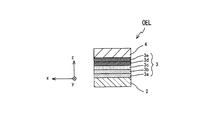
- FIG. 2 is a sectional view taken along the line CC in FIG.
- FIG. 3 is an enlarged cross-sectional view of a part of the mirror device of the organic EL panel according to the first embodiment.
- FIG. 4 is a schematic sectional view of a part of the organic EL panel showing the operation of the mirror device of the organic EL panel shown in FIG.
- FIG. 5 is a schematic sectional view of a part of a mirror device of an organic EL panel according to a modification of the first embodiment.
- FIG. 6 is a schematic sectional view of a part of a mirror device of an organic EL panel according to another modification of the first embodiment.
- FIG. 7 is a partial enlarged front view of a part of a mirror device of an organic EL panel according to another modification of the first embodiment.
- FIG. 8 is a partial enlarged front view of a part of a mirror device of an organic EL panel according to another modification of the first embodiment.
- FIG. 9 is a partial enlarged front view of a part of a mirror device of an organic EL panel according to another modification of the first embodiment.
- FIG. 10 is a partial enlarged front view of a part of a mirror device of an organic EL panel according to another modification of the first embodiment.
- FIG. 11 is a schematic sectional view of a part of the mirror device of the organic EL panel according to the second embodiment of the present invention.
- FIG. 12 is a schematic sectional view of a part of the mirror device of the organic EL panel according to the third embodiment of the present invention.
- FIG. 13 is a front view in which a part of the mirror device of the organic EL panel of Example 4 of the present invention is cut away.
- FIG. 14 is a schematic sectional view of a part of an organic EL panel according to Example 5 of the present invention.
- FIG. 15 is a schematic sectional view of a part of an organic EL panel according to Example 6 of the present invention.
- FIG. 16 is a schematic sectional view of a part of an organic EL panel according to a modification of the sixth embodiment of the present invention.
- FIG. 17 is a schematic sectional view and a partially enlarged sectional view of a part of an organic EL panel according to another modification of the sixth embodiment of the present invention.
- FIG. 18 is a schematic sectional view of a part of an organic EL panel according to Example 7 of the present invention.
- FIG. 1 shows a configuration of a mirror device that is an organic EL panel OELD of Embodiment 1 of the present invention.
- the organic EL panel OELD includes a plurality of organic EL elements OEL partitioned by banks BK on a light-transmitting flat substrate 1 such as glass or resin.
- the bank BK is made of a translucent dielectric material such as optical glass or optical resin.
- the organic EL element OEL has strip-shaped light emitting portions each extending in the y direction of the xy main surface of the substrate 1.
- the organic EL element OEL is a group of organic EL elements R, G, and B that emit light of different emission colors of red light emission R, green light emission G, and blue light emission B from the front surface 1 a of the translucent substrate 1.
- the organic EL elements R, G, and B are juxtaposed in parallel on the substrate 1.
- the organic EL elements OEL of RGB emission colors that emit red, green, and blue emission colors are arranged as a set in the x direction.
- the organic EL panel OELD further includes a plurality of metal mirror surface portions MIR distributed and disposed between the substrate 1, the bank BK, and the organic EL element OEL so as to cover them.
- the plurality of metal mirror surface portions MIR have a fine checkered pattern in which metal mirror surface portions MIR that are rectangular light reflection portions and gaps SP are alternately arranged in the x and y directions of the xy main surface. It is configured in a so-called matrix form.
- the metal mirror surface portions are indicated by hatching in an enlarged portion of the metal mirror surface portions MIR juxtaposed in a matrix form indicated by white arrows.
- the metal mirror surface portion MIR is in the organic layer 3 and at the same time is in contact with the flat translucent electrode 2.
- Each of the plurality of metal mirror surface portions MIR has an area smaller than the area of each light emitting portion of the organic EL element OEL. Therefore, when the element is driven, light from the organic EL element OEL can be extracted from the gap SP between the metal mirror surface portions MIR shown in FIG.
- each metal mirror surface portion MIR has the same shape and the same area, and a plurality of metal mirror surface portions MIR are arranged in a uniform distribution. Moreover, the shape and area of each metal mirror surface part MIR are not limited to the same as long as it has an area smaller than the area of a light emission part, and may differ.
- each of the metal mirror surface portion MIR and the gap SP is configured to have an equal interval. Therefore, if one side width of the metal mirror surface portion MIR cannot be identified with the naked eye, for example, 0.05 mm or less, and the distance between the metal mirror surface portion MIR and the organic EL element OEL is set to a short interval of 0.05 mm or less, for example, the gap SP is generated during driving.
- It can be used as a mirror that emits light from the surface and emits light from the entire surface. Further, it can function as a single mirror when the element is not driven. Further, by adjusting the luminance of the organic EL element or for each color group, red, green, and blue light are mixed at an arbitrary ratio from the front surface of the substrate 1 serving as a light extraction surface, and a single color is obtained. Light that is recognized as an emission color is emitted. Although not shown, all the organic EL elements OEL are connected to the element driving unit.
- each of the organic EL elements OEL includes a translucent electrode 2, a plurality of metal mirror surface portions MIR, an organic layer 3 including a light emitting layer, and a reflective electrode on the back surface 1b of the substrate 1 between the banks BK. 4 is laminated.
- the strip-shaped translucent electrode 2 extends in parallel in the y direction between the banks BK on the substrate 1 for each organic EL element OEL.
- the translucent electrode 2 of the organic EL element OEL is connected to the element driving unit.
- the substrate 1 on which the translucent electrode 2 is patterned is prepared, and the plurality of metal mirror surface portions MIR have a predetermined mask pattern in which the metal mirror surface portion MIR does not cause a short circuit between the adjacent translucent electrodes 2.
- the pattern in which a short circuit does not occur between the adjacent translucent electrodes 2 is a pattern on only the translucent electrode 2 in which the metal mirror surface portion MIR is not bridged between the translucent electrodes 2.
- a forward tapered structure bank BK made of a translucent dielectric material is provided along the y direction between the side surfaces of the adjacent translucent electrodes 2 by photolithography or the like.
- a predetermined organic layer 3 is formed on the translucent electrode 2 between the banks BK by an inkjet method or the like.
- a reflective electrode material is formed on the organic layer 3 between the banks BK and the top surface of the banks BK by vapor deposition or the like. Therefore, the metal mirror surface portion MIR portion disposed between the organic layer 3 and the translucent electrode 2 is obtained.
- the reflective electrode 4 becomes a common electrode having the same potential across the plurality of organic EL elements OEL.
- the mirror device of the present embodiment is a so-called bottom emission type organic that takes out light generated in the organic layer 3 from the front surface 1 a of the substrate 1 by applying a voltage between the translucent electrode 2 and the reflective electrode 4. Functions as an EL panel.
- each organic layer 3 of the organic EL element OEL in the gap portion between the metal mirror surface portions MIR typically has the translucent electrode 2 as an anode and the reflective electrode 4 as a cathode.
- a hole injection layer 3a, a hole transport layer 3b, a light emitting layer 3c, an electron transport layer 3d, and an electron injection layer 3e are laminated in order from the anode to the cathode.
- the laminated structure of the organic layer 3 it is also possible to laminate
- the organic layer 3 is not limited to these stacked structures, and may include at least a light emitting layer, for example, by adding a hole blocking layer (not shown) between the light emitting layer 3c and the electron transport layer 3d, or may be used in combination.
- a stacked structure including a charge transport layer may be employed.
- the organic layer 3 may be configured by omitting the hole transport layer 3b, the hole injection layer 3a, or the hole injection layer 3a and the electron transport layer 3d from the stacked structure. May be.
- the anode translucent electrode 2 includes ITO (Indium-tin-oxide), ZnO, ZnO—Al 2 O 3 (so-called AZO), In 2 O 3 —ZnO (so-called IZO), SnO 2 —Sb 2 O. 3 (so-called ATO), RuO 2 or the like. Furthermore, for the translucent electrode 2, it is preferable to select a material having a transmittance of at least 10% at the emission wavelength obtained from the light emitting layer.
- the translucent electrode 2 usually has a single layer structure, but can also have a laminated structure with a metal thin film.
- an appropriate metal such as tin, magnesium, indium, calcium, aluminum, silver, or an alloy thereof is used.
- Specific examples include a magnesium-silver alloy, a magnesium-indium alloy, and an aluminum-lithium alloy.
- a silver thin film having a thickness of 20 nm of the metal thin film has a transmittance of 50%.
- An Al film having a thickness of 10 nm as a metal thin film has a transmittance of 50%.
- the 20 nm-thick MgAg alloy film as the metal thin film has a transmittance of 50%.
- the hole injection layer 3a is preferably a layer containing an electron accepting compound (so-called hole transporting compound).
- the hole transporting compound is preferably a compound having an ionization potential of 4.5 eV to 6.0 eV from the viewpoint of a charge injection barrier from the anode to the hole injection layer.
- the hole transporting compound include aromatic amine derivatives, phthalocyanine derivatives typified by phthalocyanine copper (so-called CuPc), porphyrin derivatives, oligothiophene derivatives, polythiophene derivatives, benzylphenyl derivatives, tertiary amines with fluorene groups.
- Examples include linked compounds, hydrazone derivatives, silazane derivatives, silanamine derivatives, phosphamine derivatives, quinacridone derivatives, polyaniline derivatives, polypyrrole derivatives, polyphenylene vinylene derivatives, polythienylene vinylene derivatives, polyquinoline derivatives, polyquinoxaline derivatives, and carbon.
- the derivative includes, for example, an aromatic amine derivative, and includes an aromatic amine itself and a compound having an aromatic amine as a main skeleton. There may be.
- a conductive polymer obtained by polymerizing 3,4-ethylenedioxythiophene, which is a polythiophene derivative, in high molecular weight polystyrene sulfonic acid is also preferable.
- the end of the polymer of PEDOT / PSS may be capped with methacrylate or the like.
- the material of the hole transport layer 3b may be any material conventionally used as a constituent material of the hole transport layer.
- the hole transport layer is exemplified as the hole transport compound used in the hole injection layer described above. Things.
- polyvinylcarbazole derivatives polyarylamine derivatives, polyvinyltriphenylamine derivatives, polyfluorene derivatives, polyarylene derivatives, polyarylene ether sulfone derivatives containing tetraphenylbenzidine, polyarylene vinylene derivatives, polysiloxane derivatives, polythiophenes Derivatives, poly (p-phenylene vinylene) derivatives, and the like.
- These may be any of an alternating copolymer, a random polymer, a block polymer, or a graft copolymer. Further, it may be a polymer having a branched main chain and three or more terminal portions, or a so-called dendrimer.
- the light emitting layer 3c may be a red, green and blue light emitting independent light emitting layer or a mixed light emitting layer thereof, a compound having a property of transporting holes (hole transporting compound), or A compound having an electron transporting property (electron transporting compound) can also be contained.
- An organic EL material may be used as a dopant material, and a hole transporting compound, an electron transporting compound, or the like may be appropriately used as a host material. There is no particular limitation on the organic EL material, and a substance that emits light at a desired emission wavelength and has good emission efficiency may be used.
- the organic EL material may be a fluorescent material or a phosphorescent material, but it is preferable to use a phosphorescent material from the viewpoint of internal quantum efficiency.
- the light emitting layer may have a single layer structure or a multilayer structure made of a plurality of materials as desired.
- a fluorescent material may be used for the blue light emitting layer
- a phosphorescent material may be used for the green and red light emitting layers.
- a diffusion preventing layer can be provided between the light emitting layers.
- fluorescent materials blue fluorescent dyes
- examples of fluorescent materials that emit blue light include naphthalene, perylene, pyrene, chrysene, anthracene, coumarin, p-bis (2-phenylethenyl) benzene, and derivatives thereof.
- fluorescent material green fluorescent dye
- examples of the fluorescent material (green fluorescent dye) that emits green light include aluminum complexes such as quinacridone derivatives, coumarin derivatives, and Alq3 (tris (8-hydroxy-quinoline) aluminum).
- Examples of fluorescent materials that give yellow light emission include rubrene and perimidone derivatives.
- red fluorescent dyes examples include DCM (4- (dicyanomethylene) -2-methyl-6- (p-dimethylaminostyryl) -4H-pyran) compounds, benzopyran derivatives, rhodamine derivatives, benzoates. Examples thereof include thioxanthene derivatives and azabenzothioxanthene.
- the phosphorescent material is selected from, for example, the long-period periodic table (hereinafter referred to as the long-period periodic table when referring to “periodic table” unless otherwise specified).
- An organometallic complex containing a metal can be given.
- Preferred examples of the metal selected from Groups 7 to 11 of the periodic table include ruthenium, rhodium, palladium, silver, rhenium, osmium, iridium, platinum, and gold.
- a ligand in which a (hetero) aryl group such as a (hetero) arylpyridine ligand or a (hetero) arylpyrazole ligand and a pyridine, pyrazole, phenanthroline, or the like is connected is preferable.
- a pyridine ligand and a phenylpyrazole ligand are preferable.
- (hetero) aryl represents an aryl group or a heteroaryl group.
- phosphorescent materials include tris (2-phenylpyridine) iridium (so-called Ir (ppy) 3), tris (2-phenylpyridine) ruthenium, tris (2-phenylpyridine) palladium, and bis (2-phenyl).
- Pyridine) platinum tris (2-phenylpyridine) osmium, tris (2-phenylpyridine) rhenium, octaethylplatinum porphyrin, octaphenylplatinum porphyrin, octaethyl palladium porphyrin, octaphenyl palladium porphyrin, and the like.
- the light emitting layer may contain a hole transporting compound as a constituent material.
- a hole transporting compound examples include various compounds exemplified as the hole transporting compound in the hole injection layer 3a described above, for example, diphenylnaphthyl.
- Aromatic diamines represented by diamines (so-called ⁇ -NPD), including two or more tertiary amines and having two or more condensed aromatic rings substituted with nitrogen atoms, or 4,4 ′, 4 ′′- Aromatic amine compounds having a starburst structure such as tris (1-naphthylphenylamino) triphenylamine, aromatic amine compounds composed of tetramers of triphenylamine, and 2,2 ′, 7,7′-tetrakis And spiro compounds such as-(diphenylamino) -9,9'-spirobifluorene.
- ⁇ -NPD Aromatic diamines represented by diamines (so-called ⁇ -NPD), including two or more tertiary amines and having two or more condensed aromatic rings substituted with nitrogen atoms, or 4,4 ′, 4 ′′- Aromatic amine compounds having a starburst structure such as tris (1-naph
- the light emitting layer may contain an electron transporting compound as a constituent material.
- examples of low molecular weight electron transporting compounds include 2,5-bis (1-naphthyl) -1,3,4-oxadiazole (so-called BND), 2 , 5-bis (6 ′-(2 ′, 2 ′′ -bipyridyl))-1,1-dimethyl-3,4-diphenylsilole (so-called PyPySPyPy), bathophenanthroline (so-called BPhen), 2,9 -Dimethyl-4,7-diphenyl-1,10-phenanthroline (so-called BCP, bathocuproin), 2- (4-biphenylyl) -5- (p-tertiarybutylphenyl) -1,3,4-oxadiazole (So-called tBu-PBD) and 4,4′-bis (9H-carbazol-9-yl) biphenyl (so-called BND
- the electron transport layer 3d is provided for the purpose of further improving the light emission efficiency of the organic EL element, and efficiently transports electrons injected from the cathode between the electrodes to which an electric field is applied in the direction of the light emitting layer. It is formed from an electron transporting compound capable of forming
- the electron transporting compound used for the electron transport layer usually, the electron injection efficiency from the cathode or the electron injection layer 3e is high, and the injected electrons can be efficiently transported with high electron mobility.
- Use compounds examples include metal complexes of Alq3 and 10-hydroxybenzo [h] quinoline, oxadiazole derivatives, distyrylbiphenyl derivatives, silole derivatives, 3-hydroxyflavone metal complexes, and 5-hydroxyflavones.
- Metal complex benzoxazole metal complex, benzothiazole metal complex, trisbenzimidazolylbenzene, quinoxaline compound, phenanthroline derivative, 2-t-butyl-9,10-N, N′-dicyanoanthraquinonediimine, n-type hydrogenated amorphous Quality silicon carbide, n-type zinc sulfide, n-type zinc selenide and the like.
- the electron injection layer 3e plays a role of efficiently injecting electrons injected from the cathode into the electron transport layer and the light emitting layer.
- the electron injection layer 3e includes organic electron transport compounds represented by metal complexes such as nitrogen-containing heterocyclic compounds such as bathophenanthroline and aluminum complexes of 8-hydroxyquinoline. Further, the electron injection efficiency can be increased by doping the electron injection layer 3e of the organic electron transport compound with an electron donating material.
- Examples of the electron donating material include alkali metals such as sodium and cesium, alkaline earth metals such as barium and calcium, compounds thereof (CsF, Cs 2 CO 3 , Li 2 O, LiF), sodium, Alkali metals such as potassium, cesium, lithium and rubidium are used.
- a dry coating method such as a sputtering method or a vacuum deposition method, or a wet coating method such as a screen printing, a spray method, an ink jet method, a spin coating method, a gravure printing, or a roll coater method.
- a dry coating method such as a sputtering method or a vacuum deposition method
- a wet coating method such as a screen printing, a spray method, an ink jet method, a spin coating method, a gravure printing, or a roll coater method.
- the hole injection layer, the hole transport layer, and the light emitting layer are uniformly formed by a wet coating method, and the electron transport layer and the electron injection layer are sequentially formed uniformly by a dry coating method.
- a film may be formed.
- all the functional layers may be sequentially formed in a uniform film thickness by a wet coating method.
- the material of the cathode reflective electrode 4 preferably includes a metal having a low work function in order to efficiently inject electrons, for example, a suitable metal such as tin, magnesium, indium, calcium, aluminum, silver, or the like. These alloys are used. Specific examples include low work function alloy electrodes such as magnesium-silver alloy, magnesium-indium alloy, and aluminum-lithium alloy.
- the reflective electrode 4 can be formed as a single layer film or a multilayer film on the organic layer 3 by sputtering or vacuum deposition. The thickness of the reflective electrode 4 is not limited as long as the reflective action of the reflective electrode 4 is maintained.
- the operation of the organic EL panel of the mirror device will be described with reference to FIG.
- a driving voltage is applied to the light emitting layer 3c in the organic layer through the translucent electrode 2 and the reflective electrode 4, the light generated in the light emitting layer 3c passes through the translucent electrode 2 and is further reflected. After being reflected by the electrode 4, it passes through the translucent electrode 2 and about several tens of percent is taken out from the front surface of the translucent substrate 1.
- the light emitted from the light emitting layer 3c is transmitted through the translucent electrode 2 to the glass substrate 1 at a portion where the metal mirror surface portion MIR is not present, and the light L1 less than the critical angle of each interface is transmitted to the other reflective electrode 4
- the light L ⁇ b> 2 that travels toward the light passes through the light emitting layer 3 c, travels through the translucent electrode 2 to the substrate 1 at a portion without the metal mirror surface portion MIR, and the light is emitted to the front space of the substrate 1.
- the light L3 that passes through the remaining critical angle and passes through the portion without the metal mirror surface portion MIR is totally reflected and travels toward the bank BK.
- the light L4 reflected by the remaining metal mirror surface portion MIR is also directed to the bank BK.
- the light emitted from the end face of the light emitting layer 3c and the light L5 directed in the lateral direction also enter the bank BK, and are repeatedly reflected and attenuated, or pass through the translucent electrode 2 at the portion without the metal mirror surface portion MIR.
- part of the external light L6 entering from the front side space of the substrate 1 is reflected by the metal mirror surface portion MIR, and if the other portion passes through the portion without the metal mirror surface portion MIR, it is reflected by the reflective electrode 4 and emitted to the outside. Is done. Since the bank BK uses a translucent dielectric, light from adjacent elements leaks out during light emission.
- the metal mirror surface portion MIR since the metal mirror surface portion MIR has a normal element configuration, light is also emitted between the metal mirror surface portion MIR and the reflective electrode 4. For example, when the metal mirror surface portion MIR is thin, such as a film thickness of 20 nm, a certain amount of light is emitted. It has reflectivity and also has some degree of transmittance. Therefore, light is strengthened by the cavity effect between the metal mirror surface portion MIR and the reflective electrode 4, and light is output from the thin metal mirror surface portion MIR.
- FIG. 5 shows a modification of the same mirror device as the embodiment shown in FIG. 2 except that a plurality of metal mirror surface portions MIR are arranged between the substrate 1 and the translucent electrode 2.
- the metal mirror surface portion MIR has a pattern in which a short circuit does not occur between adjacent translucent electrodes 2, that is, the metal mirror surface portion MIR has a pattern only on the translucent electrode 2 that is not bridged between the translucent electrodes 2. Is formed. According to this, the mirror surface which has arrange
- FIG. 6 shows a modification of the same mirror device as the embodiment shown in FIG. 2 except that the metal bus line MBL is provided on the plurality of metal mirror surface portions MIR in the bank BK.
- the metal mirror surface portion MIR and the metal bus line MBL electrically connected to the translucent electrode 2 extend along the y direction. It is formed by stretching. Thereby, a power supply current can be efficiently supplied to the translucent electrode 2.
- FIG. 7 shows a modification of the mirror device identical to the embodiment shown in FIG. 1, except that each of the plurality of metal mirror surface portions MIR is separated and independently arranged in a so-called dot shape.
- the area of the gap SP can be set larger than the area of the metal mirror surface portion MIR, the extraction efficiency of the emitted light is improved.
- FIG. 8 shows a modification of the same mirror apparatus as that of the embodiment shown in FIG. 1 except that each of the plurality of metal mirror surface portions MIR is separated and independently arranged and the shape of the metal mirror surface portion MIR is circular.
- Various shapes can be adopted as the shape of the metal mirror surface portion MIR, regardless of the shape of the rectangle, polygon, circle, or ellipse.
- the area of the gap SP can be set differently from the area of the metal mirror surface portion MIR, the degree of freedom in designing the ratio of the reflection amount of external light and the extraction efficiency of emitted light is improved.
- the metal mirror surface portions MIR are arranged in a dot shape
- a set of shapes in which a part of each dot is connected may be used.
- FIG. 9 shows a modification of the same mirror device as that of the embodiment shown in FIG. 1 except that each of the plurality of metal mirror surface portions MIR has a strip shape extending in the y direction. Also in this case, since the area of the gap SP can be set differently from the area of the metal mirror surface portion MIR, the degree of freedom in designing the ratio of the amount of reflected external light and the efficiency of extracting emitted light is improved.
- FIG. 10 shows a modification of the same mirror device as the modification shown in FIG. 8 except that each of the plurality of metal mirror surface portions MIR has a mesh shape extending in the xy direction.
- the area of the gap SP can be set by changing the area of the metal mirror surface portion MIR, but it is necessary to form a non-existing portion of the metal mirror surface portion for insulation between the adjacent translucent electrodes. is there.
- the mirror device having the above configuration, it can be used as a mirror with illumination such as a hand mirror or a vanity mirror, and can also be used as a mirror and illumination to be attached to an advertising board or a pillar, a ceiling, etc. in order to widen the space in the store. .
- Example 2 has the same configuration as Example 1 except that an insulating film TR is provided between the organic layer 3 and the metal mirror surface portion MIR.
- an insulating film TR since there is an insulating film TR, even if there is a metal mirror surface portion MIR, that portion does not emit light, so that power consumption can be reduced. In this case, as a matter of course, there is no risk of leakage.
- the insulating film TR may be provided between the translucent electrode 2 and the metal mirror surface portion MIR, and the same effect is obtained.
- the light extraction concavo-convex structure SBP such as the water blast method or the fine sand blast method is used so as to cover the light emitting portion of the organic EL element OEL on the front surface 1a of the substrate 1.
- the uneven surface structure (not shown) has the same configuration as that of Example 1 except that the uneven surface structure (not shown) is dispersedly arranged except for the flat portion FP facing the metal mirror surface portion MIR. In this case, the output light extraction efficiency can be increased by the light extraction uneven structure SBP.
- the light extraction concavo-convex structure SBP is a rough surface or a light extraction film in which the air interface is randomly deformed in order to extract the guided light in the translucent substrate 1.
- the light that enters the translucent substrate 1 from the organic layer 3 is scattered by the concavo-convex structure SBP, a part thereof is directed to the air layer, and the rest is directed to the organic layer 3 side by changing the angle.
- the light striking the metal mirror surface portion MIR is divided into light traveling toward the air layer and light totally reflected at the flat portion FP depending on the angle.
- the light traveling toward the concavo-convex structure SBP according to the angle changes in the concavo-convex structure SBP, and is divided into light traveling toward the air layer and reflected light.
- Example 4 has the same configuration as Example 1 except that a meaningful figure is shown by the metal mirror surface portion MIR.
- the plurality of metal mirror surface portions MIR are juxtaposed in a significant pattern distribution such as “ENTER”, for example.
- Example 5 has the same configuration as Example 1 except that the thickness of adjacent metal mirror surface portions MIR is changed.
- the metal mirror surface portion MIR3 is formed to be thicker, the metal mirror surface portion MIR2 is thinner than the metal mirror surface portion MIR3, and the metal mirror surface portion MIR1 is thinner than the metal mirror surface portion MIR2.
- the metal mirror surface portions MIR are juxtaposed so that the film thicknesses of the plurality of metal mirror surface portions MIR are uniformly increased or decreased in accordance with the juxtaposition order.
- the light emission intensity (transmitted light) from the layer 3 increases accordingly, and a display with a high gradation design that changes from a mirror surface to light emission is also possible.
- a smooth emission intensity from the light emitting portion to the metal mirror surface portion MIR can be increased by gradually increasing the film thickness from the portion located at the contour of the shape toward the inside thereof. It becomes possible. Furthermore, by gradually reducing the thickness of the metal mirror surface portion MIR rather than gradually, a gradation display effect such as an inner side along the contour can be obtained.
- Example 6 will be described with reference to FIGS. 15 and 16.
- the elements denoted by the same reference numerals as those of the modification of the first embodiment (FIGS. 5 and 6) are the same, and thus the description thereof will be omitted, and the differences from the modification of the first embodiment will be mainly described.
- the metal mirror surface portion MIR on the substrate 1 Plasmon light emission can be performed by setting the period to ⁇ .
- a metal mirror surface portion MIR4 provided with unevenness of wavelength size on each substrate 1 side may be provided as a metal mirror surface portion.
- a sealing member that covers and seals the light emitting portions of the plurality of organic EL elements formed on the back surface 1b of the substrate 1 is provided.
- a glass dish-shaped transparent sealing cap may be used as the sealing member.
- the transparent sealing cap is fixed to the periphery of the light-emitting part with an adhesive so as to cover the light-emitting part, and hermetically protects the light-emitting part.
- the inside of the transparent sealing cap may be sealed by filling with an inert gas or an inert liquid.
- the sealing member a transparent resin such as polyparaxylylene, or a gas barrier sealing film composed of a multilayer of an inorganic film such as a silicon oxide film and an organic film can be used.
- a transparent resin such as polyparaxylylene
- a gas barrier sealing film composed of a multilayer of an inorganic film such as a silicon oxide film and an organic film.
- the light-emitting portion of the organic EL element is configured not to contact moisture and oxygen in the atmosphere by the sealing member.
- the translucent substrate 1 may be a quartz or glass plate, a metal plate or metal foil, a bent resin substrate, a plastic film or a sheet.
- a glass plate or a transparent plate made of a synthetic resin such as polyester, polymethacrylate, polycarbonate, or polysulfone is preferable.
- a synthetic resin substrate it is necessary to pay attention to gas barrier properties. If the gas barrier property of the substrate is too small, the organic EL element may be deteriorated by the outside air that has passed through the substrate. Therefore, a method of securing a gas barrier property by providing a dense silicon oxide film or the like on at least one surface of the synthetic resin substrate is also a preferable method.
- a so-called bottom emission type organic EL panel in which the translucent electrode 2 is formed on the back surface of the translucent substrate 1 and the light generated in the organic layer 3 is extracted from the front surface 1a of the substrate 1 is used.
- a mirror device of a so-called top emission type organic EL panel can be configured.
- top emission type Example 7 in which the film forming order of the translucent electrode and the reflective electrode is exchanged will be mainly described with respect to parts different from the Example 1 with reference to FIG. Elements indicated by the same reference numerals as those in the first embodiment are the same, and thus description thereof is omitted.
- Example 7 has the same configuration as Example 1 except that the reflective electrode 4 ⁇ / b> A, the organic layer 3, and the translucent electrode 2 are arranged in order from the substrate 1.
- the translucent electrode 2 in each of the organic EL elements of the mirror device of the top emission type organic EL panel, the translucent electrode 2 extends along the xy direction on the organic layer 3 and the metal mirror surface portion MIR. A film is formed.
- the translucent electrode 2 functions as, for example, an anode common to the plurality of organic EL elements OEL.
- a plurality of metal mirror surface portions MIR each having an area smaller than the area of the translucent electrode is formed on the translucent electrode 2.
- the reflective electrode 4A is connected to a power source (not shown). In this example, by applying a voltage between the translucent electrode 2 and the reflective electrode 4A, most of the light generated in the organic layer 3 is extracted from the translucent electrode 2 side.
- the organic layer is a light-emitting laminate, but the light-emitting laminate can also be formed by laminating inorganic material films.
- the metal mirror surface portions MIR are arranged uniformly, but although not shown, a plurality of metal mirror surface portions each having a sufficiently small area compared to the light emitting area made of the organic EL element are plural.
- the metal mirror surface portions may be randomly arranged as long as the metal mirror surface portions are visually observed so as to be uniformly disposed.
Landscapes
- Electroluminescent Light Sources (AREA)
Abstract
ミラー装置は、対向する透光性電極及び反射電極の間に積層されて発光層を含む有機層を有し且つ基板上に形成された少なくとも1つの有機EL素子を含む。ミラー装置は、透光性電極上に分散配置された複数の金属鏡面部を有する。複数の金属鏡面部の各々は透光性電極の面積より小なる面積を有する。
Description
本発明は、有機エレクトロルミネッセンス素子を含む発光機能を有するミラー装置に関する。
有機エレクトロルミネッセンス素子は、例えば、透明ガラス基板上に陽極、発光層を含む有機層及び陰極を順次積層して構成され、陽極及び陰極を介して有機層への電流注入することにより、エレクトロルミネッセンス(以下、ELと称する)を発現する発光素子である。有機EL素子は、自己発光型の面発光デバイスであり、表示装置や照明装置に利用されている。
ミラー装置としては、鏡の周囲に枠状に有機EL素子を配置して、使用者の顔等の対象物を鏡に映し出すことが可能なEL照明内蔵鏡がある(特許文献1参照)。
また、照明付きバックミラーを備えた自動車用サンバイザー組立体も提案されている(特許文献2参照)。
特許文献1に記載のEL照明内蔵鏡では、有機EL素子などの光源が鏡の周囲の枠に配置されている故に、鏡の面積が減少して、使用者が見たい顔の一部に的確に照明を与えるものではないという欠点があった。
さらに、特許文献2に記載のサンバイザー組立体においてもランプによる照明部が鏡面両側の前に直接設けられている故に、均一な発光が困難であるという問題がある。
上記のミラー装置においては、単に鏡の前後に発光部を付加して配置している故に鏡装置全体の厚みが厚くなるという欠点があった。
そこで、本発明では、光反射機能を有すると共に装置厚みが厚くなることを抑えて前面へ光を放射できるミラー装置を提供することが課題の一例として挙げられる。
本発明のミラー装置は、対向する透光性電極及び反射電極の間に積層されて発光層を含む有機層を有し且つ基板上に形成された少なくとも1つの有機EL素子を含むミラー装置であって、
前記透光性電極上に分散配置された複数の金属鏡面部を有し、
前記複数の金属鏡面部の各々は前記透光性電極の面積より小なる面積を有することを特徴とする。
前記透光性電極上に分散配置された複数の金属鏡面部を有し、
前記複数の金属鏡面部の各々は前記透光性電極の面積より小なる面積を有することを特徴とする。
以下に本発明の実施例を図面を参照しつつ説明する。
図1は、本発明の実施例1の有機ELパネルOELDであるミラー装置の構成を示す。
有機ELパネルOELDは、ガラスや樹脂などの光透過性平板の基板1上にバンクBKによって区画された複数の有機EL素子OELを含んでいる。バンクBKは例えば光学ガラスや光学樹脂などの透光性誘電体材料から形成される。有機EL素子OELは、それぞれが基板1のxy主面のy方向に伸長するストリップ形状の発光部を有する。有機EL素子OELは透光性基板1の前面1aから、赤色発光R、緑色発光G及び青色発光Bの互いに異なる発光色の光を放射する有機EL素子R、G、Bの群である。有機EL素子R、G、Bは基板1上平行に並置されている。赤、緑、青の発光色をそれぞれ発するRGB発光色の有機EL素子OELを一組としてx方向に組毎に並べられている。
有機ELパネルOELDは、さらに、基板1とバンクBK及び有機EL素子OELの間にそれ等を覆うように分散配置された複数の金属鏡面部MIRを有する。複数の金属鏡面部MIRは、図1に示すように、矩形の光反射部である金属鏡面部MIRと間隙SPとが交互にxy主面のx方向とy方向に配置された細かい市松模様状所謂マトリクス状で構成される。図1で白ヌキ矢印にて示すマトリクス状に並置された金属鏡面部MIRの拡大された部分では金属鏡面部がハッチングで示されている。金属鏡面部MIRは有機層3の中にあると同時に平板な透光性電極2と接している。
複数の金属鏡面部MIRの各々は有機EL素子OELの発光部の各々の面積より小なる面積を有する。よって、素子の駆動時には図1に示す金属鏡面部MIRの間の間隙SPとから有機EL素子OELの光が取り出せることとなる。
このように、各金属鏡面部MIRは同一形状且つ同一面積を有し、複数の金属鏡面部MIRが均一な分布で配置されている。また、各金属鏡面部MIRの形状及び面積は、発光部の面積より小なる面積を有していれば、同一に限定されず、異なっていてもよい。ここでは金属鏡面部MIRと間隙SPとの各々が均等な間隔になるように構成されている。よって、金属鏡面部MIRの一辺幅をそれぞれ肉眼で識別できない例えば0.05mm以下で金属鏡面部MIRと有機EL素子OELの間隔を例えば0.05mm以下の短い間隔とすれば、駆動時には、間隙SPから光が漏れ、あたかも全面発光する鏡として利用することができる。また、素子の非駆動時には一枚の鏡として機能できる。さらに、有機EL素子の輝度をそれぞれ又は色の群ごとに調節することにより、光取り出し面となる基板1の前面からは、赤、緑、青の光が任意の割合で混色されて単一の発光色として認識される光が放出される。なお、図示していないが、有機EL素子OELの全ては素子駆動部へ接続されている。
図2に示すように、有機EL素子OELの各々は、バンクBK間の基板1の背面1b上に、透光性電極2、複数の金属鏡面部MIR、発光層を含む有機層3、反射電極4が積層されて構成される。ストリップ形状の透光性電極2は有機EL素子OELごとに基板1上バンクBK間においてy方向に平行に伸長して並置されている。なお、図示していないが、有機EL素子OELの透光性電極2は素子駆動部へ接続されている。例えば、透光性電極2がパターン形成されている基板1を用意し、複数の金属鏡面部MIRは、金属鏡面部MIRが隣接の透光性電極2間にて短絡が生じない所定マスクパターンを用いた真空蒸着法などにより、透光性電極2のパターンの上に成膜される。かかる隣接の透光性電極2間にて短絡が生じないパターンは、金属鏡面部MIRが透光性電極2間にて架け渡されない透光性電極2のみ上のパターンである。そして、フォトリソグラフィ法などで隣接の透光性電極2の側面間にy方向に沿って透光性誘電体材料からなる順テーパー構造バンクBKを設ける。これによって、バンクBKと基板1の間にも分散配置された複数の金属鏡面部MIRを形成できる。それから、バンクBK間の透光性電極2上に所定の有機層3をインクジェット法などで成膜する。それから、反射電極材料をバンクBK間の有機層3とバンクBKの頂面上に蒸着法などにより成膜する。よって、有機層3と透光性電極2の間に配置された金属鏡面部MIRの部分が得られる。
バンクBKがバンク側面を透光性電極1側に広くした所謂、順テーパー構造を有する故に、反射電極4は複数の有機EL素子OELに亘る同電位の共通電極となる。本実施例のミラー装置は、透光性電極2と反射電極4との間に電圧を印加することにより、有機層3において生成される光を基板1の前面1aから取り出す所謂ボトムエミッション型の有機ELパネルとして機能する。
図3に示すように、金属鏡面部MIRの間の間隙部分における有機EL素子OELの各々の有機層3は、典型的には、透光性電極2が陽極で、反射電極4が陰極とした場合、陽極から陰極まで、順に、正孔注入層3a、正孔輸送層3b、発光層3c、電子輸送層3d、及び電子注入層3eが積層されて構成される。なお、有機層3の積層構成において、基板以外の構成要素を逆の順に積層することも可能である。有機層3は、これら積層構成に限定されることなく、例えば発光層3cと電子輸送層3dの間に正孔阻止層(図示せず)を追加するなど、少なくとも発光層を含み、或いは兼用できる電荷輸送層を含む積層構成としてもよい。有機層3は、上記積層構造から正孔輸送層3bを省いて構成しても、正孔注入層3aを省いて構成しても、正孔注入層3aと電子輸送層3dを省いて構成してもよい。
[透光性電極]
陽極の透光性電極2は、ITO(Indium-tin-oxide)やZnO、ZnO-Al2O3(所謂、AZO)、In2O3-ZnO(所謂、IZO)、SnO2-Sb2O3(所謂、ATO)、RuO2などにより構成され得る。さらに、透光性電極2は、発光層から得られる発光波長において少なくとも10%以上の透過率を持つ材料を選択することが好ましい。透光性電極2は通常は単層構造であるが、金属薄膜との積層構造とすることも可能である。金属薄膜の材料としては、例えば、スズ、マグネシウム、インジウム、カルシウム、アルミニウム、銀などの適当な金属又はそれらの合金が用いられる。具体例としては、マグネシウム-銀合金、マグネシウム-インジウム合金、アルミニウム-リチウム合金などが挙げられる。金属薄膜の膜厚20nmの銀薄膜は透過率50%を有する。金属薄膜としての膜厚10nmのAl膜は透過率50%を有する。同金属薄膜としての膜厚20nmのMgAg合金膜は透過率50%を有する。なお、金属薄膜を構成する場合、材料や製膜方法、条件にも依存するが、その膜厚の下限値は5nmあれば導電性を確保することができる。
陽極の透光性電極2は、ITO(Indium-tin-oxide)やZnO、ZnO-Al2O3(所謂、AZO)、In2O3-ZnO(所謂、IZO)、SnO2-Sb2O3(所謂、ATO)、RuO2などにより構成され得る。さらに、透光性電極2は、発光層から得られる発光波長において少なくとも10%以上の透過率を持つ材料を選択することが好ましい。透光性電極2は通常は単層構造であるが、金属薄膜との積層構造とすることも可能である。金属薄膜の材料としては、例えば、スズ、マグネシウム、インジウム、カルシウム、アルミニウム、銀などの適当な金属又はそれらの合金が用いられる。具体例としては、マグネシウム-銀合金、マグネシウム-インジウム合金、アルミニウム-リチウム合金などが挙げられる。金属薄膜の膜厚20nmの銀薄膜は透過率50%を有する。金属薄膜としての膜厚10nmのAl膜は透過率50%を有する。同金属薄膜としての膜厚20nmのMgAg合金膜は透過率50%を有する。なお、金属薄膜を構成する場合、材料や製膜方法、条件にも依存するが、その膜厚の下限値は5nmあれば導電性を確保することができる。
[正孔注入層]
正孔注入層3aは、電子受容性化合物(所謂、正孔輸送性化合物)を含有する層とすることが好ましい。
正孔注入層3aは、電子受容性化合物(所謂、正孔輸送性化合物)を含有する層とすることが好ましい。
正孔輸送性化合物としては、陽極から正孔注入層への電荷注入障壁の観点から4.5eV~6.0eVのイオン化ポテンシャルを有する化合物が好ましい。正孔輸送性化合物の例としては、芳香族アミン誘導体、フタロシアニン銅(所謂、CuPc)に代表されるフタロシアニン誘導体、ポルフィリン誘導体、オリゴチオフェン誘導体、ポリチオフェン誘導体、ベンジルフェニル誘導体、フルオレン基で3級アミンを連結した化合物、ヒドラゾン誘導体、シラザン誘導体、シラナミン誘導体、ホスファミン誘導体、キナクリドン誘導体、ポリアニリン誘導体、ポリピロール誘導体、ポリフェニレンビニレン誘導体、ポリチエニレンビニレン誘導体、ポリキノリン誘導体、ポリキノキサリン誘導体、カーボンなどが挙げられる。ここで誘導体とは、例えば、芳香族アミン誘導体を例にするならば、芳香族アミンそのもの及び芳香族アミンを主骨格とする化合物を含むものであり、重合体であっても、単量体であってもよい。
また、正孔輸送性化合物としては、ポリチオフェンの誘導体である3,4-エチレンジオキシチオフェンを高分子量ポリスチレンスルホン酸中で重合してなる導電性ポリマー(所謂、PEDOT/PSS)もまた好ましい。さらに、PEDOT/PSSのポリマーの末端をメタクリレートなどでキャップしたものであってもよい。
[正孔輸送層]
正孔輸送層3bの材料としては、従来、正孔輸送層の構成材料として用いられている材料であればよく、例えば、前述の正孔注入層に使用される正孔輸送性化合物として例示したものが挙げられる。また、アリールアミン誘導体、フルオレン誘導体、スピロ誘導体、カルバゾール誘導体、ピリジン誘導体、ピラジン誘導体、ピリミジン誘導体、トリアジン誘導体、キノリン誘導体、フェナントロリン誘導体、フタロシアニン誘導体、ポルフィリン誘導体、シロール誘導体、オリゴチオフェン誘導体、縮合多環芳香族誘導体、金属錯体などが挙げられる。また、例えば、ポリビニルカルバゾール誘導体、ポリアリールアミン誘導体、ポリビニルトリフェニルアミン誘導体、ポリフルオレン誘導体、ポリアリーレン誘導体、テトラフェニルベンジジンを含有するポリアリーレンエーテルサルホン誘導体、ポリアリーレンビニレン誘導体、ポリシロキサン誘導体、ポリチオフェン誘導体、ポリ(p-フェニレンビニレン)誘導体などが挙げられる。これらは、交互共重合体、ランダム重合体、ブロック重合体又はグラフト共重合体のいずれであってもよい。また、主鎖に枝分かれがあり末端部が3つ以上ある高分子や、所謂デンドリマーであってもよい。
正孔輸送層3bの材料としては、従来、正孔輸送層の構成材料として用いられている材料であればよく、例えば、前述の正孔注入層に使用される正孔輸送性化合物として例示したものが挙げられる。また、アリールアミン誘導体、フルオレン誘導体、スピロ誘導体、カルバゾール誘導体、ピリジン誘導体、ピラジン誘導体、ピリミジン誘導体、トリアジン誘導体、キノリン誘導体、フェナントロリン誘導体、フタロシアニン誘導体、ポルフィリン誘導体、シロール誘導体、オリゴチオフェン誘導体、縮合多環芳香族誘導体、金属錯体などが挙げられる。また、例えば、ポリビニルカルバゾール誘導体、ポリアリールアミン誘導体、ポリビニルトリフェニルアミン誘導体、ポリフルオレン誘導体、ポリアリーレン誘導体、テトラフェニルベンジジンを含有するポリアリーレンエーテルサルホン誘導体、ポリアリーレンビニレン誘導体、ポリシロキサン誘導体、ポリチオフェン誘導体、ポリ(p-フェニレンビニレン)誘導体などが挙げられる。これらは、交互共重合体、ランダム重合体、ブロック重合体又はグラフト共重合体のいずれであってもよい。また、主鎖に枝分かれがあり末端部が3つ以上ある高分子や、所謂デンドリマーであってもよい。
[発光層]
発光層3cは赤、緑及び青発光の独立した発光層であってもそれらの混合発光層であってもよい、また、正孔輸送の性質を有する化合物(正孔輸送性化合物)、或いは、電子輸送の性質を有する化合物(電子輸送性化合物)を含有させることもできる。有機EL材料をドーパント材料として使用し、正孔輸送性化合物や電子輸送性化合物などをホスト材料として適宜使用してもよい。有機EL材料については特に限定はなく、所望の発光波長で発光し、発光効率が良好である物質を用いればよい。
発光層3cは赤、緑及び青発光の独立した発光層であってもそれらの混合発光層であってもよい、また、正孔輸送の性質を有する化合物(正孔輸送性化合物)、或いは、電子輸送の性質を有する化合物(電子輸送性化合物)を含有させることもできる。有機EL材料をドーパント材料として使用し、正孔輸送性化合物や電子輸送性化合物などをホスト材料として適宜使用してもよい。有機EL材料については特に限定はなく、所望の発光波長で発光し、発光効率が良好である物質を用いればよい。
有機EL材料としては、任意の公知の材料を適用可能である。例えば、蛍光材料であってもよく、燐光材料であってもよいが、内部量子効率の観点から燐光材料を用いることが好ましい。発光層は単層構造としても、或いは所望により複数の材料からなる多層構造とすることもできる。例えば、青色発光層は蛍光材料を用い、緑色や赤色の発光層は燐光材料を用いるなど、様々な組み合わせで用いてもよい。また、発光層の間に拡散防止層を設けることもできる。
青色発光を与える蛍光材料(青色蛍光色素)としては、例えば、ナフタレン、ペリレン、ピレン、クリセン、アントラセン、クマリン、p-ビス(2-フェニルエテニル)ベンゼン及びそれらの誘導体などが挙げられる。
緑色発光を与える蛍光材料(緑色蛍光色素)としては、例えば、キナクリドン誘導体、クマリン誘導体、Alq3(tris (8-hydroxy-quinoline) aluminum) などのアルミニウム錯体などが挙げられる。
黄色発光を与える蛍光材料(黄色蛍光色素)としては、例えば、ルブレン、ペリミドン誘導体などが挙げられる。
赤色発光を与える蛍光材料(赤色蛍光色素)としては、例えば、DCM(4-(dicyanomethylene)-2-methyl-6-(p-dimethylaminostyryl)-4H-pyran)系化合物、ベンゾピラン誘導体、ローダミン誘導体、ベンゾチオキサンテン誘導体、アザベンゾチオキサンテンなどが挙げられる。
燐光材料としては、例えば、長周期型周期表(以下、特に断り書きの無い限り「周期表」という場合には、長周期型周期表を指すものとする。)第7~11族から選ばれる金属を含む有機金属錯体が挙げられる。周期表第7~11族から選ばれる金属として、好ましくは、ルテニウム、ロジウム、パラジウム、銀、レニウム、オスミウム、イリジウム、白金、金などが挙げられる。錯体の配位子としては、(ヘテロ)アリールピリジン配位子、(ヘテロ)アリールピラゾール配位子などの(ヘテロ)アリール基とピリジン、ピラゾール、フェナントロリンなどが連結した配位子が好ましく、特にフェニルピリジン配位子、フェニルピラゾール配位子が好ましい。ここで、(ヘテロ)アリールとは、アリール基又はヘテロアリール基を表す。
燐光材料として、具体的には、トリス(2-フェニルピリジン)イリジウム(所謂、Ir(ppy)3)、トリス(2-フェニルピリジン)ルテニウム、トリス(2-フェニルピリジン)パラジウム、ビス(2-フェニルピリジン)白金、トリス(2-フェニルピリジン)オスミウム、トリス(2-フェニルピリジン)レニウム、オクタエチル白金ポルフィリン、オクタフェニル白金ポルフィリン、オクタエチルパラジウムポルフィリン、オクタフェニルパラジウムポルフィリンなどが挙げられる。
発光層には、その構成材料として、正孔輸送性化合物を含有させてもよい。ここで、正孔輸送性化合物のうち、低分子量の正孔輸送性化合物の例としては、前述の正孔注入層3aにおける正孔輸送性化合物として例示した各種の化合物のほか、例えば、ジフェニルナフチルジアミン(所謂、α-NPD)に代表される、2個以上の3級アミンを含み2個以上の縮合芳香族環が窒素原子に置換した芳香族ジアミン類や、4,4’,4”-トリス(1-ナフチルフェニルアミノ)トリフェニルアミンなどのスターバースト構造を有する芳香族アミン化合物や、トリフェニルアミンの四量体から成る芳香族アミン化合物や、2,2’,7,7’-テトラキス-(ジフェニルアミノ)-9,9’-スピロビフルオレンなどのスピロ化合物などが挙げられる。
発光層には、その構成材料として、電子輸送性化合物を含有させてもよい。ここで、電子輸送性化合物のうち、低分子量の電子輸送性化合物の例としては、2,5-ビス(1-ナフチル)-1,3,4-オキサジアゾール(所謂、BND)や、2,5-ビス(6’-(2’,2”-ビピリジル))-1,1-ジメチル-3,4-ジフェニルシロール(所謂、PyPySPyPy)や、バソフェナントロリン(所謂、BPhen)や、2,9-ジメチル-4,7-ジフェニル-1,10-フェナントロリン(所謂、BCP、バソクプロイン)、2-(4-ビフェニリル)-5-(p-ターシャルブチルフェニル)-1,3,4-オキサジアゾール(所謂、tBu-PBD)や、4,4’-ビス(9H-カルバゾール-9-イル)ビフェニル(所謂、CBP)などが挙げられる。
[電子輸送層]
電子輸送層3dは、有機EL素子の発光効率を更に向上させることを目的として設けられるもので、電界を与えられた電極間において陰極から注入された電子を効率よく発光層の方向に輸送することができる電子輸送性化合物より形成される。
電子輸送層3dは、有機EL素子の発光効率を更に向上させることを目的として設けられるもので、電界を与えられた電極間において陰極から注入された電子を効率よく発光層の方向に輸送することができる電子輸送性化合物より形成される。
電子輸送層に用いられる電子輸送性化合物としては、通常、陰極や電子注入層3eからの電子注入効率が高く、且つ、高い電子移動度を有し注入された電子を効率よく輸送することができる化合物を用いる。このような条件を満たす化合物としては、例えば、Alq3や10-ヒドロキシベンゾ[h]キノリンの金属錯体、オキサジアゾール誘導体、ジスチリルビフェニル誘導体、シロール誘導体、3-ヒドロキシフラボン金属錯体、5-ヒドロキシフラボン金属錯体、ベンズオキサゾール金属錯体、ベンゾチアゾール金属錯体、トリスベンズイミダゾリルベンゼン、キノキサリン化合物、フェナントロリン誘導体、2-t-ブチル-9,10-N,N’-ジシアノアントラキノンジイミン、n型水素化非晶質炭化シリコン、n型硫化亜鉛、n型セレン化亜鉛などが挙げられる。
[電子注入層]
電子注入層3eは、陰極から注入された電子を効率良く電子輸送層や発光層へ注入する役割を果たす。例えば、電子注入層3eには、バソフェナントロリンなどの含窒素複素環化合物や8-ヒドロキシキノリンのアルミニウム錯体などの金属錯体に代表される有機電子輸送化合物が挙げられる。また、有機電子輸送化合物の電子注入層3eに電子供与性材料をドープすることにより、電子注入効率を高めることができる。電子供与性材料には、例としては、ナトリウムやセシウムなどのアルカリ金属、バリウムやカルシウムなどのアルカリ土類金属、それらの化合物(CsF、Cs2CO3、Li2O、LiF)や、ナトリウム、カリウム、セシウム、リチウム、ルビジウムなどのアルカリ金属などが用いられる。
電子注入層3eは、陰極から注入された電子を効率良く電子輸送層や発光層へ注入する役割を果たす。例えば、電子注入層3eには、バソフェナントロリンなどの含窒素複素環化合物や8-ヒドロキシキノリンのアルミニウム錯体などの金属錯体に代表される有機電子輸送化合物が挙げられる。また、有機電子輸送化合物の電子注入層3eに電子供与性材料をドープすることにより、電子注入効率を高めることができる。電子供与性材料には、例としては、ナトリウムやセシウムなどのアルカリ金属、バリウムやカルシウムなどのアルカリ土類金属、それらの化合物(CsF、Cs2CO3、Li2O、LiF)や、ナトリウム、カリウム、セシウム、リチウム、ルビジウムなどのアルカリ金属などが用いられる。
以上の有機層3の各々を成膜する手法として、スパッタリング法や真空蒸着法などの乾式塗布法や、スクリーン印刷、スプレー法、インクジェット法、スピンコート法、グラビア印刷、ロールコータ法などの湿式塗布法が知られている。例えば、正孔注入層、正孔輸送層、発光層を湿式塗布法で膜厚を均一に成膜して、電子輸送層及び電子注入層を、それぞれ乾式塗布法で膜厚を均一に順次成膜してもよい。また、すべての機能層を湿式塗布法で膜厚を均一に順次成膜してもよい。
[反射電極]
陰極の反射電極4の材料としては、効率良く電子注入を行う為に仕事関数の低い金属が含まれることが好ましく、例えば、スズ、マグネシウム、インジウム、カルシウム、アルミニウム、銀などの適当な金属又はそれらの合金が用いられる。具体例としては、マグネシウム-銀合金、マグネシウム-インジウム合金、アルミニウム-リチウム合金などの低仕事関数合金電極が挙げられる。反射電極4はスパッタ法や真空蒸着法などにより有機層3上に、単層膜、又は多層膜として形成され得る。なお、反射電極4の反射作用を維持する厚さであれば膜厚は限定されない。
陰極の反射電極4の材料としては、効率良く電子注入を行う為に仕事関数の低い金属が含まれることが好ましく、例えば、スズ、マグネシウム、インジウム、カルシウム、アルミニウム、銀などの適当な金属又はそれらの合金が用いられる。具体例としては、マグネシウム-銀合金、マグネシウム-インジウム合金、アルミニウム-リチウム合金などの低仕事関数合金電極が挙げられる。反射電極4はスパッタ法や真空蒸着法などにより有機層3上に、単層膜、又は多層膜として形成され得る。なお、反射電極4の反射作用を維持する厚さであれば膜厚は限定されない。
次に、図4を用いて、上記ミラー装置の有機ELパネルの動作を説明する。透光性電極2と反射電極4とを介して有機層内の発光層3cに駆動電圧が印加される時、発光層3cにおいて生成された光は透光性電極2を通過して、さらに反射電極4で反射された後に透光性電極2を通過して、数十%程度が透光性基板1の前面から取り出される。すなわち、発光層3cから発光した光は、そのうちの各界面の臨界角未満の光L1が金属鏡面部MIRのない部分にて透光性電極2を通りガラス基板1へ進み、他の反射電極4へ向かう光L2はそこで反射され発光層3cを通り金属鏡面部MIRのない部分にて透光性電極2を通り基板1へ進み、それらの光は基板1の前面空間へ放射される。残りの臨界角を超え金属鏡面部MIRのない部分を通る光L3は全反射され、バンクBKへ向かう。残りの金属鏡面部MIRで反射される光L4も、バンクBKへ向かう。なお、発光層3cの端面から発光した光や横方向へ向かう光L5もバンクBK内に入り反射を繰り返し、減衰したり、金属鏡面部MIRのない部分にて透光性電極2を通り基板1へ進み、基板1の前面空間へ放射される。一方、基板1の前面側空間から進入する外光L6は一部が金属鏡面部MIRにより反射され、他の部分が金属鏡面部MIRのない部分を通れば反射電極4で反射されて外部へ放射される。バンクBKは透光性誘電体を用いているので発光時には隣接素子からの光がもれ出てくる。
また、金属鏡面部MIR上は通常素子構成になっているので、金属鏡面部MIRと反射電極4の間でも発光しており、例えば、膜厚20nmなど金属鏡面部MIRが薄い場合は、ある程度の反射率を持ちなおかつ、ある程度の透過率もある。よって、金属鏡面部MIRと反射電極4間のキャビティ効果で光が強めあい、薄い金属鏡面部MIRから光が出力される。
以下、実施例1の変形例について図5~図10により実施例1と異なる部分について主に説明する。実施例1と同一の参照符号で示す要素は同様であるのでそれらの説明を省略する。
図5は、基板1と透光性電極2間に複数の金属鏡面部MIRを配置した以外、図2に示す実施例と同一のミラー装置の変形例を示す。金属鏡面部MIRは隣接の透光性電極2間にて短絡が生じないパターン、すなわち金属鏡面部MIRが透光性電極2間にて架け渡されない透光性電極2のみ上のパターンを有するように形成されている。これによれば、複数の金属鏡面部MIRすべてを同一平面に配置された鏡面が達成できる。
図6は、金属のバスラインMBLをバンクBK中に複数の金属鏡面部MIR上に設けた以外、図2に示す実施例と同一のミラー装置の変形例を示す。この場合、バンクBKに埋設された透光性電極2の各々の端側上には、金属鏡面部MIRと透光性電極2に電気的に接続された金属のバスラインMBLがy方向に沿って伸長して形成されている。これにより、透光性電極2に電源電流を効率よく供給することができる。
図7は、複数の金属鏡面部MIRの各々を分離し独立させて、所謂ドット状に配置した以外、図1に示す実施例と同一のミラー装置の変形例を示す。この場合、金属鏡面部MIRの面積に比べ間隙SPの面積を大きく設定できる故に、発光光の取り出し効率が向上する。
図8は、複数の金属鏡面部MIRの各々を分離して独立させて配置し金属鏡面部MIRの形状を円形とした以外、図1に示す実施例と同一のミラー装置の変形例を示す。金属鏡面部MIRの形状には、矩形や多角形や円形や楕円の形状にとらわれず、様々な形状を採用できる。この場合、金属鏡面部MIRの面積に比べ間隙SPの面積を変化させて設定できる故に、外光光の反射量や発光光の取り出し効率の割合の設計の自由度が向上する。
上記した金属鏡面部MIRをドット状に配置する例において、各ドットの一部を連結した形状の集合とすることもできる。
図9は、複数の金属鏡面部MIRの各々をy方向に伸長するストリップ形状とした以外、図1に示す実施例と同一のミラー装置の変形例を示す。この場合も、金属鏡面部MIRの面積に比べ間隙SPの面積を変化させて設定できる故に、外光光の反射量や発光光の取り出し効率の割合の設計自由度が向上する。
図10は、複数の金属鏡面部MIRの各々をxy方向に拡張するメッシュ形状とした以外、図8に示す変形例と同一のミラー装置の変形例を示す。この場合は、金属鏡面部MIRの面積に比べ間隙SPの面積を変化させて設定できるけれども、隣接する透光性電極の間に、絶縁のための金属鏡面部の非存在部を形成する必要がある。
以上の構成のミラー装置によれば、手鏡やバニティミラーなど照明付鏡として利用でき、さらに、広告用ボードや、店舗内の空間を広く見せるために柱、天井などに取り付ける鏡兼照明として利用できる。
以下、実施例2について図11によって実施例1と異なる部分について主に説明する。実施例1と同一の参照符号で示す要素は同様であるのでそれらの説明を省略する。
図11に示すように、実施例2は、有機層3と金属鏡面部MIRの間に絶縁膜TRを設けたした以外、実施例1と同様な構成を有する。この場合は絶縁膜TRがある故に金属鏡面部MIRがあってもその部分が発光しないので、消費電力の削減がはかれる。なお、この場合は当然のことながらリークの危険性はまったくない。さらに、図示しないが、実施例2の変形例では、絶縁膜TRを透光性電極2と金属鏡面部MIRの間に設けてもよく、同様の効果が得られる。
以下、実施例3について図12によって実施例1と異なる部分について主に説明する。実施例1と同一の参照符号で示す要素は同様であるのでそれらの説明を省略する。
図12に示すように、実施例3は、基板1の前面1aに、有機EL素子OELの発光部を覆うように、これを超える面積で光取り出し凹凸構造SBP例えばウォーターブラスト法や微細なサンドブラスト法などで凹凸表面構造(図示せず)が金属鏡面部MIRに対向する平坦部分FPを除き分散配置されている以外、実施例1と同様な構成を有する。この場合、光取り出し凹凸構造SBPにより出力光の取り出し効率を上げることができる。かかる光取り出し凹凸構造SBPは透光性基板1内の導波光を取り出すため空気界面をランダムに異形化した粗面又は光取り出しフィルムである。有機層3から透光性基板1へ入った光は、凹凸構造SBPで散乱し、一部は空気層へ、残りは角度を変えて有機層3側へ向かう。有機層3側へ向かった光のうち、金属鏡面部MIRに当たった光は、角度によって平坦部分FPで、空気層へ向かう光と全反射される光に分かれる。角度によって凹凸構造SBPへ向かった光は、凹凸構造SBPで角度が変わり、空気層へ向かう光と反射される光に分かれる。
以下、実施例4について図13によって実施例1と異なる部分について主に説明する。実施例1と同一の参照符号で示す要素は同様であるのでそれらの説明を省略する。
図13に示すように、実施例4は、金属鏡面部MIRで意味のある図形を示す以外、実施例1と同様な構成を有する。この場合、複数の金属鏡面部MIRは、例えば「ENTER」などの有意なパターン分布で並置されている。金属鏡面部MIRの大きさを同じにし、間隔を所定の間隔とし、全体として、意味のある図形にすることにより、鏡面による意匠性の高い表示も可能となる。
以下、実施例5について図14によって実施例1と異なる部分について主に説明する。実施例1と同一の参照符号で示す要素は同様であるのでそれらの説明を省略する。
図14に示すように、実施例5は、隣接する金属鏡面部MIR同士の厚みを変化させる以外、実施例1と同様な構成を有する。この場合、金属鏡面部MIR3は膜厚が厚く、金属鏡面部MIR2は金属鏡面部MIR3より膜厚が薄く、金属鏡面部MIR1は金属鏡面部MIR2より膜厚が更に薄く、形成されている。このように複数の金属鏡面部MIRの各々の膜厚が並置順序に応じて一様増加又は減少するように金属鏡面部MIRが並置されていることにより、薄くなる金属鏡面部の並ぶ方向に有機層3からの発光強度(透過光)がそれに応じて増加して、鏡面から発光に変化するグラデーションの意匠性の高い表示も可能となる。なお、1つの金属鏡面部MIRについても、その形状の輪郭に位置する部位からその内側に向かって、徐々にその膜厚を厚くすることで、発光部から金属鏡面部MIRへ滑らかな発光強度が可能となる。さらに、徐々にではなく、金属鏡面部MIRの厚みを部分的に薄くすることで、例えば輪郭にそった内側などグラデーション表示効果が得られる。
次に、図15及び図16を参照して、実施例6を説明する。実施例1の変形例(図5及び図6)と同一の参照符号で示す要素は同様であるのでそれらの説明を省略して、実施例1の変形例と異なる部分について、主に説明する。
図15及び図16に示すように、発光ピーク波長(以下λという)の発光スペクトル分布の発光材料からなる発光層を含む有機層3を備えた素子の場合、基板1上の金属鏡面部MIRの周期をλとすることによりプラズモン発光を行うことができる。
また、更なる変形例のミラー装置として、図17に示すように、金属鏡面部として各々の基板1側に波長サイズの凹凸を設けた金属鏡面部MIR4を設けてもよい。
さらに、図示しないが、上記の何れの形態のミラー装置においても、基板1の背面1bに形成された複数の有機EL素子の発光部を覆い且つこれらを封止する封止部材が設けられている。封止部材には、ガラス製の皿状の透明封止キャップが用いられ得る。透明封止キャップは発光部を覆うようにその周囲に接着剤を介して固定され発光部を密閉保護する。透明封止キャップの内部は不活性気体又は不活性液体を充填することにより封止されてもよい。また、封止部材として、ポリパラキシリレンなどの透明樹脂や、シリコン酸化膜などの無機膜と有機膜の多層からなるガスバリア性封止膜が用いられ得る。このように、封止部材により有機EL素子の発光部は大気中の水分及び酸素と接しないように構成されていることが好ましい。
なお、上記した実施例においては、透光性基板1として、石英やガラスの板、金属板や金属箔、曲げられる樹脂基板、プラスチックフィルムやシートなどを用いることができる。特にガラス板や、ポリエステル、ポリメタクリレート、ポリカーボネート、ポリスルホンなどの合成樹脂の透明板が好ましい。合成樹脂基板を使用する場合にはガスバリア性に留意する必要がある。基板のガスバリア性が小さすぎると、基板を通過した外気により有機EL素子が劣化することがあるので好ましくない。よって、合成樹脂基板の少なくとも片面に緻密なシリコン酸化膜などを設けてガスバリア性を確保する方法も好ましい方法の一つである。
さらに、上記実施例では、透光性電極2が透光性基板1の背面上に形成されて有機層3において生成される光を基板1の前面1aから取り出す所謂ボトムエミッション型の有機ELパネルを説明したが、更なる実施例においては、所謂トップエミッションタイプの有機ELパネルのミラー装置も構成できる。
以下、透光性電極と反射電極の成膜順序を入れ替えたトップエミッションタイプの実施例7について図18によって実施例1と異なる部分について主に説明する。実施例1と同一の参照符号で示す要素は同様であるのでそれらの説明を省略する。
図18に示すように、実施例7は、基板1から近い順に反射電極4A、有機層3及び透光性電極2となるように配置した以外、実施例1と同様な構成を有する。図18に示すように、トップエミッションタイプの有機ELパネルのミラー装置の有機EL素子の各々において、透光性電極2は有機層3上と金属鏡面部MIR上においてxy方向に沿って拡張して成膜されている。透光性電極2は複数の有機EL素子OELの共通の例えば陽極として機能する。各々が透光性電極の面積より小なる面積を有する複数の金属鏡面部MIRは透光性電極2に形成されている。なお、反射電極4Aは図示しない電源に接続されている。この例では、透光性電極2と反射電極4Aの間に電圧を印加することにより、有機層3において生成される光がほとんど透光性電極2側から取り出される。
また、上記の実施例では有機層を発光積層体としているが、無機材料膜の積層によっても発光積層体を構成できる。
また、上記実施例では複数の有機EL素子R、G、Bを並置した例で示したが、これには限定されず、各々が複数の発光層からなるタンデム構造など発光層の積層構造や混合発光層を利用した複数の白色発光有機EL素子を並置した場合でも同様の効果が得られる。
さらにまた、上記実施例では金属鏡面部MIRが均等に配置されていることとしているが、図示しないが、有機EL素子からなる発光面積に比べそれぞれの金属鏡面部の面積が十分小さい場合は複数の金属鏡面部が一様に配置されているように目視されるならば金属鏡面部はランダムに配置されてもよい。
1 基板
2 透光性電極
3 有機層
3a 正孔注入層
3b 正孔輸送層
3c 発光層
3d 電子輸送層
3e 電子注入層
4 反射電極
BK バンク
MBL バスライン
MIR 金属鏡面部
OEL 有機EL素子
2 透光性電極
3 有機層
3a 正孔注入層
3b 正孔輸送層
3c 発光層
3d 電子輸送層
3e 電子注入層
4 反射電極
BK バンク
MBL バスライン
MIR 金属鏡面部
OEL 有機EL素子
Claims (10)
- 対向する透光性電極及び反射電極の間に積層されて発光層を含む有機層を有し且つ基板上に形成された少なくとも1つの有機EL素子を含むミラー装置であって、
前記透光性電極上に分散配置された複数の金属鏡面部を有し、
前記複数の金属鏡面部の各々は前記透光性電極の面積より小なる面積を有することを特徴とするミラー装置。 - 前記複数の金属表面部は、一様に分布されていることを特徴とする請求項1に記載のミラー装置。
- 前記複数の金属鏡面部の各々は同一形状且つ同一面積を有することを特徴とする請求項2に記載のミラー装置。
- 前記複数の金属鏡面部の各々の膜厚が並置順序に応じて一様増加又は減少するように、並置されていることを特徴とする請求項2に記載のミラー装置。
- 前記複数の金属鏡面部は一定の間隔でマトリクス状に並置されていることを特徴とする請求項3に記載のミラー装置。
- 前記複数の金属鏡面部の各々はストリップ形状を有し、前記複数の金属鏡面部は一定の間隔でストライプ状に並置されていることを特徴とする請求項2に記載のミラー装置。
- 前記基板が透光性基板であり、前記透光性電極が前記透光性基板上に形成されていることを特徴とする請求項2に記載のミラー装置。
- 前記複数の金属鏡面部は、隣接するもの同士の間隔が前記発光層で発光するピーク波長と同一となるように並置されていることを特徴とする請求項2に記載のミラー装置。
- 前記基板上に形成され且つ前記有機EL素子を区画する透光性誘電体バンクを更に有し、前記透光性誘電体バンクと前記基板の間に分散配置された少なくとも1つの金属鏡面部を有することを特徴とする請求項2に記載のミラー装置。
- 前記複数の金属鏡面部は有意なパターン分布で配置されていることを特徴とする請求項1に記載のミラー装置。
Priority Applications (1)
| Application Number | Priority Date | Filing Date | Title |
|---|---|---|---|
| PCT/JP2012/078971 WO2014073072A1 (ja) | 2012-11-08 | 2012-11-08 | ミラー装置 |
Applications Claiming Priority (1)
| Application Number | Priority Date | Filing Date | Title |
|---|---|---|---|
| PCT/JP2012/078971 WO2014073072A1 (ja) | 2012-11-08 | 2012-11-08 | ミラー装置 |
Publications (1)
| Publication Number | Publication Date |
|---|---|
| WO2014073072A1 true WO2014073072A1 (ja) | 2014-05-15 |
Family
ID=50684210
Family Applications (1)
| Application Number | Title | Priority Date | Filing Date |
|---|---|---|---|
| PCT/JP2012/078971 WO2014073072A1 (ja) | 2012-11-08 | 2012-11-08 | ミラー装置 |
Country Status (1)
| Country | Link |
|---|---|
| WO (1) | WO2014073072A1 (ja) |
Cited By (1)
| Publication number | Priority date | Publication date | Assignee | Title |
|---|---|---|---|---|
| WO2021176539A1 (ja) * | 2020-03-02 | 2021-09-10 | シャープ株式会社 | 表示装置 |
Citations (6)
| Publication number | Priority date | Publication date | Assignee | Title |
|---|---|---|---|---|
| WO2005034586A1 (ja) * | 2003-10-02 | 2005-04-14 | Kabushiki Kaisha Toyota Jidoshokki | 電界発光素子 |
| JP2006156205A (ja) * | 2004-11-30 | 2006-06-15 | Meiki Plastics Co Ltd | 発光装置及び発光装置用反射部材 |
| JP2007080579A (ja) * | 2005-09-12 | 2007-03-29 | Toyota Industries Corp | 面発光装置 |
| JP2008041341A (ja) * | 2006-08-03 | 2008-02-21 | Seiko Epson Corp | 発光装置およびその製造方法並びに電子機器 |
| JP2008192314A (ja) * | 2007-01-31 | 2008-08-21 | Optrex Corp | 有機el表示装置およびその製造方法 |
| WO2011155306A1 (ja) * | 2010-06-07 | 2011-12-15 | Necライティング株式会社 | 有機エレクトロルミネッセンス照明装置 |
-
2012
- 2012-11-08 WO PCT/JP2012/078971 patent/WO2014073072A1/ja active Application Filing
Patent Citations (6)
| Publication number | Priority date | Publication date | Assignee | Title |
|---|---|---|---|---|
| WO2005034586A1 (ja) * | 2003-10-02 | 2005-04-14 | Kabushiki Kaisha Toyota Jidoshokki | 電界発光素子 |
| JP2006156205A (ja) * | 2004-11-30 | 2006-06-15 | Meiki Plastics Co Ltd | 発光装置及び発光装置用反射部材 |
| JP2007080579A (ja) * | 2005-09-12 | 2007-03-29 | Toyota Industries Corp | 面発光装置 |
| JP2008041341A (ja) * | 2006-08-03 | 2008-02-21 | Seiko Epson Corp | 発光装置およびその製造方法並びに電子機器 |
| JP2008192314A (ja) * | 2007-01-31 | 2008-08-21 | Optrex Corp | 有機el表示装置およびその製造方法 |
| WO2011155306A1 (ja) * | 2010-06-07 | 2011-12-15 | Necライティング株式会社 | 有機エレクトロルミネッセンス照明装置 |
Cited By (1)
| Publication number | Priority date | Publication date | Assignee | Title |
|---|---|---|---|---|
| WO2021176539A1 (ja) * | 2020-03-02 | 2021-09-10 | シャープ株式会社 | 表示装置 |
Similar Documents
| Publication | Publication Date | Title |
|---|---|---|
| KR101634814B1 (ko) | 유기 발광 소자, 및 이것을 구비한 표시장치 및 조명 장치 | |
| US10090488B2 (en) | Mirror device having a light-transmissive substrate | |
| US10109819B2 (en) | Light-emitting device | |
| JP5676867B2 (ja) | 有機エレクトロルミネッセンス素子 | |
| KR20110107292A (ko) | 유기 일렉트로 루미네선스 장치 | |
| JP2008047340A (ja) | 有機エレクトロルミネッセンス素子 | |
| US9130185B2 (en) | Organic light emitting diode | |
| KR20130030187A (ko) | 유기 전계 발광 소자, 표시 장치 및 조명 장치 | |
| JP2016164855A (ja) | 発光装置並びにこれを備えた表示装置、照明装置および電子機器 | |
| JP6433963B2 (ja) | ミラー装置 | |
| JP5912174B2 (ja) | 有機エレクトロルミネッセンスパネル及びその製造方法 | |
| JP2019192448A (ja) | 表示装置 | |
| JP2014225328A (ja) | 発光デバイス、表示装置、及び照明装置 | |
| WO2014073072A1 (ja) | ミラー装置 | |
| JP6340404B2 (ja) | 発光装置 | |
| JP2018139223A (ja) | 発光装置 | |
| JP2023052941A (ja) | 発光装置 | |
| JP6185109B2 (ja) | 有機エレクトロルミネッセンスパネル及びその製造方法 | |
| WO2013150593A1 (ja) | 有機エレクトロルミネッセンスパネル及びその製造方法 | |
| WO2014013566A1 (ja) | ミラー装置 | |
| CN117356183A (zh) | 显示装置及显示面板 | |
| KR20170131965A (ko) | 유기 발광 소자 및 그를 이용한 유기 발광 표시 장치 |
Legal Events
| Date | Code | Title | Description |
|---|---|---|---|
| 121 | Ep: the epo has been informed by wipo that ep was designated in this application |
Ref document number: 12888095 Country of ref document: EP Kind code of ref document: A1 |
|
| NENP | Non-entry into the national phase |
Ref country code: DE |
|
| 122 | Ep: pct application non-entry in european phase |
Ref document number: 12888095 Country of ref document: EP Kind code of ref document: A1 |
|
| NENP | Non-entry into the national phase |
Ref country code: JP |