WO2014073041A1 - ホログラム光ピックアップ装置、ホログラム装置、高速撮像装置 - Google Patents
ホログラム光ピックアップ装置、ホログラム装置、高速撮像装置 Download PDFInfo
- Publication number
- WO2014073041A1 WO2014073041A1 PCT/JP2012/078776 JP2012078776W WO2014073041A1 WO 2014073041 A1 WO2014073041 A1 WO 2014073041A1 JP 2012078776 W JP2012078776 W JP 2012078776W WO 2014073041 A1 WO2014073041 A1 WO 2014073041A1
- Authority
- WO
- WIPO (PCT)
- Prior art keywords
- light
- pickup device
- optical pickup
- optical
- image sensor
- Prior art date
- Legal status (The legal status is an assumption and is not a legal conclusion. Google has not performed a legal analysis and makes no representation as to the accuracy of the status listed.)
- Ceased
Links
Images







Classifications
-
- G—PHYSICS
- G11—INFORMATION STORAGE
- G11B—INFORMATION STORAGE BASED ON RELATIVE MOVEMENT BETWEEN RECORD CARRIER AND TRANSDUCER
- G11B7/00—Recording or reproducing by optical means, e.g. recording using a thermal beam of optical radiation by modifying optical properties or the physical structure, reproducing using an optical beam at lower power by sensing optical properties; Record carriers therefor
- G11B7/12—Heads, e.g. forming of the optical beam spot or modulation of the optical beam
- G11B7/135—Means for guiding the beam from the source to the record carrier or from the record carrier to the detector
- G11B7/1365—Separate or integrated refractive elements, e.g. wave plates
-
- G—PHYSICS
- G11—INFORMATION STORAGE
- G11B—INFORMATION STORAGE BASED ON RELATIVE MOVEMENT BETWEEN RECORD CARRIER AND TRANSDUCER
- G11B7/00—Recording or reproducing by optical means, e.g. recording using a thermal beam of optical radiation by modifying optical properties or the physical structure, reproducing using an optical beam at lower power by sensing optical properties; Record carriers therefor
- G11B7/12—Heads, e.g. forming of the optical beam spot or modulation of the optical beam
- G11B7/13—Optical detectors therefor
-
- G—PHYSICS
- G03—PHOTOGRAPHY; CINEMATOGRAPHY; ANALOGOUS TECHNIQUES USING WAVES OTHER THAN OPTICAL WAVES; ELECTROGRAPHY; HOLOGRAPHY
- G03H—HOLOGRAPHIC PROCESSES OR APPARATUS
- G03H1/00—Holographic processes or apparatus using light, infrared or ultraviolet waves for obtaining holograms or for obtaining an image from them; Details peculiar thereto
- G03H1/26—Processes or apparatus specially adapted to produce multiple sub- holograms or to obtain images from them, e.g. multicolour technique
-
- G—PHYSICS
- G11—INFORMATION STORAGE
- G11B—INFORMATION STORAGE BASED ON RELATIVE MOVEMENT BETWEEN RECORD CARRIER AND TRANSDUCER
- G11B7/00—Recording or reproducing by optical means, e.g. recording using a thermal beam of optical radiation by modifying optical properties or the physical structure, reproducing using an optical beam at lower power by sensing optical properties; Record carriers therefor
- G11B7/004—Recording, reproducing or erasing methods; Read, write or erase circuits therefor
- G11B7/0065—Recording, reproducing or erasing by using optical interference patterns, e.g. holograms
-
- G—PHYSICS
- G11—INFORMATION STORAGE
- G11B—INFORMATION STORAGE BASED ON RELATIVE MOVEMENT BETWEEN RECORD CARRIER AND TRANSDUCER
- G11B7/00—Recording or reproducing by optical means, e.g. recording using a thermal beam of optical radiation by modifying optical properties or the physical structure, reproducing using an optical beam at lower power by sensing optical properties; Record carriers therefor
- G11B7/007—Arrangement of the information on the record carrier, e.g. form of tracks, actual track shape, e.g. wobbled, or cross-section, e.g. v-shaped; Sequential information structures, e.g. sectoring or header formats within a track
- G11B7/00772—Arrangement of the information on the record carrier, e.g. form of tracks, actual track shape, e.g. wobbled, or cross-section, e.g. v-shaped; Sequential information structures, e.g. sectoring or header formats within a track on record carriers storing information in the form of optical interference patterns, e.g. holograms
-
- G—PHYSICS
- G11—INFORMATION STORAGE
- G11B—INFORMATION STORAGE BASED ON RELATIVE MOVEMENT BETWEEN RECORD CARRIER AND TRANSDUCER
- G11B7/00—Recording or reproducing by optical means, e.g. recording using a thermal beam of optical radiation by modifying optical properties or the physical structure, reproducing using an optical beam at lower power by sensing optical properties; Record carriers therefor
- G11B7/08—Disposition or mounting of heads or light sources relatively to record carriers
- G11B7/085—Disposition or mounting of heads or light sources relatively to record carriers with provision for moving the light beam into, or out of, its operative position or across tracks, otherwise than during the transducing operation, e.g. for adjustment or preliminary positioning or track change or selection
- G11B7/08547—Arrangements for positioning the light beam only without moving the head, e.g. using static electro-optical elements
- G11B7/08564—Arrangements for positioning the light beam only without moving the head, e.g. using static electro-optical elements using galvanomirrors
Definitions
- the present invention relates to a hologram optical pickup device, a hologram device, a high-speed imaging device, and the like.
- the Blu-ray Disc standard using a blue-violet semiconductor laser has made it possible to commercialize an optical disc having a recording density of about 50 GB even for consumer use.
- HDD Hard Disk Drive
- Hologram recording technology is a method in which signal light having page data information two-dimensionally modulated by a spatial light modulator is superimposed on reference light inside the recording medium, and the interference fringe pattern generated at that time is placed in the recording medium. This is a technique for recording information on a recording medium by causing refractive index modulation.
- the hologram recorded in the recording medium acts like a diffraction grating to generate diffracted light. This diffracted light is reproduced as the same light including the recorded signal light and phase information.
- Regenerated signal light is detected two-dimensionally using an image sensor such as a CMOS or CCD.
- an image sensor such as a CMOS or CCD.
- the hologram recording technique enables two-dimensional information to be recorded on the optical recording medium at once by one hologram and further reproduces this information. Since the page data can be overwritten, large-capacity and high-speed information recording / reproduction can be achieved.
- Patent Document 1 describes that “the achievable density / capacity of a holographic medium is increased” as a problem, and “a hologram is spatially caused by a partial spatial overlap between adjacent stacks of holograms” as a solution. Multiplexing methods and devices are disclosed, each stack further taking full advantage of another multiplexing technique such as angle, wavelength, phase code, peritropy, or fractal multiplexing. An amount equal to the beam waist of the signal light that writes the hologram separates the individual stacks of holograms, and at the time of reproduction, a hologram and its adjacent holograms are all read out simultaneously.
- JP-A-2005-233998 describes that "a plurality of diffracted lights are simultaneously generated in different directions by irradiating a single reproducing reference beam, and these are simultaneously received by a plurality of image sensors to reproduce a record.”
- Another background art is WO2012-053198.
- This publication describes that "the second reference light is branched into a plurality of parts, each of which has a different phase change and is reproduced by detecting the interfered light with a plurality of CCDs".
- Patent Document 1 increases the achievable density / capacity of the holographic medium as described above.
- high speed reproduction is a problem in the hologram system.
- the reproduction speed depends on the number of pixels of the image sensor and the frame rate, and it is difficult for the hologram system using page data with high pixels to increase the reproduction speed.
- Patent Documents 2 and 3 there are only a plurality of light receiving surfaces of the imaging device, and there is a problem in high-speed reproduction of a large number of pages.
- an object of the present invention is to provide a hologram optical pickup device, a hologram device, and a high-speed imaging device that can realize high-speed reproduction.
- an optical pickup device that reproduces information from a recording medium in which an interference pattern of signal light and reference light is recorded as a hologram, and includes a laser emitting portion that emits reference light, and an output from the laser emitting portion. And a detection optical unit that detects the reproduction light diffracted from the optical information recording medium based on the reference light.
- the detection optical unit includes a plurality of detection optical units.
- FIG. 2 is a diagram illustrating an optical system in Embodiment 1.
- FIG. 3 is a diagram illustrating a method for detecting an image sensor in the first embodiment.
- 3 is a timing chart of an image sensor and a galvanometer mirror in the conventional hologram system in Embodiment 1.
- FIG. 3 is a timing chart of an image sensor and a galvanometer mirror in the hologram system in Embodiment 1.
- FIG. 5 is a diagram illustrating another image sensor in Example 1.
- FIG. 6 is a diagram illustrating an optical system in Example 2. It is a figure explaining the division
- FIG. FIG. 6 is a diagram illustrating an optical system in Example 3.
- the imaging device in Example 3 is an imaging device and timing chart in one hologram system.
- FIG. 10 is a diagram illustrating a timing chart of an image pickup element and a high-speed polarization control element in a hologram system in Example 3.
- 6 is a diagram showing a hologram optical information recording / reproducing apparatus in Example 4.
- FIG. It is a figure explaining the optical system in another Example.
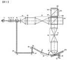
- FIG. 1 shows an optical system of a two-beam angle multiplexing hologram pickup apparatus according to a first embodiment of the present invention.
- the light beam emitted from the light source 11 passes through the collimator lens 12 and is converted into a desired beam diameter, and then enters the polarization control element 14 through the shutter 13.
- the light beam is converted into P-polarized light and S-polarized light by the polarization control element 14.
- the polarization control element 14 is an element that converts outgoing polarized light into predetermined polarized light according to recording or reproduction. In this embodiment, it is assumed that P-polarized light and S-polarized light are converted during recording, and S-polarized light is converted during reproduction.
- the light beam emitted from the polarization control element 14 enters the PBS prism 15, P-polarized light is transmitted, and S-polarized light is reflected.
- the light beam transmitted through the PBS prism is called signal light, and the reflected light beam is called reference light.
- the signal light transmitted through the PBS prism 15 is converted into a desired beam diameter by the beam expander 25.
- the signal light transmitted through the beam expander 25 enters the spatial light modulator 29 through the phase mask 26, the relay lens 27, and the PBS prism 28, and is added with two-dimensional data.
- the spatial light modulator 29 is an optical element that adds two-dimensional data to signal light.
- the signal light to which information is added by the spatial light modulator 29 is reflected by the PBS prism 28, and is condensed in the optical information recording medium 300 through the relay lens 30, the spatial filter 31, and the objective lens 32.
- the reference light reflected by the PBS prism 15 reflects the mirrors 36 and 37 and enters the galvano mirror 38.
- the galvanometer mirror 38 is an element capable of controlling the mirror angle. By using this galvanometer mirror 38, the angle of incidence of the reference light on the optical information recording medium can be changed, so that angle multiplexing can be realized.
- the reference light reflected from the galvanometer mirror 38 enters the optical information recording medium 300 through the scanner lens 39.
- an interference fringe pattern is formed in the optical information recording medium 300.
- This interference fringe pattern is recorded as a hologram in the recording medium.
- a hologram in which two-dimensional data is recorded is called a page, and a region where pages are multiplexed is called a book.
- the shutter 13 is closed and the information to be recorded next is displayed by the spatial light modulator 29.
- the galvanometer mirror 38 is rotated by a small angle, and the incident angle of the reference light to the optical information recording medium 300 is changed.
- the shutter 13 is opened, the next recorded information is recorded at an angle different from the angle previously recorded in the same book of the optical information recording medium 300. By repeating this, angle multiplex recording is performed.
- the light beam emitted from the light source 11 passes through the collimator lens 12 and is converted into a desired beam diameter, and then passes through the shutter 13 and enters the polarization control element 14. Then, the light beam is converted into S-polarized light by the polarization control element 14 and reflected by the PBS prism 15.
- the light beam reflected from the PBS prism 15 is referred to as reference light.
- the reference light reflected by the PBS prism 15 is reflected by the mirrors 36 and 37 and enters the galvanometer mirror 38.
- the reference light reflected by the galvanometer mirror 38 enters the galvanometer mirror 50 through the scanner lens 39, the optical information recording medium 300, and the quarter wavelength plate 51.
- the galvanometer mirror 50 is controlled so that the incident reference light is substantially perpendicular to the galvanometer mirror 50. For this reason, the incident reference light is reflected in a substantially opposite direction, and reenters the optical information recording medium 300 through the quarter-wave plate 51.
- reproduction light (diffracted light of the reference light) having predetermined information is generated in the direction of the objective lens 32 from the recording area.
- the high-speed polarization control element 100 of this embodiment is a liquid crystal element such as a ferroelectric liquid crystal, and is an element capable of converting outgoing polarized light into P-polarized light and S-polarized light at high speed.
- the reproduction light emitted from the high-speed polarization control element 100 enters the image sensor 102 or the image sensor 103 via the PBS prism 101. Then, reproduction image data is generated based on the reproduction light incident on the image sensor 102 or the image sensor 103. Next, the galvanometer mirrors 38 and 50 rotate by a small amount, the incident angle of the reference light to the optical information recording medium 300 is changed, and the reproduction light of the next page enters the image sensor 103 or the image sensor 102. Then, reproduction image data is generated based on the reproduction light incident on the image sensor 103 or the image sensor 102. As a result, the reproduction image data of the angle-multiplexed page in the optical information recording medium is generated.
- FIG. 2 is a diagram illustrating a detection method of the image sensors 102 and 103 according to the present embodiment.
- FIG. 2A shows a case where odd pages are reproduced
- FIG. 2B shows a case where even pages are reproduced.
- the high-speed polarization control element 100 When reproducing odd pages, the high-speed polarization control element 100 emits P-polarized light. Therefore, the reproduction light emitted from the high-speed polarization control element 100 passes through the PBS prism 101 and enters the imaging element 101 (FIG. 2A). When reproducing even pages, the high-speed polarization control element 100 emits S-polarized light. Therefore, the reproduction light emitted from the high-speed polarization control element 100 is reflected by the PBS prism 101 and enters the image sensor 102. As described above, the present embodiment is characterized in that a plurality of image sensors are switched.
- the image pickup device of the present embodiment will be described by a single buffer system in which one buffer is mounted.
- the same effect can be obtained even in a multi-buffer system in which two or more buffers are mounted.
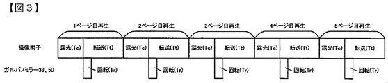
- FIG. 3 shows a timing chart of the image sensor and the galvanometer mirrors 38 and 50 in the conventional hologram system using one image sensor. Note that the description will be given with the reproduction of five pages, but the actual number of multiplexing is not limited to this.
- the image sensor is composed of exposure and transfer as shown in FIG.
- the obtained reproduction signal is transferred to a signal processing circuit (not shown) at time Tt.
- a signal processing circuit not shown
- the galvanometer mirrors 38 and 50 rotate over time Tr so that the incident angle of the reference light on the optical information recording medium 300 matches the next page.
- the transfer time of the image sensor depends on the number of pixels, and the transfer time becomes longer as the number of pixels increases. For this reason, if the recording capacity of one page is increased (higher pixels), the transfer time becomes longer. In an actual hologram system, the transfer time becomes longer than the exposure time and the galvanometer mirror rotation time.
- FIG. 4 shows a timing chart of the image sensor and the galvanometer mirrors 38 and 50 in the hologram system of this embodiment.
- the reproduction of the first page is the same as that of the conventional hologram system shown in FIG.
- the galvanometer mirrors 38 and 50 are rotated and the output polarization of the high-speed polarization switching element 100 is switched when the exposure of the image sensor 102 is completed.
- the reproduction light of the next page (second page) enters the image sensor 103.
- the image sensor 103 is exposed.
- the reproduction signal is transferred in the image sensor 102.
- the galvanometer mirrors 38 and 50 are rotated and the outgoing polarization of the high-speed polarization switching element 100 is switched.
- the reproduction light of the next page (third page) enters the image sensor 102. By repeating this, continuous reproduction becomes possible.
- this embodiment has a great effect when the transfer time is long.
- the effect of this embodiment is reduced.
- the effect of the present embodiment can be improved by doing the following.
- the transfer time of the image sensor depends on the number of pixels, and the transfer time becomes longer as the number of pixels increases. For this reason, if the recording capacity of one page is increased (higher pixels), the transfer time becomes longer.
- the playback speed is the product of the recording capacity per page and the frame rate.
- high-speed reproduction can be realized by using a plurality of imaging elements and a branch element using polarization (polarization control element and polarization branch element (PBS prism)).
- PBS prism polarization control element and polarization branch element
- the present embodiment is characterized in that the polarization is selectively switched in accordance with the information to be reproduced, and the image sensor on which the reproduction light is incident is switched in accordance with the switching.
- two image sensors are used, but a plurality of image sensors may be used.
- a plurality of image sensors may be used.
- the configuration shown in FIG. In this way, it is possible to further increase the speed.
- the angle multiplexing method has been described.
- the same effect can be obtained even with the shift multiplexing method.
- the same effect can be obtained with other systems as long as the two-dimensional data is detected by the image sensor.
- the present invention since high pixels and high-speed transfer can be realized by using this embodiment, the present invention may be applied to an imaging camera or the like.
- the galvanometer mirror is used to change the incident angle to the optical recording medium, but the present invention is not limited to this.
- an optical axis angle variable element such as an acousto-optic element may be used.
- the image sensor is switched by reproducing odd pages and even pages, but the switching method is not limited.
- the high-speed polarization control element 100 to the imaging elements 102 and 103 may be configured as one component or may be divided.
- the hologram optical pickup device for recording / reproduction is described.
- a hologram optical pickup device for reproduction may be used.
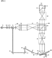
- FIG. 6 shows an optical system of a hologram pickup device of a two-beam angle multiplexing system according to the second embodiment of the present invention.
- the difference from the first embodiment is the detection optical system (from the area division wavelength plate 180 to the image pickup devices 112 and 113), and other than that is the same as the first embodiment.
- the recording method of the present embodiment is the same as that of the first embodiment. Further, since the same operation is performed except for the detection optical system at the time of reproduction, the following will be described with respect to the reproduction light transmitted through the PBS prism 28.
- FIG. 7 shows the divided wave plate 180.
- the divided wave plate 180 is a wave plate having a region A and a region B.
- the light beam transmitted through the region A is P-polarized light
- the light beam transmitted through the region B is S-polarized light.
- the region A can be realized by a wave plate having a phase difference of 1 / 2 ⁇ , an azimuth axis of 45 degrees, and the region B having a phase difference of 0 ⁇ .
- the divided wave plate is, for example, a lamination of different wave plates, a photonic crystal, a liquid crystal wave plate, or the like.
- segmentation wavelength plate of a present Example is arrange
- the reproduction light transmitted through the divided wavelength plate 180 enters the PBS 101 through the relay lens 127.
- a part of the reproduction light transmitted through the region A of the divided wavelength plate 180 is P-polarized light, it passes through the PBS 101 and enters the image sensor 112.
- a part of the reproduction light transmitted through the region B is S-polarized light, it reflects the PBS 101 and enters the image sensor 113.
- reproduction image data is generated based on the reproduction light incident on the image sensors 112 and 113.
- the galvanometer mirrors 38 and 50 rotate by a small amount, the incident angle of the reference light to the optical information recording medium 300 is changed, and the reproduction light of the next page enters the image sensors 112 and 113.
- reproduction image data is generated based on the reproduction light incident on the image sensors 112 and 113.
- the reproduction image data of the angle-multiplexed page in the optical information recording medium is generated.
- the present embodiment is the same as the first embodiment in terms of branching to a plurality of image sensors using polarized light. However, instead of switching the two image sensors for each page to be reproduced as in the first embodiment, A page is detected by two image sensors.
- the divided wavelength plate is placed on the image plane, it is possible to divide the reproduced signal without deterioration.
- the transfer time Tt in FIG. 3 is halved.
- high-speed reproduction can be realized by using a plurality of imaging elements and a branch element using polarized light (a divided wavelength plate and a polarization branch element (PBS prism)).
- the present embodiment is characterized in that the reproduction light transmitted through different regions of the divided wavelength plate has two types of polarization components that are substantially orthogonal, and the two types of polarization components are incident on different image pickup devices.
- the same effect can be obtained if the incident light of the reproduction light is divided into a plurality of image sensors. Further, the division method is not limited.
- the angle multiplexing method has been described, but the same effect can be obtained even with the shift multiplexing method, for example.
- the same effect can be obtained with other systems as long as the two-dimensional data is detected by the image sensor.
- this embodiment since this embodiment can realize high pixel and high-speed transfer, it may be applied to an imaging camera.
- the galvanometer mirror is used to change the incident angle to the optical recording medium, but the present invention is not limited to this.
- an optical axis angle variable element such as an acousto-optic element may be used.
- the divided wavelength plate 180 to the imaging elements 112 and 113 may be configured as one component or may be divided.
- the hologram optical pickup apparatus for recording / reproduction is described.
- a hologram optical pickup apparatus for reproduction may be used.
- the divided wavelength plates of the first embodiment and the present embodiment may be combined.
- the optical path of the reproduction light is selected by switching the high-speed polarization switching element 200 with respect to the reproduction light.
- the light is incident on the divided wave plate 701 or 702 having the same characteristics as in FIG.
- the reproduction light transmitted through different regions of the divided wavelength plate has two types of polarization components that are substantially orthogonal, and the two types of polarization components are different image sensors (image sensors 900 and 901 or image sensors 902 and 903). Is incident on.
- image sensors 900 and 901 or image sensors 902 and 903 are different image sensors
- FIG. 8 shows an optical system of a two-beam angle multiplexing type hologram pickup apparatus according to a third embodiment of the present invention.
- the difference from the first embodiment is that there are two galvano mirrors used for angle multiplexing, and it corresponds to recording / reproduction from two different directions.
- the light beam emitted from the light source 11 passes through the collimator lens 12 and is converted into a desired beam diameter, and then passes through the shutter 13 and enters the polarization control element 14.
- the light beam is converted into P-polarized light and S-polarized light by the polarization control element 14.
- the polarization control element 14 is an element that converts the light into predetermined polarized light according to recording or reproduction. In this embodiment, it is assumed that P-polarized light and S-polarized light are converted during recording, and S-polarized light is converted during reproduction.
- the light beam emitted from the polarization control element 14 enters the PBS prism 15, P-polarized light is transmitted, and S-polarized light is reflected.
- the light beam transmitted through the PBS prism is called signal light, and the reflected light beam is called reference light.
- the signal light transmitted through the PBS prism 15 is converted into a desired beam diameter by the beam expander 25.
- the signal light transmitted through the beam expander 25 enters the spatial light modulator 29 through the phase mask 26, the relay lens 27, and the PBS prism 28, and is added with two-dimensional data.
- the signal light to which information is added by the spatial light modulator 29 is reflected by the PBS prism 28, and is condensed in the optical information recording medium 300 through the relay lens 30, the spatial filter 31, and the objective lens 32.
- the reference light reflected from the PBS prism 15 enters the high-speed polarization control element 133.
- the high-speed polarization control element 100 converts the reference light into P-polarized light.
- the P-polarized reference light emitted from the high-speed polarization control element 100 passes through the PBS prism 134 and enters the half-wave plate 35.
- the reference light emitted from the half-wave plate 35 is converted into S-polarized light.
- the reference light emitted from the half-wave plate 35 enters the optical information recording medium 300 through the mirrors 36 and 37, the galvanometer mirror 38, and the scanner lens 39.
- an interference fringe pattern is formed in the optical information recording medium 300.
- the interference fringe pattern is recorded as a hologram in the recording medium (Recording 1).
- the shutter 13 is closed and the information to be recorded next is displayed by the spatial light modulator 29. Then, the high-speed polarization control element 133 is switched, and the reference light is converted into S-polarized light. Thereafter, the shutter 13 is opened, and the S-polarized reference light emitted from the high-speed polarization control element 133 is incident on the optical information recording medium 300 through the PBS prism 134, the mirrors 135, 136, 137, the galvanometer mirror 138, and the scanner lens 139. At this time, when the signal light and the reference light are incident on the optical information recording medium 300 so as to overlap each other, an interference fringe pattern is formed in the optical information recording medium 300.
- This interference fringe pattern is recorded as a hologram in the recording medium (Recording 2). Further, during the recording 2, the galvano mirror 38 is rotated by a minute angle, and the incident angle of the reference light to the optical information recording medium 300 is changed. By repeating such recording 1 and recording 2, angle multiplex recording is continuously performed.
- the light beam emitted from the light source 11 passes through the collimator lens 12 and is converted into a desired beam diameter, and then passes through the shutter 13 and enters the polarization control element 14.
- the light beam is converted into S-polarized light by the polarization control element 14.
- the light beam transmitted through the polarization control element 14 reflects the PBS prism 15.
- the light beam reflected from the PBS prism 15 is referred to as reference light.
- the high-speed polarization control element 133 converts the reference light into P-polarized light.
- the P-polarized reference light emitted from the high-speed polarization control element 133 passes through the PBS prism 134 and enters the half-wave plate 35.
- the reference light emitted from the half-wave plate 35 is converted into S-polarized light.
- the reference light emitted from the half-wave plate 35 enters the galvanometer mirror 50 through the mirrors 36 and 37, the galvanometer mirror 38, the scanner lens 39, the optical information recording medium 300, and the quarter-wave plate 51.
- the galvanometer mirror 50 is controlled so that the incident reference light is substantially perpendicular to the galvanometer mirror 50.
- the incident reference light is reflected in a substantially opposite direction, and reenters the optical information recording medium 300 through the quarter-wave plate 51.
- reproduction light defracted light of the reference light
- predetermined information is generated in the direction of the objective lens 32 from the recording area.
- the reproduction light enters the high-speed polarization control element 100 through the objective lens 32, the relay lens 30, the spatial filter 31, and the PBS prism 28.
- the high-speed polarization control element 100 emits P-polarized reproduction light.
- the reproduction light emitted from the high-speed polarization control element 100 passes through the PBS prism 101 and enters the image sensor 102. Then, reproduction image data is generated based on the reproduction light incident on the image sensor 102 (reproduction 1).
- the high-speed polarization control elements 100 and 133 are switched so that the outgoing polarized light becomes S-polarized light.
- the S-polarized reference light emitted from the high-speed polarization control element 133 passes through the PBS prism 134, mirrors 135, 136, and 137, the galvano mirror 138, the scanner lens 139, the optical information recording medium 300, and the quarter wavelength plate 151, and then the galvano. Incident on the mirror 150.
- the galvanometer mirror 150 is controlled so that the incident reference light is substantially perpendicular to the galvanometer mirror 150. For this reason, the incident reference light is reflected substantially in the opposite direction, and reenters the optical information recording medium 300 via the quarter-wave plate 151.
- reproduction light (diffracted light of the reference light) having predetermined information is generated in the direction of the objective lens 32 from the recording area.
- the reproduction light enters the high-speed polarization control element 100 through the objective lens 32, the relay lens 30, the spatial filter 31, and the PBS prism 28.
- the high-speed polarization control element 100 converts the reproduction light into S-polarized light. Therefore, the reproduction light is reflected by the PBS prism 101 and enters the image sensor 103. Then, reproduction image data is generated based on the reproduction light incident on the image sensor 103 (reproduction 2).
- the image pickup device of the present embodiment will be described using a single buffer system in which one buffer is mounted, but the same effect can be obtained even in a multi-buffer system in which two or more buffers are mounted.
- FIG. 9 shows an image sensor and a timing chart in a hologram system with one image sensor. Note that the description will be given with the reproduction of five pages, but the actual number of multiplexing is not limited to this.
- the galvanometer mirror has the same transfer speed as that of one hologram system (Example 1).
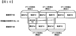
- FIG. 10 shows a timing chart of the image sensor and the high-speed polarization control elements 100 and 133 in the hologram system of this embodiment. Note that the galvanometer mirror does not contribute to the frame rate because the galvanometer mirrors 138 and 150 for the reproduction 2 are rotated during the reproduction 1, for example.
- the image pickup device shown in FIG. 9 is a single hologram system
- exposure could not be performed while the reproduction signal was being transferred.
- another image sensor can perform exposure while one image sensor transfers a reproduction signal. For this reason, it is possible to improve the frame rate as compared with the case where detection is performed by one image sensor.
- high-speed reproduction can be realized by using a plurality of imaging elements and a branch element using polarization (polarization control element and polarization branch element (PBS prism)).
- PBS prism polarization control element and polarization branch element
- the present embodiment is characterized in that the polarization is selectively switched in accordance with the information to be reproduced, and one image sensor on which the reproduction light is incident is switched in accordance with the switching.
- two image sensors are used, but a plurality of image sensors may be used.
- a plurality of image sensors may be used. For example, when four image sensors are used, the configuration shown in FIG. By doing so, it is possible to further increase the speed.
- the angle multiplexing method has been described, but the same effect can be obtained even with the shift multiplexing method, for example.
- the same effect can be obtained with other systems as long as the two-dimensional data is detected by the image sensor.
- the present invention since high pixels and high-speed transfer can be realized by using this embodiment, the present invention may be applied to an imaging camera or the like.
- the galvanometer mirror is used to change the incident angle to the optical recording medium, but the present invention is not limited to this.
- an optical axis angle variable element such as an acousto-optic element may be used.
- the high-speed polarization control element 100 to the imaging elements 112 and 113 may be configured as one component or may be divided.
- the hologram optical pickup apparatus for recording / reproduction is described.
- a hologram optical pickup apparatus for reproduction may be used.
- FIG. 11 shows the overall configuration of an optical information recording / reproducing apparatus that reproduces or records / reproduces digital information using a hologram.
- the optical information recording / reproducing apparatus includes, for example, a hologram optical pickup apparatus 60 configured as shown in FIG. 1, a phase conjugate optical system 512, an optical information recording medium Cure optical system 513, an optical information recording medium position detection optical system 514, and an optical information recording.
- a medium driving element 70 is provided, and the optical information recording medium 300 is configured such that the recording position relative to the optical pickup device can be changed.
- the optical pickup device 60 plays a role of emitting reference light and signal light to the optical information recording medium 300 and recording digital information using a hologram.
- the information signal to be recorded is sent by the controller 89 to the spatial light modulator in the optical pickup device 60 via the signal generation circuit 86, and the signal light is modulated by the spatial light modulator.
- the phase conjugate light of the reference light emitted from the optical pickup device 60 is generated by the phase conjugate optical system 512.
- the phase conjugate optical system 512 indicates, for example, the galvanometer mirror 50 in the case of FIG.
- the phase conjugate light is a light wave that travels in the opposite direction while maintaining the same wavefront as the input light.
- the reproduction light reproduced by the phase conjugate light is detected by a plurality of image sensors in the optical pickup device 60, and the signal is reproduced by the signal processing circuit 85.
- the irradiation time of the reference light and the signal light applied to the optical information recording medium 300 can be adjusted by controlling a shutter opening / closing time described later in the optical pickup device 60 through the shutter control circuit 87 by the controller 89.
- the optical information recording medium Cure optical system 513 plays a role of generating a light beam used for pre-cure and post-cure of the optical information recording medium 300.
- the pre-cure is a pre-process in which, when information is recorded at a desired position in the optical information recording medium 300, a predetermined light beam is irradiated in advance before the reference light and signal light are irradiated to the desired position.
- Post-cure is a post-process for irradiating a predetermined light beam after recording information at a desired position in the optical information recording medium 300 so that additional recording cannot be performed at the desired position.
- the optical information recording medium position detection optical system 514 is used to detect the position of the optical information recording medium 300.
- a signal corresponding to the position is detected by the optical information recording medium position detection optical system 514, and the controller 89 uses the detected signal to pass the position control circuit 88.
- the position of the optical information recording medium 300 can be controlled.
- a predetermined light source driving current is supplied from the light source driving circuit 82 to the light sources in the optical pickup device 60, the optical information recording medium Cure optical system 513, and the optical information recording medium position detecting optical system 514. Can emit a light beam.
- the recording technology using holography is a technology capable of recording ultra-high density information, for example, an allowable error with respect to the tilt of the optical information recording medium 300 tends to be extremely small. Therefore, a signal for detecting the angle error signal is output in the optical pickup device 60 of the present embodiment. Using this signal, the servo signal generation circuit 83 generates an angle error signal for servo control, and an angle control element such as a galvanometer mirror is provided to correct the deviation amount via the servo control circuit 84. Further, the hologram optical pickup device 60, the phase conjugate optical system 512, the optical information recording medium Cure optical system 513, and the optical information recording medium position detection optical system 514 combine several optical system configurations or all optical system configurations into one. It may be simplified. In FIGS. 1 and 6 of the first, second, and third embodiments, the hologram optical pickup device 60 and the phase conjugate optical system 512 are shown together.
- the recording / reproducing hologram apparatus has been described.
- the signal generating circuit 86, the shutter 87, the optical information recording medium Cure optical system 513, and the like may be deleted to form a reproducing hologram apparatus.
- the hologram apparatus performs not only high-speed reproduction using information captured by a plurality of image sensors in the optical pickup device 60 according to the first and third embodiments, but also controls the following image sensors. May be.
- the reproduction performance of information captured by a predetermined image sensor when the reproduction performance of information captured by a predetermined image sensor is poor, the same information may be reproduced by different image sensors. By doing so, for example, it is possible to improve the deterioration of the reproduction signal due to a defect of a predetermined image sensor, a positional shift in the optical path to the image sensor, an aberration, or the like. Also, if the reproduction performance of a given image sensor is significantly degraded, the high-speed polarization variable element is controlled so that the reproduction light does not enter the image sensor, and reproduction is performed using only the image sensor that can obtain the reproduction performance. good. Thereby, more stable reproduction can be performed with respect to the hologram system with one image sensor.
- this embodiment can be expressed as follows. That is, an optical pickup device that reproduces first page data and second page data from an optical information recording medium in which an interference pattern of signal light and reference light is recorded as a hologram, and a laser that emits reference light
- a detection optical system comprising: an emission unit; a lens that makes the reference light emitted from the laser emission unit enter the optical information recording medium; and a detection optical unit that detects reproduction light diffracted from the optical information recording medium based on the reference light.
- the unit includes a first image sensor and a second image sensor. After obtaining the first page data by the first image sensor, the second image data is obtained by the second image sensor. To do.
- the third image data is obtained by the first image sensor.
- the fourth image data is acquired by the second image sensor, and high-speed data processing can be performed by properly using the first image sensor and the second image sensor.
- this invention is not limited to the above-mentioned Example, Various modifications are included.
- the above-described embodiments have been described in detail for easy understanding of the present invention, and are not necessarily limited to those having all the configurations described.
- a part of the configuration of one embodiment can be replaced with the configuration of another embodiment, and the configuration of another embodiment can be added to the configuration of one embodiment.
Landscapes
- Physics & Mathematics (AREA)
- Optics & Photonics (AREA)
- Holo Graphy (AREA)
- Optical Recording Or Reproduction (AREA)
Abstract
高速再生を実現可能なホログラム光ピックアップ装置、ホログラム装置、高速撮像装置を提供することを目的とする。 信号光と参照光の干渉パターンがホログラムとして記録されている記録媒体から情報を再生する光ピックアップ装置であって、参照光を出射するレーザ出射部と、レーザ出射部から出射された前記参照光を光情報記録媒体に入射するレンズと、前記参照光に基づいて前記光情報記録媒体から回折した再生光を検出する検出光学部とを備え、前記検出光学部には、複数の撮像素子が含まれていることを特徴とする光ピックアップ装置を用いる。
Description
本発明は、ホログラム光ピックアップ装置、ホログラム装置、高速撮像装置などに関する。
現在、青紫色半導体レーザを用いた、Blu-ray Disc規格により、民生用においても50GB程度の記録密度を持つ光ディスクの商品化が可能となってきた。今後は、光ディスクでも100GB~1TBというHDD(Hard Disk Drive)容量と同程度まで大容量化が望まれる。
しかしながら、このような超高密度を光ディスクで実現するためには、短波長化と対物レンズ高NA化による高密度化技術とは異なる新しい方式による高密度化技術が必要である。
次世代のストレージ技術に関する研究が行われる中、ホログラフィを利用してデジタル情報を記録するホログラム記録技術が注目を集めている。
ホログラム記録技術とは、空間光変調器により2次元的に変調されたページデータの情報を有する信号光を、記録媒体の内部で参照光と重ね合わせ、その時に生じる干渉縞パターンによって記録媒体内に屈折率変調を生じさせることで情報を記録媒体に記録する技術である。
情報の再生時には、記録時に用いた参照光を記録媒体に照射すると、記録媒体中に記録されているホログラムが回折格子のように作用して回折光を生じる。この回折光が記録した信号光と位相情報を含めて同一の光として再生される。
再生された信号光は、CMOSやCCDなどの撮像素子を用いて2次元的に検出される。このようにホログラム記録技術は、1つのホログラムによって2次元的な情報を一気に光記録媒体に記録し、さらにこの情報を再生することを可能とするものであり、そして、記録媒体のある場所に複数のページデータを重ね書きすることができるため、大容量かつ高速な情報の記録再生を果たすことができる。
ホログラム記録技術として、例えば特開2004-272268号公報(特許文献1)がある。特許文献1には課題として「ホログラフィック媒体の達成可能な密度/ 容量を増大させること。」と記載があり、解決手段として「ホログラムの隣接するスタック間で部分的空間的重なり合いによってホログラムが空間的に多重化される、多重化方法および装置が開示される。各々のスタックは、例えば角度、波長、位相符号、ペリストロピック、またはフラクタル多重化等の別の多重化技術の完全な利点をさらに取り得る。ホログラムを書き込む信号光のビームウエストに等しい量が、ホログラムの個々のスタックを分離する。再現時に、あるホログラムとそのホログラムに隣接するホログラムとは、全て同時に読み出される。再現されたデータのビームウエストにフィルタが配置されることにより、読み出された隣接するホログラムは、カメラ面まで伝達されない。もしくは、これらの所望ではない再現は、制限された角度パスバンドを有する光学系においては、中間面の角度フィルタによってフィルタリングされ得る。」と記載されている。
また、他の背景技術としては特開2005-233998号公報がある。本公報には「1本の再生用参照光の照射により、同時に複数の回折光を異なる方向に発生させて、これを同時に複数の撮像素子で受光して記録を再生させる。」と記載がある。また、他の背景技術としてはWO2012-053198号公報がある。本公報には「第2の参照光は複数に分岐して各々に異なる位相変化を与え、干渉した光を複数のCCDで検出することで再生する」と記載がある。
特許文献1は、上記したようにホログラフィック媒体の達成可能な密度/容量を増大させている。その一方でホログラムシステムでは再生の高速化が課題となっている。再生速度は撮像素子の画素数とフレームレートに依存しており、高画素のページデータを用いるホログラムシステムにとって、再生の高速化が困難となっている。また、特許文献2,3では、単に撮像装置の受光面が複数あるのみで、多数ページの高速再生には課題がある。
そこで、本発明では、高速再生を実現可能なホログラム光ピックアップ装置、ホログラム装置、高速撮像装置を提供することを目的とする。
上記目的は、特許請求の範囲に記載の発明によって達成できる。一例を挙げるならば、信号光と参照光の干渉パターンがホログラムとして記録されている記録媒体から情報を再生する光ピックアップ装置であって、参照光を出射するレーザ出射部と、レーザ出射部から出射された前記参照光を光情報記録媒体に入射するレンズと、前記参照光に基づいて前記光情報記録媒体から回折した再生光を検出する検出光学部とを備え、前記検出光学部には、複数の撮像素子が含まれていることを特徴とする光ピックアップ装置を用いることにより上記目的を達成できる。
高速再生を実現可能なホログラム光ピックアップ装置、ホログラム装置、高速撮像装置を提供することができる。
以下、各実施例を説明する。
図1は本発明の第1の実施例に係る2光束角度多重方式のホログラムピックアップ装置の光学系を示したものである。
まず、本実施例の記録方法について説明する。光源11を出射した光ビームはコリメートレンズ12を透過し、所望のビーム径に変換された後、シャッタ13を経て、偏光制御素子14に入射する。そして、光ビームは偏光制御素子14によってP偏光とS偏光に変換される。偏光制御素子14は記録または再生に応じて出射偏光を所定の偏光に変換する素子である。本実施例では記録時にP偏光とS偏光、再生時にS偏光に変換するとする。
偏光制御素子14を出射した光ビームはPBSプリズム15に入射し、P偏光は透過し、S偏光は反射する。ここで、PBSプリズムを透過した光ビームを信号光、反射した光ビームを参照光と呼ぶ。PBSプリズム15を透過した信号光は、ビームエキスパンダ25によって所望のビーム径に変換される。ビームエキスパンダ25を透過した信号光は、位相マスク26、リレーレンズ27、PBSプリズム28を経て空間光変調器29に入射し、2次元データが付加される。空間光変調器29は信号光に2次元データを付加する光学素子である。
空間光変調器29によって情報を付加された信号光は、PBSプリズム28を反射し、リレーレンズ30、空間フィルタ31、対物レンズ32を経て、光情報記録媒体300内に集光する。
一方、PBSプリズム15を反射した参照光は、ミラー36、37を反射し、ガルバノミラー38に入射する。ガルバノミラー38はミラーの角度を制御可能な素子である。このガルバノミラー38を用いることで参照光の光情報記録媒体への入射角度を変えることができるため、角度多重を実現することができる。ガルバノミラー38を反射した参照光はスキャナーレンズ39を経て光情報記録媒体300に入射する。このとき、光情報記録媒体300内に信号光と参照光が互いに重ね合うように入射されることで、光情報記録媒体300内には干渉縞パターンが形成される。そして、この干渉縞パターンが記録媒体内にホログラムとして記録される。本実施例では、2次元データが記録されたホログラムのことをページと呼び、ページが多重化されている領域のことをブックと呼ぶ。
光情報記録媒体300に情報が記録された後、シャッタ13が閉じ、次に記録される情報が空間光変調器29によって表示される。同時に、ガルバノミラー38が微小角度回転して、光情報記録媒体300への参照光の入射角度が変更される。その後、シャッタ13が開くと次に記録される情報が光情報記録媒体300の同一ブックに前に記録した角度と異なる角度で記録される。これを繰り返すことで角度多重記録を行なう。
次に本実施例の再生方法について図1を用いて説明する。光源11を出射した光ビームはコリメートレンズ12を透過し、所望のビーム径に変換された後、シャッタ13を通り、偏光制御素子14に入射する。そして、光ビームは偏光制御素子14によってS偏光に変換され、PBSプリズム15を反射する。以下、PBSプリズム15を反射した光ビームを参照光と呼ぶ。
PBSプリズム15を反射した参照光は、ミラー36、37を反射し、ガルバノミラー38に入射する。ガルバノミラー38を反射した参照光はスキャナーレンズ39、光情報記録媒体300、1/4波長板51を経て、ガルバノミラー50に入射する。ガルバノミラー50は入射した参照光がガルバノミラー50に対して略垂直となるように制御されている。このため、入射した参照光は略反対方向に反射され、1/4波長板51を経て、光情報記録媒体300に再入射する。そして参照光が再び光情報記録媒体300に入射することで、記録領域から所定の情報を有した再生光(参照光の回折光)が対物レンズ32の方向に発生する。
そして再生光は、対物レンズ32、リレーレンズ30、空間フィルタ31、PBSプリズム28を経て、高速偏光制御素子100に入射する。本実施例の高速偏光制御素子100は、強誘電体液晶などの液晶素子であり、高速に出射偏光をP偏光とS偏光に変換することが可能な素子である。
高速偏光制御素子100を出射した再生光は、PBSプリズム101を経て撮像素子102または撮像素子103に入射する。そして撮像素子102または撮像素子103に入射した再生光に基づいて、再生画像データが生成される。次にガルバノミラー38、50が微小量回転して、光情報記録媒体300への参照光の入射角度が変更され、次のページの再生光が撮像素子103または撮像素子102に入射する。そして撮像素子103または撮像素子102に入射した再生光に基づいて、再生画像データが生成される。これにより、光情報記録媒体内の角度多重されたページの再生画像データが生成される。
図2は、本実施例の撮像素子102、103の検出方法を説明する図である。ここでは、図2Aは奇数ページを再生する場合、図2Bは偶数ページを再生する場合を示している。
奇数ページを再生する場合、高速偏光制御素子100はP偏光を出射する。このため、高速偏光制御素子100を出射した再生光は、PBSプリズム101を透過し、撮像素子101に入射する(図2A)。そして偶数ページを再生する場合、高速偏光制御素子100はS偏光を出射する。このため、高速偏光制御素子100を出射した再生光は、PBSプリズム101を反射し、撮像素子102に入射する。このように本実施例は、複数の撮像素子を切替えることを特徴としている。
ここで、本実施例の効果について説明する。本実施例の撮像素子は、簡単のため1つのバッファを搭載するシングルバッファ方式で説明する。ただし、2つ以上のバッファを搭載するマルチバッファ方式であっても同様の効果が得られる。
まず、1つの撮像素子を用いた従来のホログラムシステムについて説明する。図3は、1つの撮像素子を用いた従来のホログラムシステムにおける撮像素子とガルバノミラー38、50のタイミングチャートを示したものである。なお、説明は5ページ分の再生で行なうが、実際の多重数はこれに限定されない。
1つの撮像素子を用いた従来のホログラムシステムの場合、図3に示すように撮像素子は露光と転送から構成される。再生時には所定時間Teだけ露光した後、得られた再生信号を時間Ttで信号処理回路(図示せず)に転送する。このとき、再生信号を転送している間は、露光することができない。また、再生信号を転送している間に、光情報記録媒体300への参照光入射角度が次のページに合うようガルバノミラー38、50が時間Trかけて回転する。
ホログラムでは、記録速度/容量の観点から1ページの記録容量を大容量化する必要がある。撮像素子の転送時間は、画素数に依存しており、高画素な程、転送時間は長くなってしまう。このため、1ページの記録容量を大容量(高画素)化すると転送時間が長くなってしまう。実際のホログラムシステムでは露光時間やガルバノミラー回転時間に対して転送時間が長くなってしまう。
次に、2つの撮像素子を用いた本実施例のホログラムシステムについて説明する。図4は本実施例のホログラムシステムにおける撮像素子とガルバノミラー38、50のタイミングチャートを示したものである。
1ページ目の再生に関しては図3に示す従来のホログラムシステムと同様である。ただし、本実施例の場合には撮像素子102の露光が終わった時点でガルバノミラー38、50が回転するとともに高速偏光切替素子100の出射偏光を切替える。これにより、次のページ(2ページ目)の再生光が撮像素子103に入射する。そして、撮像素子103の露光を行う。この間、撮像素子102では再生信号の転送が行われている。そして、撮像素子103の露光が終わった時点でガルバノミラー38、50を回転するとともに高速偏光切替素子100の出射偏光を切替える。これにより、次のページ(3ページ目)の再生光が撮像素子102に入射する。これを繰返すことで、連続再生が可能となる。
図3に示す従来のホログラムシステムの場合には、再生信号を転送している間は露光できなかった。それに対し、発明のホログラムシステムの場合には、1つの撮像素子が再生信号を転送している間は、もう1つの撮像素子が露光をすることができる。このため、従来に対して、フレームレートを向上することが可能となる。
ここで、上記したように本実施例は転送時間が長い場合において大きな効果があることがわかる。例えば、マルチバッファ方式のように実効的な転送時間が短くなった場合、本実施例の効果が小さくなってしまう。しかし、以下のようにすることで本実施例の効果を向上することが可能となる。
撮像素子の転素時間は、画素数に依存しており、高画素な程、転送時間は長くなってしまう。このため、1ページの記録容量を大容量(高画素)化すると転送時間が長くなってしまう。また、再生速度は、1ページ当たりの記録容量とフレームレートの積となる。
従来のホログラムシステムの場合には、1ページ当たりの記録容量を増やすと、撮像素子のフレームレートが低下してしまい、積である再生速度は大きく変えられなかった。それに対し、本実施例の場合には、1ページ当たりの記録容量を増やしても、撮像素子単品のフレームレートの低下分を複数の撮像素子を用いることで補償している。つまり従来のホログラムシステムに対し、再生速度を向上することが可能となる。
以上のように、本実施例は複数の撮像素子および偏光を用いた分岐素子(偏光制御素子と偏光分岐素子(PBSプリズム))を用いることで高速再生が実現可能となる。また、本実施例は、再生する情報に応じて偏光を選択的に切替え、その切替えに応じて再生光が入射する撮像素子が切替ることを特徴としている。
なお、本実施例では2つの撮像素子を用いたが、複数の撮像素子を用いても良い。例えば、4つの撮像素子を用いる場合には、図5のような構成とすれば良い。このようにすることで、さらなる高速化が可能となる
そして本実施例では、角度多重方式で説明を行ったが、例えばシフト多重方式であっても同様の効果を得られる。また他の方式であっても2次元データを撮像素子で検出する構成であれば同様の効果が得られる。さらに、本実施例を用いることで高画素、高速転送を実現できるため撮像用のカメラ等に適用しても良い。
そして本実施例では、角度多重方式で説明を行ったが、例えばシフト多重方式であっても同様の効果を得られる。また他の方式であっても2次元データを撮像素子で検出する構成であれば同様の効果が得られる。さらに、本実施例を用いることで高画素、高速転送を実現できるため撮像用のカメラ等に適用しても良い。
本実施例では、光記録媒体への入射角度を変えるためにガルバノミラーを用いたがこれには限定されず、例えば音響光学素子などの光軸角度可変素子を用いても良い。また、本実施例では、奇数ページと偶数ページの再生で撮像素子を切替えたが切替え方法は限定されない。さらに、高速偏光制御素子100から撮像素子102、103までを一つの部品として構成しても良いし、分割しても良い。
そして本実施例では、記録再生用のホログラム光ピックアップ装置で説明したが、再生用のホログラム光ピックアップ装置でも良い
図6は本発明の第2の実施例に係る2光束角度多重方式のホログラムピックアップ装置の光学系を示したものである。実施例1との違いは、検出光学系(領域分割波長板180から撮像素子112、113)であり、それ以外は実施例1と同様である。このため、本実施例の記録方法は実施例1と同様である。また、再生時も検出光学系以外は同様であるので、PBSプリズム28を透過した再生光について以下を説明を行う。
PBSプリズム28を透過した再生光は分割波長板180に入射する。図7に分割波長板180を示す。分割波長板180は領域Aと領域Bを有している波長板である。領域Aを透過した光ビームがP偏光、領域Bを透過した光ビームがS偏光となっている。例えば、本実施例の場合、分割波長板180に入射する偏光がP偏光であるので領域Aは位相差1/2λ、方位軸45度、領域Bは位相差0λの波長板で実現できる。分割波長板は、例えば異なる波長板の張り合わせ、フォトニック結晶、液晶波長板等である。なお、本実施例の分割波長板は従来のホログラムシステムにおいて撮像素子を配置する像面に相当する位置に配置していることを特徴としている。
分割波長板180を透過した再生光は、リレーレンズ127を経てPBS101に入射する。ここで、分割波長板180の領域Aを透過した再生光の一部はP偏光なのでPBS101を透過し、撮像素子112に入射する。また、領域Bを透過した再生光の一部はS偏光なのでPBS101を反射し、撮像素子113に入射する。そして撮像素子112、113に入射した再生光に基づいて、再生画像データが生成される。次にガルバノミラー38、50が微小量回転して、光情報記録媒体300への参照光の入射角度が変更され、次のページの再生光が撮像素子112、113に入射する。そして撮像素子112、113に入射した再生光に基づいて、再生画像データが生成される。これにより、光情報記録媒体内の角度多重されたページの再生画像データが生成される。
以下、本実施例の効果について説明する。本実施例は、偏光を用いて複数の撮像素子に分岐する観点では実施例1と同様であるが、実施例1のように2つの撮像素子を再生するページごとに切替えるのではなく、全てのページを2つの撮像素子で検出している。ここで、本実施例では分割波長板を像面に置いたため、再生信号の劣化なく分割すること可能となっている。
そして、本実施例では1つのページを2つに分割しているので撮像素子の画素数が少なくて良いため、撮像素子単品の転送時間を短くすることが可能となる。また、実施例1に対して、高速偏光制御素子を駆動しないので、複雑な制御をする必要がなくなり、制御の簡素化が実現できる。本実施例におけるタイミングチャートとしては、図3における転送時間Ttが半分となる。
以上のように、本実施例は複数の撮像素子および偏光を用いた分岐素子(分割波長板と偏光分岐素子(PBSプリズム))を用いることで高速再生が実現可能となる。また、本実施例は、分割波長板の異なる領域を透過した再生光は略直交する2種類の偏光成分となっており、2種類の偏光成分は異なる撮像素子に入射することを特徴としている。
なお、本実施例では2つの撮像素子を用いたが、複数の撮像素子に対して再生光の入射光を分割する構成であれば同様の効果が得られる。また、分割方法は限定されない。
本実施例では、角度多重方式で説明を行ったが、例えばシフト多重方式であっても同様の効果を得られる。また他の方式であっても2次元データを撮像素子で検出する構成であれば同様の効果が得られる。さらに、本実施例を用いることで高画素、高速転送を実現できるため撮像用のカメラに適用しても良い。
本実施例では、光記録媒体への入射角度を変えるためにガルバノミラーを用いたがこれには限定されず、例えば音響光学素子などの光軸角度可変素子を用いても良い。さらに、分割波長板180から撮像素子112、113までを一つの部品として構成しても良いし、分割しても良い。
そして本実施例では、記録再生用のホログラム光ピックアップ装置で説明したが、再生用のホログラム光ピックアップ装置でも良い。
また、図12のように実施例1と本実施例の分割波長板を組み合わせても良い。この場合、まず再生光に対して、高速偏光切替素子200を切り替えることで、再生光の光路を選択する。そして、図7と同様の特性を有する分割波長板701または702に入射する。このとき、分割波長板の異なる領域を透過した再生光は略直交する2種類の偏光成分となっており、2種類の偏光成分は異なる撮像素子(撮像素子900、901または撮像素子902、903)に入射する。このような構成とすることで、実施例1の図5に対し、制御部品が少なくなる利点がある。また、コストの観点からも有利となる。本実施例におけるタイミングチャートとしては、図4における転送時間Ttが半分となる。
図8は本発明の第3の実施例に係る2光束角度多重方式のホログラムピックアップ装置の光学系を示したものである。実施例1との違いは、角度多重に用いるガルバノミラーが2つとなり、異なる2方向からの記録再生に対応した点である。
まず、本実施例の記録方法について説明する。光源11を出射した光ビームはコリメートレンズ12を透過し、所望のビーム径に変換された後、シャッタ13を通り、偏光制御素子14に入射する。そして、光ビームは偏光制御素子14によってP偏光とS偏光に変換される。偏光制御素子14は記録または再生に応じて所定の偏光に変換する素子である。本実施例では記録時にP偏光とS偏光、再生時にS偏光に変換するとする。
偏光制御素子14を出射した光ビームはPBSプリズム15に入射し、P偏光は透過し、S偏光は反射する。ここで、PBSプリズムを透過した光ビームを信号光、反射した光ビームを参照光と呼ぶ。PBSプリズム15を透過した信号光は、ビームエキスパンダ25によって所望のビーム径に変換される。ビームエキスパンダ25を透過した信号光は、位相マスク26、リレーレンズ27、PBSプリズム28を経て空間光変調器29に入射し、2次元データが付加される。
空間光変調器29によって情報を付加された信号光は、PBSプリズム28を反射し、リレーレンズ30、空間フィルタ31、対物レンズ32を経て、光情報記録媒体300内に集光する。
一方、PBSプリズム15を反射した参照光は、高速偏光制御素子133に入射する。所定ページを記録する際、高速偏光制御素子100は参照光をP偏光に変換する。高速偏光制御素子100を出射したP偏光の参照光はPBSプリズム134を透過し、1/2波長板35に入射する。1/2波長板35を出射した参照光はS偏光に変換される。そして、1/2波長板35を出射した参照光は、ミラー36、37、ガルバノミラー38、スキャナーレンズ39を経て光情報記録媒体300に入射する。このとき、光情報記録媒体300内に信号光と参照光が互いに重ね合うように入射されることで、光情報記録媒体300内には干渉縞パターンが形成される。そして、この干渉縞パターンが記録媒体内にホログラムとして記録される(記録1)。
記録1によって光情報記録媒体300に情報が記録された後、シャッタ13が閉じ、次に記録される情報が空間光変調器29によって表示される。そして、高速偏光制御素子133が切替わり、参照光がS偏光に変換される。その後、シャッタ13が開き、高速偏光制御素子133を出射したS偏光の参照光はPBSプリズム134、ミラー135、136、137、ガルバノミラー138、スキャナーレンズ139を経て光情報記録媒体300に入射する。このとき、光情報記録媒体300内に信号光と参照光が互いに重ね合うように入射されることで、光情報記録媒体300内には干渉縞パターンが形成される。そして、この干渉縞パターンが記録媒体内にホログラムとして記録される(記録2)。また、記録2を行っている最中にガルバノミラー38が微小角度だけ回転して、光情報記録媒体300への参照光の入射角度が変更される。このような記録1、記録2を繰り返すことで連続的に角度多重記録を行なう。
次に本実施例の再生方法について図8を用いて説明する。光源11を出射した光ビームはコリメートレンズ12を透過し、所望のビーム径に変換された後、シャッタ13を通り、偏光制御素子14に入射する。そして、光ビームは偏光制御素子14によってS偏光に変換される。そして、偏光制御素子14を透過した光ビームは、PBSプリズム15を反射する。以下、PBSプリズム15を反射した光ビームを参照光と呼ぶ。
所定ページを再生する際、高速偏光制御素子133は参照光をP偏光に変換する。高速偏光制御素子133を出射したP偏光の参照光はPBSプリズム134を透過し、1/2波長板35に入射する。1/2波長板35を出射した参照光はS偏光に変換される。そして、1/2波長板35を出射した参照光は、ミラー36、37、ガルバノミラー38、スキャナーレンズ39、光情報記録媒体300、1/4波長板51を経て、ガルバノミラー50に入射する。ガルバノミラー50は入射した参照光がガルバノミラー50に対して略垂直となるように制御されている。このため、入射した参照光は略反対方向に反射され、1/4波長板51を経て、光情報記録媒体300に再入射する。そして参照光が再び光情報記録媒体300に入射することで、記録領域から所定の情報を有した再生光(参照光の回折光)が対物レンズ32の方向に発生する。
そして再生光は、対物レンズ32、リレーレンズ30、空間フィルタ31、PBSプリズム28を経て、高速偏光制御素子100に入射する。ここで、所定ページを再生する際、高速偏光制御素子100はP偏光の再生光を出射する。
高速偏光制御素子100を出射した再生光は、PBSプリズム101を透過し、撮像素子102に入射する。そして撮像素子102に入射した再生光に基づいて、再生画像データが生成される(再生1)。
次に、出射偏光がS偏光となるよう高速偏光制御素子100、133が切替わる。高速偏光制御素子133を出射したS偏光の参照光はPBSプリズム134、ミラー135、136、137、ガルバノミラー138、スキャナーレンズ139を経て光情報記録媒体300、1/4波長板151を経て、ガルバノミラー150に入射する。ガルバノミラー150は入射した参照光がガルバノミラー150に対して略垂直となるように制御されている。このため、入射した参照光は略反対方向に反射され、1/4波長板151を経て、光情報記録媒体300に再入射する。そして参照光が再び光情報記録媒体300に入射することで、記録領域から所定の情報を有した再生光(参照光の回折光)が対物レンズ32の方向に発生する。
そして再生光は、対物レンズ32、リレーレンズ30、空間フィルタ31、PBSプリズム28を経て、高速偏光制御素子100に入射する。ここで、高速偏光制御素子100は再生光をS偏光に変換する。このため、再生光はPBSプリズム101を反射し、撮像素子103に入射する。そして撮像素子103に入射した再生光に基づいて、再生画像データが生成される(再生2)。
ここで、本実施例の効果について説明する。本実施例の撮像素子は、簡単のため1つのバッファを搭載するシングルバッファ方式で説明するが、2つ以上のバッファを搭載するマルチバッファ方式であっても同様の効果が得られる。
図9は、撮像素子が1つのホログラムシステムにおける撮像素子とタイミングチャートを示している。なお、説明は5ページ分の再生で行なうが、実際の多重数はこれに限定されない。
撮像素子が1つの場合、実施例1同様に転送が終了するまで次の露光ができない。結果として、ガルバノミラーが1つのホログラムシステム(実施例1)と同様の転送速度となってしまう。
次に、2つの撮像素子を用いた本実施例のホログラムシステムについて説明する。図10は本実施例のホログラムシステムにおける撮像素子と高速偏光制御素子100、133のタイミングチャートを示したものである。なお、ガルバノミラーに関しては、例えば再生1を行っているときに再生2のためのガルバノミラー138、150を回転しているため、フレームレートには寄与しない。
図9に示す撮像素子が1つのホログラムシステムの場合には、再生信号を転送している間は露光できなかった。それに対し、発明のホログラムシステムの場合には、1つの撮像素子が再生信号を転送している間は、もう1つの撮像素子が露光をすることができる。このため、1つの撮像素子で検出する場合に対して、フレームレートを向上することが可能となる。
以上のように、本実施例は複数の撮像素子および偏光を用いた分岐素子(偏光制御素子と偏光分岐素子(PBSプリズム))を用いることで高速再生が実現可能となる。また、本実施例は、再生する情報に応じて偏光を選択的に切替え、その切替えに応じて再生光が入射する1つの撮像素子が切替ることを特徴としている。
なお、本実施例では2つの撮像素子を用いたが、複数の撮像素子を用いても良い。例えば、4つの撮像素子を用いる場合には、図5のような構成とすれば良い。このようにすることで、さらなる高速化が可能となる。
本実施例では、角度多重方式で説明を行ったが、例えばシフト多重方式であっても同様の効果を得られる。また他の方式であっても2次元データを撮像素子で検出する構成であれば同様の効果が得られる。さらに、本実施例を用いることで高画素、高速転送を実現できるため撮像用のカメラ等に適用しても良い。
本実施例では、光記録媒体への入射角度を変えるためにガルバノミラーを用いたがこれには限定されず、例えば音響光学素子などの光軸角度可変素子を用いても良い。さらに、高速偏光制御素子100から撮像素子112、113までを一つの部品として構成しても良いし、分割しても良い。
そして本実施例では、記録再生用のホログラム光ピックアップ装置で説明したが、再生用のホログラム光ピックアップ装置でも良い。
なお、本実施例では参照光の光束を2つに分岐した2光束角度多重の説明をしたが、同様の原理を用い3光束、4光束と多光束記録が実現できる。
図11はホログラムを利用してデジタル情報を再生または記録再生する光情報記録再生装置の全体的な構成を示したものである。光情報記録再生装置は、例えば図1に示すような構成のホログラム光ピックアップ装置60と位相共役光学系512、光情報記録媒体Cure光学系513、光情報記録媒体位置検出光学系514ならびに光情報記録媒体駆動素子70を備えており、光情報記録媒体300は光ピックアップ装置に対して相対的な記録位置を変えられるような構成となっている。
光ピックアップ装置60は、参照光と信号光を光情報記録媒体300に出射してホログラムを利用してデジタル情報を記録する役割を果たす。この際、記録する情報信号はコントローラ89によって信号生成回路86を介して光ピックアップ装置60内の空間光変調器に送り込まれ、信号光は空間光変調器によって変調される。光情報記録媒体300に記録した情報を再生する場合は、光ピックアップ装置60から出射された参照光の位相共役光を位相共役光学系512によって生成する。ここで、位相共役光学系512とは、例えば図1の場合にはガルバノミラー50を示す。また位相共役光とは、入力光と同一の波面を保ちながら逆方向に進む光波のことである。位相共役光によって再生される再生光を光ピックアップ装置60内の複数の撮像素子によって検出し、信号処理回路85によって信号を再生する。光情報記録媒体300に照射する参照光と信号光の照射時間は、光ピックアップ装置60内の後述するシャッタの開閉時間をコントローラ89によってシャッタ制御回路87を介して制御することで調整できる。光情報記録媒体Cure光学系513は、光情報記録媒体300のプリキュアおよびポストキュアに用いる光ビームを生成する役割を果たす。ここでプリキュアとは、光情報記録媒体300内の所望の位置に情報を記録する際、所望位置に参照光と信号光を照射する前に予め所定の光ビームを照射する前工程の事である。またポストキュアとは、光情報記録媒体300内の所望の位置に情報を記録した後、所望の位置に追記不可能とするために所定の光ビームを照射する後工程の事である。光情報記録媒体位置検出光学系514は、光情報記録媒体300の位置を検出するために用いられる。光情報記録媒体300を所定の位置に調整する場合は、光情報記録媒体位置検出光学系514によって位置に応じた信号を検出し、検出された信号を用いてコントローラ89によって位置制御回路88を介して光情報記録媒体300の位置を制御する事が出来る。
光源駆動回路82からは所定の光源駆動電流が光ピックアップ装置60、光情報記録媒体Cure光学系513、光情報記録媒体位置検出光学系514内の光源に供給され、各々の光源からは所定の光量で光ビームを発光することができる。
ホログラフィを利用した記録技術は、超高密度な情報を記録可能な技術であるがゆえに、例えば光情報記録媒体300の傾きに対する許容誤差が極めて小さくなる傾向がある。それゆえ本実施例の光ピックアップ装置60内には角度誤差信号を検出するための信号が出力される。この信号を用いて、サーボ信号生成回路83にてサーボ制御用の角度誤差信号を生成し、サーボ制御回路84を介してずれ量を補正するためにガルバノミラー等の角度制御素子を備えている。またホログラム光ピックアップ装置60、位相共役光学系512、光情報記録媒体Cure光学系513、光情報記録媒体位置検出光学系514は、いくつかの光学系構成または全ての光学系構成をひとつにまとめて簡素化しても構わない。なお、実施例1、2、3の図1、図6ではホログラム光ピックアップ装置60と位相共役光学系512を合わせて図示している。
ここで、本実施例では、記録再生用のホログラム装置で説明したが、例えば信号生成回路86やシャッタ87や光情報記録媒体Cure光学系513等を削除し、再生用のホログラム装置としても良い。
また、本実施例のホログラム装置は、実施例1、3の光ピックアップ装置60内の複数の撮像素子の撮像した情報を用いて高速再生するだけでなく、以下のような撮像素子の制御を行っても良い。
例えば、所定の撮像素子で撮影した情報の再生性能が悪かった場合、同じ情報を異なる撮像素子で再生しても良い。このようにすることで例えば、所定の撮像素子の欠陥や撮像素子までに至る光路での位置ずれ、収差などによる再生信号の劣化を改善することができる。また、所定の撮像素子の再生性能が著しく劣化した場合には、その撮像素子に再生光が入射しないよう高速偏光可変素子を制御し、再生性能が得られる撮像素子だけを用いて再生しても良い。これにより、撮像素子1つのホログラムシステムに対し、より安定した再生が行える。
また、本実施例は以下のようにも表現できる。すなわち、信号光と参照光の干渉パターンがホログラムとして記録されている光情報記録媒体から、第一のページデータと第二のページデータを再生する光ピックアップ装置であって、参照光を出射するレーザ出射部と、レーザ出射部から出射された参照光を光情報記録媒体に入射するレンズと、参照光に基づいて光情報記録媒体から回折した再生光を検出する検出光学部とを備え、検出光学部には、第一の撮像素子と、第二の撮像素子とが含まれており、第一の撮像素子により第一のページデータ取得した後、第二の撮像素子により第二のページデータ取得する。さらには、この第二の撮像素子により第二のページデータ取得した後、第一の撮像素子により第三のページデータ取得する。その後は、この第二の撮像素子により第四のページデータ取得してゆき、第一の撮像素子と第二の撮像素子との使い分けによりデータの高速処理が可能となる。
なお、本発明は上記した実施例に限定されるものではなく、様々な変形例が含まれる。例えば、上記した実施例は本発明を分かりやすく説明するために詳細に説明したものであり、必ずしも説明した全ての構成を備えるものに限定されるものではない。また、ある実施例の構成の一部を他の実施例の構成に置き換えることが可能であり、また、ある実施例の構成に他の実施例の構成を加えることも可能である。また、各実施例の構成の一部について、他の構成の追加・削除・置換をすることが可能である。
11:光源、12:コリメートレンズ、13:シャッタ、14:偏光制御素子、15:PBSプリズム、25:ビームエキスパンダ、26:位相マスク、27:リレーレンズ、28:PBSプリズム、29:空間光変調器、30:リレーレンズ、31:空間フィルタ、32:対物レンズ、35:1/2波長板、36:ミラー、37:ミラー、38:ガルバノミラー、39:スキャナーレンズ、50:ガルバノミラー、51:1/2波長板、60:光ピックアップ装置、70:光情報記録媒体駆動素子、82:光源駆動回路、83:サーボ信号生成回路、84:サーボ制御回路、85:信号処理回路、86:信号生成回路、87:シャッタ制御回路、88:位置制御回路、89:コントローラ、100:高速偏光制御素子、101:PBSプリズム、102:撮像素子、103:撮像素子、112:撮像素子、113:撮像素子、133:高速偏光制御素子、134:PBSプリズム、135~137:ミラー、138:ガルバノミラー、139:スキャナーレンズ、150:ガルバノミラー、151:1/2波長板、180:分割波長板、200~202:高速偏光制御素子、400~403:撮像素子、500~502:PBSプリズム、512:位相共役光学系、513:光情報記録媒体Cure光学系、514:光情報記録媒体位置検出光学系
Claims (10)
- 信号光と参照光の干渉パターンがホログラムとして記録されている光情報記録媒体から、第一のページデータと第二のページデータを再生する光ピックアップ装置であって、
参照光を出射するレーザ出射部と、
レーザ出射部から出射された前記参照光を前記光情報記録媒体に入射するレンズと、
前記参照光に基づいて前記光情報記録媒体から回折した再生光を検出する検出光学部と
を備え、
前記検出光学部には、第一の撮像素子と、第二の撮像素子とが含まれており、前記第一の撮像素子により前記第一のページデータ取得した後、前記第二の撮像素子により前記第二のページデータ取得することを特徴とする光ピックアップ装置。 - 請求項1記載の光ピックアップ装置において、
前記検出光学部は、前記第一の撮像素子、第二の撮像素子および偏光を用いた分岐部を有し、
前記分岐部により分岐した再生光を前記第一の撮像素子と第二の撮像素子とで撮像することを特徴とする光ピックアップ装置。 - 請求項2記載の光ピックアップ装置において、
前記分岐部は、少なくとも偏光制御素子と偏光分岐素子から構成されることを特徴とする光ピックアップ装置。 - 請求項3記載の光ピックアップ装置において、
検出光学部に入射した再生光は、前記偏光制御素子にて、再生するページデータに応じて偏光が選択的に切替り、
前記偏光可変素子の偏光の切替えに応じて、前記再生光が入射する撮像素子が切替ることを特徴とする光ピックアップ装置。 - 請求項2記載の光ピックアップ装置において、
前記分岐部は、少なくとも分割波長板と偏光分岐素子から構成されることを特徴とする光ピックアップ装置。 - 請求項5記載の光ピックアップ装置において、
前記分割波長板は、複数の領域を有し、
前記検出光学部に入射した再生光は、前記分割波長板の複数の領域を透過し、
前記分割波長板を透過した再生光は前記分割波長板の領域に応じて略直交する2種類の偏光成分となっており、
偏光の異なる成分は異なる撮像素子に入射することを特徴とする光ピックアップ装置。 - 請求項1から6記載の光ピックアップ装置と、
前記光ピックアップ装置内における前記光源を駆動する光源駆動回路と、
前記光情報記録媒体と前記光ピックアップ装置の相対位置を制御するための位置制御回路と、
前記光ピックアップ装置内の前記第一の撮像素子と第二の撮像素子より検出された光情報記録媒体のページデータを再生する信号処理回路と、
を搭載したホログラム装置。 - 請求項1から4記載の光ピックアップ装置と、
前記光ピックアップ装置内における前記光源を駆動する光源駆動回路と、
前記光情報記録媒体と前記光ピックアップ装置の相対位置を制御するための位置制御回路と、
前記光ピックアップ装置内の前記第一の撮像素子と第二の撮像素子より検出された光情報記録媒体の情報信号を再生する信号処理回路と、
を搭載したホログラム装置であって、
前記光ピックアップ装置内の所定の撮像素子で撮像したページデータが再生できなかった場合、同じページデータを他方の撮像素子で撮像することを特徴とするホログラム装置。 - 複数の撮像素子を有した高速撮像装置であって、
前記高速撮像装置は、偏光を用いた分岐部を有し、
前記分岐部により分岐した再生光を複数の撮像素子で検出することを特徴とする高速撮像装置。 - 信号光と参照光の干渉パターンをホログラムとして記録する情報記録装置であって、
レーザ光を出射するレーザ光源と、
前記レーザ光源から出射されるレーザ光を信号光と参照光とに分岐する第1のビームスプリッタと、
前記参照光を複数に分岐する第2のビームスプリッタと、
前記第2のビームスプリッタにより分岐された複数の参照光の角度を制御する複数のミラーと、
を有し、
前記信号光と、複数の方向から前記複数の参照光とを記録媒体内に導き、多光束角度多重記録を行う、
情報記録装置。
Priority Applications (1)
| Application Number | Priority Date | Filing Date | Title |
|---|---|---|---|
| PCT/JP2012/078776 WO2014073041A1 (ja) | 2012-11-07 | 2012-11-07 | ホログラム光ピックアップ装置、ホログラム装置、高速撮像装置 |
Applications Claiming Priority (1)
| Application Number | Priority Date | Filing Date | Title |
|---|---|---|---|
| PCT/JP2012/078776 WO2014073041A1 (ja) | 2012-11-07 | 2012-11-07 | ホログラム光ピックアップ装置、ホログラム装置、高速撮像装置 |
Publications (1)
| Publication Number | Publication Date |
|---|---|
| WO2014073041A1 true WO2014073041A1 (ja) | 2014-05-15 |
Family
ID=50684179
Family Applications (1)
| Application Number | Title | Priority Date | Filing Date |
|---|---|---|---|
| PCT/JP2012/078776 Ceased WO2014073041A1 (ja) | 2012-11-07 | 2012-11-07 | ホログラム光ピックアップ装置、ホログラム装置、高速撮像装置 |
Country Status (1)
| Country | Link |
|---|---|
| WO (1) | WO2014073041A1 (ja) |
Citations (5)
| Publication number | Priority date | Publication date | Assignee | Title |
|---|---|---|---|---|
| JPH0946477A (ja) * | 1995-07-26 | 1997-02-14 | Konica Corp | 画像読取り装置 |
| JPH09212910A (ja) * | 1995-11-29 | 1997-08-15 | Sharp Corp | 光ピックアップ |
| JP2004212205A (ja) * | 2002-12-27 | 2004-07-29 | Olympus Corp | 角度検出装置、光信号スイッチシステムおよび情報記録再生システム |
| JP2010061718A (ja) * | 2008-09-02 | 2010-03-18 | Nippon Hoso Kyokai <Nhk> | ホログラム再生装置 |
| JP2010061750A (ja) * | 2008-09-04 | 2010-03-18 | Toshiba Corp | 光情報記録再生装置および方法 |
-
2012
- 2012-11-07 WO PCT/JP2012/078776 patent/WO2014073041A1/ja not_active Ceased
Patent Citations (5)
| Publication number | Priority date | Publication date | Assignee | Title |
|---|---|---|---|---|
| JPH0946477A (ja) * | 1995-07-26 | 1997-02-14 | Konica Corp | 画像読取り装置 |
| JPH09212910A (ja) * | 1995-11-29 | 1997-08-15 | Sharp Corp | 光ピックアップ |
| JP2004212205A (ja) * | 2002-12-27 | 2004-07-29 | Olympus Corp | 角度検出装置、光信号スイッチシステムおよび情報記録再生システム |
| JP2010061718A (ja) * | 2008-09-02 | 2010-03-18 | Nippon Hoso Kyokai <Nhk> | ホログラム再生装置 |
| JP2010061750A (ja) * | 2008-09-04 | 2010-03-18 | Toshiba Corp | 光情報記録再生装置および方法 |
Similar Documents
| Publication | Publication Date | Title |
|---|---|---|
| JP5358530B2 (ja) | 光情報記録再生装置及び再生装置 | |
| JP5178411B2 (ja) | 光情報記録再生装置 | |
| JP5037391B2 (ja) | 光ピックアップ、光情報記録再生装置および光学的情報記録再生方法 | |
| US20120188618A1 (en) | Optical information reproducing method and optical information reproducing apparatus | |
| JP2009087448A (ja) | ホログラム記録再生装置及びホログラム記録再生方法 | |
| JP5183667B2 (ja) | 再生装置および再生方法 | |
| CN103514908A (zh) | 光信息记录再现装置和光信息记录再现方法 | |
| CN102385874B (zh) | 再现装置和再现方法 | |
| JP2008191330A (ja) | 情報記録再生装置 | |
| JP5753768B2 (ja) | 光情報記録装置、光情報再生装置、光情報記録再生装置、光情報記録方法、光情報再生方法および光情報記録再生方法 | |
| US7990830B2 (en) | Optical pickup, optical information recording apparatus and optical information recording and reproducing apparatus using the optical pickup | |
| JP4881914B2 (ja) | 光情報記録再生装置及び光情報記録方法 | |
| CN103578500B (zh) | 光信息记录再现装置 | |
| JP2013109794A (ja) | 光情報記録再生装置、光情報記録再生方法、光情報記録媒体 | |
| JP5517912B2 (ja) | 光情報記録再生方法、及び光情報記録再生装置 | |
| JP6525808B2 (ja) | ホログラム記録媒体多重記録再生方法およびホログラム記録媒体多重記録再生装置 | |
| JP2014203500A (ja) | 光情報記録再生装置 | |
| US20180267464A1 (en) | Hologram recording and reproducing apparatus and hologram recording and reproducing method | |
| WO2014073041A1 (ja) | ホログラム光ピックアップ装置、ホログラム装置、高速撮像装置 | |
| JP6915839B2 (ja) | ホログラム記録再生装置 | |
| JP6894110B2 (ja) | ホログラム記録再生装置 | |
| CN105518781A (zh) | 全息图再现装置、全息图再现方法 | |
| JP2012069207A (ja) | ホログラフィを用いたホログラフィックメモリ | |
| JP5953284B2 (ja) | 光情報記録媒体、光情報記録装置、光情報記録方法、光情報再生装置、光情報再生方法。 | |
| JP6465721B2 (ja) | ホログラム多重再生方法およびホログラム多重再生装置 |
Legal Events
| Date | Code | Title | Description |
|---|---|---|---|
| 121 | Ep: the epo has been informed by wipo that ep was designated in this application |
Ref document number: 12888002 Country of ref document: EP Kind code of ref document: A1 |
|
| NENP | Non-entry into the national phase |
Ref country code: DE |
|
| 122 | Ep: pct application non-entry in european phase |
Ref document number: 12888002 Country of ref document: EP Kind code of ref document: A1 |
|
| NENP | Non-entry into the national phase |
Ref country code: JP |