WO2014069372A1 - フロートガラスの製造方法と製造装置 - Google Patents
フロートガラスの製造方法と製造装置 Download PDFInfo
- Publication number
- WO2014069372A1 WO2014069372A1 PCT/JP2013/078994 JP2013078994W WO2014069372A1 WO 2014069372 A1 WO2014069372 A1 WO 2014069372A1 JP 2013078994 W JP2013078994 W JP 2013078994W WO 2014069372 A1 WO2014069372 A1 WO 2014069372A1
- Authority
- WO
- WIPO (PCT)
- Prior art keywords
- lift
- out roll
- glass ribbon
- float
- glass
- Prior art date
- Legal status (The legal status is an assumption and is not a legal conclusion. Google has not performed a legal analysis and makes no representation as to the accuracy of the status listed.)
- Ceased
Links
Images





Classifications
-
- C—CHEMISTRY; METALLURGY
- C03—GLASS; MINERAL OR SLAG WOOL
- C03B—MANUFACTURE, SHAPING, OR SUPPLEMENTARY PROCESSES
- C03B18/00—Shaping glass in contact with the surface of a liquid
- C03B18/02—Forming sheets
-
- C—CHEMISTRY; METALLURGY
- C03—GLASS; MINERAL OR SLAG WOOL
- C03B—MANUFACTURE, SHAPING, OR SUPPLEMENTARY PROCESSES
- C03B35/00—Transporting of glass products during their manufacture, e.g. hot glass lenses, prisms
- C03B35/14—Transporting hot glass sheets or ribbons, e.g. by heat-resistant conveyor belts or bands
- C03B35/16—Transporting hot glass sheets or ribbons, e.g. by heat-resistant conveyor belts or bands by roller conveyors
- C03B35/167—Transporting hot glass sheets or ribbons, e.g. by heat-resistant conveyor belts or bands by roller conveyors specially adapted for removing defect sheets, ribbons or parts thereof
Definitions
- the present invention relates to a float glass manufacturing method and manufacturing apparatus.
- molten glass is continuously supplied to a horizontal bath surface of molten tin to form a belt-like glass (usually referred to as a glass ribbon). Pull up from the outlet side of the molten metal bath and pull out of the molten metal bath.
- the glass ribbon is transported by a transport roll (lift-out roll), carried into a slow cooling furnace, slowly cooled while being moved in the slow cooling furnace, and cut into a required length by a cutting device, thereby obtaining a plate-like float glass. Is manufacturing.
- one surface of the glass is formed by a molten metal bath surface, and the other surface of the glass is formed by spreading the molten glass on the molten metal. It can be made extremely high and is known as a production method suitable for mass production. For this reason, the float process is widely applied to the production of flat glass such as automotive glass and display glass.
- FIG. 9 shows an example of a float glass manufacturing apparatus applied to this type of float process.
- the apparatus of this example includes a float bath 101 having a molten metal bath 100 of tin, and a downstream side of the float bath 101. It is comprised from the dross box 102 and the slow cooling furnace 103 installed in this. A plurality of lift-out rolls 105 are installed horizontally inside the dross box 102, and a plurality of layer rolls 106 are installed horizontally inside the slow cooling furnace 103 (see Patent Document 1). In the manufacturing apparatus shown in FIG.
- the glass ribbon 108 is pulled out by the pulling force of the lift-out roll 105 and moved toward the slow cooling furnace 103 side. Can be transported.
- a manufacturing apparatus in which an inert gas supply unit such as argon gas or nitrogen gas is provided above a lift-out roll provided in a dross box ( Patent Document 2).
- the inert gas supply unit reverses the flow of gas to flow into the inside of the dross box from the outlet side of the float bath, and mixes the gas containing volatile tin present on the float bath side with the dross box side. It works not to let you. Since the dross box side tends to be cooler than the inside of the float bath, if volatile tin moves to the dross box side and adheres to the surface of the glass ribbon as fine metal oxide or dross, the glass surface is contaminated. So this contamination can be prevented.
- the molten tin adheres to the lower surface of the glass ribbon, is taken out of the molten metal tank, and becomes tin oxide while remaining attached to the lower surface of the glass ribbon.
- molten tin adhering as a foreign matter adheres to the outer peripheral surface of the lift-out roll.
- the attached molten tin may adhere to the outer peripheral surface of the lift-out roll and generate an oxide that becomes a convex portion.
- the present inventor studied the structure of a dross box provided with a lift-out roll, and conducted research on the molten metal adhering to the glass obtained by the float process. As a result, the glass ribbon was pulled up from the molten tin. It has been found that improving the structure and atmosphere of the portion provided with the liftout roll closest to the position can avoid the problem of glass contamination by tin oxide, and the present invention has been reached.
- the present invention has been made based on the above-described background, and an object thereof is to provide a manufacturing method and a manufacturing apparatus capable of providing a high-quality float glass with few defects due to adhesion of tin oxide.
- the present invention lifts and conveys a glass ribbon formed by a float bath containing molten tin from a bath surface of the float bath by a lift-out roll disposed horizontally in a dross box provided on the downstream side of the float bath.
- a method of manufacturing a float glass comprising: a step between a lift-out roll closest to the float bath and a side wall of a dross box portion adjacent to the lift-out roll in a dross box portion provided with the lift-out roll.
- a closed space surrounded by the side wall of the box part, the lift-out roll and the pedestal of the lift-out roll is partitioned and an inert gas is sent to the closed space, and the lift-out roll fills the closed space with the inert gas.
- the present invention relates to a method of manufacturing a float glass that conveys the glass ribbon from the float bath. That.
- the space on the molten tin side from the liftout roll is closed and filled with a non-oxidizing gas.
- the droplets of molten tin that adhere to the lower surface side of the glass ribbon and are conveyed to the lift-out roll side can be suppressed.
- the shielding member which contacts the peripheral surface of the said lift-out roll is installed inside the side wall of the said dross box part nearest to the said float bath, and it obstruct
- a closed member is configured by installing a shielding member between the lift-out roll closest to the position where the glass ribbon separates from the molten tin liquid level and the side wall of the dross box adjacent to it, the closed space can be used. Oxygen is not supplied to the lower surface side of the glass ribbon.
- the oxygen concentration can be reduced at the position where the lower surface of the glass ribbon is separated from the liquid surface of the molten tin, and the droplets of molten tin that adhere to the lower surface side of the glass ribbon and are conveyed to the lift-out roll side can be suppressed.
- a 2nd shielding member can be installed between the said glass ribbon both sides and the side wall of the said dross box part.
- the oxygen concentration at the position where the lower surface of the glass ribbon is separated from the liquid surface of the molten tin can be 3 ppm or less.
- the oxygen concentration at the position where the lower surface of the glass ribbon is separated from the liquid surface of the molten tin can be 3 ppm or less.
- the apparatus for producing a glass ribbon comprises a float bath for supplying molten glass to a liquid surface of molten tin to form a glass ribbon, and a lift-out roll for lifting and conveying the glass ribbon from the molten tin.
- An apparatus for producing a float glass having a dross box portion installed on the downstream side of a bus wherein the dross box portion includes a casing body, one or more lift-out rolls disposed horizontally inside the casing body, and the lift
- the lift that is configured to include a pedestal that supports the bottom of the out-roll, the internal space of the casing body is partitioned into a plurality of regions by the lift-out roll and a pedestal below the lift, and the lift closest to the outlet of the float bath
- a shielding member having the region as a closed space between an out-roll and a side wall of the dross box portion adjacent to the out-roll. It is arranged, wherein the closed space in which a shielding member is gas supply means for supplying an inert gas is connected.
- the space on the molten tin side from the lift-out roll is closed by a shielding member to fill the non-oxidizing gas therewith. Oxygen intrusion into the region separated from the liquid surface of the molten tin is suppressed. Accordingly, when the glass ribbon is separated from the liquid surface of the molten tin, the molten tin droplets adhering to the lower surface side of the glass ribbon are suppressed, and the molten tin droplets conveyed to the lift-out roll side are suppressed.
- the said shielding member which contacts the peripheral surface of the said lift-out roll and closes between the said dross-box part and the said lift-out roll can be installed inside the side wall of the said dross box part nearest to the said float bath.
- the shielding member closes a region between the lift-out roll and the side wall of the dross box portion while allowing the lift-out roll to rotate while contacting the lift-out roll. For this reason, a closed space is formed without hindrance to the operation of the lift-out roll, and adhesion of molten tin droplets to the glass ribbon is prevented.
- a seal block is interposed between the lift-out roll and the pedestal below the lift-out roll to close the space between the lift-out roll and the pedestal while allowing the lift-out roll to rotate. Can be made.
- the seal block By providing the seal block, the pedestal and the lift-out roll can be partitioned in an airtight manner while allowing the lift-out roll to rotate on the pedestal. For this reason, mixing of oxygen with respect to closed space can be prevented.
- the shielding member is made of carbon, is formed to have the same length as the length of the glass ribbon of the lift-out roll, and one surface of the shielding member is a part of the peripheral surface of the lift-out roll, and The shielding member can be arranged in contact with the entire length of the glass ribbon in the width direction.
- the shielding member is made of carbon, the closed space can be closed without being affected by heat deformation as a shielding member that is excellent in heat resistance and is disposed in the vicinity of the region through which the high-temperature glass ribbon passes.
- this invention can be set as the structure which installed the 2nd shielding member in the both sides of the glass ribbon which moves along the said lift-out roll.
- the oxygen concentration on the side where the lower surface of the glass ribbon separates from the liquid surface of the molten tin can be reduced, and it adheres to the lower surface side of the glass ribbon and lifts out. Molten tin droplets conveyed to the roll side can be suppressed.
- the space between the liftout roll closest to the float bath and the side wall of the dross box portion adjacent to the liftout roll is defined as a closed space
- the float bath is filled with the inert gas while the closed section is filled with the inert gas. It is conveyed while pulling up the glass ribbon from the molten tin.
- a shielding member is provided on the side wall of the dross box portion, and the space between the side wall of the dross box portion and the lift-out roll can be closed.
- FIG. 1 is a schematic diagram showing the overall configuration of the float glass manufacturing apparatus according to the first embodiment of the present invention.
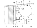
- FIG. 2 is a configuration diagram showing a first lift-out roll provided in the manufacturing apparatus and the surrounding structure.
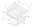
- FIG. 3 is a configuration diagram showing a plurality of lift-out rolls provided in the manufacturing apparatus.
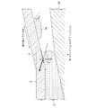
- FIG. 4 is an explanatory diagram for analyzing the conditions under which molten metal droplets adhere when the glass ribbon is pulled up from the molten metal provided in the manufacturing apparatus.
- FIG. 5 shows the relationship between the time until the onset of secondary wetting (latent time) and the oxygen concentration in molten tin droplets.
- FIG. 5A shows the relationship between the oxygen concentration and the time until the occurrence of secondary wetting.
- FIG. 5 shows the relationship between the oxygen concentration and the time until the occurrence of secondary wetting.
- FIG. 5B is an explanatory diagram showing a relation between oxygen concentration and molten tin droplets.
- FIG. 6 is a configuration diagram showing a first lift-out roll and its surrounding structure when performing a verification test of the manufacturing apparatus.
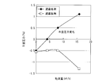
- FIG. 7 is a graph showing the relationship between the pressure in the region next to the lift-out roll and the nitrogen gas flow rate obtained in the verification test of the manufacturing apparatus.
- FIG. 8 is a graph showing the relationship between the gas concentration in the lower region of the glass ribbon and the nitrogen gas flow rate in the region beside the lift-out roll obtained in the verification test of the manufacturing apparatus.
- FIG. 9 is a configuration diagram showing an example of a conventional float glass manufacturing apparatus.
- the float glass manufacturing apparatus 1 of the present embodiment causes the molten glass G supplied to the float bath 2 to flow along the surface of the molten tin 3 held in the float bath 2.
- a plate-shaped glass ribbon 5 is formed, and the glass ribbon 5 is drawn out by a lift-out roll 7 provided in the dross box section 6.
- the glass ribbon 5 is taken out from the outlet portion of the dross box portion 6 and then drawn into the slow cooling furnace 10 by the layer roll 9 to be cooled and washed, and then cut into a predetermined size. A size float glass is obtained.
- the molten glass G sent from the melting furnace (not shown) through the supply passage 11 is supplied to the inlet portion 2 a of the float bath 2 through the lip 12 provided at the terminal portion of the supply passage 11. Yes.
- a twill 13 for adjusting the flow of the molten glass G is installed in the supply passage 11 upstream of the lip 12.
- the supply passage 11 and the float bath 2 are each configured by assembling a plurality of heat-resistant materials such as refractory bricks, but are simplified in FIG.
- the float bath 2 is composed of a molten metal bath 2A filled with molten tin 3 and an upper structure 2B installed on the upper portion of the molten metal bath 2A.
- the atmosphere is cut off as much as possible.
- a front lintel (front wall) 15 is formed at the entrance 2 a of the float bath 2, and the upper portion of the front lintel 15 is connected to the ceiling wall 16.
- a rear end wall 17 is provided on the downstream end side of the float bath 2 so as to be connected to the ceiling wall 16, and an outlet 18 of the glass ribbon 5 is formed in the rear end wall 17 at a position near the liquid level of the molten tin 3. ing.
- the upper structure 2 ⁇ / b> B is configured by the front lintel 15, the ceiling wall 16, and the rear end wall 17.
- the upper structure 2B is provided with a pipe (not shown).
- a reducing mixed gas composed of hydrogen and nitrogen is supplied from the pipe, and the internal space of the float bath 2 is always maintained in a reducing atmosphere at atmospheric pressure or higher. ing.
- the reducing atmosphere inside the float bath 2 slightly flows out from the outlet 18 from which the glass ribbon 5 is drawn to the dross box 6 side.
- the dross box portion 6 provided on the rear stage side of the float bath 2 includes a lower casing 6A and an upper casing 6B.
- three lift-out rolls 7 are provided horizontally on the lower casing 6A.
- the lift-out roll 7 is generally composed of a roll body portion made of, for example, quartz and a shaft that supports the roll body portion.
- the number of liftout rolls 7 is not limited to three as in this embodiment, and any number of liftout rolls 7 may be provided as long as the glass ribbon 5 can be conveyed to the slow cooling furnace 10 side.
- the lower casing 6A has a side wall 6a on the float bath 2 side and a side wall 6b on the slow cooling furnace 10 side on the bottom wall 6c, and other side walls (not shown) erected on both sides in the width direction of these side walls 6a and 6b. ) And is configured in a box shape in which the upper surface side of each side wall is open.
- a graphite seal block 21 and a wall-shaped pedestal 22 are disposed in order to block the air flow between the molten metal bathtub 2A and the slow cooling furnace 10.
- the seal block 21 is installed on the pedestal 22 so that the upper surface of the seal block 21 is in contact with the roll surface of the lift-out roll 7, and the seal block 21 is partitioned so as to be somewhat airtight with the peripheral surface of the lift-out roll 7.
- the base 22 is formed in a wall shape from a thick metal piece such as ductile cast iron, and is provided so as to partition the inside of the lower casing 6A.
- the lower casing 6A three combinations of the base 22, the seal block 21, and the lift-out roll 7 are arranged at predetermined intervals in the conveying direction of the glass ribbon 5, so that the inside of the lower casing 6A is The space is partitioned into four regions R1, R2, R3, and R4. Of these four regions, the region R1 closest to the outlet 18 of the float bath 2 is the first lift-out roll 7 closest to the outlet 18 of the float bath 2, and the seal block 21 installed therebelow. And a region surrounded by the base 22 and the side wall of the lower casing 6A.
- each lift-out roll 7 Since both end portions of each lift-out roll 7 are arranged close to a peripheral wall portion (not shown) of the lower casing 6A, the regions R1, R2, R3, and R4 are box-like regions that are open on the upper surface side. Yes.
- a carbon shielding member 27 supported by a support member 26 is provided on the upper side of the region R1.
- the shielding member 27 has an inverted trapezoidal cross section, and is formed to have a length equivalent to the length of the lift-out roll 7 in the width direction of the glass ribbon.
- the shielding member 27 extends between the lift-out roll 7 and the side wall 6a of the lower casing 6A adjacent to the lift-out roll 7 over substantially the entire length of the lift-out roll 7 accommodated in the lower casing 6A in the width direction of the glass ribbon. This has the effect of closing and making the region R1 a closed space.
- the shielding member 27 has a bottom surface 27 a that is installed on a heat-resistant metal comb-like support member 26 that is horizontally disposed.
- the first side surface 27b and the second side surface 27c rising to the edge in the width direction of the bottom surface 27a, and a ceiling surface 27d formed so as to connect to these side surfaces are formed in an inverted trapezoidal cross section.
- the first side surface 27b of the shielding member 27 rises vertically from one side edge of the bottom surface 27a and is in close contact with the side wall 6a side of the lower casing 6A.
- the second side surface 27c extends from the other side edge of the bottom surface 27a so as to approach the lift-out roll 7 side, and its upper end portion is brought into light contact with the peripheral surface of the lift-out roll 7.
- the support member 26 is fixed to a double wall structure portion incorporated in the side wall 6a of the lower casing 6A.
- the double wall structure is configured by disposing an internal wall 29 with a refrigerant flow path 28 opened with respect to the side wall 6a of the lower casing 6A on the float bath 2 side.
- a comb-like support member 26 is horizontally attached to the inner wall 29 via a base member 30, and the shielding member 27 is installed on the support member 26 as described above.
- a supply pipe 23 for ejecting either an inert gas such as nitrogen or a reducing gas such as hydrogen or a non-oxidizing gas such as a mixed gas thereof is installed below the lift-out roll 7.
- the non-oxidizing gas ejected from the supply pipe 23 is preferably ejected after preheating to 400 to 600 ° C. This is to prevent the glass ribbon 5 from being locally cooled by the ejection of the non-oxidizing gas.
- the supply pipes 23 are provided in each of the regions R1, R2, and R3, and each supply pipe 23 is pulled out to the outside of the dross box portion 6 and is gathered into one extension pipe 32.
- the outlet pipe 32 is connected to a non-oxidizing gas supply source 33 such as nitrogen gas or hydrogen gas.
- a non-oxidizing gas can be supplied from the non-oxidizing gas supply source 33 to each of the regions R1, R2, and R3.
- the non-oxidizing gas is supplied to the region R1 through the supply pipe 23, the region R1 is sealed by the shielding member 27, so that the region R1 can be positively pressured.
- the dross box 6 is provided with a heater (not shown) so that the temperature of the glass ribbon 5 can be adjusted.
- the upper casing 6B of the dross box section 6 is configured as a steel sealing gate, a ceiling wall 24 installed between the float bath 2 and the slow cooling furnace 10, and a stainless steel drape 25 suspended from the ceiling wall 24. And is installed on the upper side of the lower casing 6A.
- the inner three drapes 25 are arranged along the upper position of the contact position between the three lift-out rolls 7 and the glass ribbon 5 moving thereabove. Yes. That is, these drapes 25 are arranged above the center axis of the lift-out roll 7 so as to extend over the entire length of the lift-out roll 7 in the width direction of the glass ribbon, and divide the internal space of the upper casing 6B into a plurality.
- a plurality of layer rolls 9 are installed horizontally in the slow cooling furnace 10, and the glass ribbon 5 that has moved through the dross box portion 6 can be conveyed through the slow cooling furnace 10 by the plurality of layer rolls 9.
- a detection tube 35 for pressure measurement is provided inside the region R1 as shown in FIG. Is preferably measurable.
- an atmosphere gas measuring pipe 36 is provided in a space R5 above the shielding member 27 and defined by a region R5 defined by the shielding member 27, the lift-out roll 7, and the glass ribbon 5 passing therethrough. It is preferable that the atmospheric gas of R5 can be analyzed.
- symbol 37 in FIG. 2 is the below-mentioned test tracer gas introduction pipe
- the shielding member 27 is provided in order to make the region R1 a closed space, but 2 on both sides of the region through which the glass ribbon 5 passes inside the dross box portion 6 in FIG.
- the 2nd shielding member 39 can be comprised with a heat insulating material etc., and can be arrange
- FIG. By closing the openings present on both sides of the glass ribbon 5 inside the dross box 6 with the second shielding member, the lower casing 6A side of the dross box 6 can be more strictly sealed.
- the second shielding member 39 is provided, and the sealing structure on the lower casing 6A side can be further enhanced, whereby oxygen entering the lower surface side of the glass ribbon 5 can be suppressed and melted on the lower surface side of the glass ribbon 5 This has the effect of suppressing the adhesion phenomenon of tin droplets.
- the molten glass G is supplied from the melting furnace to the supply passage 11 and the flow rate of the molten glass G flowing over the lip 12 is twilled.
- the molten glass G is supplied onto the molten tin 3 at the inlet portion 2a of the float bath 2 while being adjusted by the amount of dam 13.
- the molten glass G flowed on the molten tin 3 is formed into a strip-shaped glass ribbon 5 having a predetermined width and a predetermined thickness.
- the glass ribbon 5 is pulled from the liquid surface of the molten tin 3 by the lift-out roll 7 and moved to the dross box 6 side, and then the glass ribbon 5 is cooled while being conveyed through the slow cooling furnace 10 by the layer roll 9. After the glass ribbon 5 cooled in the slow cooling furnace 10 is cooled, the glass ribbon 5 is cut into a length and a width necessary for the cutting step, whereby a float glass having a desired width and length can be manufactured.
- the glass ribbon 5 is formed while supplying the non-oxidizing gas to each region R 1, R 2, R 3, R 4 of the dross box 6.
- the region R1 is a region where the glass ribbon 5 is separated from the liquid surface of the molten tin 3 and pulled up, that is, a region closest to the so-called pickup position. It is considered that the influence on the state of the glass ribbon 5 is the largest. Further, since the glass ribbon 5 is conveyed above the region R1 while being in contact with the lift-out roll 7, the atmosphere on the lower surface side of the glass ribbon 5 at the above-described pickup position is considered to be greatly influenced by the atmosphere of the region R1.
- the shielding member 27 is provided in the region R1 to close the upper portion of the region R1 to be a closed space, and the non-oxidizing gas is supplied to the closed space so that the gas in the region R1 does not move to the lower surface side of the glass ribbon 5.
- the non-oxidizing gas penetrates into the lower surface side of the glass ribbon 5 even if some gas penetrates.
- the non-oxidizing gas is injected into the region R1 to fill the region R1 with the non-oxidizing gas and the region R1 is positively pressured with the non-oxidizing gas, oxygen from the periphery of the dross box portion 6 is introduced into the region R1. Therefore, the oxygen concentration on the lower surface side of the glass ribbon 5 is not improved.
- the pressure When supplying the non-oxidizing gas to the region R1, it is preferable to set the pressure to about atmospheric pressure + 10 Pa. Since the internal space of the float bath 2 is always maintained in a reducing atmosphere at atmospheric pressure or higher, a mixed gas of hydrogen gas and nitrogen gas constituting the reducing atmosphere flows out from the outlet 18 of the float bath 2. Yes.
- the glass ribbon 5 passes through the dross box 6 and a plurality of lift-out rolls 7 are provided inside the dross box 6, the inside of the dross box 6 is completely sealed. It cannot be. For this reason, it is effective to provide the shielding member 27 to make the region R1 a closed space, to provide the supply pipe 23 to supply the non-oxidizing gas to the region R1, and to make the region R1 positive with non-oxidizing gas It is.
- the region R1 is referred to as a closed space, but the lift-out roll 7 and the shielding member 27 in contact with the region R1 are only in contact with each other. A slight amount of gas flows out from between 7 and the shielding member 27. Further, since only the lift-out roll 7 and the seal block 21 are in contact with each other, a slight amount of gas can escape from between the lift-out roll 7 and the shielding member 27 by making the region R1 positive. Have sex. Further, gas is slightly released from the portions in contact with the side walls of the dross box portion 6 on both ends of the lift-out roll 7. In the present embodiment, the state in which the region R1 is closed to such an extent that gas escape from these portions is collectively referred to as a closed space.
- the portion where the glass ribbon 5 separates from the liquid surface of the molten tin 3 and the surrounding oxygen concentration can be made lower than before. . For this reason, there is less possibility that molten tin droplets adhere to the lower surface side of the glass ribbon 5, and there is less possibility that tin oxide will adhere to the lower surface side of the glass ribbon 5.
- the amount of oxygen on the lower surface side of the glass ribbon 5 cannot be reduced.
- a pressure difference also arises, and due to these, oxygen slightly enters the inside of the lower casing 6A from the surroundings. Come in.
- the temperature is about 600 ° C. in the dross box section 6, even if hydrogen is introduced as a reducing gas into this oxygen amount environment, the oxygen remains present without being consumed.
- the non-oxidizing gas when the non-oxidizing gas is introduced into the region R1 without providing the shielding member 27 and the introduction pressure of the non-oxidizing gas is increased, the non-oxidizing gas slightly containing oxygen from the opening side of the region R1 is glass. Since it goes to the ribbon 5 side, the purpose of reducing oxygen cannot be achieved. Rather, if the air flow rate of the non-oxidizing gas is increased, dust may be blown off and the glass ribbon 5 may be contaminated. In this respect, it is significant that oxygen on the lower surface side of the glass ribbon 5 can be reduced by providing the shielding member 27 and adding the atmospheric pressure to the region R1 as a closed space to make the region R1 a positive pressure.
- the non-oxidizing gas to be added to the region R1 from the supply pipe 23 may always flow, or is stopped when the pressure is measured and reaches a desired positive pressure state, and is added again only when the pressure decreases. Any supply state such as supply may be used.
- mgsin ⁇ + ⁇ LG cos ⁇ + ⁇ LS ⁇ GS , and the direction of this equilibrium equation is determined by ⁇ LG cos ⁇ , which is a variable value, and since ⁇ LG is constant, the value of ⁇ is considered to be dominant. It is done.
- the larger the wetting angle ⁇ (90 ° to 180 °) of tin the greater the force on the side pulled back to the molten tin, and there is a tendency that molten tin droplets do not adhere to the glass ribbon 5. Recognize. In order to determine whether or not the molten tin droplets adhere to the glass ribbon side, the inventor conducted the following test.
- the wetting angle of the molten tin droplet 40 is constant at 113 ° in an environment of 500 to 900 ° C.
- oxygen is present in the periphery of the molten tin droplet 40, oxygen begins to enter the droplet 40 as shown in FIG.
- the oxygen concentration in the droplet increases as time passes after it begins to penetrate, but the wetting angle ⁇ hardly changes, and an oxide film starts to form on the droplet surface when the saturation solubility is exceeded at a certain time.
- a phenomenon that can be referred to as a secondary wetting phenomenon occurs, and the wetting angle ⁇ 2 decreases. This phenomenon is called a secondary wetting phenomenon.
- the graph of FIG. 5A shows the result of measuring the relationship between the time until secondary wetting (latency time) and the oxygen concentration (ppm). This test shows the result of measuring the time until the occurrence of secondary wetting for each oxygen concentration when the oxygen concentration is changed at 700 ° C. From the graph shown in FIG.
- the liftout roll 7 closest to the float bath 2 the glass ribbon 5 passing thereover, and the upper side wall of the lower casing 6A
- a region surrounded by the shielding member 27 is defined as a room A.
- a region R1 surrounded by the liftout roll 7 closest to the float bath 2, the seal block 21 below it, the base 22, the bottom wall 6a of the lower casing 6A and the side wall 6a, and the shielding member 27 is defined as a B chamber.
- a quartz roll having a diameter of 250 mm and a length of 3 m was used as the lift-out roll 7, and the glass ribbon was conveyed so that the glass ribbon having a thickness of 0.7 mm moved on the lift-out roll 7.
- the shielding member is made of carbon having an inverted trapezoidal shape having a bottom side of 20 mm, an upper surface of 40 mm, and an oblique side of 30 mm that contacts the surface of the lift-out roll 7. The following tests were conducted while conveying the glass ribbon 5 by the above method.
- FIG. 7 shows the pressure change in the B chamber accompanying the first test when the shielding plate is provided and when the shielding plate is omitted.
- FIG. 8 shows the change in the CO 2 concentration in the room A accompanying the second test when the shielding plate is provided and when the shielding plate is omitted.
- the pressure in the chamber A once decreases as the nitrogen gas flow rate is increased, but the pressure rapidly increases when the nitrogen gas flow rate exceeds 8 m 3 / h. As shown in FIG. 7, this correlates with the result that the pressure in the B chamber rapidly decreases when the nitrogen gas flow rate exceeds 8 m 3 / h.
- the CO 2 concentration in the A chamber can be decreased sequentially by increasing the nitrogen gas flow rate. When the nitrogen gas flow rate exceeds 8 m 3 / h, the CO 2 concentration in the A chamber is reduced to approximately 0 ppm. We were able to.
- the technology of the present invention can be widely applied to glass ribbon production technology in general by the float process.
- G ... Molten glass, R1, R2, R3, R4, R5 ... Area, 1 ... Float glass manufacturing device, 2 ... Float bath, 2A ... Molten metal bath, 2a ... Inlet part, 3 ... Molten tin, 5 ... Glass ribbon , 6 ... Dross box part, 6A ... Lower casing, 6a ... Side wall, 6B ... Upper casing, 6b ... Side wall, 7 ... Lift-out roll, 9 ... Layer roll, 10 ... Slow cooling furnace, 11 ... Supply passage, 12 ... Lip, 13 ... Twill, 15 ... front lintel, 17 ... rear end wall, 18 ... outlet, 21 ... seal block, 22 ... pedestal, 23 ... supply pipe, 25 ... drape, 26 ... support member, 27 ... shielding member, 29 ... inner wall 35 ... Pressure detection tube, 36 ... Atmospheric gas measurement tube, 37 ... Tracer gas introduction tube, 39 ... Second shielding member.
Landscapes
- Chemical & Material Sciences (AREA)
- Engineering & Computer Science (AREA)
- Materials Engineering (AREA)
- Organic Chemistry (AREA)
- Re-Forming, After-Treatment, Cutting And Transporting Of Glass Products (AREA)
- Glass Compositions (AREA)
Abstract
Description
上述のフロート法によるフロートガラスの製造方法は、ガラスの一面を溶融金属の浴面によって形成し、溶融金属上に溶融ガラスを広げることによりガラスの他の面を形成するので、ガラスの平坦性を極めて高くすることが可能であり、大量生産にも好適な製造方法として知られている。このため、フロート法は、自動車用ガラス、ディスプレイ用ガラスなどの板ガラス生産に広く適用されている。
図9に示す製造装置において溶融金属浴100の浴面に溶融ガラス107を供給し、必要な厚さと幅に引き延ばした後、リフトアウトロール105の牽引力によりガラスリボン108を引き出して徐冷炉103の側に搬送できる。
前記不活性ガスの供給部は、フロートバスの出口部側からドロスボックスの内側に流入しようとするガスの流れを逆流させ、フロートバス側に存在する揮発錫を含有するガスをドロスボックス側に混入させないように動作する。ドロスボックス側はフロートバスの内部に比べて低温になりやすいので、ドロスボックス側に揮発錫が移動して微細な金属酸化物、あるいはドロスなどとしてガラスリボンの表面に付着すると、ガラス表面を汚染するので、この汚染を防止できる。
本発明は前記背景に基づきなされたもので、錫酸化物の付着による欠点が少ない高品質のフロートガラスを提供できる製造方法と製造装置の提供を目的とする。
そこで、ドロスボックス部においてガラスリボンが溶融錫の液面から分離する位置に最も近いリフトアウトロールについて、該リフトアウトロールより溶融錫側の空間を閉空間としてそこに非酸化性ガスを満たすことにより、ガラスリボンの下面側に付着してリフトアウトロール側に搬送される溶融錫の液滴を抑制できる。
ガラスリボンが溶融錫の液面から分離する位置に最も近いリフトアウトロールとそれに隣接対向するドロスボックス部の側壁との間に遮蔽部材を設置して閉空間を構成するならば、この閉空間からガラスリボンの下面側に酸素を供給することがなくなる。このため、ガラスリボンの下面が溶融錫の液面から分離する位置において酸素濃度を低減でき、ガラスリボンの下面側に付着してリフトアウトロール側に搬送される溶融錫の液滴を抑制できる。
ガラスリボンの両脇側において第2の遮蔽部材を設置することにより、ガラスリボンの下面が溶融錫の液面から分離する側の酸素濃度を低減でき、ガラスリボンの下面側に付着してリフトアウトロール側に搬送される溶融錫の液滴を抑制できる。
溶融錫の液滴が2次濡れを発現する場合、酸素濃度による影響があり、酸素濃度がある程度高いと、2次濡れ発現までの時間が短くなる。酸素濃度を3ppm以下に抑えることで2次濡れの発生時間を充分に長くすることができるので、ガラスリボンの下面が溶融錫の液面から分離する位置において、溶融錫から錫の液滴が分離することを抑制できる。
前記遮蔽部材はリフトアウトロールに接触しつつリフトアウトロールの回転を許容しながらリフトアウトロールとドロスボックス部の側壁との間の領域を閉空間にする。このため、リフトアウトロールの動作に支障なく閉空間を構成し、ガラスリボンに溶融錫の液滴の付着を防止する。
シールブロックを設けることで台座上においてリフトアウトロールの回転を許容しつつ台座とリフトアウトロールの間を気密に仕切ることができる。このため、閉空間に対する酸素の混入を防止できる。
遮蔽部材をカーボンから構成することにより、耐熱性に優れ、高温のガラスリボンが通過する領域近傍に配置される遮蔽部材として熱による変形などの影響を受けることなく閉空間を閉じることができる。
ガラスリボンの両脇側に第2の遮蔽部材を設置することにより、ガラスリボンの下面が溶融錫の液面から分離する側の酸素濃度を低減でき、ガラスリボンの下面側に付着してリフトアウトロール側に搬送される溶融錫の液滴を抑制できる。
リフトアウトロールとドレスボックス部の側壁との間を閉空間とするには、ドロスボックス部の側壁に遮蔽部材を設け、ドロスボックス部の側壁とリフトアウトロールとの間を閉じることで実現できる。
図1に示すように、本実施形態のフロートガラスの製造装置1は、フロートバス2に供給された溶融ガラスGを、フロートバス2に湛えられた溶融錫3の表面に沿って流動させて帯板状のガラスリボン5を成形し、このガラスリボン5をドロスボックス部6に設けたリフトアウトロール7で引き出す装置として構成されている。本実施形態の装置においてガラスリボン5はドロスボックス部6の出口部から取り出された後、レヤーロール9にて徐冷炉10に引き込まれて冷却され、洗浄された後、所定の寸法に切断され、目的の大きさのフロートガラスが得られる。
フロートバス2の入口部2aにはフロントリンテル(前面壁)15が形成され、フロントリンテル15の上部が天井壁16に接続されている。フロートバス2の下流端側には後端壁17が天井壁16と接続するように設けられ、後端壁17において溶融錫3の液面近くの位置にガラスリボン5の出口部18が形成されている。フロートバス2においてフロントリンテル15と天井壁16と後端壁17とから上部構造体2Bが構成されている。
支持部材26は下部ケーシング6Aの側壁6aに組み込まれた2重壁構造部に固定されている。この2重壁構造部は、フロートバス2側の下部ケーシング6Aの側壁6aに対し冷媒流路28をあけて内部壁29を配置することにより構成されている。この内部壁29にベース部材30を介し櫛状の支持部材26が水平に取り付けられ、この支持部材26の上に前述の如く遮蔽部材27が設置されている。
また、ドロスボックス部6には図示略のヒータが設けられており、ガラスリボン5の温度を調節できるように構成されている。
徐冷炉10にはレヤーロール9が水平に複数設置されており、ドロスボックス部6を通過して移動してきたガラスリボン5を複数のレヤーロール9によって徐冷炉10内を搬送できる。
第2の遮蔽部材39を設け、下部ケーシング6A側の密閉構造をより高めることができ、これによりガラスリボン5の下面側に侵入する酸素を抑制することができ、ガラスリボン5の下面側に溶融錫の液滴の付着現象を抑制できる効果がある。
図1~図3に示す構成の製造装置を用いてガラスリボン5を製造するには、溶融炉から溶融ガラスGを供給通路11に供給し、リップ12の上を流れる溶融ガラスGの流量をツイール13の堰き止め量により調整しながらフロートバス2の入口部2aの溶融錫3上に溶融ガラスGを供給する。フロートバス2においては溶融錫3の上に流動させた溶融ガラスGを所定幅、所定厚さの帯板状のガラスリボン5に成形する。このガラスリボン5をリフトアウトロール7で溶融錫3の液面から牽引してドロスボックス部6側に移動させ、次いでレヤーロール9により徐冷炉10の内部を搬送しながらガラスリボン5を冷却する。徐冷炉10において冷却されたガラスリボン5は冷却後、切断工程において必要な長さ、幅に切断することで目的の幅と長さのフロートガラスを製造できる。
領域R1を閉空間として非酸化性ガスを満たし、領域R1を正圧化することで溶融錫3の液面からガラスリボン5が離れる部分とその周囲の酸素濃度を従来よりも低くすることができる。このため、ガラスリボン5の下面側に溶融錫の液滴を付着させるおそれが少なくなり、錫酸化物をガラスリボン5の下面側に付着させるおそれも少なくなる。
供給管23から領域R1に付加する非酸化性ガスは常時流しておいても良いし、圧力を測定して目的の正圧状態になった時点で停止し、圧力が低下した場合にのみ再度追加供給するなど、いずれの供給状態であっても良い。
図4はレンガ等の耐火材34の上に溶融錫3が存在し、この液面に沿って薄いガラスリボン5が移動し、任意の位置で斜め上方にガラスリボン5が引き上げられた場合、溶融錫3の端部から溶融錫3の液滴が分離し、ドロス3aとしてガラスリボン5の下面に付着したままガラスリボン5とともに若干移動した状態を示す。
溶融錫の液滴がガラスリボン5の下面に付着していかないためには、3重点(ガラスリボン5が溶融錫3から離れる点)において、ガラス面と平行に働く力のバランスが、溶融錫3側に引き戻す方向に働くと、溶融錫の液滴がガラスリボン5に持って行かれないと考えられる。
結果として、錫の濡れ角θ(90゜~180゜)が大きいほど、溶融錫に引き戻す側の力が大きくなり、ガラスリボン5に溶融錫の液滴が付着してゆかない傾向となることがわかる。
この溶融錫の液滴がガラスリボン側に付着するか否かの現象を確定するために、本発明者は以下の試験を行った。以下の試験は、本発明者の知見により、溶融錫がガラスリボン5の下面に接している状態において、溶融錫の液滴に2次濡れという現象が発現し、時間経過と共に溶融錫の液滴の濡れ角が変わる現象を生じることについて以下に説明する。
ガラスの表面に対し酸素が存在しない状態で溶融錫の液滴40の濡れ角は500~900℃の環境において113゜で一定である。この溶融錫の液滴40に対し周囲に酸素が存在すると図5(B)に示すように液滴40の中には、酸素が侵入し始める。浸入し始めた後、時間が経過すると共に液滴中の酸素濃度が増加するが、濡れ角θは殆ど変化せず、ある時刻に飽和溶解度を超えたところで液滴表面に酸化膜が生成し始めると同時に表面エネルギーが急激に変化するため、2次濡れ現象と呼称できる現象が発生して濡れ角θ2が小さくなる。この現象を2次濡れ現象と呼称する。
図5(A)のグラフに2次濡れまでの時間(潜伏時間)と酸素濃度(ppm)の関係を測定した結果を示す。この試験は、700℃で酸素濃度を変えた場合の酸素濃度毎の2次濡れ発生までの時間を測定した結果を示す。
図5(A)に示すグラフから、2次濡れ発生までの時間は、酸素濃度30ppmにおいて0に近い短時間で発生するが、酸素濃度10ppmで250秒程度、5ppmでは300秒程度かかるが、酸素濃度3ppmから急激に長くなり、500秒程度となり、1ppmでは1500秒程度と大幅に増大することがわかった。このため、2次濡れを発生する時間が長いほど、ガラスリボンの下面側に溶融錫の液滴は付着し難いと考えられる。
このため、上述のように遮蔽部材27を設けて領域R1を密閉化し、非酸化性ガスを供給して領域R1を正圧化することが重要であると考えられる。
図1、図2に示す構成のガラスリボンの製造装置を用い、図6に示すようにフロートバス2に最も近いリフトアウトロール7とその上を通過するガラスリボン5と下部ケーシング6Aの側壁上部と遮蔽部材27とにより囲まれる領域をA室と定義する。次に、フロートバス2に最も近いリフトアウトロール7とその下方のシールブロック21と台座22と下部ケーシング6Aの底壁および側壁6aと前記遮蔽部材27により囲まれる領域R1をB室と定義する。
リフトアウトロール7はφ250mm、長さ3mの石英製のロールを用い、リフトアウトロール7の上を厚さ0.7mmのガラスリボンが移動するようにガラスリボンを搬送した。遮蔽部材は底辺20mm、上面40mm、リフトアウトロール7の表面に接する斜辺30mmの逆台形状のカーボン製のものを用い、自重により斜辺をリフトアウトロール7の表面に当接させつつリフトアウトロール7によりガラスリボン5を搬送しながら以下の試験を行った。
図7は遮蔽板を設けた場合と遮蔽板を略した場合のそれぞれについて、第1の試験に伴うB室の圧力変化を示す。
以上のことから、遮蔽板を設けることで、A室とB室を仕切ってB室を閉空間とすることができていることがわかる。
図8に示すように遮蔽板を設けていない場合は、窒素ガス流量を増大させるにつれてA室の圧力は一端低下するが、窒素ガス流量が8m3/hを超えると急激に圧力が上昇した。これは、図7に示すように窒素ガス流量が8m3/hを超えるとB室の圧力が急激に低下する結果と相関している。
これに対し、遮蔽板を設けた場合は窒素ガス流量を増大すると、A室のCO2濃度を順次低下でき、窒素ガス流量が8m3/hを超えるとA室のCO2濃度をほぼ0ppmにすることができた。
このため、図6に示す構造の製造装置を用いると、ガラスリボンが溶融錫の液面から分離する領域に対し、酸素をほぼ0ppmにすることができるので、図5を元に先に説明したように溶融錫の液滴の2次漏れ発現までの時間を長くできる。このため、ガラスリボンの下面に溶融錫の液滴を付着させてしまうおそれが少なくなり、錫酸化物付着に起因する欠点の無い、高品質のフロートガラスを製造できる特徴を有する。
Claims (10)
- 溶融金属を収容したフロートバスで成形されたガラスリボンを前記フロートバスの下流側に設けたドロスボックス部に水平に配設したリフトアウトロールで前記フロートバスの浴面から持ち上げて搬送する工程を含むフロートガラスの製造方法であって、
前記リフトアウトロールを設けたドロスボックス部において前記フロートバスに最も近いリフトアウトロールとそれに隣接対向するドロスボックス部の側壁との間を、前記ドロスボックス部の側壁と前記リフトアウトロールと該リフトアウトロールの台座により囲まれる閉空間として区画して該閉空間に不活性ガスを送り、この閉空間を不活性ガスで満たしながら前記リフトアウトロールにより前記フロートバスから前記ガラスリボンを搬送するフロートガラスの製造方法。 - 前記フロートバスに最も近い前記ドロスボックス部の側壁の内側に前記リフトアウトロールの周面に接触する遮蔽部材を設置して前記ドロスボックス部の側壁と前記リフトアウトロールの間を閉塞する請求項1に記載のフロートガラスの製造方法。
- 前記リフトアウトロールとその下方の台座の間に前記リフトアウトロールに当接して該リフトアウトロールの回転を許容しながら該リフトアウトロールと前記台座との間をシールするシールブロックを介在させる請求項1または2に記載のフロートガラスの製造方法。
- 前記ガラスリボン両脇と前記ドロスボックス部の側壁との間に第2の遮蔽部材を設置する請求項1~3のいずれか一項に記載のフロートガラスの製造方法。
- 前記閉空間の酸素濃度を3ppm以下とすることを特徴とする請求項1~4のいずれか一項に記載のフロートガラスの製造方法。
- 溶融錫の液面に溶融ガラスを供給してガラスリボンを成形するフロートバスと、前記溶融錫からガラスリボンを持ち上げて搬送するリフトアウトロールを備えて前記フロートバスの下流側に設置されたドロスボックス部を備えたフロートガラスの製造装置であって、
前記ドロスボックス部が、ケーシング本体とその内側に水平に配置された1つ以上のリフトアウトロールと該リフトアウトロールの底部を支持する台座を備えて構成され、前記ケーシング本体の内部空間が、前記リフトアウトロールとその下方の台座により複数の領域に仕切られ、前記フロートバスの出口部に最も近い前記リフトアウトロールとそれに隣接対向する前記ドロスボックス部の側壁との間に前記領域を閉空間とする遮蔽部材が配置され、前記遮蔽部材を設けた閉空間に不活性ガスを供給するガス供給手段が接続されたフロートガラスの製造装置。 - 前記フロートバスに最も近い前記ドロスボックス部の側壁の内側に前記リフトアウトロールの周面に接触して前記ドロスボックス部と前記リフトアウトロールの間を閉じる前記遮蔽部材が設置された請求項6に記載のフロートガラスの製造装置。
- 前記リフトアウトロールとその下方の台座の間に前記リフトアウトロールに当接して該リフトアウトロールの回転を許容しながら該リフトアウトロールと前記台座との間を閉じるシールブロックが介在された請求項6または7に記載のフロートガラスの製造装置。
- 前記遮蔽部材がカーボンからなり、前記リフトアウトロールの前記ガラスリボンの幅方向における長さと同じ長さに形成され、前記遮蔽部材の一面を前記リフトアウトロールの周面の一部かつ前記ガラスリボンの幅方向における全長にわたり接触させて前記遮蔽部材が配置された請求項6~8のいずれか一項に記載のフロートガラスの製造装置。
- 前記リフトアウトロールに沿って移動するガラスリボンの両脇側に第2の遮蔽部材が設置された請求項6~9のいずれか一項に記載のフロートガラスの製造装置。
Priority Applications (2)
| Application Number | Priority Date | Filing Date | Title |
|---|---|---|---|
| CN201380056884.6A CN104768884B (zh) | 2012-10-31 | 2013-10-25 | 浮法玻璃的制造方法和制造装置 |
| KR1020157010535A KR102147684B1 (ko) | 2012-10-31 | 2013-10-25 | 플로트 유리의 제조 방법과 제조 장치 |
Applications Claiming Priority (2)
| Application Number | Priority Date | Filing Date | Title |
|---|---|---|---|
| JP2012-240529 | 2012-10-31 | ||
| JP2012240529A JP2016011214A (ja) | 2012-10-31 | 2012-10-31 | フロートガラスの製造方法と製造装置 |
Publications (1)
| Publication Number | Publication Date |
|---|---|
| WO2014069372A1 true WO2014069372A1 (ja) | 2014-05-08 |
Family
ID=50627280
Family Applications (1)
| Application Number | Title | Priority Date | Filing Date |
|---|---|---|---|
| PCT/JP2013/078994 Ceased WO2014069372A1 (ja) | 2012-10-31 | 2013-10-25 | フロートガラスの製造方法と製造装置 |
Country Status (5)
| Country | Link |
|---|---|
| JP (1) | JP2016011214A (ja) |
| KR (1) | KR102147684B1 (ja) |
| CN (1) | CN104768884B (ja) |
| TW (1) | TW201425240A (ja) |
| WO (1) | WO2014069372A1 (ja) |
Cited By (9)
| Publication number | Priority date | Publication date | Assignee | Title |
|---|---|---|---|---|
| CN105254170A (zh) * | 2015-10-13 | 2016-01-20 | 秦皇岛玻璃工业研究设计院 | 一种浮法玻璃过渡辊台及向其首次引入玻璃头子的方法 |
| CN105384326A (zh) * | 2014-09-01 | 2016-03-09 | 旭硝子株式会社 | 气氛分隔装置、浮法玻璃制造装置及浮法玻璃制造方法 |
| WO2016170634A1 (ja) * | 2015-04-22 | 2016-10-27 | 旭硝子株式会社 | フロートガラスの製造方法 |
| CN110668679A (zh) * | 2019-11-26 | 2020-01-10 | 中国洛阳浮法玻璃集团有限责任公司 | 一种浮法玻璃的制造装置及其制造方法 |
| CN110713335A (zh) * | 2019-11-06 | 2020-01-21 | 蚌埠中建材信息显示材料有限公司 | 一种玻璃流道密封装置 |
| CN110894134A (zh) * | 2019-12-27 | 2020-03-20 | 蚌埠中光电科技有限公司 | 一种浮法玻璃成型工艺用锡槽装置 |
| CN111995228A (zh) * | 2020-07-28 | 2020-11-27 | 上海宝冶冶金工程有限公司 | 一种浮法玻璃窑锡槽耐材施工方法 |
| JP2021109817A (ja) * | 2020-01-15 | 2021-08-02 | Agc株式会社 | フロートガラス製造装置及びフロートガラス製造方法 |
| JP7666147B2 (ja) | 2021-06-09 | 2025-04-22 | Agc株式会社 | フロートガラス製造方法 |
Families Citing this family (4)
| Publication number | Priority date | Publication date | Assignee | Title |
|---|---|---|---|---|
| JP6536427B2 (ja) * | 2015-04-21 | 2019-07-03 | Agc株式会社 | フロートガラスの製造装置、フロートガラスの製造方法 |
| KR102070683B1 (ko) * | 2016-02-02 | 2020-01-29 | 주식회사 엘지화학 | 플로트 유리 제조 장치 및 방법 |
| CN108298808B (zh) * | 2018-03-26 | 2023-09-19 | 河北视窗玻璃有限公司 | 一种过渡辊台及浮法玻璃生产系统 |
| EP3795544A4 (en) * | 2018-05-17 | 2022-03-02 | Agc Inc. | FLOAT GLASS PRODUCTION DEVICE AND FLOAT GLASS PRODUCTION METHOD |
Citations (2)
| Publication number | Priority date | Publication date | Assignee | Title |
|---|---|---|---|---|
| JP2011157250A (ja) * | 2010-02-03 | 2011-08-18 | Asahi Glass Co Ltd | フロートガラス用搬送ロールの付着物除去部材 |
| WO2012066889A1 (ja) * | 2010-11-18 | 2012-05-24 | 旭硝子株式会社 | ガラス板の製造装置およびガラス板の製造方法 |
Family Cites Families (4)
| Publication number | Priority date | Publication date | Assignee | Title |
|---|---|---|---|---|
| CN1007972B (zh) * | 1985-08-14 | 1990-05-16 | 圣戈班玻璃制造公司 | 在浮式炉出口处拉制玻璃条板的方法和装置,及制成的平板玻璃 |
| KR101038404B1 (ko) * | 2006-12-08 | 2011-06-03 | 아사히 가라스 가부시키가이샤 | 유리 시트의 제조 방법 |
| CN101754937B (zh) | 2007-07-23 | 2012-02-29 | 旭硝子株式会社 | 浮法玻璃制造方法及浮法玻璃制造设备 |
| KR101383603B1 (ko) | 2010-06-03 | 2014-04-11 | 주식회사 엘지화학 | 플로트 유리 제조 장치 및 방법 |
-
2012
- 2012-10-31 JP JP2012240529A patent/JP2016011214A/ja active Pending
-
2013
- 2013-10-25 KR KR1020157010535A patent/KR102147684B1/ko not_active Expired - Fee Related
- 2013-10-25 WO PCT/JP2013/078994 patent/WO2014069372A1/ja not_active Ceased
- 2013-10-25 CN CN201380056884.6A patent/CN104768884B/zh active Active
- 2013-10-31 TW TW102139640A patent/TW201425240A/zh unknown
Patent Citations (2)
| Publication number | Priority date | Publication date | Assignee | Title |
|---|---|---|---|---|
| JP2011157250A (ja) * | 2010-02-03 | 2011-08-18 | Asahi Glass Co Ltd | フロートガラス用搬送ロールの付着物除去部材 |
| WO2012066889A1 (ja) * | 2010-11-18 | 2012-05-24 | 旭硝子株式会社 | ガラス板の製造装置およびガラス板の製造方法 |
Cited By (13)
| Publication number | Priority date | Publication date | Assignee | Title |
|---|---|---|---|---|
| CN105384326A (zh) * | 2014-09-01 | 2016-03-09 | 旭硝子株式会社 | 气氛分隔装置、浮法玻璃制造装置及浮法玻璃制造方法 |
| WO2016170634A1 (ja) * | 2015-04-22 | 2016-10-27 | 旭硝子株式会社 | フロートガラスの製造方法 |
| CN105254170A (zh) * | 2015-10-13 | 2016-01-20 | 秦皇岛玻璃工业研究设计院 | 一种浮法玻璃过渡辊台及向其首次引入玻璃头子的方法 |
| CN110713335A (zh) * | 2019-11-06 | 2020-01-21 | 蚌埠中建材信息显示材料有限公司 | 一种玻璃流道密封装置 |
| CN110668679B (zh) * | 2019-11-26 | 2023-10-27 | 中国洛阳浮法玻璃集团有限责任公司 | 一种浮法玻璃的制造装置及其制造方法 |
| CN110668679A (zh) * | 2019-11-26 | 2020-01-10 | 中国洛阳浮法玻璃集团有限责任公司 | 一种浮法玻璃的制造装置及其制造方法 |
| CN110894134A (zh) * | 2019-12-27 | 2020-03-20 | 蚌埠中光电科技有限公司 | 一种浮法玻璃成型工艺用锡槽装置 |
| CN110894134B (zh) * | 2019-12-27 | 2024-01-12 | 蚌埠中光电科技有限公司 | 一种浮法玻璃成型工艺用锡槽装置 |
| JP2021109817A (ja) * | 2020-01-15 | 2021-08-02 | Agc株式会社 | フロートガラス製造装置及びフロートガラス製造方法 |
| JP7404881B2 (ja) | 2020-01-15 | 2023-12-26 | Agc株式会社 | フロートガラス製造装置及びフロートガラス製造方法 |
| CN111995228A (zh) * | 2020-07-28 | 2020-11-27 | 上海宝冶冶金工程有限公司 | 一种浮法玻璃窑锡槽耐材施工方法 |
| CN111995228B (zh) * | 2020-07-28 | 2022-09-23 | 上海宝冶冶金工程有限公司 | 一种浮法玻璃窑锡槽耐材施工方法 |
| JP7666147B2 (ja) | 2021-06-09 | 2025-04-22 | Agc株式会社 | フロートガラス製造方法 |
Also Published As
| Publication number | Publication date |
|---|---|
| KR20150081268A (ko) | 2015-07-13 |
| CN104768884B (zh) | 2017-08-15 |
| TW201425240A (zh) | 2014-07-01 |
| KR102147684B1 (ko) | 2020-08-26 |
| JP2016011214A (ja) | 2016-01-21 |
| CN104768884A (zh) | 2015-07-08 |
Similar Documents
| Publication | Publication Date | Title |
|---|---|---|
| JP2016011214A (ja) | フロートガラスの製造方法と製造装置 | |
| CN102260038B (zh) | 用于浮法玻璃的退火设备和退火方法 | |
| US8201419B2 (en) | Apparatus for manufacturing float glass | |
| JPWO2019221084A1 (ja) | フロートガラス製造装置及びフロートガラス製造方法 | |
| CN109879594A (zh) | 一种浮法玻璃过渡辊台及其过渡辊台渣箱的清洁装置 | |
| CN104743776B (zh) | 浮法平板玻璃的制造方法 | |
| JP6758188B2 (ja) | ガラス基板の製造方法及びガラス基板製造装置 | |
| EP3173384A1 (en) | Glass melt production device, glass melt production method, glass product production device, and glass product production method | |
| JP5664375B2 (ja) | ガラス板製造装置、及びガラス板製造方法 | |
| JP6049130B2 (ja) | 繊維ベースガスケット、ガラス製造システム、および、熱電池誘導のブリスタを低減させる方法 | |
| US8266925B2 (en) | Apparatus for manufacturing float glass | |
| US8201420B2 (en) | Apparatus for manufacturing float glass | |
| JP6206179B2 (ja) | 溶融ガラス供給装置、及びガラス板製造装置 | |
| JP6589876B2 (ja) | ガラス溶融物製造装置、ガラス溶融物製造方法、ガラス物品製造装置およびガラス物品製造方法 | |
| CN104640818B (zh) | 浮法玻璃的制造装置和制造方法 | |
| CN214011248U (zh) | 一种模拟玻璃液浮抛和渗锡的实验装置 | |
| JP2007239006A (ja) | 連続溶融金属めっき設備 | |
| CN209113743U (zh) | 一种改善盖板玻璃退火翘曲及辊子污染的装置 | |
| JP6844367B2 (ja) | スライディングノズル、下部プレート、下部ノズル及び溶鋼の給湯方法 | |
| JP5615314B2 (ja) | 合成シリカガラスの製造装置及び合成石英ガラスの製造方法 | |
| CN203174156U (zh) | 一种退火炉入口密封装置 | |
| JP7259292B2 (ja) | 再溶解炉および再溶解方法 | |
| CN117902812A (zh) | 玻璃板制造装置及方法 | |
| RU167476U1 (ru) | Устройство для определения плотности и поверхностного натяжения металлических расплавов | |
| JP2004204279A (ja) | 連続溶融金属めっき方法および装置 |
Legal Events
| Date | Code | Title | Description |
|---|---|---|---|
| 121 | Ep: the epo has been informed by wipo that ep was designated in this application |
Ref document number: 13850512 Country of ref document: EP Kind code of ref document: A1 |
|
| ENP | Entry into the national phase |
Ref document number: 20157010535 Country of ref document: KR Kind code of ref document: A |
|
| NENP | Non-entry into the national phase |
Ref country code: DE |
|
| 122 | Ep: pct application non-entry in european phase |
Ref document number: 13850512 Country of ref document: EP Kind code of ref document: A1 |
|
| NENP | Non-entry into the national phase |
Ref country code: JP |