WO2014069158A1 - 組み付け部品のロック構造 - Google Patents
組み付け部品のロック構造 Download PDFInfo
- Publication number
- WO2014069158A1 WO2014069158A1 PCT/JP2013/077075 JP2013077075W WO2014069158A1 WO 2014069158 A1 WO2014069158 A1 WO 2014069158A1 JP 2013077075 W JP2013077075 W JP 2013077075W WO 2014069158 A1 WO2014069158 A1 WO 2014069158A1
- Authority
- WO
- WIPO (PCT)
- Prior art keywords
- engagement
- engaging
- hole
- lock structure
- piece
- Prior art date
- Legal status (The legal status is an assumption and is not a legal conclusion. Google has not performed a legal analysis and makes no representation as to the accuracy of the status listed.)
- Ceased
Links
Images

Classifications
-
- F—MECHANICAL ENGINEERING; LIGHTING; HEATING; WEAPONS; BLASTING
- F16—ENGINEERING ELEMENTS AND UNITS; GENERAL MEASURES FOR PRODUCING AND MAINTAINING EFFECTIVE FUNCTIONING OF MACHINES OR INSTALLATIONS; THERMAL INSULATION IN GENERAL
- F16B—DEVICES FOR FASTENING OR SECURING CONSTRUCTIONAL ELEMENTS OR MACHINE PARTS TOGETHER, e.g. NAILS, BOLTS, CIRCLIPS, CLAMPS, CLIPS OR WEDGES; JOINTS OR JOINTING
- F16B5/00—Joining sheets or plates, e.g. panels, to one another or to strips or bars parallel to them
- F16B5/06—Joining sheets or plates, e.g. panels, to one another or to strips or bars parallel to them by means of clamps or clips
- F16B5/0607—Joining sheets or plates, e.g. panels, to one another or to strips or bars parallel to them by means of clamps or clips joining sheets or plates to each other
- F16B5/0621—Joining sheets or plates, e.g. panels, to one another or to strips or bars parallel to them by means of clamps or clips joining sheets or plates to each other in parallel relationship
- F16B5/0664—Joining sheets or plates, e.g. panels, to one another or to strips or bars parallel to them by means of clamps or clips joining sheets or plates to each other in parallel relationship at least one of the sheets or plates having integrally formed or integrally connected snap-in-features
-
- F—MECHANICAL ENGINEERING; LIGHTING; HEATING; WEAPONS; BLASTING
- F16—ENGINEERING ELEMENTS AND UNITS; GENERAL MEASURES FOR PRODUCING AND MAINTAINING EFFECTIVE FUNCTIONING OF MACHINES OR INSTALLATIONS; THERMAL INSULATION IN GENERAL
- F16B—DEVICES FOR FASTENING OR SECURING CONSTRUCTIONAL ELEMENTS OR MACHINE PARTS TOGETHER, e.g. NAILS, BOLTS, CIRCLIPS, CLAMPS, CLIPS OR WEDGES; JOINTS OR JOINTING
- F16B5/00—Joining sheets or plates, e.g. panels, to one another or to strips or bars parallel to them
- F16B5/06—Joining sheets or plates, e.g. panels, to one another or to strips or bars parallel to them by means of clamps or clips
- F16B5/0607—Joining sheets or plates, e.g. panels, to one another or to strips or bars parallel to them by means of clamps or clips joining sheets or plates to each other
- F16B5/0621—Joining sheets or plates, e.g. panels, to one another or to strips or bars parallel to them by means of clamps or clips joining sheets or plates to each other in parallel relationship
- F16B5/0642—Joining sheets or plates, e.g. panels, to one another or to strips or bars parallel to them by means of clamps or clips joining sheets or plates to each other in parallel relationship the plates being arranged one on top of the other and in full close contact with each other
-
- F—MECHANICAL ENGINEERING; LIGHTING; HEATING; WEAPONS; BLASTING
- F16—ENGINEERING ELEMENTS AND UNITS; GENERAL MEASURES FOR PRODUCING AND MAINTAINING EFFECTIVE FUNCTIONING OF MACHINES OR INSTALLATIONS; THERMAL INSULATION IN GENERAL
- F16B—DEVICES FOR FASTENING OR SECURING CONSTRUCTIONAL ELEMENTS OR MACHINE PARTS TOGETHER, e.g. NAILS, BOLTS, CIRCLIPS, CLAMPS, CLIPS OR WEDGES; JOINTS OR JOINTING
- F16B2/00—Friction-grip releasable fastenings
- F16B2/02—Clamps, i.e. with gripping action effected by positive means other than the inherent resistance to deformation of the material of the fastening
- F16B2/18—Clamps, i.e. with gripping action effected by positive means other than the inherent resistance to deformation of the material of the fastening using cams, levers, eccentrics, or toggles
Definitions
- the present invention relates to a structure for locking an assembly part, and more particularly to a structure for locking an assembly part that is not easily disengaged even when a load is applied to the assembly part.
- the conventional assembly lock structure includes an upper case 2 having a claw locking portion 4 including a locking claw piece 5 and a claw hole portion 6 capable of accommodating and locking the locking claw piece 5;
- a lower case 3 provided with a frame-like protrusion 14 to which the portion 4 is locked is locked and fixed by a claw locking portion 4.
- the present invention has a first locking piece and a first engagement hole, and the first locking piece is fixed by being engaged with the first engagement hole.
- the second engaging portion is engaged in a direction different from that of the first engaging portion.
- the second locking piece is integrally formed with the first engagement hole and connected by a thin portion.
- the second locking piece has a protruding portion that is inserted into the first engaging hole when the second engaging portion is assembled.
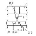
- rock structure which shows 1st Embodiment of this invention.
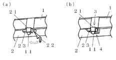
- the perspective view which shows before and after the engagement of the 2nd engaging part in the lock structure.
- Sectional drawing which shows before and after the engagement of the 2nd engaging part in the lock structure.
- the lock structure of the assembled part in the present invention is applied to, for example, a vehicle instrument.
- the vehicle instrument has an upper case 1 mainly made of a permeable resin and a lower case 2 made of a non-permeable or semi-permeable synthetic resin, and has a structure for storing and holding a circuit board, a dial plate, etc. (not shown). It has become.
- the upper case 1 and the lower case 2 are held by the first engagement portion 3, and then the second case is moved in a direction different from the engagement direction of the first engagement portion 3.
- the engaging portion 4 By engaging the engaging portion 4, the upper case 1 and the lower case 2 are firmly engaged and held.
- the first engaging portion 3 is engaged by engaging the first locking piece 11 formed integrally with the upper case 1 and the first engaging hole 21 formed integrally with the lower case 2. The match is complete.
- the first locking piece 11 has the space provided in the inner wall of the first engaging hole 21 facing the first locking piece 11 behind. Are engaged in a state where there is room to bend.
- the second engaging portion 4 includes a second locking piece 22 formed integrally with the first engaging hole 21 of the lower case 2 and a second locking piece sandwiching the first engaging hole 21. Engagement is completed by engaging the second engagement hole 23 arranged at the position 22.
- the second locking piece 22 has a thin portion 24 integrally formed with the first engagement hole 21, and the direction shown by the arrow in FIG. It becomes possible to engage and engage.
- the second locking piece 22 is provided on the inner wall of the first engagement hole 21 behind the first locking piece 11 when the second engaging portion 4 is engaged. It has the projection part 25 inserted in the space formed.
- the protrusion 25 When the protrusion 25 is disposed inside the first engagement hole 21, the protrusion 25 fills a space where the first locking piece 11 is pressed (or bends when an impact is applied). It is possible to prevent the first engagement portion 3 from coming off.
- the lock structure of the assembly component of the present invention includes the first locking piece 11 and the first engagement hole 21, and the first locking piece 11 engages with the first engagement hole 21.
- the first engaging portion 3 to be fixed, the second engaging piece 22 and the second engaging hole 23 are provided, and the second engaging piece 22 is the second engaging hole 23.
- the assembly lock structure provided with the second engagement portion 4 fixed by being engaged with the second engagement portion 4 the second engagement portion 4 is in a different direction from the first engagement portion 3. Since the two directions can be engaged by being engaged, a lock structure that is resistant to impacts is possible.
- the second locking piece 22 is integrally formed with the first engagement hole 21 and connected by the thin portion 24, so that a separate hinge part is provided.
- the second locking piece 22 can be made movable.
- the second locking piece 22 has a protrusion 25 that is inserted into the first engagement hole 21 when the second engagement portion is assembled. Accordingly, by removing the second engaging portion 4, the protruding portion 25 is detached from the first engaging hole 21, and the first locking piece 11 is bent in the space where the protruding portion 25 is inserted. Therefore, the first engaging portion 3 can be easily removed.
- the locking structure of the assembly component according to the present invention is not limited to this, and for example, for a vehicle A combination of a middle case and a lower case, or a turning member and an upper case is possible as long as it is an instrument, and it is applicable not only to a vehicle instrument but also to one that requires hook engagement.
- the present invention can be applied to a vehicle meter that displays vehicle information, and in particular, can be applied to a meter that does not easily disengage even when a load is applied to an assembled component.
Landscapes
- Engineering & Computer Science (AREA)
- General Engineering & Computer Science (AREA)
- Mechanical Engineering (AREA)
- Connection Of Plates (AREA)
Abstract
組み付け部品に負荷が加わっても係合が容易に外れない組み付け部品のロック構造を提供する。 第1の係止片11と第1の係合孔21を有し、第1の係止片11が第1の係合孔21に係合されることで固定される第1の係合部3と、第2の係止片22と第2の係合孔23を有し、第2の係止片22が第2の係合孔23に係合されることで固定される第2の係合部4と、を備えた組み付けロック構造において、第2の係合部4は、第1の係合部3とは、異なった方向に係合される。
Description
本発明は、組み付け部品のロック構造に関するもので、特に組み付け部品に負荷が加わっても係合が容易に外れない組み付け部品のロック構造に関するものである。
従来の組み付けロック構造は、係止用爪片5と、係止用爪片5を収容係止可能な爪孔部6とからなる爪係止部4を備えた上ケース2と、爪係止部4が係止される枠状突起14を備えた下ケース3とを、爪係止部4によって係止固定させるようにしたものが知られている。
しかしながら、このような組み付けロック構造は、落下の衝撃などにより係止用爪片5が内側に撓み、それによって爪係止部4が枠状突起14から外れてしまうという問題点があった。
そこで本発明は、第1の係止片と第1の係合孔を有し、前記第1の係止片が前記第1の係合孔に係合されることで固定される第1の係合部と、第2の係止片と第2の係合孔を有し、前記第2の係止片が前記第2の係合孔に係合されることで固定される第2の係合部と、を備えた組み付けロック構造において、
前記第2の係合部は、前記第1の係合部とは、異なった方向に係合されるものである。
前記第2の係合部は、前記第1の係合部とは、異なった方向に係合されるものである。
また本発明は、前記第2の係止片が、前記第1の係合孔と一体成型され、肉薄部によって連結されているものである。
また本発明は、前記第2の係止片は、前記第2の係合部を組み付けた際に、第1の係合孔に挿入される突起部を有しているものである。
本発明によれば、組み付け部品に負荷が加わっても係合が容易に外れない組み付け部品のロック構造を提供することができる。
以下、本発明の実施形態に係るロック構造を添付の図面を参照して具体的に説明する。
本願発明における組み付け部品のロック構造は、例えば車両用計器などに適用されるものである。車両用計器は、主に透過性樹脂からなる上ケース1と、不透過性もしくは半透過性の合成樹脂からなる下ケース2とを備え、図示しない回路基板や文字板などを収納保持する構造となっている。
図1に示すように、上ケース1と下ケース2とは、第1の係合部3によって保持され、その後、第1の係合部3の係合方向とは異なる方向に、第2の係合部4が係合されることによって、上ケース1と下ケース2とが強固に係合保持されるというものである。
第1の係合部3は、上ケース1に一体形成された第1の係止片11と、下ケース2に一体形成された第1の係合孔21とを係合することで、係合が完了する。第1の係合部3が係合された時点では、第1の係止片11は、第1の係合孔21の内壁に設けられた空間を第1の係止片11を背後に向けて撓ませる余裕がある状態で係合されている。
第2の係合部4は、下ケース2の第1の係合孔21と一体成形された第2の係止片22と、第1の係合孔21を挟んで第2の係止片22とする位置に配置された第2の係合孔23とを係合することで、係合が完了する。
第2の係止片22は、第1の係合孔21と一体成形された肉薄部24を有しており、この肉薄部24で折り曲げることで、図3(a)にて矢印で示す方向に移動し、係合可能となるものである。また、第2の係止片22には、第2の係合部4が係合される際に、第1の係合孔21の内壁であって第1の係止片11の背後に設けられた空間に挿入される突起部25を有している。
突起部25は、突起部25が第1の係合孔21の内側に配置されると、第1の係止片11が押される(または、衝撃が加わることによって撓む)空間を埋めるので、第1の係合部3が外れることを防ぐことができる。
このように本願発明の組み付け部品のロック構造は、第1の係止片11と第1の係合孔21を有し、第1の係止片11が第1の係合孔21に係合されることで固定される第1の係合部3と、第2の係止片22と第2の係合孔23を有し、第2の係止片22が第2の係合孔23に係合されることで固定される第2の係合部4と、を備えた組み付けロック構造において、第2の係合部4は、第1の係合部3とは、異なった方向に係合されることによって、2方向を係合することができるので、衝撃に強いロック構造が可能となる。
また、本願発明の組み付け部品のロック構造は、第2の係止片22が、第1の係合孔21と一体成型され、肉薄部24によって連結されていることによって、別途ヒンジ部品を設けることなく第2の係止片22を移動可能とすることができる。
また、本願発明の組み付け部品のロック構造は、第2の係止片22は、第2の係合部を組み付けた際に、第1の係合孔21に挿入される突起部25を有していることによって、第2の係合部4を外すことで突起部25が第1の係合孔21から外れ、突起部25が挿入されていた空間に第1の係止片11が撓むことが可能となり、第1の係合部3も容易に外すことができるロック構造となる。
なお、本実施形態では、上ケース1と下ケース2とを係合保持する場合を説明したが、本願発明に係る組み付け部品のロック構造は、これに限定されるものではなく、例えば、車両用計器であれば中ケースと下ケースや、見返し部材と上ケースといった組み合わせが可能であるし、車両用計器に限らず、フック係合が必要とされるものに適用できる。
本発明は、車両情報を表示する車両用メータに適用でき、特に、組み付け部品に負荷が加わっても係合が容易に外れないメータ等に適用可能である。
1 上ケース
2 下ケース
3 第1の係合部
4 第2の係合部
11 第1の係止片
21 第1の係合孔
22 第2の係止片
23 第2の係合孔
24 肉薄部
25 突起部
2 下ケース
3 第1の係合部
4 第2の係合部
11 第1の係止片
21 第1の係合孔
22 第2の係止片
23 第2の係合孔
24 肉薄部
25 突起部
Claims (3)
- 第1の係止片と第1の係合孔を有し、前記第1の係止片が前記第1の係合孔に係合されることで固定される第1の係合部と、第2の係止片と第2の係合孔を有し、前記第2の係止片が前記第2の係合孔に係合されることで固定される第2の係合部と、を備えた組み付けロック構造において、
前記第2の係合部は、前記第1の係合部とは、異なった方向に係合されることを特徴とする組み付け部品のロック構造。 - 前記第2の係止片が、前記第1の係合孔と一体成型され、肉薄部によって連結されていることを特徴とする請求項1に記載の組み付け部品のロック構造。
- 前記第2の係止片は、前記第2の係合部を組み付けた際に、前記第1の係合孔に挿入される突起部を有していることを特徴とする請求項1または2に記載の組み付け部品のロック構造。
Applications Claiming Priority (2)
| Application Number | Priority Date | Filing Date | Title |
|---|---|---|---|
| JP2012-239718 | 2012-10-31 | ||
| JP2012239718A JP2014088922A (ja) | 2012-10-31 | 2012-10-31 | 組み付け部品のロック構造 |
Publications (1)
| Publication Number | Publication Date |
|---|---|
| WO2014069158A1 true WO2014069158A1 (ja) | 2014-05-08 |
Family
ID=50627074
Family Applications (1)
| Application Number | Title | Priority Date | Filing Date |
|---|---|---|---|
| PCT/JP2013/077075 Ceased WO2014069158A1 (ja) | 2012-10-31 | 2013-10-04 | 組み付け部品のロック構造 |
Country Status (2)
| Country | Link |
|---|---|
| JP (1) | JP2014088922A (ja) |
| WO (1) | WO2014069158A1 (ja) |
Cited By (1)
| Publication number | Priority date | Publication date | Assignee | Title |
|---|---|---|---|---|
| CN108355240A (zh) * | 2018-03-06 | 2018-08-03 | 宁波越凡医疗科技有限公司 | 一种新型电刺激贴 |
Citations (4)
| Publication number | Priority date | Publication date | Assignee | Title |
|---|---|---|---|---|
| JPS5196178U (ja) * | 1975-01-30 | 1976-08-02 | ||
| JPS61118086U (ja) * | 1985-01-10 | 1986-07-25 | ||
| JPH0466412U (ja) * | 1990-10-23 | 1992-06-11 | ||
| JP2010242786A (ja) * | 2009-04-01 | 2010-10-28 | Toyota Motor Corp | 樹脂部品への部品取付け構造 |
-
2012
- 2012-10-31 JP JP2012239718A patent/JP2014088922A/ja active Pending
-
2013
- 2013-10-04 WO PCT/JP2013/077075 patent/WO2014069158A1/ja not_active Ceased
Patent Citations (4)
| Publication number | Priority date | Publication date | Assignee | Title |
|---|---|---|---|---|
| JPS5196178U (ja) * | 1975-01-30 | 1976-08-02 | ||
| JPS61118086U (ja) * | 1985-01-10 | 1986-07-25 | ||
| JPH0466412U (ja) * | 1990-10-23 | 1992-06-11 | ||
| JP2010242786A (ja) * | 2009-04-01 | 2010-10-28 | Toyota Motor Corp | 樹脂部品への部品取付け構造 |
Cited By (2)
| Publication number | Priority date | Publication date | Assignee | Title |
|---|---|---|---|---|
| CN108355240A (zh) * | 2018-03-06 | 2018-08-03 | 宁波越凡医疗科技有限公司 | 一种新型电刺激贴 |
| CN108355240B (zh) * | 2018-03-06 | 2023-12-29 | 宁波越凡医疗科技有限公司 | 一种新型电刺激贴 |
Also Published As
| Publication number | Publication date |
|---|---|
| JP2014088922A (ja) | 2014-05-15 |
Similar Documents
| Publication | Publication Date | Title |
|---|---|---|
| CN104662593B (zh) | 显示模块的保持结构 | |
| WO2014119366A1 (ja) | クリップの装着構造 | |
| JP4810521B2 (ja) | バンパ固定クリップ | |
| JP4299319B2 (ja) | コネクタ接続器のためのロック装置 | |
| JP5880973B2 (ja) | 電気接続箱 | |
| JP6002327B2 (ja) | 樹脂クリップ用補強板ばね | |
| JP6020925B2 (ja) | フラット回路体とコネクタとの接続構造 | |
| JP6162385B2 (ja) | 収納容器及び電子装置 | |
| JP2014088922A (ja) | 組み付け部品のロック構造 | |
| JP2009197900A (ja) | 二部材組付け構造 | |
| JP2014001825A (ja) | 部品の結合構造 | |
| JP5096967B2 (ja) | 車室内照明装置用ケース | |
| JP3186684U (ja) | 携帯型遠隔操作装置 | |
| JP4970341B2 (ja) | 二部材組付け構造 | |
| JP2011162129A (ja) | 車両用内装部品 | |
| CN204335223U (zh) | 盖构造 | |
| JP6180184B2 (ja) | フロント筐体固定構造 | |
| JP2016007971A (ja) | 部材の組付固定構造 | |
| WO2018198520A1 (ja) | ケース及び電子装置 | |
| JP5813817B1 (ja) | コネクタ及び電子機器 | |
| KR101325027B1 (ko) | 차량용 변속 케이블 고정장치 | |
| JP2009134048A (ja) | 表示装置 | |
| JP6281132B2 (ja) | アダプタ取付構造 | |
| JP6076154B2 (ja) | 計器ユニット | |
| JP2016124684A (ja) | エレベータ用の操作盤 |
Legal Events
| Date | Code | Title | Description |
|---|---|---|---|
| 121 | Ep: the epo has been informed by wipo that ep was designated in this application |
Ref document number: 13851818 Country of ref document: EP Kind code of ref document: A1 |
|
| NENP | Non-entry into the national phase |
Ref country code: DE |
|
| 122 | Ep: pct application non-entry in european phase |
Ref document number: 13851818 Country of ref document: EP Kind code of ref document: A1 |