WO2014068918A1 - 車両用電源装置 - Google Patents
車両用電源装置 Download PDFInfo
- Publication number
- WO2014068918A1 WO2014068918A1 PCT/JP2013/006295 JP2013006295W WO2014068918A1 WO 2014068918 A1 WO2014068918 A1 WO 2014068918A1 JP 2013006295 W JP2013006295 W JP 2013006295W WO 2014068918 A1 WO2014068918 A1 WO 2014068918A1
- Authority
- WO
- WIPO (PCT)
- Prior art keywords
- storage battery
- switch
- storage unit
- vehicle
- power storage
- Prior art date
- Legal status (The legal status is an assumption and is not a legal conclusion. Google has not performed a legal analysis and makes no representation as to the accuracy of the status listed.)
- Ceased
Links
Images
Classifications
-
- H—ELECTRICITY
- H01—ELECTRIC ELEMENTS
- H01M—PROCESSES OR MEANS, e.g. BATTERIES, FOR THE DIRECT CONVERSION OF CHEMICAL ENERGY INTO ELECTRICAL ENERGY
- H01M10/00—Secondary cells; Manufacture thereof
- H01M10/42—Methods or arrangements for servicing or maintenance of secondary cells or secondary half-cells
- H01M10/44—Methods for charging or discharging
- H01M10/441—Methods for charging or discharging for several batteries or cells simultaneously or sequentially
-
- B—PERFORMING OPERATIONS; TRANSPORTING
- B60—VEHICLES IN GENERAL
- B60L—PROPULSION OF ELECTRICALLY-PROPELLED VEHICLES; SUPPLYING ELECTRIC POWER FOR AUXILIARY EQUIPMENT OF ELECTRICALLY-PROPELLED VEHICLES; ELECTRODYNAMIC BRAKE SYSTEMS FOR VEHICLES IN GENERAL; MAGNETIC SUSPENSION OR LEVITATION FOR VEHICLES; MONITORING OPERATING VARIABLES OF ELECTRICALLY-PROPELLED VEHICLES; ELECTRIC SAFETY DEVICES FOR ELECTRICALLY-PROPELLED VEHICLES
- B60L50/00—Electric propulsion with power supplied within the vehicle
- B60L50/10—Electric propulsion with power supplied within the vehicle using propulsion power supplied by engine-driven generators, e.g. generators driven by combustion engines
-
- H—ELECTRICITY
- H01—ELECTRIC ELEMENTS
- H01M—PROCESSES OR MEANS, e.g. BATTERIES, FOR THE DIRECT CONVERSION OF CHEMICAL ENERGY INTO ELECTRICAL ENERGY
- H01M10/00—Secondary cells; Manufacture thereof
- H01M10/42—Methods or arrangements for servicing or maintenance of secondary cells or secondary half-cells
- H01M10/48—Accumulators combined with arrangements for measuring, testing or indicating the condition of cells, e.g. the level or density of the electrolyte
- H01M10/482—Accumulators combined with arrangements for measuring, testing or indicating the condition of cells, e.g. the level or density of the electrolyte for several batteries or cells simultaneously or sequentially
-
- H—ELECTRICITY
- H02—GENERATION; CONVERSION OR DISTRIBUTION OF ELECTRIC POWER
- H02J—ELECTRIC POWER NETWORKS; CIRCUIT ARRANGEMENTS OR SYSTEMS FOR SUPPLYING OR DISTRIBUTING ELECTRIC POWER; SYSTEMS FOR STORING ELECTRIC ENERGY
- H02J7/00—Circuit arrangements for charging or discharging batteries or for supplying loads from batteries
- H02J7/50—Circuit arrangements for charging or discharging batteries or for supplying loads from batteries acting upon multiple batteries simultaneously or sequentially
- H02J7/575—Parallel/serial switching of connection of batteries to charge or load circuit
-
- H—ELECTRICITY
- H01—ELECTRIC ELEMENTS
- H01M—PROCESSES OR MEANS, e.g. BATTERIES, FOR THE DIRECT CONVERSION OF CHEMICAL ENERGY INTO ELECTRICAL ENERGY
- H01M10/00—Secondary cells; Manufacture thereof
- H01M10/06—Lead-acid accumulators
-
- H—ELECTRICITY
- H01—ELECTRIC ELEMENTS
- H01M—PROCESSES OR MEANS, e.g. BATTERIES, FOR THE DIRECT CONVERSION OF CHEMICAL ENERGY INTO ELECTRICAL ENERGY
- H01M10/00—Secondary cells; Manufacture thereof
- H01M10/34—Gastight accumulators
- H01M10/345—Gastight metal hydride accumulators
-
- H—ELECTRICITY
- H01—ELECTRIC ELEMENTS
- H01M—PROCESSES OR MEANS, e.g. BATTERIES, FOR THE DIRECT CONVERSION OF CHEMICAL ENERGY INTO ELECTRICAL ENERGY
- H01M2220/00—Batteries for particular applications
- H01M2220/20—Batteries in motive systems, e.g. vehicle, ship, plane
-
- Y—GENERAL TAGGING OF NEW TECHNOLOGICAL DEVELOPMENTS; GENERAL TAGGING OF CROSS-SECTIONAL TECHNOLOGIES SPANNING OVER SEVERAL SECTIONS OF THE IPC; TECHNICAL SUBJECTS COVERED BY FORMER USPC CROSS-REFERENCE ART COLLECTIONS [XRACs] AND DIGESTS
- Y02—TECHNOLOGIES OR APPLICATIONS FOR MITIGATION OR ADAPTATION AGAINST CLIMATE CHANGE
- Y02E—REDUCTION OF GREENHOUSE GAS [GHG] EMISSIONS, RELATED TO ENERGY GENERATION, TRANSMISSION OR DISTRIBUTION
- Y02E60/00—Enabling technologies; Technologies with a potential or indirect contribution to GHG emissions mitigation
- Y02E60/10—Energy storage using batteries
-
- Y—GENERAL TAGGING OF NEW TECHNOLOGICAL DEVELOPMENTS; GENERAL TAGGING OF CROSS-SECTIONAL TECHNOLOGIES SPANNING OVER SEVERAL SECTIONS OF THE IPC; TECHNICAL SUBJECTS COVERED BY FORMER USPC CROSS-REFERENCE ART COLLECTIONS [XRACs] AND DIGESTS
- Y02—TECHNOLOGIES OR APPLICATIONS FOR MITIGATION OR ADAPTATION AGAINST CLIMATE CHANGE
- Y02T—CLIMATE CHANGE MITIGATION TECHNOLOGIES RELATED TO TRANSPORTATION
- Y02T10/00—Road transport of goods or passengers
- Y02T10/60—Other road transportation technologies with climate change mitigation effect
- Y02T10/70—Energy storage systems for electromobility, e.g. batteries
Definitions
- the present invention relates to a vehicle power supply device to be mounted on a vehicle.
- lead-acid batteries Electric power is supplied from the lead storage battery to the starter motor and various electrical components.
- lead acid batteries are inexpensive, they have a characteristic that their cycle life is short compared to nickel metal hydride batteries and lithium ion batteries. In vehicles having an idling stop function, the number of times of charging / discharging increases, so the life of the lead-acid battery is particularly short.
- the above-described switch may be turned off at a normal time due to a defect in wiring for transmitting the control signal. There may be a case where the malfunction of the switch cannot be recognized from the controller outputting the control signal.
- the present invention has been made in view of such circumstances, and an object of the present invention is to provide a technique for accurately detecting a malfunction of a switch inserted between power storage units connected in parallel to be mounted on a vehicle.
- the in-vehicle power supply device is mounted on a vehicle having an idling stop function and a deceleration energy regeneration function.
- the idling stop function is a function that automatically stops the engine when the vehicle stops and restarts the engine automatically when starting.
- the deceleration energy regeneration function is a function that generates power intensively at the time of deceleration when the engine is rotating due to inertia regardless of fuel. That is, during normal driving, the operation of the alternator is suppressed as much as possible to reduce the engine load. Both functions have the effect of improving fuel consumption.
- the number of engine starts increases in vehicles equipped with an idling stop function.
- the engine is usually started by a starter motor driven by battery voltage. Therefore, as the number of engine starts increases, the power consumption of the battery increases and the number of discharges increases.
- a vehicle equipped with a deceleration energy regeneration function is intensively activated during deceleration, a battery capable of efficient charging with a large capacity is required.
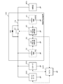
- FIG. 1 is a diagram for explaining an in-vehicle power supply device 100 according to an embodiment of the present invention.
- an alternator 200 In a vehicle on which the in-vehicle power supply device 100 is mounted, an alternator 200, a starter 300, an electrical component 400, and an ECU (Electronic Control Unit) 500 are mounted as members related to the in-vehicle power supply device 100.
- an alternator 200 In a vehicle on which the in-vehicle power supply device 100 is mounted, an alternator 200, a starter 300, an electrical component 400, and an ECU (Electronic Control Unit) 500 are mounted as members related to the in-vehicle power supply device 100.
- an alternator 200 In a vehicle on which the in-vehicle power supply device 100 is mounted, an alternator 200, a starter 300, an electrical component 400, and an ECU (Electronic Control Unit) 500 are mounted as members related to the in-vehicle power supply device 100.
- an alternator 200 In a vehicle on which
- the alternator 200 generates power by the rotational energy of the crankshaft of the engine (not shown). In the present embodiment, power is generated mainly during deceleration. The alternator 200 supplies the generated power to the in-vehicle power supply device 100.
- the starter 300 is an engine starting motor.
- the starter 300 is rotated by the electric power supplied from the in-vehicle power supply device 100 and starts the engine.
- an ignition switch (not shown) is turned on by the driver's operation, power is supplied from the in-vehicle power supply device 100 to the starter 300, and the starter 300 is started.
- the electrical component 400 is a generic name indicating various electric loads mounted in a vehicle such as a headlight, a power steering, an oil pump, a car navigation system, and an audio.
- a vehicle such as a headlight, a power steering, an oil pump, a car navigation system, and an audio.
- the alternator 200, the starter 300, and the ECU 500 are drawn separately from the electrical component 400.
- the electrical component 400 is driven by electric power supplied from the in-vehicle power supply device 100.
- ECU 500 is connected to various auxiliary devices, sensors, and switches mounted in the vehicle, and electronically controls the engine and various auxiliary devices.
- ECU 500 stops the engine when it detects stop of the vehicle or deceleration to a set speed or less based on a signal input from a brake, a vehicle speed sensor or the like. Further, ECU 500 restarts the engine when it detects that the brake is released. At that time, control is performed so that electric power is supplied from the in-vehicle power supply device 100 to the starter 300, and the starter 300 is operated.
- the ECU 500 When executing the deceleration energy regeneration function, the ECU 500 basically stops the alternator 200 during normal driving. ECU 500 activates alternator 200 when it detects deceleration of the vehicle based on signals input from a brake, a vehicle speed sensor or the like. When the capacity of the battery in in-vehicle power supply device 100 is lower than the set lower limit capacity, ECU 500 operates alternator 200 even during normal travel.
- a lead storage battery is used for the first storage battery 10 and a nickel hydride storage battery is used for the second storage battery 20.
- Lead storage batteries are relatively inexpensive, can operate in a relatively wide temperature range, and have advantages such as high output, and are widely used as storage batteries for vehicles.
- disadvantages such as low charge / discharge energy efficiency, weakness against overdischarge, and short cycle life.
- Nickel metal hydride storage batteries have advantages such as relatively high charge / discharge energy efficiency, resistance to overcharge and overdischarge, a wide use temperature range, a wide SOC (State (Of Charge) range, and a relatively long cycle life.
- SOC State
- there are disadvantages such as a large self-discharge, a memory effect, low voltage, and higher cost than a lead-acid battery.
- the first switch S1 is provided for voltage compensation so that the voltage of the path P1 does not drop below a predetermined voltage when the engine is cranked and restarted from the idling stop state.
- the above-described path P1 is designed to be 12V.
- Some electrical components 400 are reset when the voltage drops to about 10 V, such as a car navigation system.
- the starter 300 is operated, the potential of the charge / discharge terminal of the second storage battery 20 is stabilized by turning off the first switch S1, and a stable voltage can be continuously supplied to the electrical component 400.
- the diode D1 is provided in parallel with the first switch S1.
- the diode D1 is connected such that the cathode side is the second storage battery 20 side and the anode side is the first storage battery 10 side.
- Current flows from the alternator 200, the starter 300, and the first storage battery 10 side to the second storage battery 20 and the electrical component 400 side via the diode D1 in the state where the first switch S1 is off. It will not flow.
- the second storage battery control unit 40 manages and controls the second storage battery 20.
- the 2nd storage battery control part 40 is demonstrated more concretely.
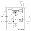
- FIG. 2 is a diagram for explaining the second storage battery control unit 40 of FIG. 1.
- the second storage battery control unit 40 includes a key input detection circuit 41, a high side switch 42, a constant voltage generation circuit 43, a battery state detection circuit 44, a communication interface 45, a CPU 46, a memory 47, and a switch control circuit 48.
- the constant voltage generation circuit 43 generates a power supply voltage for the CPU 46 and the switch control circuit 48.
- the 12V voltage of the path P1 is stepped down to a voltage of about 3 to 5V.
- a three-terminal regulator can be used for the constant voltage generation circuit 43.
- the battery state detection circuit 44 acquires the voltage, current, and temperature of the second storage battery 20.
- the second storage battery 20 is provided with a shunt resistor (not shown), and the current flowing through the second storage battery 20 can be detected by monitoring the voltage across the shunt resistor.
- the second storage battery 20 is provided with a thermistor (not shown), and the temperature of the second storage battery 20 can be detected.
- the battery state detection circuit 44 notifies the CPU 46 of the voltage, current, and temperature of the second storage battery 20.
- the communication interface 45 is an interface for communicating with the second storage battery control unit 40 and other control circuits (first storage battery control unit 30 and ECU 500 in the present embodiment).
- the communication interface 45 transmits information received from the outside to the CPU 46 and transmits information output from the CPU 46 to the outside.
- the communication interface 45 transmits the abnormality detection of the second storage battery 20 or the second storage battery control unit 40 to the ECU 500.
- the state information for example, voltage, current, temperature
- the state information of the second storage battery 20 is transmitted to the ECU 500.
- on / off information of the first switch S1 is transmitted to the ECU 500.
- a power generation request by the alternator 200 is transmitted to the ECU 500.
- the switch control circuit 48 switches the first switch S1 on / off in accordance with an instruction from the CPU 46.
- the first switch S1 is a relay
- the energization / non-energization of the relay coil is controlled.
- the first switch S1 is a semiconductor switching element
- the gate voltage is controlled.
- the first switch S1 is a relay, an open failure may occur. Even when the first switch S1 is a semiconductor switching element, current may not flow even when a specified gate voltage is applied due to malfunction. Further, the control of the first switch S1 by the CPU 46 may be disabled due to a failure of the switch control circuit 48, a disconnection between the switch control circuit 48 and the first switch S1, or the like.
- the power supply to the electrical component 400 is maintained because the second storage battery 20 is connected to the path P1. Even if the first switch S1 breaks down, the electrical component 400 or the second storage battery 20 does not immediately have a malfunction, and therefore the failure detection of the first switch S1 may be delayed. If the failure is left unattended, the second storage battery 20 is likely to be overdischarged. Moreover, the efficiency of the electric power supplied from the alternator 200 or the first storage battery 10 to the electrical component 400 is lowered by the forward voltage drop Vf of the diode D1.
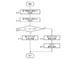
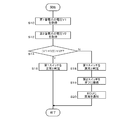
- FIG. 3 is a flowchart for explaining a failure determination process of the first switch S1 by the second storage battery control unit 40 according to the embodiment. This failure determination process is based on the premise that a signal for controlling the first switch S1 to be turned on is being supplied from the second storage battery control unit 40 to the first switch S1.
- the second storage battery control unit 40 acquires the voltage V1 of the first storage battery 10 from the first storage battery control unit 30 (S10). Moreover, the voltage V2 of the 2nd storage battery 20 is acquired. The second storage battery control unit 40 compares the differential voltage (V1-V2) with the forward drop voltage Vf of the diode D1 (S14). Since the on-resistance of the first switch S1 is negligible, when the first switch S1 is in the on state, the differential voltage (V1-V2) is substantially zero. On the other hand, when the first switch S1 is in the OFF state, the differential voltage (V1-V2) substantially matches the forward drop voltage Vf.
- step S14 when the differential voltage (V1-V2) and the forward voltage drop Vf substantially match (Y in S14), the second storage battery control unit 40 determines that the first switch S1 is normal (S16). When the differential voltage (V1-V2) and the forward voltage drop Vf do not substantially match (N in S14), the second storage battery control unit 40 determines that the first switch S1 or its control system is abnormal (S18), The abnormality is notified to ECU 500 (S20). Upon receiving the notification, ECU 500 performs stop control of alternator 200, alert notification to the driver, and the like.
- the failure determination process described above is basically executed when the second storage battery control unit 40 is activated. In addition, even after starting of the 2nd storage battery control part 40, you may perform regularly.
- the voltage of the first storage battery 10 was used as the terminal voltage on the anode side of the diode D1.
- the set output voltage value of the alternator 200 may be used, and when the DC-DC converter is provided at the subsequent stage of the alternator 200, the set output voltage value of the DC-DC converter may be used as it is.
- the failure of the first switch S1 inserted between the first storage battery 10 and the second storage battery 20 connected in parallel is detected by the diode D1 connected in parallel to the first switch S1.
- This can be accurately detected by using the forward voltage drop Vf. That is, the first switch S1 is turned on by comparing the difference between the voltage of the first storage battery 10 on the anode side of the diode D1 and the voltage of the second storage battery 20 on the cathode side and the forward drop voltage Vf of the diode D1. It is possible to accurately detect whether it is in the off state.
- the voltage detection circuit of the 1st storage battery 10 and the 2nd storage battery 20 can be diverted, it is not necessary to newly provide another voltage detection line. Therefore, the failure determination of the first switch S1 can be performed without increasing the cost.
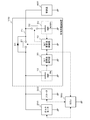
- the second switch S2 is provided to prevent overcharge and overdischarge of the second storage battery 20. Moreover, it has the effect
- a nickel metal hydride storage battery or a lithium ion storage battery has a lower internal resistance than a lead storage battery and a current easily flows, and thus is easily overcharged or overdischarged.
- FIG. 5 is a flowchart for explaining a failure determination process of the first switch S1 by the second storage battery control unit 40 according to the modification.
- the flowchart of FIG. 5 is obtained by adding the process of step S19 to the flowchart of FIG. In this failure determination process, it is assumed that a signal for controlling the first switch S1 to be turned on is supplied from the second storage battery control unit 40 to the first switch S1, and that the second switch S2 is in the on state. .
- the second storage battery control unit 40 determines that there is an abnormality in the first switch S1 or its control system (S18), in the modified example, the second switch S2 is controlled to be turned off (S19), and the abnormality is notified to the ECU 500 ( S20). Upon receiving the notification, ECU 500 performs stop control of alternator 200, alert notification to the driver, and the like. According to the modification, by turning off the second switch S2, it is possible to suppress the second storage battery 20 from being overdischarged before the first switch S1 is replaced or repaired.
- a fuse may be inserted between the path P1 and the second storage battery 20 described above.
- the second storage battery 20 can be protected from a large current.
Landscapes
- Engineering & Computer Science (AREA)
- General Chemical & Material Sciences (AREA)
- Manufacturing & Machinery (AREA)
- Chemical & Material Sciences (AREA)
- Chemical Kinetics & Catalysis (AREA)
- Electrochemistry (AREA)
- Power Engineering (AREA)
- Transportation (AREA)
- Mechanical Engineering (AREA)
- Charge And Discharge Circuits For Batteries Or The Like (AREA)
- Secondary Cells (AREA)
- Control Of Charge By Means Of Generators (AREA)
- Battery Mounting, Suspending (AREA)
Abstract
Description
Claims (4)
- 車両内の発電機により発電される電力を蓄え、エンジン始動用モータおよび車両内の電装品に給電するための第1蓄電部と、
前記第1蓄電部と並列に接続され、前記発電機により発電される電力を蓄え、車両内の電装品に給電するための第2蓄電部と、
前記第1蓄電部と前記第2蓄電部との間の経路に挿入されるスイッチと、
前記スイッチと並列に、カソード側が前記第2蓄電部側になるよう接続されるダイオードと、
前記スイッチを制御する制御部と、を備え、
前記制御部は、前記第1蓄電部の電圧、および前記第2蓄電部の電圧を監視し、それらの差分電圧と、前記ダイオードの順方向降下電圧を比較して、前記スイッチの異常を検出することを特徴とする車両用電源装置。 - 前記制御部は、前記経路に挿入されるスイッチの異常を検出すると、車両側の制御装置に、前記発電機から本車両用電源装置への電力供給を停止するよう指示することを特徴とする請求項1に記載の車両用電源装置。
- 前記経路と前記第2蓄電部との間に設けられる別のスイッチを、さらに備え、
前記制御部は、前記経路に挿入されるスイッチの異常を検出すると、前記別のスイッチをオフに制御することを特徴とする請求項1または2に記載の車両用電源装置。 - 前記第1蓄電部は鉛蓄電池を含み、前記第2蓄電部はニッケル水素蓄電池を含むことを特徴とする請求項1から3のいずれかに記載の車両用電源装置。
Priority Applications (2)
| Application Number | Priority Date | Filing Date | Title |
|---|---|---|---|
| US14/435,436 US9789769B2 (en) | 2012-10-29 | 2013-10-24 | Power supply device for vehicles |
| JP2014544262A JP6215221B2 (ja) | 2012-10-29 | 2013-10-24 | 車両用電源装置 |
Applications Claiming Priority (2)
| Application Number | Priority Date | Filing Date | Title |
|---|---|---|---|
| JP2012238301 | 2012-10-29 | ||
| JP2012-238301 | 2012-10-29 |
Publications (1)
| Publication Number | Publication Date |
|---|---|
| WO2014068918A1 true WO2014068918A1 (ja) | 2014-05-08 |
Family
ID=50626868
Family Applications (1)
| Application Number | Title | Priority Date | Filing Date |
|---|---|---|---|
| PCT/JP2013/006295 Ceased WO2014068918A1 (ja) | 2012-10-29 | 2013-10-24 | 車両用電源装置 |
Country Status (3)
| Country | Link |
|---|---|
| US (1) | US9789769B2 (ja) |
| JP (1) | JP6215221B2 (ja) |
| WO (1) | WO2014068918A1 (ja) |
Cited By (4)
| Publication number | Priority date | Publication date | Assignee | Title |
|---|---|---|---|---|
| EP2982536A1 (en) * | 2014-08-06 | 2016-02-10 | Toyota Jidosha Kabushiki Kaisha | Electric power supply device |
| JP2017131080A (ja) * | 2016-01-22 | 2017-07-27 | 株式会社Gsユアサ | バッテリ装置および二次電池の不正使用判断方法 |
| KR20180028239A (ko) * | 2016-09-08 | 2018-03-16 | 삼성에스디아이 주식회사 | 배터리 팩 |
| CN108377009A (zh) * | 2017-01-31 | 2018-08-07 | 丰田自动车株式会社 | 供电系统 |
Families Citing this family (14)
| Publication number | Priority date | Publication date | Assignee | Title |
|---|---|---|---|---|
| WO2014162885A1 (ja) * | 2013-04-05 | 2014-10-09 | 日産自動車株式会社 | 車両用電源装置 |
| JP2015209058A (ja) * | 2014-04-25 | 2015-11-24 | オムロンオートモーティブエレクトロニクス株式会社 | 電源装置 |
| JP2015217919A (ja) * | 2014-05-21 | 2015-12-07 | オムロンオートモーティブエレクトロニクス株式会社 | 車両用電源装置、車両用回生システム |
| JP2015217920A (ja) * | 2014-05-21 | 2015-12-07 | オムロンオートモーティブエレクトロニクス株式会社 | 車両用電源装置、車両用回生システム |
| DE102015107161A1 (de) * | 2015-05-07 | 2016-11-10 | Rwe Effizienz Gmbh | Verfahren und Vorrichtung zur Überprüfung einer Verbindung zwischen einem Elektrofahrzeug und einer Ladestation |
| KR101864564B1 (ko) * | 2015-05-22 | 2018-06-04 | 닛산 지도우샤 가부시키가이샤 | 전원 시스템 제어 장치 및 전원 시스템 제어 방법 |
| JP6551089B2 (ja) * | 2015-09-11 | 2019-07-31 | 株式会社オートネットワーク技術研究所 | 車載用電源装置 |
| JP6540565B2 (ja) * | 2016-03-16 | 2019-07-10 | 株式会社オートネットワーク技術研究所 | 車両用電源供給システム、車両用駆動システム |
| JP6494115B2 (ja) * | 2016-09-14 | 2019-04-03 | 本田技研工業株式会社 | 車両用電源装置 |
| CN110462969B (zh) * | 2017-03-31 | 2023-06-02 | 三洋电机株式会社 | 监视装置和蓄电系统 |
| WO2019059361A1 (ja) * | 2017-09-22 | 2019-03-28 | 株式会社デンソー | 車両電源システム、および電源制御装置 |
| JP6738847B2 (ja) * | 2018-03-13 | 2020-08-12 | 矢崎総業株式会社 | 車両用電源供給システム |
| JP7074725B2 (ja) * | 2019-07-18 | 2022-05-24 | 矢崎総業株式会社 | 電源システム、dcdcコンバータ装置、及び充電方法 |
| KR20220152826A (ko) * | 2021-05-10 | 2022-11-17 | 현대자동차주식회사 | 차량 전원 시스템 및 그 동작 방법 |
Citations (2)
| Publication number | Priority date | Publication date | Assignee | Title |
|---|---|---|---|---|
| JP2011176958A (ja) * | 2010-02-25 | 2011-09-08 | Denso Corp | 車載電源装置 |
| JP2012100438A (ja) * | 2010-11-02 | 2012-05-24 | Nec Energy Devices Ltd | 二次電池システム |
Family Cites Families (4)
| Publication number | Priority date | Publication date | Assignee | Title |
|---|---|---|---|---|
| US7765043B2 (en) * | 2003-05-12 | 2010-07-27 | Toyota Jidosha Kabushiki Kaisha | Power supply control apparatus and method |
| JP4277928B1 (ja) * | 2007-12-07 | 2009-06-10 | トヨタ自動車株式会社 | 車両 |
| JP5447260B2 (ja) * | 2010-02-11 | 2014-03-19 | 株式会社デンソー | 電池電圧監視装置 |
| CN102195333A (zh) * | 2010-03-17 | 2011-09-21 | 新神户电机株式会社 | 直流电源装置 |
-
2013
- 2013-10-24 JP JP2014544262A patent/JP6215221B2/ja active Active
- 2013-10-24 WO PCT/JP2013/006295 patent/WO2014068918A1/ja not_active Ceased
- 2013-10-24 US US14/435,436 patent/US9789769B2/en active Active
Patent Citations (2)
| Publication number | Priority date | Publication date | Assignee | Title |
|---|---|---|---|---|
| JP2011176958A (ja) * | 2010-02-25 | 2011-09-08 | Denso Corp | 車載電源装置 |
| JP2012100438A (ja) * | 2010-11-02 | 2012-05-24 | Nec Energy Devices Ltd | 二次電池システム |
Cited By (13)
| Publication number | Priority date | Publication date | Assignee | Title |
|---|---|---|---|---|
| US10155491B2 (en) | 2014-08-06 | 2018-12-18 | Toyota Jidosha Kabushiki Kaisha | Electric power supply device |
| KR20160017632A (ko) * | 2014-08-06 | 2016-02-16 | 도요타지도샤가부시키가이샤 | 전원 장치 |
| CN105365713A (zh) * | 2014-08-06 | 2016-03-02 | 丰田自动车株式会社 | 电源装置 |
| AU2015210407B2 (en) * | 2014-08-06 | 2016-09-01 | Toyota Jidosha Kabushiki Kaisha | Electric power supply device |
| RU2627234C2 (ru) * | 2014-08-06 | 2017-08-04 | Тойота Дзидося Кабусики Кайся | Устройство подачи электрической мощности |
| CN105365713B (zh) * | 2014-08-06 | 2018-07-06 | 丰田自动车株式会社 | 电源装置 |
| EP2982536A1 (en) * | 2014-08-06 | 2016-02-10 | Toyota Jidosha Kabushiki Kaisha | Electric power supply device |
| JP2017131080A (ja) * | 2016-01-22 | 2017-07-27 | 株式会社Gsユアサ | バッテリ装置および二次電池の不正使用判断方法 |
| KR20180028239A (ko) * | 2016-09-08 | 2018-03-16 | 삼성에스디아이 주식회사 | 배터리 팩 |
| KR102238607B1 (ko) * | 2016-09-08 | 2021-04-08 | 삼성에스디아이 주식회사 | 배터리 팩 |
| US10985580B2 (en) | 2016-09-08 | 2021-04-20 | Samsung Sdi Co., Ltd. | Battery pack |
| CN108377009A (zh) * | 2017-01-31 | 2018-08-07 | 丰田自动车株式会社 | 供电系统 |
| CN108377009B (zh) * | 2017-01-31 | 2021-08-20 | 丰田自动车株式会社 | 供电系统 |
Also Published As
| Publication number | Publication date |
|---|---|
| JP6215221B2 (ja) | 2017-10-18 |
| JPWO2014068918A1 (ja) | 2016-09-08 |
| US9789769B2 (en) | 2017-10-17 |
| US20150291039A1 (en) | 2015-10-15 |
Similar Documents
| Publication | Publication Date | Title |
|---|---|---|
| JP6215221B2 (ja) | 車両用電源装置 | |
| JP6312597B2 (ja) | 車両用電源装置 | |
| JP6367805B2 (ja) | 車両用電源システム | |
| JP6155569B2 (ja) | 電源システム | |
| JP6215220B2 (ja) | 車両用電源装置 | |
| JP5693788B2 (ja) | 自動車搭載電気システム、及び、自動車搭載電気システムの駆動方法 | |
| CN103171502B (zh) | 用于向车辆的电负载供电的供电系统 | |
| US11843274B2 (en) | Charge control apparatus for controlling charging of an energy storage device via purality of charging paths connected in parallel anssociated energy storage appartus, and an associated charging method | |
| US9856847B2 (en) | Vehicle power source device | |
| EP3170701B1 (en) | Vehicle power supply system | |
| CN110365098B (zh) | 供电装置 | |
| US9944188B2 (en) | On-board electrical system and method for operating an on-board electrical system | |
| JP2015204699A (ja) | 電池ユニット | |
| JPWO2014208028A1 (ja) | 蓄電システム | |
| JP2022093883A (ja) | 車載用のバックアップ制御装置及び車載用のバックアップ装置 | |
| JP2015009654A (ja) | 蓄電システム | |
| JP2008172908A (ja) | 車両用電源装置 | |
| JP6541414B2 (ja) | 電源供給装置 | |
| JP2015012685A (ja) | 蓄電システム | |
| JP7004385B2 (ja) | 管理装置、及び電源システム | |
| JP6165522B2 (ja) | 蓄電システム | |
| WO2021125193A1 (ja) | 車載電源装置の制御装置 | |
| JP2025007447A (ja) | 電源制御装置、電源制御方法、および電源制御プログラム |
Legal Events
| Date | Code | Title | Description |
|---|---|---|---|
| 121 | Ep: the epo has been informed by wipo that ep was designated in this application |
Ref document number: 13851146 Country of ref document: EP Kind code of ref document: A1 |
|
| WWE | Wipo information: entry into national phase |
Ref document number: 14435436 Country of ref document: US |
|
| ENP | Entry into the national phase |
Ref document number: 2014544262 Country of ref document: JP Kind code of ref document: A |
|
| NENP | Non-entry into the national phase |
Ref country code: DE |
|
| 122 | Ep: pct application non-entry in european phase |
Ref document number: 13851146 Country of ref document: EP Kind code of ref document: A1 |