WO2014065333A1 - イオン発生素子およびイオン発生装置 - Google Patents
イオン発生素子およびイオン発生装置 Download PDFInfo
- Publication number
- WO2014065333A1 WO2014065333A1 PCT/JP2013/078724 JP2013078724W WO2014065333A1 WO 2014065333 A1 WO2014065333 A1 WO 2014065333A1 JP 2013078724 W JP2013078724 W JP 2013078724W WO 2014065333 A1 WO2014065333 A1 WO 2014065333A1
- Authority
- WO
- WIPO (PCT)
- Prior art keywords
- electrode
- ion
- duct
- insulator
- tip
- Prior art date
- Legal status (The legal status is an assumption and is not a legal conclusion. Google has not performed a legal analysis and makes no representation as to the accuracy of the status listed.)
- Ceased
Links
Images








Classifications
-
- H—ELECTRICITY
- H01—ELECTRIC ELEMENTS
- H01T—SPARK GAPS; OVERVOLTAGE ARRESTERS USING SPARK GAPS; SPARKING PLUGS; CORONA DEVICES; GENERATING IONS TO BE INTRODUCED INTO NON-ENCLOSED GASES
- H01T19/00—Devices providing for corona discharge
- H01T19/04—Devices providing for corona discharge having pointed electrodes
-
- H—ELECTRICITY
- H01—ELECTRIC ELEMENTS
- H01T—SPARK GAPS; OVERVOLTAGE ARRESTERS USING SPARK GAPS; SPARKING PLUGS; CORONA DEVICES; GENERATING IONS TO BE INTRODUCED INTO NON-ENCLOSED GASES
- H01T23/00—Apparatus for generating ions to be introduced into non-enclosed gases, e.g. into the atmosphere
Definitions
- the present invention relates to an ion generation element and an ion generation apparatus, and more particularly to an ion generation element and an ion generation apparatus that generate ions by discharge.
- an ion generating element using a discharge phenomenon it is known that a sharp portion of an electrode for generating discharge is consumed due to discharge. With respect to the consumption of the electrode, it is possible to reduce the consumption of the electrode by appropriately selecting the shape, material, discharge intensity and the like of the electrode. Thus, it is considered possible to configure the electrode so that it can withstand actual use.
- Japanese Patent Application Laid-Open No. 2006-210311 is a technique that takes into account the wear due to discharge.
- the ion generator disclosed in this publication has a needle electrode to which a high voltage is applied, and a ground electrode having leg portions located on both sides in the radial direction of the needle electrode. It is described in the above publication that this configuration stabilizes the amount of ion generation because the wire diameter of the needle electrode does not change with time.
- the tip of the needle-like electrode may be gradually consumed due to discharge due to long-term use. In that case, the influence of ion generation on the performance gradually appears.
- the sensing level is brought closer to normal, the difference is small and difficult to distinguish, and there is a risk of misjudgment. Is also envisaged.
- the present invention has been made in view of the above-described problems, and an object of the present invention is to provide an ion generating element that has a simple configuration and that controls the period in which ion performance gradually decreases due to electrode consumption due to discharge, and to a minimum.
- An ion generator is provided.
- the ion generating element of the present invention includes a support portion, a first electrode, and a first insulator.
- the support portion has an opening that forms at least a part of the air passage.
- the first electrode is supported by the support portion so as to protrude into the opening portion, and has a first tip portion located in the opening portion.
- the first insulator exposes the first tip portion of the first electrode and is a portion on the support portion side of the first tip portion of the first electrode portion protruding from the support portion into the opening. It is formed in close contact with the outer periphery of.
- the first insulator is formed in close contact with the outer periphery of the portion of the first electrode closer to the support portion than the first tip portion. For this reason, the discharge by the first electrode can be stopped when the first electrode is consumed from the first tip portion to the insulator by the discharge generated at the first electrode. Therefore, by adjusting the length of the portion from the first tip portion of the first electrode to the first insulator, etc., it is possible to minimize the period during which the ion performance gradually deteriorates due to electrode consumption due to discharge. It becomes possible to control to. In addition, the above-described control of the ion performance degradation period can be easily performed with a simple configuration in which an insulator is brought into close contact with the outer periphery of the first electrode.
- the first insulator by bringing the first insulator into close contact with the outer periphery of the first electrode, it is possible to prevent a gap from being generated between the first insulator and the first electrode. As a result, it is possible to prevent a weak discharge generated in the gap, and it is possible to more accurately stop the discharge within a specified time.
- the above ion generating element further includes a second electrode and a second insulator.
- the second electrode is supported by the support portion so as to protrude into the opening portion, and has a second tip portion located in the opening portion.
- the second insulator exposes the second tip portion of the second electrode, and of the portion of the second electrode that protrudes from the support portion into the opening, the portion closer to the support portion than the second tip portion It is formed in close contact with the outer periphery of.
- Both the first and second electrodes have a needle shape.
- both the first and second electrodes are consumed, so that both the first and second electrodes are controlled to minimize the period during which the ion performance gradually decreases due to electrode consumption due to discharge. It becomes possible.
- both the first and second electrodes have a needle shape, an electric field distribution can be created in a wider space than when the electrodes are formed in a plate shape or a ring shape.
- ions generated in the vicinity of the discharge electrode side of the first and second electrodes are moved to the induction electrode side of the first and second electrodes. Can be less absorbed. As a result, ions can be generated efficiently.
- the second electrode is located on an extension line in the extending direction of the first electrode, and the second tip is opposed to the first tip in the opening.
- the second electrode is disposed on the extended line of the first electrode, and the tip portion of the first electrode and the tip portion of the second electrode are opposed to each other.
- the tip portions of the first and second electrodes are gradually consumed by the discharge, and the distance between the tip portions is increased to stop the discharge.
- the above-described ion generating element further includes a second electrode that is supported by the support portion and has a portion exposed in the opening.
- the first electrode is a needle electrode
- the second electrode is an electrode having a flat plate portion exposed from the support portion.
- the first insulator includes a portion integral with the support portion. Thereby, the number of parts of an ion generating element can be reduced.
- the length of the portion of the first electrode exposed from the first insulator from the first insulator to the first tip is the length of the first electrode from the support portion. It is 1/2 or less of the length of the part protruded from the support part to 1 front-end
- the portion exposed from the insulator of the first electrode can be separated from the support portion by a predetermined distance. For this reason, it can suppress that the ion produced by the discharge in a 1st electrode is absorbed by a support part.
- the first electrode is consumed by the discharge generated in the first electrode, so that the portion from the first tip portion of the first electrode to the first insulator is consumed and discharge occurs. Is configured to stop.
- An ion generating apparatus includes any one of the above-described ion generating elements, a detection unit for detecting the presence or absence of discharge generated in the ion generation element, and an electrode in response to a result of determining that there is no discharge in the detection unit. And a display unit for displaying replacement.
- the ion generating apparatus of the present invention since the above-described ion generating element is provided, it is possible to control the period during which the ion performance gradually decreases due to the consumption of the electrode due to the discharge with a simple configuration to the minimum. An ion generator can be obtained. Moreover, since the display of electrode replacement appears on the display unit, the user can replace the electrode at an appropriate time.
- an ion generating element and an ion generating apparatus that have a simple configuration and that controls the period during which the ion performance gradually decreases due to the consumption of the electrode due to discharge.
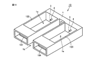
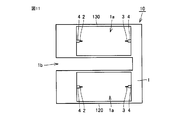
- FIG. 8 is a cross-sectional view as seen from the direction of arrows VIII-VIII in FIG. It is sectional drawing seen from the IX-IX line arrow direction of FIG. It is a perspective view which shows the external appearance of the ion generating element which concerns on the ion generator of FIG. It is a top view which shows the external appearance of the ion generating element which concerns on the ion generator of FIG.
- ion generating element 10 of the present embodiment mainly has a frame (supporting portion) 1, a first electrode 2, a second electrode 3, and an insulator 4. ing.
- the frame body 1 is formed with a through hole (opening) 1a at the center thereof. This through hole 1a constitutes at least a part of the air passage.
- the first electrode 2 is supported by the frame 1 so as to protrude into the through hole 1a, and has a tip 2a located in the through hole 1a.
- the second electrode 3 is supported by the frame 1 so as to protrude into the through hole 1a, and has a distal end portion 3a positioned in the through hole 1a.
- Both the first and second electrodes 2 and 3 have a needle shape.
- Each of the front end portions 2a and 3a of the first and second electrodes 2 and 3 may have a needle shape with a sharp point, or may not have a sharp point.
- the first and second electrodes 2 and 3 extend from the joint portion with the frame body 1 to the tip portions 2a and 3a while maintaining substantially the same diameter. It has a cylindrical shape with a minute diameter.
- the second electrode 3 is located on an extension line (the one-dot chain line AA in the figure) in the extending direction of the first electrode 2, and the tip portion 3a is opposed to the tip portion 2a in the through hole 1a. ing. That is, the first and second electrodes 2 and 3 are arranged on a straight line along a virtual straight line AA.
- the extension line AA of the first electrode 2 is preferably the center line of the through hole 1a.
- the center line AA of the through hole 1a is a bisector that bisects the through hole 1a when the through hole 1a is viewed from directly above the through direction of the through hole 1a as shown in FIG. .
- An insulator 4 is formed on the outer periphery of the first electrode 2.
- the insulator 4 has a tip portion 2a out of the portion of the first electrode 2 protruding from the frame 1 into the through hole 1a so that the tip portion 2a of the first electrode 2 is exposed to the through hole 1a. Is also formed in close contact with the outer periphery of the frame 1 side portion.
- an insulator 4 is also formed on the outer periphery of the second electrode 3.
- the insulator 4 has a tip 3a out of the portion of the second electrode 3 protruding from the frame 1 into the through hole 1a so that the tip 3a of the second electrode 3 is exposed in the through hole 1a. Is also formed in close contact with the outer periphery of the frame 1 side portion.
- the insulator 4 is preferably in close contact with the entire outer circumference of each of the first and second electrodes 2 and 3. However, if the discharge can be stopped when the consumption due to the discharge of the first and second electrodes 2 and 3 reaches the insulator 4, a part of the outer periphery rather than the entire periphery of the first and second electrodes 2 and 3. It may be formed so as to be in close contact only with the angle range ⁇ (0 ° ⁇ ⁇ 360 °).
- the length L1a of the portion of the first electrode 2 exposed from the insulator 4 from the insulator 4 to the tip 2a protrudes from the frame 1 from the frame 1 to the tip 2a of the first electrode 2. It is preferable that it is 1/2 or less of the length L1b of the part.
- the length L2a of the portion of the second electrode 3 exposed from the insulator 4 from the insulator 4 to the tip portion 3a is the length L2a of the second electrode 3 from the frame body 1 from the frame body 1 to the tip portion 3a. It is preferable that it is 1/2 or less of the length L2b of the protruding portion.
- the distance (interelectrode distance) D between the tip 2a of the first electrode 2 and the tip 3a of the second electrode 3 is preferably 15 mm or more and 200 mm or less. As will be described later, the interelectrode distance D is particularly preferably 80 mm.
- Each of the diameters of the first and second electrodes 2 and 3 is preferably 0.1 mm or more and 0.4 mm or less.
- tip parts 2a and 3a of the 1st and 2nd electrodes 2 and 3 may be a needle-like pointed tip, and does not need to be pointed.
- a power supply circuit unit 11 is electrically connected to the first electrode 2 and the second electrode 3.
- a positive or negative high voltage is applied to one of the first and second electrodes 2 and 3, and for example, a zero potential is applied to the other.
- the electrode to which the high voltage is applied becomes the discharge electrode, and the electrode to which the zero potential is applied becomes the induction electrode.
- the first and second electrodes 2 and 3 are consumed by the discharge generated in the first and second electrodes 2 and 3, so that the portion from the tip 2 a of the first electrode 2 to the insulator 4 is removed. Or the portion from the distal end portion 3a of the second electrode 3 to the insulator 4 is consumed and the discharge is stopped.
- the insulator 4 includes the first and second insulators. It may be formed only on the outer periphery of one of the electrodes 2 and 3.
- second electrode 3 is an electrode having a flat plate portion exposed from frame body 1, and hardly protrudes from frame body 1.
- the insulator 4 is not formed on the outer periphery of the second electrode 3.
- the first electrode 2 is disposed along a virtual straight line AA
- the second electrode 3 is a virtual straight line different from the straight line AA.
- the straight line AA and the straight line BB are parallel to each other, for example.
- the second electrode 3 is not arranged along the virtual straight line AA.
- the second electrode 3 is an electrode having a flat plate portion exposed from the frame 1, and hardly protrudes from the frame 1.
- the insulator 4 is not formed on the outer periphery of the second electrode 3.
- the second electrode 3 may be a needle electrode in which the insulator 4 is not formed on the outer periphery. In this case, the entire portion of the second electrode 3 protruding from the frame 1 is exposed to the through hole 1a.
- the angle formed by the straight line AA and the straight line BB may be any of a right angle, an acute angle, and an obtuse angle.
- the insulator 4 may be made of a material different from that of the frame 1, or may be made of the same material. Moreover, the insulator 4 may be comprised separately from the frame 1, and may be formed integrally. Further, when the insulator 4 is configured integrally with the frame 1, the entire insulator 4 may be configured integrally with the frame 1, and as shown in FIGS. 5 and 6, the insulator 4 Only a part of 4 may be configured integrally with the frame 1, and the remaining part may be configured separately from the frame 1.
- insulator 4 includes a first insulator portion 4a and a second insulator portion 4b.
- the first insulator portion 4 a is configured integrally with the frame body 1 and is made of the same material as the frame body 1.
- the first insulator portion 4 a is formed so as to be in close contact with the outer periphery of the electrode 2 or the electrode 3.
- the second insulator portion 4b is formed so as to cover the outer peripheral surface and the tip end surface of the first insulator portion 4a.
- the insulator 4 has a first insulator portion 4a and a second insulator portion 4b.
- the first insulator portion 4 a is configured integrally with the frame body 1 and is made of the same material as the frame body 1.
- the first insulator portion 4 a is formed so as to be in close contact with the outer periphery of the electrode 2 or the electrode 3.
- the second insulator portion 4b is formed so as to cover the outer peripheral surface of the first insulator portion 4a and not to cover the front end surface of the first insulator portion 4a.
- a space 5 or a casing 5 serving as an air blowing path may be disposed between the second insulator portion 4 b and the frame body 1.
- the frame body 1 and the first insulator portion 4 a are integrally formed of a molding material, so that the first insulator portion 4 a is formed by the first electrode 2 or the first electrode 2. 2 can be brought into close contact with the outer peripheral surface of the electrode 3.
- the first insulator portion 4a is formed of a molding material
- the second insulator portion 4b and the portion of the electrodes 2 and 3 that start to protrude from the frame 1 (the base) are sealed with a sealing member.
- the frame 1 and the first insulator portion 4a may be formed by injecting liquid rubber instead of the molding material by the above method. Also in this case, the first insulator portion 4 a made of cured rubber can be brought into close contact with the outer peripheral surface of the first electrode 2 or the second electrode 3.
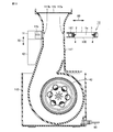
- ion generation apparatus 100 includes ion generation element 10, ion sensor (detection unit) 101, housing 110, and first and second ducts 117 and 118. And the blowing cylinders 113 and 114 and the air blowing mechanism (the impellers 40 and 41 and the motor 30).
- the casing 110 has an upper casing 111 and a lower casing 112 that are combined with each other, and has a substantially rectangular parallelepiped shape.
- the upper housing 111 and the lower housing 112 are engaged with each other by a snap fit member and are detachably combined.
- the upper casing 111 has two fitting holes in the upper part.
- the blowing cylinder 113 is detachably fitted in one of the two fitting holes.
- the blowing cylinder 114 is detachably fitted into the other fitting hole of the two fitting holes.
- the blowing cylinders 113 and 114 have a tapered outer shape in the longitudinal section.
- the upper end of the blowing cylinder 113 is the outlet 113a.
- a protective net 115 is arranged so as to cover the lower end of the blowing cylinder 113.
- the upper end of the blowout cylinder 114 is the blowout outlet 114a.
- a protective net 116 is arranged so as to cover the lower end of the blowing cylinder 114.
- the protective nets 115 and 116 are provided to prevent foreign objects such as fingers from being inserted from the outside.
- the lower housing 112 has two suction ports 112a and 112b on the side.
- An impeller 40 is disposed in the lower housing 112 so as to face one of the suction ports 112a.
- An impeller 41 is disposed in the lower housing 112 so as to face the other suction port 112b.
- the impellers 40 and 41 are multi-blade impellers having a plurality of blades whose rotational center side is displaced in the rotation direction with respect to the outer edge.
- the impellers 40 and 41 are cylindrical sirocco impellers.
- the impellers 40 and 41 have a bearing plate at one end. A shaft hole is provided in the center of the bearing plate. The output shaft of the motor 30 is attached to this shaft hole.
- the impellers 40 and 41 have through holes on the surfaces facing the suction ports 112a and 112b.
- the impellers 40 and 41 are configured so that a gas such as air sucked from the through hole into the central cavity is discharged from between the blades of the outer peripheral portion.
- the impellers 40 and 41 and the motor 30 constitute a blower mechanism.
- the ion generator 100 In order to distribute separately the gas discharged from the impeller 40 and the gas discharged from the impeller 41, the ion generator 100 has two flow paths.
- the first flow path is a flow path of the gas sucked from the suction port 112a and released from the impeller 40, and is constituted by the first duct 117. That is, the first duct 117 constitutes a first flow path through which a part of the gas blown by the blower mechanism flows.
- the upper part of the first duct 117 has a cylindrical outer shape that is rectangular in plan view and extends in the vertical direction.
- the lower portion of the first duct 117 has a cylindrical outer shape that is substantially circular in a side view and surrounds the periphery of the impeller 40 along the outer shape of the impeller 40.
- the first duct 117 has an opening facing the lower end of the blowing cylinder 113 at the upper end.
- a protection net 115 is attached to the upper end of the first duct 117 so as to close the opening.
- the opening at the upper end of the first duct 117 is completely covered by the protective net 115.
- the second flow path is a flow path for the gas sucked from the suction port 112b and discharged from the impeller 41, and is constituted by the second duct 118. That is, the 2nd duct 118 comprises the 2nd flow path through which the remainder of the gas ventilated by the ventilation mechanism distribute
- the second duct 118 is located adjacent to the first duct 117.
- the upper part of the second duct 118 has a cylindrical outer shape that is rectangular in plan view and extends in the vertical direction.
- the lower part of the second duct 118 has a cylindrical outer shape that is substantially circular in a side view so as to surround the periphery of the impeller 41 along the outer shape of the impeller 41.
- the second duct 118 has an opening at the upper end facing the lower end of the blowing cylinder 114.
- a protection net 116 is attached to the upper end of the second duct 118 so as to close the opening.
- the opening at the upper end of the second duct 118 is completely covered by the protective net 116.
- the ion generator 100 has the ion generating element 10 that is detachably attached to the first duct 117 and the second duct 118.
- Ion generation element 10 includes, for example, positive ion generation unit 120 and negative ion generation unit 130.
- ion generating element 10 mainly includes frame (supporting portion) 1, first electrode 2, second electrode 3, and insulator 4. .
- Two through holes (openings) 1a are formed in the frame 1.
- Each of the two through holes 1a constitutes at least a part of the air passage.
- One of the two through holes 1a corresponds to the positive ion generator 120, and the other corresponds to the negative ion generator 130.
- the first electrode 2 is supported by the frame body 1 so as to protrude into the through hole 1a, and has a tip portion positioned in the through hole 1a.
- the second electrode 3 is supported by the frame body 1 so as to protrude into the through hole 1a, and has a tip portion located in the through hole 1a.
- the second electrode 3 is located on an extension line in the direction in which the first electrode 2 extends, and the tip is opposed to the tip in the through hole 1a. That is, the first and second electrodes 2 and 3 are arranged on a straight line along a virtual straight line.
- An insulator 4 is formed on the outer periphery of the first electrode 2.
- the insulator 4 exposes the tip of the first electrode 2 and is a portion of the first electrode 2 that protrudes from the frame 1 into the through hole 1a and is closer to the frame 1 than the tip. It is formed in close contact with the outer periphery.
- an insulator 4 is also formed on the outer periphery of the second electrode 3.
- This insulator 4 exposes the tip of the second electrode 3 and is a portion of the portion of the second electrode 3 protruding from the frame 1 into the through hole 1a on the frame 1 side of the tip. It is formed in close contact with the outer periphery.
- Each first electrode 2 is arranged so that the extension line of the first electrode 2 in the positive ion generation unit 120 and the extension line of the first electrode 2 in the negative ion generation unit 130 are parallel to each other.
- the through-hole 1a of the rectangular parallelepiped positive ion generator 120 and the through-hole 1a of the rectangular parallelepiped negative ion generator 130 are arranged in parallel.
- a predetermined gap 1 b is provided between the through hole 1 a of the positive ion generator 120 and the through hole 1 a of the negative ion generator 130.
- the skeleton of the ion generating element 10 is composed of a frame 1 made of a resin molded product.
- the first electrode 2 of the positive ion generator 120 is provided so as to penetrate the first electrode substrate 141.
- the front end portion of the first electrode 2 protruding to one main surface side of the first electrode substrate 141 passes through the frame body 1 and is located in the opening 1a.
- the base portion of the first electrode 2 protruding to the other main surface side of the first electrode substrate 141 is electrically connected to the first connector 184 provided on the other main surface of the first electrode substrate 141. ing.
- the first electrode substrate 141 and the first connector 184 are accommodated in the cavity at the other end of the frame body 1.
- the first electrode 2 of the negative ion generator 130 is provided so as to penetrate the second electrode substrate 171.
- the front end portion of the first electrode 2 protruding to one main surface side of the second electrode substrate 171 passes through the frame body 1 and is located in the opening 1a.
- the base portion of the first electrode 2 protruding to the other main surface side of the second electrode substrate 171 is electrically connected to the second connector 187 provided on the other main surface of the second electrode substrate 171. ing.
- the second electrode substrate 171 and the second connector 187 are accommodated in the cavity at the other end of the frame 1.
- Each of the second electrode 3 of the positive ion generator 120 and the second electrode 3 of the negative ion generator 130 is provided so as to penetrate the third electrode substrate 151.
- a conductive pattern (not shown) is provided on the main surface of the third electrode substrate 151.
- the second electrode 3 of the positive ion generator 120 and the second electrode 3 of the negative ion generator 130 are connected to each other by a conductive pattern and have the same potential.
- the conductive pattern is electrically connected to the third connector 152 provided on the main surface of the third electrode substrate 151.
- the third electrode substrate 151 and the third connector 152 are accommodated in a cavity at one end of the frame 1.
- the tip of the third connector 152 faces the gap 1 b provided in the frame body 1.
- the power supply circuit unit 11 and the control unit 12 are provided in the upper casing 111 on the sides of the first duct 117 and the second duct 118.
- the control unit 12 includes a control board and a power supply unit (not shown). As shown in FIG. 8, the power supply unit is connected to an AC (alternating current) cord 90 that is pulled out from the lower portion of the lower casing 112 and connected to a commercial power supply, and can supply an alternating current.
- the control unit 12 is fixed to the first duct 117 and the second duct 118.
- the power supply circuit unit 11 is electrically connected to the ion generating element 10, thereby applying a positive voltage to the first electrode 2 of the positive ion generating unit 120 and the first electrode 2 of the negative ion generating unit 130. A negative voltage can be applied.
- the power supply circuit unit 11 can apply a zero potential to each second electrode 3 of the positive ion generator 120 and the negative ion generator 130.
- the first electrode 2 of each of the positive ion generator 120 and the negative ion generator 130 corresponds to the discharge electrode
- the second electrode 3 of each of the positive ion generator 120 and the negative ion generator 130 is inductive. Corresponds to the electrode.
- power supply circuit unit 11 has a first terminal 11 a connected to first connector 184 and a second terminal 11 b connected to second connector 187.
- a positive voltage can be applied from the power supply circuit unit 11 to the first electrode 2 of the positive ion generator 120 via the first terminal 11 a and the first connector 184.
- a negative voltage can be applied from the power supply circuit unit 11 to the second electrode 2 of the negative ion generator 130 via the second terminal 11b and the second connector 187.
- the power supply circuit unit 11 has a third terminal 153 connected to the secondary winding of the step-up transformer 17 (FIG. 14).
- the third terminal 153 is electrically connected to the third connector 152 by a conducting wire 185.
- the first connector 184 and the first terminal 11a, the second connector 187 and the second terminal 11b, and the third connector 152 and the third terminal 153 are detachably connected to each other. Thereby, the ion generating element 10 is detachably attached to the first duct 117 and the second duct 118.
- the ion generating element 10 can be attached to and detached from the first duct 117 and the second duct 118 in a state where the upper casing 111 is removed from the lower casing 112.
- a first opening 117 a for attaching and detaching the ion generating element 10 is provided in the upper wall portion of the first duct 117.
- an opening 117b for attaching / detaching the ion generating element 10 is provided in a position facing the first opening 117a in the upper wall portion of the first duct 117.
- a second opening (not shown) for attaching and detaching the ion generating element 10 is provided in the upper wall portion of the second duct 118 so as to extend continuously from the first opening 117a.
- an opening for attaching and detaching the ion generating element 10 is provided in the upper wall portion of the second duct 118 at a position facing the second opening.
- the ion generating element 10 can be attached to and detached from the first duct 117 and the second duct 118 by moving the ion generating element 10 in the direction indicated by the arrow 60 with respect to the first duct 117 and the second duct 118. .
- first and second electrodes 2 and 3 are located away from each other at both ends in the cross section of the first flow path. Note that the first and second electrodes 2 and 3 of the negative ion generator 130 do not necessarily have to be located at both ends in the cross section of the first flow path, as long as they are located at least in the first flow path. Good.
- the positive ion generator 120 is inserted into the second opening, and the first and second electrodes 2 and 3 of the positive ion generator 120 are located away from each other at both ends in the cross section of the second flow path. Yes.
- the first and second electrodes 2 and 3 of the positive ion generator 120 do not necessarily have to be located at both ends in the cross section of the second flow path, as long as they are located at least in the second flow path. Good.
- the positive ion generating part 120 and the negative ion generating part 130 can be arranged in separate flow paths.
- a part of the first flow path can be configured by the through hole 1 a of the negative ion generation unit 130.
- a part of the second flow path can be constituted by the through-hole 1a of the positive ion generator 120.
- the power supply circuit unit 11 is detachably connected to the control unit 12 by being moved in the direction indicated by the arrow 70. That is, the power supply circuit unit 11 is detachably attached to the first duct 117 and the second duct 118. Specifically, each of the power supply circuit unit 11 and the control unit 12 has a terminal portion that is detachably engaged with each other.
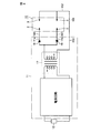
- a power supply circuit is configured by connecting the ion generating element 10, the power supply circuit unit 11, and the control unit 12 to each other.
- the power supply circuit unit 11 has a step-up transformer 17. Further, the power supply circuit unit 11 has a power supply circuit connected between the primary side of the step-up transformer 17 and the power supply unit of the control unit 12.
- a diode 18 and a diode 19 are connected in parallel to the secondary side of the step-up transformer 17. From the secondary side of the step-up transformer 17, a step-up AC voltage obtained by boosting the commercial AC voltage is output from the diode 18 and the diode 19.
- the cathode terminal of the diode 18 is electrically connected to the first electrode 2 of the positive ion generator 120.
- the positive voltage of the step-up AC voltage output from the secondary side of the step-up transformer 17 can be applied to the first electrode 2 of the positive ion generator 120.
- the anode terminal of the diode 19 is electrically connected to the first electrode 2 of the negative ion generator 130.
- the negative voltage of the step-up AC voltage output from the secondary side of the step-up transformer 17 can be applied to the first electrode 2 of the negative ion generator 130.
- a voltage on the secondary side of the step-up transformer 17 can be applied to each of the second electrodes 3 of the positive ion generator 120 and the negative ion generator 130.
- corona discharge occurs between the first and second electrodes 2 and 3 of the positive ion generation unit 120 to generate positive ions. Further, corona discharge occurs between the first and second electrodes 2 and 3 of the negative ion generator 130 to generate negative ions.
- the potential difference between the first and second electrodes 2 and 3 of the positive ion generator 120 and between the first and second electrodes 2 and 3 of the negative ion generator 130 may be 3 kV or more and 10 kV or less. preferable. When the potential difference is smaller than 3 kV, corona discharge is difficult to occur and ions cannot be generated sufficiently. When the potential difference is greater than 10 kV, there is a high possibility that arc discharge will occur, and the ion generator 100 may fail.
- the potential of the second electrode 3 of each of the positive ion generation unit 120 and the negative ion generation unit 130 is set to 0 potential.
- the zero potential means that the second electrode 3 of each of the positive ion generator and the negative ion generator is grounded, or the second electrode 3 of each of the positive ion generator 120 and the negative ion generator 130 is grounded.
- This is a potential obtained by electrically floating, and includes around 0V and 0V.
- the second electrode 3 of each of the positive ion generation unit 120 and the negative ion generation unit 130 is connected by the third connector 152, the third terminal 153, and the conducting wire 185, and is at zero potential. I have to. Thereby, the electric potential of each 2nd electrode 3 of the positive ion generation part 120 and the negative ion generation part 130 can be stabilized, and the discharge in the positive ion generation part 120 and the negative ion generation part 130 can be stabilized.
- the release of positive ions and the release of negative ions are performed alternately every half cycle of the boosted AC voltage.
- an AC power supply is used in this embodiment, a DC power supply may be used.
- the gas sucked from the suction port 112a as shown by the arrow 210 in FIG. 7 is blown by the blower mechanism as shown by the arrow 210a.
- the air flows upward through the first flow path, passes through the negative ion generator 130, and is blown out from the outlet 113a as indicated by an arrow 210b.
- the negative ions generated between the first and second electrodes 2 and 3 of the negative ion generation unit are released from the air outlet 113a by a part of the gas blown by the blower mechanism.
- the gas sucked from the suction port 112b as shown by the arrow 220 in FIG. 7 is blown by the blower mechanism as shown by the arrow 220a and the second flow path. It rises inside, passes through the positive ion generator 120, and is blown out from the outlet 114a as indicated by an arrow 220b.
- positive ions generated between the first and second electrodes 2 and 3 of the positive ion generation unit are released from the outlet 114a by the remaining part of the gas blown by the blower mechanism.
- ion sensor 101 is arranged on the downstream side of each of positive ion generation unit 120 and negative ion generation unit 130, between positive ion generation unit 120 and air outlet 114 a, and negative ions. It arrange
- the ion sensor 101 is installed on the wall surfaces of the first and second ducts 117 and 118. The ion sensor 101 is for detecting the presence or absence of discharge generated in the ion generation element 10 (positive ion generation unit 120, negative ion generation unit 130).
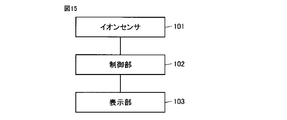
- a control unit 102 is electrically connected to the ion sensor 101, and a display unit 103 is electrically connected to the control unit 102.
- the control unit 102 determines whether or not there is a discharge from the detection result of the ion sensor 101 and outputs a signal based on the determination result. Specifically, when the output of the ion sensor 101 is equal to or lower than a predetermined value, the control unit 102 reduces the amount of generated ions to be lower than a specified value (this state is expressed as “discharge stopped”). Judge.
- the display unit 103 is for displaying an electrode exchange in response to a result determined by the control unit 102 that there is no discharge.
- the display unit 103 is disposed outside the housing 110 so as to be in contact with the user's eyes, and includes, for example, a blinkable lamp.
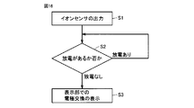
- the ion sensor 101 detects the presence or absence of discharge generated in the ion generation element 10 (positive ion generation unit 120, negative ion generation unit 130) (step S1).
- a detection signal from the ion sensor 101 is input to the control unit 102.
- the control unit 102 determines whether or not the ion generating element 10 (positive ion generating unit 120, negative ion generating unit 130) has been discharged (step S2).
- step S2 determines that a discharge has occurred
- step S3 the determination by the controller 102 based on the detection signal from the ion sensor 101
- step S3 the display unit 103 displays electrode replacement based on the signal output from the control unit 102. Specifically, the lamp (not shown) of the display unit 103 is blinked to prompt the user to replace the electrode unit. In this way, display of electrode replacement on the display unit 103 is performed.
- the ion generating element 10 shown in FIG. 1 has been described as the ion generating element 10 shown in FIGS. 7 to 13, any one of the types shown in FIGS. 2 to 4 may be used as the ion generating element 10.
- the insulator 4 is formed in close contact with the outer periphery of the portion of the first electrode 2 closer to the frame body 1 than the distal end portion 2a.
- the insulator 4 is formed in close contact with the outer periphery of the portion of the second electrode 3 closer to the frame body 1 than the distal end portion 3a.
- the discharge by the first electrode 2 can be stopped when the first electrode 2 is consumed from the tip 2 a to the insulator 4 by the discharge generated in the first electrode 2.
- the discharge by the second electrode 3 can also be stopped by the second electrode 3 being consumed from the tip 3 a to the insulator 4 by the discharge generated by the second electrode 3.
- the length of the portion from the tip portion 2a of the first electrode 2 to the insulator 4 is adjusted by adjusting the length of the portion from the tip portion 2a of the first electrode 2 to the insulator 4, the length of the portion of the second electrode 3 from the tip portion 3a to the insulator 4, and the like, It is possible to control to a minimum the period during which the ion performance gradually decreases due to electrode consumption.
- the above-described ease of controlling the ion performance degradation period can be realized with a simple configuration in which the insulator 4 is brought into close contact with the outer periphery of the first or second electrode 2 or 3.
- both the first and second electrodes 2 and 3 have ion performance due to electrode consumption due to discharge. It is possible to control the period of gradual decrease to a minimum.
- the number of parts of the ion generating element 10 can be reduced because the insulator 4 includes a portion integral with the frame 1.
- the second electrode 3 is disposed on the extension line AA of the first electrode 2, and the tip 2a of the first electrode 2 and the tip 3a of the second electrode 3 are opposed to each other. ing.
- both the first and second electrodes 2 and 3 are consumed due to the discharge generated between the first and second electrodes 2 and 3, thereby increasing the distance between the tip portions 2 a and 3 a.
- each of the first and second electrodes 2 and 3 is arranged along the center line AA of the through hole 1a, it is easy to make the ion distribution uniform with respect to the air path. Since the first and second electrodes 2 and 3 are arranged along the center line AA of the through hole 1a, the first and second electrodes 2 and 3 are offset from the center line AA. The ions are less likely to be taken into the air channel wall surface than in the case where they are arranged.
- both the first and second electrodes 2 and 3 have a needle shape. For this reason, compared with the case where an electrode is formed in plate shape or ring shape, a strong electric field can be concentrated between electrodes which oppose. Therefore, it is possible to increase the distance D between the first electrode 2 and the second electrode 3 while suppressing an increase in applied voltage necessary for discharge. Thereby, compared with the case where the distance D between the first electrode 2 and the second electrode 3 is small, ions generated in the vicinity of the first electrode 2 (for example, the discharge electrode) are moved to the second electrode 3 side. It can be made difficult to be absorbed by (for example, the induction electrode side).
- the diameter of the first electrode 2 is 0.1 mm or more and 0.4 mm or less. Thereby, the balance between the time required for the consumption of the first electrode 2 and the influence on the performance of ion generation can be improved.
- the distance D between the first electrode 2 and the second electrode 3 is preferably 15 mm or more and 200 mm or less.
- the interelectrode distance D is less than 15 mm, arc discharge is likely to occur, and ozone gas may be generated at a high concentration.
- the proportion of ions generated in the vicinity of the first electrode 2 is absorbed by the second electrode 3 increases. That is, the ion generation efficiency decreases.
- the distance between the electrodes is larger than 200 mm, corona discharge is likely to occur not between the first electrode 2 and the second electrode 3 but between another object existing near the electrode and the electrode. For example, corona discharge may occur between the inner wall of the frame 1 and the first electrode 2 existing near the second electrode 3, and the ion generation efficiency may decrease.
- the length L1a of the portion of the first electrode 2 exposed from the insulator 4 from the insulator 4 to the tip 2a is the length L1a of the first electrode 2 from the frame 1 to the tip 2a. It is 1/2 or less of the length L1b of the part protruded from the frame 1 until.
- the length L2a of the portion of the second electrode 3 exposed from the insulator 4 from the insulator 4 to the tip portion 3a is the length L2a of the second electrode 3 from the frame body 1 from the frame body 1 to the tip portion 3a. It is 1/2 or less of the length L2b of the protruding portion.
- the exposed portions of the first and second electrodes 2 and 3 from the insulator 4 can be separated from the frame 1 by a predetermined distance. For this reason, it is possible to suppress the ions generated by the discharge at the first and second electrodes 2 and 3 from being absorbed by the frame body 1.
- the user can replace the electrode at an appropriate time. It can be performed. That is, according to the ion generating apparatus 100 of the present embodiment, it is possible to realize a structure in which the discharge performance is maintained for a certain time and the discharge stops thereafter, and if the end of the discharge is detected, the electrode is provided to the user. Can be used in a state where good performance is always obtained.
- positive ions and negative ions are H + (H 2 O) m (m is an arbitrary natural number) and negative ions are O 2 ⁇ (H 2 O) n (n is an arbitrary natural number), positive ions and negative ions are It attaches to the surface of airborne bacteria to generate active species such as hydrogen peroxide (H 2 O 2 ) or hydroxyl radical (.OH), and a bactericidal effect can be obtained by its action.
- active species such as hydrogen peroxide (H 2 O 2 ) or hydroxyl radical (.OH)
- the ion generator 100 when the discharge electrode deteriorates with the passage of time of use, the ion generating element 10 can be removed from the power supply circuit unit 11 and easily replaced. Further, when the power supply circuit unit 11 is deteriorated, the power supply circuit unit 11 can be removed from the control unit 12 and easily replaced.
- Example 1 As shown in FIGS. 17 and 18, air was blown into a common duct 900 having a flow path having a length of 604 mm and a width of 34 mm by a cross flow fan (not shown) at a flow rate of 5 m / sec on the electrode.
- an interval of 20 mm is placed between the first duct 217 having a flow path having a length of 103 mm and a width of 34 mm in the upper center of the common duct 900 and the first duct 217.
- the second duct 218 having a flow path having a length of 103 mm and a width of 34 mm was provided.
- the distance between the outer wall of the first duct 217 and the outer wall of the second duct 218 that are positioned opposite to each other and facing each other was 245 mm.
- the first needle-like electrode 240 protruding 11.5 mm from the inner wall of the first duct 217 opposite to the second duct 218 side was provided.
- a second needle-like electrode 250 projecting 11.5 mm was provided so as to face the first needle-like electrode 240 from the inner wall of the first duct 217 on the second duct 218 side.
- the distance between the tip of the first needle electrode 240 and the tip of the second needle electrode 250 was 80 mm.
- the first needle-like electrode 270 protruding 11.5 mm from the inner wall of the second duct 218 opposite to the first duct 217 side was provided.
- a second needle electrode 260 protruding 11.5 mm was provided so as to face the first needle electrode 270 from the inner wall of the second duct 218 on the first duct 217 side.
- the distance between the tip of the first needle electrode 270 and the tip of the second needle electrode 260 was 80 mm.
- the first needle-like electrode 240 and the second needle-like electrode 250 in the first duct 217 are connected as shown in FIG.
- the first duct 217 is positioned so as to be biased to one side in the path direction (width direction).
- the central axes of the first acicular electrode 240 and the second acicular electrode 250 are positioned at a position 8 mm from one end in the path direction between the one end and the other end of the first duct 217.
- the first acicular electrode 240 and the second acicular electrode 250 were arranged.
- first needle-like electrode 270 and the second needle-like electrode 260 in the second duct 218 were positioned so as to be biased toward one side in the path direction (width direction) of the second duct 218.
- the central axes of the first needle-like electrode 270 and the second needle-like electrode 260 are located at a position 8 mm from one end in the path direction between the one end and the other end of the second duct 218.
- the first acicular electrode 270 and the second acicular electrode 260 were arranged.
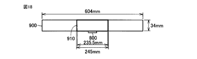
- a duct 910 having a channel having a length of 235.5 mm and a width of 34 mm is provided at the upper center of the common duct 900. Air was blown into the common duct 900 at a flow rate of 5 m / sec on the electrode by a cross flow fan (not shown). The ion generating part 800 was arranged on the inner wall on one side in the width direction of the duct 910.
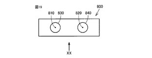
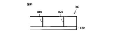
- the ion generation unit 800 includes a first needle electrode 810 and a second needle electrode 820 that protrude from the power supply circuit unit 850 (FIG. 20).
- the first and second needle-like electrodes 810 and 820 are located in parallel with a space therebetween.
- the ion generator 800 has a predetermined distance from the tip of the first needle electrode 810 and the tip of the second needle electrode 820 and the annular first induction electrode 830 facing the tip of the first needle electrode 810. And an annular second induction electrode 840 facing each other.
- the ion generator 800 is arranged so that the tips of the first needle electrode 810 and the second needle electrode 820 are in contact with the flow path in the duct 910.
- the power supply circuit unit 850 applies a positive high voltage to the first needle electrode 810 and a negative high voltage to the second needle electrode 820, so that the first induction electrode 830 and the second induction electrode 840 are applied.
- positive ions were generated from the vicinity of the tip of the first needle electrode 810 and negative ions were generated from the vicinity of the tip of the second needle electrode 820.
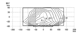
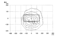
- FIG. 21 is a graph showing the concentration distribution of positive ions measured at a position 250 mm away from the electrode above the first duct 217 and the second duct 218 in the reference example shown in FIG.
- FIG. 22 is a graph showing the concentration distribution of positive ions measured at a position 1 m away from the electrode above the first duct 217 and the second duct 218 in the reference example.
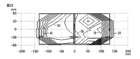
- FIG. 23 is a graph showing the negative ion concentration distribution measured at a position 250 mm away from the electrode above the first duct 217 and the second duct 218 in the reference example shown in FIG.
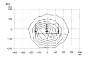
- FIG. 24 is a graph showing the negative ion concentration distribution measured at a position 1 m away from the electrode above the first duct 217 and the second duct 218 in the reference example.
- FIG. 25 is a graph showing the concentration distribution of positive ions measured at a position 250 mm away from the electrode above the duct 910 in the comparative example shown in FIGS.
- FIG. 26 is a graph showing the concentration distribution of positive ions measured at a position 1 m away from the electrode above the duct 910 in the comparative example.
- FIG. 27 is a graph showing the concentration distribution of negative ions measured at a position 250 mm away from the electrode above the duct 910 in the comparative example shown in FIGS.
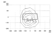
- FIG. 28 is a graph showing the negative ion concentration distribution measured at a position 1 m away from the electrode above the duct 910 in the comparative example.
- the vertical axis indicates the duct width direction coordinate
- the horizontal axis indicates the duct length direction coordinate
- the normalized ion concentration is indicated by contour lines.
- the center position of the flow path in the common duct 900 is set to 0 on the coordinate axis.
- a high concentration region of positive ions exists on the first needle electrode 240 side on the first duct 217 at a position 250 mm away from the electrode in the reference example.
- a high concentration region of negative ions exists on the first needle electrode 270 side on the second duct 218. Therefore, most of the positive ions and the negative ions are located away from each other immediately after the release, and the bond annihilation of the positive ions and the negative ions is suppressed.
- positive ions are diffused radially from substantially the center of the common duct 900 at a position 1 m away from the electrode.
- negative ions are diffused radially from substantially the center of the common duct 900. Therefore, positive ions and negative ions are mixed in a wide area of the released space.
- positive ions are diffused radially from substantially the center of the duct 910 at a position 1 m away from the electrode.
- negative ions are diffused radially from substantially the center of the duct 910 at a position 1 m away from the electrode. Therefore, positive ions and negative ions are mixed in the released space.
- concentration of released positive ions and negative ions was lower than that of the reference example, and the range of released positive ions and negative ions was also narrower than that of the reference example.
- Example 2 Using the ion generator of the comparative example (FIG. 17) and the ion generators of the reference examples (FIGS. 18 to 20) used in Experimental Example 1, the amount of ions at a position 500 mm from the electrode was compared. The amount of ions was measured at a total of 35 points in a lattice shape of 5 points at 25 mm intervals in the width direction of the common duct 900 and 7 points at 50 mm intervals in the length direction.
- Table 1 summarizes the maximum value of the positive ion amount, the maximum value of the negative ion amount, and the integrated value of the ion amount at the 35 measurement points among the 35 measurement points in the comparative example and the reference example. is there.
- the maximum value of the positive ion amount in the comparative example was 4.2 nA
- the maximum value of the negative ion amount was 3.9 nA
- the integrated value of the ion amount at 35 measurement points was 39.9 nA.
- the maximum positive ion amount in the reference example is 5.4 nA, 129% of the comparative example, the maximum negative ion amount is 5.1 nA, 131% of the comparative example, and the integrated value of the ion amount at 35 measurement points is 94.1 nA. It was 236% of the comparative example.
- the ion generator of the reference example was able to supply more positive ions and negative ions than the ion generator of the comparative example. Moreover, it was confirmed that many ions can be supplied by setting the distance between electrodes to 80 mm.
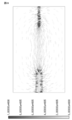
- Example 3 As shown in FIG. 1, the electric field vector generated in the through hole 1 a when the first and second electrodes 2 and 3 are arranged along the center line of the through hole 1 a of the frame 1 was examined.
- the length, width, and height of the through-hole 1a were set to 50 mm, 30 mm, and 30 mm, respectively, and the diameters ( ⁇ ) of the first and second electrodes were set to 0.4 mm.
- the length of each of the first and second electrodes was 11.75 mm. As a result, a result as shown in FIG. 29 was obtained.
- the present invention can be widely applied to a high voltage generation circuit, an ion generation device including an ion generation element, a portable electric device, a battery-driven ion generation device, and the like.
Landscapes
- Disinfection, Sterilisation Or Deodorisation Of Air (AREA)
- Physics & Mathematics (AREA)
- Engineering & Computer Science (AREA)
- Plasma & Fusion (AREA)
Abstract
第1の電極(2)は、貫通孔(1a)内に突き出すように枠体(1)に支持され、かつ貫通孔(1a)内に位置する先端部(2a)を有している。第2の電極(3)は、貫通孔(1a)内に突き出すように枠体(1)に支持され、かつ貫通孔(1a)内に位置する先端部(3a)を有している。絶縁体(4)は、第1および第2の電極(2、3)の各々の先端部(2a、3a)を露出し、かつ枠体(1)から貫通孔(1a)内に突き出した第1および第2の電極(2、3)の各々の部分のうち先端部(2a、3a)よりも枠体(1)側の部分の外周に密着して形成されている。
Description
本発明は、イオン発生素子およびイオン発生装置に関し、特に、放電によりイオンを生成するイオン発生素子およびイオン発生装置に関するものである。
放電現象を利用したイオン発生素子において、特に放電を生じさせるための電極の先鋭部が放電により消耗することが知られている。この電極の消耗に対しては、電極の形状、材質、放電の強さなどを適切に選ぶことにより電極の消耗を低減することができる。これにより、電極を実際の使用に耐えられるように構成することは可能であると考えられる。
放電による消耗を考慮した技術として、たとえば特開2006-210311号公報(特許文献1参照)がある。この公報に開示されたイオン発生装置は、高電圧を印加される針状電極と、針状電極の径方向の両側に位置する脚部を有するグランド電極とを有している。この構成により、経時変化で針状電極の線径が変化しないためイオン発生量が安定することが上記公報に記載されている。
しかしながら上記公報に記載のイオン発生装置においても、長期の使用により、針状電極の先端部が放電により徐々に消耗する場合があり得る。その場合には、イオン発生の性能への影響も徐々に出てくる。徐々に性能に影響が出始めイオンセンシングするレベルに到達するまでの期間はできる限り少ない時間にしたいが、センシングレベルを正常時に近づけていくとその差が小さく、見分けがつきにくく、誤判定の懸念も想定される。
本発明は、上記の課題に鑑みてなされたものであり、その目的は、簡易な構成で放電による電極の消耗でイオン性能が徐々に低下していく期間を最小限に制御したイオン発生素子およびイオン発生装置を提供することである。
本発明のイオン発生素子は、支持部と、第1の電極と、第1の絶縁体とを備えている。支持部は、風路の少なくとも一部を構成する開口部を有している。第1の電極は、開口部内に突き出すように支持部に支持され、かつ開口部内に位置する第1の先端部を有している。第1の絶縁体は、第1の電極の第1の先端部を露出し、かつ支持部から開口部内に突き出した第1の電極の部分のうち第1の先端部よりも支持部側の部分の外周に密着して形成されている。
本発明のイオン発生素子によれば、第1の絶縁体が第1の電極のうち第1の先端部よりも支持部側の部分の外周に密着して形成されている。このため第1の電極が、第1の電極で生じる放電により第1の先端部から絶縁体まで消耗することにより、第1の電極による放電を停止させることができる。よって、第1の電極の第1の先端部から第1の絶縁体までの部分の長さなどを調整することで、放電による電極の消耗でイオン性能が徐々に低下していく期間を最小限に制御することが可能となる。また上記のイオン性能低下期間の制御の容易化を、第1の電極の外周に絶縁体を密着させるという簡易な構成で実現することができる。
また第1の絶縁体を第1の電極の外周に密着させることにより、第1の絶縁体と第1の電極との間に隙間が生じることが防止される。これにより、その隙間で発生する微弱な放電も防止することができ、より的確に規定時間内で放電を停止させることが可能となる。
上記のイオン発生素子は、第2の電極と、第2の絶縁体とをさらに備えている。第2の電極は、開口部内に突き出すように支持部に支持され、かつ開口部内に位置する第2の先端部を有している。第2の絶縁体は、第2の電極の第2の先端部を露出し、かつ支持部から開口部内に突き出した第2の電極の部分のうち第2の先端部よりも支持部側の部分の外周に密着して形成されている。第1および第2の電極の双方は針状形状を有している。
これにより第1および第2の電極の双方が消耗することで、第1および第2の電極の双方で、放電による電極の消耗でイオン性能が徐々に低下していく期間を最小限に制御することが可能となる。
また第1および第2の電極の双方が針状形状を有しているため、電極を板状またはリング状に形成する場合に比べて、広い空間に電界分布を作ることができ、第1の電極と第2の電極との間の距離が小さい場合に比べて、第1および第2の電極のうち放電電極側の近傍で発生したイオンを第1および第2の電極のうち誘導電極側に吸収されにくくすることができる。その結果、イオンを効率よく発生させることができる。
上記のイオン発生素子において、第2の電極は第1の電極の延びる方向の延長線上に位置し、かつ第2の先端部は開口部内で第1の先端部と離れて対向している。
また第1の電極の延長線上に第2の電極が配置され、かつ第1の電極の先端部と第2の電極の先端部とが互いに離れて対向している。長期の使用により、第1および第2の電極の先端部が放電により徐々に消耗し、先端部の距離が拡大して放電が停止するように構成されている。このような構成とすることで、先端部の間隔などを調整することにより、放電による電極の消耗でイオン性能が徐々に低下していく期間を最小限に制御することができる。
上記のイオン発生素子は、支持部に支持され、かつ開口部内に露出する部分を有する第2の電極をさらに備えている。記第1の電極は針状電極であり、第2の電極は支持部から露出した平板部を有する電極である。
上記のイオン発生素子において、第1の絶縁体は支持部と一体の部分を含んでいる。
これにより、イオン発生素子の部品点数を削減することができる。
これにより、イオン発生素子の部品点数を削減することができる。
上記のイオン発生素子において、第1の電極のうち第1の絶縁体から第1の先端部までの第1の絶縁体から露出する部分の長さは、第1の電極のうち支持部から第1の先端部までの支持部から突き出した部分の長さの1/2以下である。
これにより、第1の電極の絶縁体から露出した部分を支持部から所定距離だけ離すことができる。このため、第1の電極での放電で生じたイオンが支持部に吸収されることを抑制することができる。
上記のイオン発生素子において、第1の電極は、第1の電極で生じる放電により消耗することで第1の電極の第1の先端部から第1の絶縁体までの部分が消耗して放電が停止するように構成されている。
これにより、第1の電極のうち第1の先端部から第1の絶縁体までの部分の長さなどを調整することでイオン発生性能の維持される期間を容易に制御することができる。
本発明のイオン発生装置は、上記いずれかのイオン発生素子と、そのイオン発生素子で生じる放電の有無を検出するための検出部と、その検出部で放電が無いと判断した結果を受けて電極交換の表示を行う表示部とを備えている。
本発明のイオン発生装置によれば、上記のイオン発生素子が備えられているため、簡易な構成で、放電による電極の消耗でイオン性能が徐々に低下していく期間を最小限に制御可能なイオン発生装置を得ることができる。また表示部に電極交換の表示が出るため、使用者は適切な時期に電極の交換を行うことができる。
つまり一定時間までは放電性能を持続させ、それ以降は放電が止まってしまう構造が実現でき、その放電の終了を検出すれば、使用者に電極の交換を知らせ、常に良い性能が得られる状態で使ってもらうことができる。
以上説明したように本発明によれば、簡易な構成で放電による電極の消耗でイオン性能が徐々に低下していく期間を最小限に制御したイオン発生素子およびイオン発生装置を得ることができる。
まず、本発明の一実施の形態におけるイオン発生素子の構成について図1~図6を用いて説明する。
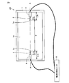
図1を参照して、本実施の形態のイオン発生素子10は、枠体(支持部)1と、第1の電極2と、第2の電極3と、絶縁体4とを主に有している。枠体1には、その中央部分に貫通孔(開口部)1aが形成されている。この貫通孔1aは、風路の少なくとも一部を構成している。
第1の電極2は、貫通孔1a内に突き出すように枠体1に支持され、かつ貫通孔1a内に位置する先端部2aを有している。第2の電極3は、貫通孔1a内に突き出すように枠体1に支持され、かつ貫通孔1a内に位置する先端部3aを有している。
第1および第2の電極2、3の双方は針状形状を有している。第1および第2の電極2、3の先端部2a、3aの各々は、先が尖った針状となっていてもよく、また先が尖っていなくてもよい。第1および第2の電極2、3の各々は、先が尖っていない場合には、実質的に同一の径を維持しながら枠体1との接合部から先端部2a、3aまで延びた、微小な径の円柱形状を有している。
第2の電極3は第1の電極2の延びる方向の延長線(図中の一点鎖線A-A)上に位置し、かつ先端部3aは貫通孔1a内で先端部2aと離れて対向している。つまり第1および第2の電極2、3は仮想の直線A-Aに沿って一直線上に配置されている。
この第1の電極2の延長線A-Aは貫通孔1aの中心線であることが好ましい。貫通孔1aの中心線A-Aとは、図1に示すように貫通孔1aの貫通方向真上から貫通孔1aを見たときに、貫通孔1aを二等分する二等分線である。
第1の電極2の外周には絶縁体4が形成されている。この絶縁体4は、第1の電極2の先端部2aを貫通孔1aに露出するように、かつ枠体1から貫通孔1a内に突き出した第1の電極2の部分のうち先端部2aよりも枠体1側の部分の外周に密着するように形成されている。
同様に、第2の電極3の外周にも絶縁体4が形成されている。この絶縁体4は、第2の電極3の先端部3aを貫通孔1aに露出するように、かつ枠体1から貫通孔1a内に突き出した第2の電極3の部分のうち先端部3aよりも枠体1側の部分の外周に密着するように形成されている。
絶縁体4は第1および第2の電極2、3の各々の外周の全周上に密着していることが好ましい。しかし、第1および第2の電極2、3の放電による消耗が絶縁体4に達した時点で放電が停止できれば第1および第2の電極2、3の外周の全周ではなく外周の一部の角度範囲θ(0°<θ<360°)だけに密着するように形成されていてもよい。
第1の電極2のうち絶縁体4から先端部2aまでの絶縁体4から露出する部分の長さL1aは、第1の電極2のうち枠体1から先端部2aまでの枠体1から突き出した部分の長さL1bの1/2以下であることが好ましい。また第2の電極3のうち絶縁体4から先端部3aまでの絶縁体4から露出する部分の長さL2aは、第2の電極3のうち枠体1から先端部3aまでの枠体1から突き出した部分の長さL2bの1/2以下であることが好ましい。
また第1の電極2の先端部2aと第2の電極3の先端部3aとの間の距離(電極間距離)Dは15mm以上200mm以下であることが好ましい。後述するように、電極間距離Dは80mmであることが特に好ましい。また第1および第2の電極2、3の直径の各々は0.1mm以上0.4mm以下であることが好ましい。なお、第1および第2の電極2、3の先端部2a、3aの各々は、先が尖った針状となっていてもよく、また先が尖っていなくてもよい。
第1の電極2と第2の電極3とには、電源回路ユニット11が電気的に接続されている。これにより第1および第2の電極2、3のいずれか一方に正または負の高電圧が印加され、いずれか他方にたとえば0電位が印加されるよう構成されている。これにより高電圧が印加される側の電極が放電電極となり、0電位が印加される側の電極が誘導電極となる。
以上により、第1および第2の電極2、3は、第1および第2の電極2、3で生じる放電により消耗することで、第1の電極2の先端部2aから絶縁体4までの部分が消耗し、または第2の電極3の先端部3aから絶縁体4までの部分が消耗して放電が停止するように構成されている。
図1の構成においては、第1および第2の電極2、3の双方の外周に絶縁体4が形成された構成について説明したが、図2に示すように絶縁体4は第1および第2の電極2、3の一方の外周にのみ形成されていてもよい。
図2を参照して、このイオン発生素子10においては、第2の電極3は枠体1から露出した平板部を有する電極であり、枠体1からほとんど突き出していない。そしてこの第2の電極3の外周には絶縁体4は形成されていない。
また図1の構成においては、第2の電極3が第1の電極2の延長線A-A上に配置された構成について説明したが、図3および図4に示すように第2の電極3は第1の電極2の延長線A-A上に配置されていなくてもよい。
図3を参照して、このイオン発生素子10においては、第1の電極2は仮想の直線A-A上に沿って配置され、第2の電極3は直線A-Aとは異なる仮想の直線B-B上に沿って配置されている。この構成においては、直線A-Aと直線B-Bとはたとえば互いに平行である。
図4を参照して、このイオン発生素子10においては、第2の電極3は、第1の電極2は仮想の直線A-A上に沿って配置されていない。第2の電極3は枠体1から露出した平板部を有する電極であり、枠体1からほとんど突き出していない。そしてこの第2の電極3の外周には絶縁体4は形成されていない。
上記の図2および図4の構成において第2の電極3は、外周に絶縁体4が形成されていない針状電極であってもよい。この場合には、枠体1から突き出した第2の電極3の部分全体が貫通孔1aに露出している。
また上記の図3の構成において、直線A-Aと直線B-Bとのなす角度は、直角、鋭角、鈍角のいずれであってもよい。
なお図2~図4の上記以外の構成は、図1の構成とほぼ同じであるため同一の要素については同一の符号を付し、その説明を繰り返さない。
また図1~図4の構成において、絶縁体4は枠体1と異なる材料よりなっていてもよく、また同じ材料よりなっていてもよい。また絶縁体4は枠体1と別体で構成されていてもよく、また一体で形成されていてもよい。また絶縁体4が枠体1と一体で構成されている場合には、絶縁体4の全体が枠体1と一体で構成されていてもよく、また図5および図6に示すように絶縁体4の一部のみが枠体1と一体で構成され、かつ残りの部分が枠体1と別体で構成されていてもよい。
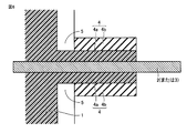
図5を参照して、この構成においては、絶縁体4は、第1の絶縁体部分4aと、第2の絶縁体部分4bとを有している。第1の絶縁体部分4aは、枠体1と一体に構成され、かつ枠体1と同じ材料よりなっている。この第1の絶縁体部分4aは、電極2または電極3の外周に密着するように形成されている。第2の絶縁体部分4bは、その第1の絶縁体部分4aの外周面および先端面を覆うように形成されている。
図6を参照して、この構成においては、図5の構成と同様に、絶縁体4は、第1の絶縁体部分4aと、第2の絶縁体部分4bとを有している。第1の絶縁体部分4aは、枠体1と一体に構成され、かつ枠体1と同じ材料よりなっている。この第1の絶縁体部分4aは、電極2または電極3の外周に密着するように形成されている。第2の絶縁体部分4bは、その第1の絶縁体部分4aの外周面を覆い、かつ第1の絶縁体部分4aの先端面を覆わないように形成されている。
図5および図6のいずれの構成においても、第2の絶縁体部分4bと枠体1との間には送風経路となる空間5または筺体5が配置されていてもよい。
図5および図6のいずれの構成においても、枠体1と第1の絶縁体部分4aとをモールド材で一体に形成することにより、第1の絶縁体部分4aを第1の電極2または第2の電極3の外周面に密着させることができる。第1の絶縁体部分4aをモールド材で形成する場合には、第2の絶縁体部分4bと電極2、3の枠体1からの突出開始部分(根元)になる部分とをシール部材で封をした状態でモールド材が注入されることにより枠体1と第1の絶縁体部分4aとが形成される。
また上記の方法でモールド材に代えて液体ゴムを注入することにより枠体1と第1の絶縁体部分4aとが形成されてもよい。この場合にも、硬化後のゴムよりなる第1の絶縁体部分4aを第1の電極2または第2の電極3の外周面に密着させることができる。
また電極2、3の外周に絶縁体を密着させて形成する方法としては、液状に溶かした樹脂中に、電極2、3の絶縁体で覆いたいところまで差し込んだ後に、その樹脂を硬化させる方法もある。
次に、本実施の形態のイオン発生素子10が用いられたイオン発生装置100の構成について図7~図13を用いて説明する。
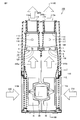
図7および図8を参照して、本実施の形態に係るイオン発生装置100は、イオン発生素子10と、イオンセンサ(検出部)101と、筺体110と、第1および第2ダクト117、118と、吹出筒113、114と、送風機構(羽根車40、41およびモータ30)とを主に有している。
筺体110は、互いに組み合わされる上部筐体111と下部筐体112とを有し、かつ略直方体の形状を有している。上部筐体111と下部筐体112とは、スナップフィット部材により係合しており、着脱自在に組み合わされている。
上部筐体111は、上部に2つの嵌合孔を有している。2つの嵌合孔のうちの一方の嵌合孔に、吹出筒113が着脱可能に嵌め込まれている。2つの嵌合孔のうちの他方の嵌合孔に、吹出筒114が着脱可能に嵌め込まれている。吹出筒113、114は、縦断面においてテーパ状の外形を有している。
吹出筒113の上端が、吹出口113aとなる。吹出筒113の下端を覆うように、防護網115が配置されている。吹出筒114の上端が、吹出口114aとなる。吹出筒114の下端を覆うように、防護網116が配置されている。防護網115、116は、外部から指などの異物が挿入されるのを防ぐために設けられている。
下部筐体112は、側部に2つの吸込口112a、112bを有している。一方の吸込口112aと対向するように、下部筐体112内に羽根車40が配置されている。他方の吸込口112bと対向するように、下部筐体112内に羽根車41が配置されている。
羽根車40、41は、外縁に対し回転中心側が回転方向へ変位する複数の羽根を有する多翼羽根車である。言い換えると、羽根車40、41は、円筒形状をなすシロッコ羽根車である。羽根車40、41は、一端に軸受板を有している。軸受板の中心に、軸孔が設けられている。この軸孔にモータ30の出力軸が取付けられている。
羽根車40、41は、吸込口112a、112bと対向する面に貫通孔を有している。この貫通孔から中心部の空洞へ吸込んだ空気などの気体を外周部の羽根同士の間から放出するように、羽根車40、41が構成されている。羽根車40、41とモータ30とから送風機構が構成されている。
羽根車40から放出された気体と、羽根車41から放出された気体とを別々に流通させるために、イオン発生装置100は2つの流路を有している。
2つの流路のうちの第1流路は、吸込口112aから吸い込まれて羽根車40から放出された気体の流路であり、第1ダクト117により構成されている。すなわち、第1ダクト117は、送風機構により送風された気体の一部が流通する第1流路を構成している。
第1ダクト117の上部は、平面視矩形状で上下方向に延びる筒状の外形を有している。第1ダクト117の下部は、羽根車40の周囲を羽根車40の外形に沿って囲むように側面視略円形状で上方が開放した筒状の外形を有している。
第1ダクト117は、上端に吹出筒113の下端と対向する開口を有している。この開口を塞ぐように、第1ダクト117の上端に、防護網115が取り付けられている。第1ダクト117の上端の開口は、防護網115によって完全に覆われている。
2つの流路のうちの第2流路は、吸込口112bから吸い込まれて羽根車41から放出された気体の流路であり、第2ダクト118により構成されている。すなわち、第2ダクト118は、送風機構により送風された気体の残部が流通する第2流路を構成している。第2ダクト118は、第1ダクト117に隣接して位置している。
第2ダクト118の上部は、平面視矩形状で上下方向に延びる筒状の外形を有している。第2ダクト118の下部は、羽根車41の周囲を羽根車41の外形に沿って囲むように側面視略円形状で上方が開放した筒状の外形を有している。
第2ダクト118は、上端に吹出筒114の下端と対向する開口を有している。この開口を塞ぐように、第2ダクト118の上端に、防護網116が取り付けられている。第2ダクト118の上端の開口は、防護網116によって完全に覆われている。
イオン発生装置100は、第1ダクト117および第2ダクト118に着脱自在に装着されるイオン発生素子10を有している。イオン発生素子10は、たとえば正イオン発生部120および負イオン発生部130を含む。
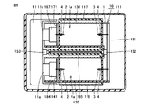
図9~図12を参照して、イオン発生素子10は、枠体(支持部)1と、第1の電極2と、第2の電極3と、絶縁体4とを主に有している。枠体1には、2つの貫通孔(開口部)1aが形成されている。2つの貫通孔1aの各々は風路の少なくとも一部を構成している。2つの貫通孔1aの一方は正イオン発生部120に対応し、他方は負イオン発生部130に対応する。
正イオン発生部120および負イオン発生部130のそれぞれにおいて、第1の電極2は、貫通孔1a内に突き出すように枠体1に支持され、かつ貫通孔1a内に位置する先端部を有している。第2の電極3は、貫通孔1a内に突き出すように枠体1に支持され、かつ貫通孔1a内に位置する先端部を有している。
第2の電極3は第1の電極2の延びる方向の延長線上に位置し、かつ先端部は貫通孔1a内で先端部と離れて対向している。つまり第1および第2の電極2、3は仮想の直線に沿って一直線上に配置されている。
第1の電極2の外周には絶縁体4が形成されている。この絶縁体4は、第1の電極2の先端部を露出し、かつ枠体1から貫通孔1a内に突き出した第1の電極2の部分のうち先端部よりも枠体1側の部分の外周に密着して形成されている。
同様に、第2の電極3の外周にも絶縁体4が形成されている。この絶縁体4は、第2の電極3の先端部を露出し、かつ枠体1から貫通孔1a内に突き出した第2の電極3の部分のうち先端部よりも枠体1側の部分の外周に密着して形成されている。
正イオン発生部120における第1の電極2の延長線と負イオン発生部130における第1の電極2の延長線とが平行となるように各第1の電極2が配置されている。
イオン発生素子10においては、直方体状の正イオン発生部120の貫通孔1aと直方体状の負イオン発生部130の貫通孔1aとが平行に並んでいる。正イオン発生部120の貫通孔1aと負イオン発生部130の貫通孔1aとの間には、所定の間隙1bが設けられている。イオン発生素子10の骨格は、樹脂成型品の枠体1により構成されている。
主に図9および図12を参照して、正イオン発生部120の第1の電極2は、第1電極基板141を貫通するように設けられている。第1電極基板141の一方の主面側に突出している第1の電極2の先端部は、枠体1を貫通して開口1a内に位置している。第1電極基板141の他方の主面側に突出している第1の電極2の根元部は、第1電極基板141の他方の主面上に設けられた第1コネクタ184と電気的に接続されている。第1電極基板141および第1コネクタ184は、枠体1の他方端の空洞部内に収容されている。
負イオン発生部130の第1の電極2は、第2電極基板171を貫通するように設けられている。第2電極基板171の一方の主面側に突出している第1の電極2の先端部は、枠体1を貫通して開口1a内に位置している。第2電極基板171の他方の主面側に突出している第1の電極2の根元部は、第2電極基板171の他方の主面上に設けられた第2コネクタ187と電気的に接続されている。第2電極基板171および第2コネクタ187は、枠体1の他方端の空洞部内に収容されている。
正イオン発生部120の第2の電極3と負イオン発生部130の第2の電極3との各々は、第3電極基板151を貫通するように設けられている。第3電極基板151の主面上には、図示しない導電パターンが設けられている。本実施の形態においては、正イオン発生部120の第2の電極3と負イオン発生部130の第2の電極3とが、導電パターンにより互いに接続されて同電位を有している。導電パターンは、第3電極基板151の主面上に設けられた第3コネクタ152と電気的に接続されている。
第3電極基板151および第3コネクタ152は、枠体1の一方端の空洞部内に収容されている。第3コネクタ152の先端は、枠体1に設けられた間隙1bに面している。
図8を参照して、上部筐体111内において、第1ダクト117および第2ダクト118の側方に、電源回路ユニット11および制御部12が設けられている。
制御部12は、図示しない制御基板および電源部などを含む。電源部は、図8に示すように下部筐体112の下部から引き出されて商用電源に接続されるAC(alternating current)コード90と図示しない配線により接続されて、交流電流を供給可能である。制御部12は、第1ダクト117および第2ダクト118に固定されている。
電源回路ユニット11は、イオン発生素子10と電気的に接続されることにより、正イオン発生部120の第1の電極2に正電圧を印加し、かつ負イオン発生部130の第1の電極2に負電圧を印加可能である。また電源回路ユニット11は、正イオン発生部120および負イオン発生部130の各々の第2の電極3に0電位を印加可能である。これにより、正イオン発生部120および負イオン発生部130の各々の第1の電極2は放電電極に対応し、正イオン発生部120および負イオン発生部130の各々の第2の電極3は誘導電極に対応する。
具体的には、図9を参照して、電源回路ユニット11は、第1コネクタ184と接続される第1端子11aと、第2コネクタ187と接続される第2端子11bとを有している。第1端子11aおよび第1コネクタ184を経由して、電源回路ユニット11から正イオン発生部120の第1の電極2に正電圧が印加可能である。第2端子11bおよび第2コネクタ187を経由して、電源回路ユニット11から負イオン発生部130の第2の電極2に負電圧が印加可能である。
電源回路ユニット11は、昇圧トランス17(図14)の2次巻線に接続された第3端子153を有している。第3端子153は、導線185により第3コネクタ152と電気的に接続されている。
第1コネクタ184と第1端子11a、第2コネクタ187と第2端子11b、および、第3コネクタ152と第3端子153とは、それぞれ着脱可能に接続されている。それにより、イオン発生素子10が第1ダクト117および第2ダクト118に着脱自在に装着されている。
図13を参照して、上部筐体111が下部筐体112から取り外された状態で、イオン発生素子10を第1ダクト117および第2ダクト118に着脱することが可能である。
第1ダクト117の上側の壁部には、イオン発生素子10を着脱するための第1開口117aが設けられている。また、第1ダクト117の上側の壁部には、第1開口117aと対向する位置に、イオン発生素子10を着脱するための開口117bが設けられている。
同様に、第2ダクト118の上側の壁部には、第1開口117aと連続するように延在する、イオン発生素子10を着脱するための図示しない第2開口が設けられている。また、第2ダクト118の上側の壁部には、第2開口と対向する位置に、イオン発生素子10を着脱するための開口が設けられている。
イオン発生素子10を第1ダクト117および第2ダクト118に対して矢印60で示す方向に移動させることにより、イオン発生素子10を第1ダクト117および第2ダクト118に着脱することが可能である。
図8を参照して、イオン発生素子10が第1ダクト117および第2ダクト118に装着された状態において、負イオン発生部130が第1開口117aに挿通されており、負イオン発生部130の第1および第2の電極2、3が第1流路の横断面における両端に互いに離れて位置している。なお、負イオン発生部130の第1および第2の電極2、3は、必ずしも第1流路の横断面における両端に位置しなくてもよく、少なくとも第1流路内に位置していればよい。
また、正イオン発生部120が第2開口に挿通されており、正イオン発生部120の第1および第2の電極2、3が第2流路の横断面における両端に互いに離れて位置している。なお、正イオン発生部120の第1および第2の電極2、3は、必ずしも第2流路の横断面における両端に位置しなくてもよく、少なくとも第2流路内に位置していればよい。
このように、イオン発生素子10を第1ダクト117および第2ダクト118に装着することにより、別々の流路に正イオン発生部120と負イオン発生部130とを配置することができる。また、負イオン発生部130の貫通孔1aにより第1流路の一部を構成することができる。同様に、正イオン発生部120の貫通孔1aにより第2流路の一部を構成することができる。
図13を参照して、電源回路ユニット11は、制御部12に対して矢印70で示す方向に移動させられることにより取り外し可能に接続されている。すなわち、電源回路ユニット11は、第1ダクト117および第2ダクト118に着脱自在に装着されている。具体的には、電源回路ユニット11および制御部12の各々が、互いに取り外し可能に係合する端子部を有している。
上記のように、イオン発生素子10と電源回路ユニット11と制御部12とを互いに接続することにより、電源回路が構成されている。
次に、イオン発生素子10と電源回路ユニット11と制御部12とを互いに接続することにより構成される電源回路の構成について図14を用いて説明する。
図14を参照して、電源回路ユニット11は、昇圧トランス17を有している。また、電源回路ユニット11は、昇圧トランス17の一次側と制御部12の電源部との間に接続された電源回路を有している。
昇圧トランス17の2次側に、ダイオード18およびダイオード19が並列に接続されている。昇圧トランス17の2次側からは、商用交流電圧を昇圧した昇圧交流電圧が、ダイオード18およびダイオード19から出力される。
ダイオード18のカソード端子は、正イオン発生部120の第1の電極2と電気的に接続されている。この結果、昇圧トランス17の2次側から出力される昇圧交流電圧の正電圧が正イオン発生部120の第1の電極2に印加可能である。
ダイオード19のアノード端子は、負イオン発生部130の第1の電極2と電気的に接続されている。この結果、昇圧トランス17の2次側から出力される昇圧交流電圧の負電圧が負イオン発生部130の第1の電極2に印加可能である。正イオン発生部120および負イオン発生部130の各々の第2の電極3には、ともに、昇圧トランス17の2次側の電圧が印加可能である。
制御部12の電源部から高電圧が印加されると、正イオン発生部120の第1および第2の電極2、3の間でコロナ放電が起こって正イオンが発生する。また負イオン発生部130の第1および第2の電極2、3の間でコロナ放電が起こって負イオンが発生する。
正イオン発生部120の第1および第2の電極2、3の間、および負イオン発生部130の第1および第2の電極2、3の間の電位差は、3kV以上10kV以下であることが好ましい。電位差が3kVより小さい場合、コロナ放電が生じにくく、イオンを十分に発生させることができない。電位差が10kVより大きい場合、アーク放電が起こる可能性が高くなり、イオン発生装置100が故障する可能性がある。
本実施の形態においては、正イオン発生部120および負イオン発生部130の各々の第2の電極3の電位が0電位とされている。ここで、0電位とは、正イオン発生部および負イオン発生部の各々の第2の電極3を接地させる、または正イオン発生部120および負イオン発生部130の各々の第2の電極3を電気的に浮かせることにより得られる電位であり、0Vおよび0V近傍を含む。
本実施の形態においては、上述の通り、正イオン発生部120および負イオン発生部130の各々の第2の電極3を、第3コネクタ152、第3端子153および導線185により接続して0電位にしている。これにより、正イオン発生部120および負イオン発生部130の各々の第2の電極3の電位を安定させて、正イオン発生部120および負イオン発生部130における放電を安定させることができる。
上記の構成により、正イオンの放出と負イオンの放出とは、昇圧交流電圧の半周期毎に交互に行なわれる。なお、本実施の形態においては交流電源を用いたが、直流電源が用いられてもよい。
イオン発生装置100において、第1流路を上記のように構成することにより、図7の矢印210で示すように吸込口112aから吸い込まれた気体は、矢印210aで示すように送風機構により送風されて第1流路内を上昇して負イオン発生部130を通過し、吹出口113aから矢印210bで示すように吹き出される。その結果、送風機構により送風された気体の一部によって、負イオン発生部の第1および第2の電極2、3の間で発生した負イオンが吹出口113aから放出される。
また第2流路を上記のように構成することにより、図7の矢印220で示すように吸込口112bから吸い込まれた気体は、矢印220aで示すように送風機構により送風されて第2流路内を上昇して正イオン発生部120を通過し、吹出口114aから矢印220bで示すように吹き出される。その結果、送風機構により送風された気体の残部によって、正イオン発生部の第1および第2の電極2、3の間で発生した正イオンが吹出口114aから放出される。
次に、イオンセンサ(検出部)101による電極交換の表示のための構成およびその制御動作について図7、図15および図16を用いて説明する。
図7を参照して、イオンセンサ101は、正イオン発生部120および負イオン発生部130の各々の下流側に配置されており、正イオン発生部120と吹出口114aとの間、および負イオン発生部130と吹出口113aとの間に配置されている。イオンセンサ101は、第1および第2ダクト117、118の壁面に設置されている。このイオンセンサ101は、イオン発生素子10(正イオン発生部120、負イオン発生部130)で生じる放電の有無を検出するためのものである。
図15を参照して、このイオンセンサ101には制御部102が電気的に接続されており、制御部102には表示部103が電気的に接続されている。制御部102は、イオンセンサ101の検出結果から放電の有無を判断し、その判断結果に基づいた信号を出力するためのものである。具体的には、制御部102は、イオンセンサ101の出力が所定値以下になった場合、イオンの発生量が減少し規定以下になった(この状態を「放電が止まった」と表現する)と判断する。
表示部103は、制御部102で放電が無いと判断された結果を受けて電極交換の表示を行うためのものである。この表示部103は使用者の目に触れるように筺体110の外側に配置されており、たとえば点滅可能なランプからなっている。
図16を参照して、制御動作においては、まずイオンセンサ101によりイオン発生素子10(正イオン発生部120、負イオン発生部130)で生じる放電の有無が検出される(ステップS1)。このイオンセンサ101からの検出信号が制御部102に入力される。制御部102では、イオンセンサ101の検出信号に基づいてイオン発生素子10(正イオン発生部120、負イオン発生部130)で放電があったか否かの判断がなされる(ステップS2)。
制御部102で放電があったと判断された場合には、イオンセンサ101からの検出信号に基づく制御部102による判断(ステップS2)が引き続き行われる。制御部102で放電が止まったと判断された場合には、制御部102から出力された信号に基づいて表示部103にて電極交換の表示がなされる(ステップS3)。具体的には、表示部103のランプ(不図示)を点滅させることで、使用者に電極ユニットの交換を促す。このようにして表示部103における電極交換の表示が行われる。
図7~図13に示すイオン発生素子10として図1のタイプのものについて説明したが、このイオン発生素子10として図2~図4のいずれのタイプのものが用いられてもよい。
次に、本実施の形態の作用効果について説明する。
本実施の形態におけるイオン発生素子10によれば、絶縁体4が第1の電極2のうちの先端部2aよりも枠体1側の部分の外周に密着して形成されている。または絶縁体4が第2の電極3のうちの先端部3aよりも枠体1側の部分の外周に密着して形成されている。このため第1の電極2が、第1の電極2で生じる放電により先端部2aから絶縁体4まで消耗することにより、第1の電極2による放電を停止させることができる。また第2の電極3が、第2の電極3で生じる放電により先端部3aから絶縁体4まで消耗することによっても、第2の電極3による放電を停止させることができる。よって、第1の電極2の先端部2aから絶縁体4までの部分の長さ、第2の電極3の先端部3aから絶縁体4までの部分の長さなどを調整することで、放電による電極の消耗でイオン性能が徐々に低下していく期間を最小限に制御することが可能となる。また上記のイオン性能低下期間の制御の容易化を、第1または第2の電極2、3の外周に絶縁体4を密着させるという簡易な構成で実現することができる。
本実施の形態におけるイオン発生素子10によれば、絶縁体4が第1の電極2のうちの先端部2aよりも枠体1側の部分の外周に密着して形成されている。または絶縁体4が第2の電極3のうちの先端部3aよりも枠体1側の部分の外周に密着して形成されている。このため第1の電極2が、第1の電極2で生じる放電により先端部2aから絶縁体4まで消耗することにより、第1の電極2による放電を停止させることができる。また第2の電極3が、第2の電極3で生じる放電により先端部3aから絶縁体4まで消耗することによっても、第2の電極3による放電を停止させることができる。よって、第1の電極2の先端部2aから絶縁体4までの部分の長さ、第2の電極3の先端部3aから絶縁体4までの部分の長さなどを調整することで、放電による電極の消耗でイオン性能が徐々に低下していく期間を最小限に制御することが可能となる。また上記のイオン性能低下期間の制御の容易化を、第1または第2の電極2、3の外周に絶縁体4を密着させるという簡易な構成で実現することができる。
また絶縁体4を第1または第2の電極2、3の外周に密着させることにより、絶縁体4と第1または第2の電極2、3との間に隙間が生じることが防止される。これにより、その隙間で発生する微弱な放電も防止することができ、より的確に規定時間内で放電を停止させることが可能となる。
また第1の電極2と第2の電極3との双方の外周に絶縁体4を形成することにより、第1および第2の電極2、3の双方で、放電による電極の消耗でイオン性能が徐々に低下していく期間を最小限に制御することが可能となる。
図5および図6に示すように、絶縁体4が枠体1と一体の部分を含んでいることにより、イオン発生素子10の部品点数を削減することができる。
また第1の電極2の延長線A-A上に第2の電極3が配置され、かつ第1の電極2の先端部2aと第2の電極3の先端部3aとが互いに離れて対向している。これにより、第1および第2の電極2、3の間で生じる放電により第1および第2の電極2、3の双方が消耗することで、先端部2a、3aの距離が拡大して放電が停止するように構成されている。このような構成とすることで、先端部2a、3aの間隔などを調整することで、放電による電極の消耗でイオン性能が徐々に低下していく期間を最小限に制御することができる。
また第1および第2の電極2、3の各々は貫通孔1aの中心線A-Aに沿って配置されているため、風路に対するイオンの分布を均一にすることが容易となる。また第1および第2の電極2、3は貫通孔1aの中心線A-Aに沿って配置されているため、第1および第2の電極2、3が中心線A-Aに対して片寄って配置される場合よりもイオンが風路壁面に取り込まれにくくなる。
また図1のイオン発生素子10においては第1および第2の電極2、3の双方が針状の形状を有している。このため、電極を板状またはリング状に形成する場合に比べて、対向する電極同士間に強い電界を集中させることができる。そのため、放電に必要な印加電圧の増加を抑制しつつ、第1の電極2と第2の電極3との間の距離Dを大きくすることができる。これにより、第1の電極2と第2の電極3との間の距離Dが小さい場合に比べて、第1の電極2(たとえば放電電極)の近傍で発生したイオンを第2の電極3側(たとえば誘導電極側)に吸収されにくくすることができる。具体的には、第1の電極2と第2の電極3との距離Dが大きいため、第1の電極2の近傍で発生したイオンが第2の電極3に吸収される前に、そのイオンを電極間を通過する風によって運ぶことができる。その結果、イオンを効率よく発生させることができる。
また第1の電極2の直径が0.1mm以上0.4mm以下である。これにより、第1の電極2の消耗に要する時間とイオン発生の性能への影響とのバランスを良好にすることができる。
また図1の構成においては第1の電極2と第2の電極3との間の距離Dは、15mm以上200mm以下であることが好ましい。電極間距離Dが15mmより小さい場合、アーク放電が起こりやすくなり、オゾンガスが高い濃度で発生する可能性がある。また、電極同士が近くに位置するため、第1の電極2の近傍で発生したイオンにおいて、第2の電極3に吸収される割合が多くなる。すなわち、イオンの発生効率が低下する。また電極間距離が200mmより大きい場合、コロナ放電が、第1の電極2と第2の電極3との間ではなく、電極の近傍に存在する他の物体と電極との間で生じやすくなる。たとえば、第2の電極3より近くに存在する枠体1の内壁と第1の電極2との間でコロナ放電が生じて、イオンの発生効率が低下することがある。
また図1の構成において、第1の電極2のうち絶縁体4から先端部2aまでの絶縁体4から露出する部分の長さL1aは、第1の電極2のうち枠体1から先端部2aまでの枠体1から突き出した部分の長さL1bの1/2以下である。また第2の電極3のうち絶縁体4から先端部3aまでの絶縁体4から露出する部分の長さL2aは、第2の電極3のうち枠体1から先端部3aまでの枠体1から突き出した部分の長さL2bの1/2以下である。
これにより、第1および第2の電極2、3の絶縁体4から露出した部分を枠体1から所定距離だけ離すことができる。このため、第1および第2の電極2、3での放電で生じたイオンが枠体1に吸収されることを抑制することができる。
本実施の形態のイオン発生装置100によれば、イオンセンサ101で放電を検出した結果に基づいて表示部103に電極交換の表示を出すことができるため、使用者は適切な時期に電極の交換を行うことができる。つまり本実施の形態のイオン発生装置100によれば、一定時間までは放電性能を持続させ、それ以降は放電が止まってしまう構造が実現でき、その放電の終了を検出すれば、使用者に電極の交換を知らせ、常に良い性能が得られる状態で使ってもらうことができる。
また正イオンと負イオンとをそれぞれ別々の流路を通過させて放出することにより、流路内における正イオンと負イオンとの中和または再結合を抑制して、第1ダクト117および第2ダクト118内において消滅するイオンの数を低減することができる。
よって、イオン発生装置100から離れた位置まで十分な数の正イオンおよび負イオンを供給して、正イオンと負イオンとを広範囲の空間に高密度で混在させることができる。正イオンをH+(H2O)m(mは任意の自然数)、負イオンをO2
-(H2O)n(nは任意の自然数)とする場合には、正イオンおよび負イオンが浮遊細菌の表面に付着して過酸化水素(H2O2)または水酸基ラジカル(・OH)などの活性種を生成させ、その働きにより殺菌効果を得られる。
このように正イオンおよび負イオンを空気中に放出させることで、空気中に浮遊するカビ菌またはウィルスの分解、ニオイの除去、集塵などの効果を得ることができる。
イオン発生装置100においては、使用時間の経過により放電電極が劣化した場合に、イオン発生素子10を電源回路ユニット11から取り外して容易に交換することができる。また、電源回路ユニット11が劣化した場合に、電源回路ユニット11を制御部12から取り外して容易に交換することができる。
以下、比較例のイオン発生装置と参考例のイオン発生装置とから放出されたイオンの濃度分布を比較した実験例1について説明する。
(実験例1)
図17および図18に示すように、長さ604mm、幅34mmの流路を有する共通ダクト900内に、図示しないクロスフローファンにより電極上で5m/secとなる流速で空気を送風した。
図17および図18に示すように、長さ604mm、幅34mmの流路を有する共通ダクト900内に、図示しないクロスフローファンにより電極上で5m/secとなる流速で空気を送風した。
図17に示すように、参考例においては、共通ダクト900の上部中央に、長さ103mm、幅34mmの流路を有する第1ダクト217と、第1ダクト217との間に20mmの間隔を置いて、長さ103mm、幅34mmの流路を有する第2ダクト218とを設けた。互いに反対側に位置して対向する第1ダクト217の外壁と第2ダクト218の外壁との距離を245mmとした。
第1ダクト217の第2ダクト218側とは反対側の内壁から11.5mm突出する第1の針状電極240を設けた。第1ダクト217の第2ダクト218側の内壁から第1の針状電極240と対向するように11.5mm突出する第2の針状電極250を設けた。第1の針状電極240の先端と第2の針状電極250の先端との距離は80mmとした。
第2ダクト218の第1ダクト217側とは反対側の内壁から11.5mm突出する第1の針状電極270を設けた。第2ダクト218の第1ダクト217側の内壁から第1の針状電極270と対向するように11.5mm突出する第2の針状電極260を設けた。第1の針状電極270の先端と第2の針状電極260の先端との距離は80mmとした。
図18~図20に示す比較例のイオン発生部800と条件を近づけるために、図17に示すように、第1ダクト217内の第1の針状電極240および第2の針状電極250を、第1ダクト217の経路方向(幅方向)の一方側に偏って位置させた。具体的には、第1ダクト217の一方端と他方端との間の経路方向の一方端から8mmの位置に第1の針状電極240および第2の針状電極250の各中心軸が位置するように、第1の針状電極240および第2の針状電極250を配置した。
同様に、第2ダクト218内の第1の針状電極270および第2の針状電極260を、第2ダクト218の経路方向(幅方向)の一方側に偏って位置させた。具体的には、第2ダクト218の一方端と他方端との間の経路方向の一方端から8mmの位置に第1の針状電極270および第2の針状電極260の各中心軸が位置するように、第1の針状電極270および第2の針状電極260を配置した。
図18~図20に示すように、比較例においては、共通ダクト900の上部中央に、長さ235.5mm、幅34mmの流路を有するダクト910を設けた。共通ダクト900内に、図示しないクロスフローファンにより電極上で5m/secとなる流速で空気を送風した。ダクト910の幅方向の一方側の内壁にイオン発生部800を配置した。
イオン発生部800は、電源回路部850(図20)から突出した第1の針状電極810と、第2の針状電極820とを含んでいる。第1および第2の針状電極810、820は互いに間隔を置いて平行に位置している。またイオン発生部800は、第1の針状電極810の先端と所定の間隔を置いて対向する円環状の第1誘導電極830と、第2の針状電極820の先端と所定の間隔を置いて対向する円環状の第2誘導電極840とを含んでいる。
イオン発生部800は、第1の針状電極810および第2の針状電極820の先端がダクト910内の流路と接するように配置されている。
電源回路部850によって、第1の針状電極810に正の高電圧を印加し、第2の針状電極820に負の高電圧を印加して、第1誘導電極830および第2誘導電極840を接地電位に固定することにより、第1の針状電極810の先端近傍から正イオンを、第2の針状電極820の先端近傍から負イオンを発生させた。
図21は、図17に示す参考例にて第1ダクト217および第2ダクト218の上方において電極から250mm離れた位置で計測された正イオンの濃度分布を示すグラフである。図22は、参考例にて第1ダクト217および第2ダクト218の上方において電極から1m離れた位置で計測された正イオンの濃度分布を示すグラフである。
図23は、図17に示す参考例にて第1ダクト217および第2ダクト218の上方において電極から250mm離れた位置で計測された負イオンの濃度分布を示すグラフである。図24は、参考例にて第1ダクト217および第2ダクト218の上方において電極から1m離れた位置で計測された負イオンの濃度分布を示すグラフである。
図25は、図18~図20に示す比較例にてダクト910の上方において電極から250mm離れた位置で計測された正イオンの濃度分布を示すグラフである。図26は、比較例にてダクト910の上方において電極から1m離れた位置で計測された正イオンの濃度分布を示すグラフである。
図27は、図18~図20に示す比較例にてダクト910の上方において電極から250mm離れた位置で計測された負イオンの濃度分布を示すグラフである。図28は、比較例にてダクト910の上方において電極から1m離れた位置で計測された負イオンの濃度分布を示すグラフである。
図21~図28においては、縦軸にダクトの幅方向の座標、横軸にダクトの長さ方向の座標を示し、規格化したイオン濃度を等高線で示している。なお、共通ダクト900内の流路の中心位置を座標軸の0としている。
図21に示すように、参考例にて電極から250mm離れた位置においては、第1ダクト217上の第1の針状電極240側に正イオンの高濃度領域が存在している。図23に示すように、参考例にて電極から250mm離れた位置においては、第2ダクト218上の第1の針状電極270側に負イオンの高濃度領域が存在している。よって、放出直後に正イオンおよび負イオンのほとんどは互いに離れて位置しており、正イオンおよび負イオンの結合消滅が抑制されている。
図22に示すように、参考例にて電極から1m離れた位置においては、正イオンが共通ダクト900の略中心上から放射状に拡散して存在している。図24に示すように、参考例にて電極から1m離れた位置においては、負イオンが共通ダクト900の略中心上から放射状に拡散して存在している。よって、放出された空間の広範囲の領域において正イオンと負イオンとが混在している。
このように参考例においては、イオン発生装置から離れた位置まで十分な数の正イオンおよび負イオンを供給することができることが確認された。
図25に示すように、比較例にて電極から250mm離れた位置においては、正イオンがダクト910の長さ方向の略中心かつ幅方向の一方側の内壁近傍から放射状に拡散して存在している。図27に示すように、比較例にて電極から250mm離れた位置においては、負イオンがダクト910の長さ方向の略中心かつ幅方向の一方側の内壁近傍から放射状に拡散して存在している。よって、放出直後に正イオンおよび負イオンの多くは互いに結合して消滅する。
図26に示すように、比較例にて電極から1m離れた位置においては、正イオンがダクト910の略中心上から放射状に拡散して存在している。図28に示すように、比較例にて電極から1m離れた位置においては、負イオンがダクト910の略中心上から放射状に拡散して存在している。よって、放出された空間において正イオンと負イオンとは混在している。ただし、放出された正イオンおよび負イオンの濃度は、参考例に比較して低く、また、正イオンおよび負イオンの放出された範囲も参考例に比較して狭かった。
この比較例の場合、正イオンと負イオンとが結合することによる、空気中に浮遊するカビ菌またはウィルスの分解、ニオイの除去などの効果をさらに向上できる余地がある。
以下、上記の比較例のイオン発生装置と参考例のイオン発生装置とから放出されたイオンの量を比較した実験例2について説明する。
(実験例2)
実験例1で用いた比較例のイオン発生装置(図17)および参考例のイオン発生装置(図18~図20)を用いて、電極から500mmの位置におけるイオンの量を比較した。なお、イオンの量は、共通ダクト900の幅方向において25mm間隔で5点、長さ方向において50mm間隔で7点の格子状に合計35点で計測した。
実験例1で用いた比較例のイオン発生装置(図17)および参考例のイオン発生装置(図18~図20)を用いて、電極から500mmの位置におけるイオンの量を比較した。なお、イオンの量は、共通ダクト900の幅方向において25mm間隔で5点、長さ方向において50mm間隔で7点の格子状に合計35点で計測した。
以下の表1は、比較例および参考例において、上記35計測点の中で正イオン量の最大値、負イオン量の最大値、および、35計測点におけるイオン量の積分値をまとめたものである。

表1に示すように、比較例における正イオン量の最大値が4.2nA、負イオン量の最大値が3.9nAで、35計測点のイオン量の積分値が39.9nAであった。
参考例における正イオン量の最大値は5.4nAで比較例の129%、負イオン量の最大値は5.1nAで比較例の131%、35計測点のイオン量の積分値が94.1nAで比較例の236%であった。
上記の実験結果から、参考例のイオン発生装置では、比較例のイオン発生装置に比較して、正イオンおよび負イオンを多く供給できていることが確認できた。また、電極間距離を80mmとすることにより、多くのイオンを供給できることが確認された。
(実験例3)
図1に示すように第1および第2の電極2、3を枠体1の貫通孔1aの中心線に沿って配置した場合の貫通孔1a内に生じる電界ベクトルについて調べた。この電界シミュレーションに用いた条件として、貫通孔1aの長さ、幅、高さをそれぞれ50mm、30mm、30mmとし、第1および第2の電極のそれぞれの直径(φ)を0.4mmとし、第1および第2の電極のそれぞれの長さを11.75mmとした。これにより、図29に示すような結果が得られた。
図1に示すように第1および第2の電極2、3を枠体1の貫通孔1aの中心線に沿って配置した場合の貫通孔1a内に生じる電界ベクトルについて調べた。この電界シミュレーションに用いた条件として、貫通孔1aの長さ、幅、高さをそれぞれ50mm、30mm、30mmとし、第1および第2の電極のそれぞれの直径(φ)を0.4mmとし、第1および第2の電極のそれぞれの長さを11.75mmとした。これにより、図29に示すような結果が得られた。
図29に示すように、第1および第2の電極2、3の延長線により2等分される貫通孔のそれぞれの空間内において電界がほぼ線対称に分布していることが分かった。このことから、第1および第2の電極2、3を枠体1の貫通孔1aの中心線に沿って配置することによって、片寄って配置した場合よりも、風路に対するイオンの分布を均一にすることが容易となるとともに、イオンが風路壁面に取り込まれにくくなることが分かった。
今回開示された実施の形態および実験例はすべての点で例示であって制限的なものではないと考えられるべきである。本発明の範囲は上記した説明ではなくて請求の範囲によって示され、請求の範囲と均等の意味および範囲内でのすべての変更が含まれることが意図される。
本発明は、高電圧発生回路、イオン発生素子を備えたイオン発生装置、携帯型電気機器、電池駆動イオン発生装置などに広く適用され得る。
1 枠体、1a 貫通孔、1b 間隙、2 第1の電極、2a 先端部、3 第2の電極、3a 先端部、4 絶縁体、4a 第1の絶縁体部分、4b 第2の絶縁体部分、10 イオン発生素子、11 電源回路ユニット、11a 第1端子、11b 第2端子、12,102 制御部、13,18,19 ダイオード、14 抵抗、15 コンデンサ、16 端子サイリスタ、17 昇圧トランス、30 モータ、40,41 羽根車、90 コード、100 イオン発生装置、101 イオンセンサ、103 表示部、110 筺体、111 上部筐体、112 下部筐体、112a,112b 吸込口、113,114 吹出筒、113a,114a 吹出口、115,116 防護網、117 第1ダクト、117a 第1開口、117b 開口、118 第2ダクト、120 正イオン発生部、130 負イオン発生部、141 第1電極基板、150,830 第1誘導電極、151 第3電極基板、152 第3コネクタ、153 第3端子、160,840 第2誘導電極、171 第2電極基板、184 第1コネクタ、185 導線、187 第2コネクタ、800 イオン発生部、850 電源回路部、900 共通ダクト、910 ダクト。
Claims (5)
- 風路の少なくとも一部を構成する開口部を有する支持部と、
前記開口部内に突き出すように前記支持部に支持され、かつ前記開口部内に位置する第1の先端部を有する第1の電極と、
前記第1の電極の前記第1の先端部を露出し、かつ前記支持部から前記開口部内に突き出した前記第1の電極の部分のうち前記第1の先端部よりも前記支持部側の部分の外周に密着して形成された第1の絶縁体とを備えた、イオン発生素子。 - 前記開口部内に突き出すように前記支持部に支持され、かつ前記開口部内に位置する第2の先端部を有する第2の電極と、
前記第2の電極の前記第2の先端部を露出し、かつ前記支持部から前記開口部内に突き出した前記第2の電極の部分のうち前記第2の先端部よりも前記支持部側の部分の外周に密着して形成された第2の絶縁体とをさらに備え、
前記第1および第2の電極の双方は針状形状を有している、請求項1に記載のイオン発生素子。 - 前記第1の絶縁体は前記支持部と一体の部分を含む、請求項1または2に記載のイオン発生素子。
- 前記第1の電極のうち前記第1の絶縁体から前記第1の先端部までの前記第1の絶縁体から露出する部分の長さは、前記第1の電極のうち前記支持部から前記第1の先端部までの前記支持部から突き出した部分の長さの1/2以下である、請求項1~3のいずれかに記載のイオン発生素子。
- 請求項1~4のいずれかに記載の前記イオン発生素子と、
前記イオン発生素子で生じる放電の有無を検出するための検出部と、
前記検出部で放電が無いと判断した結果を受けて電極交換の表示を行う表示部とを備えた、イオン発生装置。
Applications Claiming Priority (2)
| Application Number | Priority Date | Filing Date | Title |
|---|---|---|---|
| JP2012234657A JP2014086287A (ja) | 2012-10-24 | 2012-10-24 | イオン発生素子およびイオン発生装置 |
| JP2012-234657 | 2012-10-24 |
Publications (1)
| Publication Number | Publication Date |
|---|---|
| WO2014065333A1 true WO2014065333A1 (ja) | 2014-05-01 |
Family
ID=50544708
Family Applications (1)
| Application Number | Title | Priority Date | Filing Date |
|---|---|---|---|
| PCT/JP2013/078724 Ceased WO2014065333A1 (ja) | 2012-10-24 | 2013-10-23 | イオン発生素子およびイオン発生装置 |
Country Status (2)
| Country | Link |
|---|---|
| JP (1) | JP2014086287A (ja) |
| WO (1) | WO2014065333A1 (ja) |
Citations (4)
| Publication number | Priority date | Publication date | Assignee | Title |
|---|---|---|---|---|
| JP2002159880A (ja) * | 2000-11-28 | 2002-06-04 | Koji Abu | 照明具付空気清浄装置 |
| JP2004253192A (ja) * | 2003-02-18 | 2004-09-09 | Keyence Corp | 除電装置および除電装置用脱着ユニット |
| JP2004273293A (ja) * | 2003-03-10 | 2004-09-30 | Keyence Corp | 除電器 |
| JP2011228075A (ja) * | 2010-04-19 | 2011-11-10 | Sharp Corp | イオン発生装置 |
-
2012
- 2012-10-24 JP JP2012234657A patent/JP2014086287A/ja active Pending
-
2013
- 2013-10-23 WO PCT/JP2013/078724 patent/WO2014065333A1/ja not_active Ceased
Patent Citations (4)
| Publication number | Priority date | Publication date | Assignee | Title |
|---|---|---|---|---|
| JP2002159880A (ja) * | 2000-11-28 | 2002-06-04 | Koji Abu | 照明具付空気清浄装置 |
| JP2004253192A (ja) * | 2003-02-18 | 2004-09-09 | Keyence Corp | 除電装置および除電装置用脱着ユニット |
| JP2004273293A (ja) * | 2003-03-10 | 2004-09-30 | Keyence Corp | 除電器 |
| JP2011228075A (ja) * | 2010-04-19 | 2011-11-10 | Sharp Corp | イオン発生装置 |
Also Published As
| Publication number | Publication date |
|---|---|
| JP2014086287A (ja) | 2014-05-12 |
Similar Documents
| Publication | Publication Date | Title |
|---|---|---|
| SG178800A1 (en) | Ion detecting apparatus and ion generating apparatus | |
| WO2014058027A1 (ja) | イオン発生素子およびイオン発生装置 | |
| WO2018189928A1 (ja) | 放電装置および電気機器 | |
| WO2018205721A1 (zh) | 空调器及其负离子发生装置 | |
| JP2013213454A (ja) | 送風装置 | |
| JP5809021B2 (ja) | 送風装置およびイオン発生機 | |
| JP5840888B2 (ja) | イオン送出装置及びそれを備えた電気機器 | |
| CN216976978U (zh) | 空调室内机 | |
| JP2015075282A (ja) | イオン送出装置 | |
| WO2014065333A1 (ja) | イオン発生素子およびイオン発生装置 | |
| CN202637556U (zh) | 离子产生单元和离子送风装置 | |
| JP5273733B2 (ja) | イオン発生装置およびそれを用いた電気機器 | |
| JP2014007028A (ja) | イオン発生装置 | |
| JP2013089295A (ja) | イオン発生機能付き送風装置 | |
| JP5484259B2 (ja) | イオン発生装置および電気機器 | |
| JP2016131144A (ja) | イオン発生装置 | |
| CN112956824B (zh) | 具有净化功能的柜子 | |
| WO2013061713A1 (ja) | イオン送出装置 | |
| CN211619701U (zh) | 电梯及其轿厢内的空气净化器 | |
| JP5774936B2 (ja) | イオン送出装置及びそれを備えた電気機器 | |
| JP2012255389A (ja) | 送風機 | |
| CN217235858U (zh) | 空调室内机 | |
| JP5781839B2 (ja) | イオン発生器付き送風機 | |
| JP2004020025A (ja) | 空気調和機 | |
| JP2016091714A (ja) | イオン発生装置 |
Legal Events
| Date | Code | Title | Description |
|---|---|---|---|
| 121 | Ep: the epo has been informed by wipo that ep was designated in this application |
Ref document number: 13849569 Country of ref document: EP Kind code of ref document: A1 |
|
| NENP | Non-entry into the national phase |
Ref country code: DE |
|
| 122 | Ep: pct application non-entry in european phase |
Ref document number: 13849569 Country of ref document: EP Kind code of ref document: A1 |