WO2014065310A1 - 車高調整装置 - Google Patents
車高調整装置 Download PDFInfo
- Publication number
- WO2014065310A1 WO2014065310A1 PCT/JP2013/078676 JP2013078676W WO2014065310A1 WO 2014065310 A1 WO2014065310 A1 WO 2014065310A1 JP 2013078676 W JP2013078676 W JP 2013078676W WO 2014065310 A1 WO2014065310 A1 WO 2014065310A1
- Authority
- WO
- WIPO (PCT)
- Prior art keywords
- spring
- vehicle height
- jack
- suspension
- suspension spring
- Prior art date
- Legal status (The legal status is an assumption and is not a legal conclusion. Google has not performed a legal analysis and makes no representation as to the accuracy of the status listed.)
- Ceased
Links
Images

Classifications
-
- B—PERFORMING OPERATIONS; TRANSPORTING
- B60—VEHICLES IN GENERAL
- B60G—VEHICLE SUSPENSION ARRANGEMENTS
- B60G15/00—Resilient suspensions characterised by arrangement, location or type of combined spring and vibration damper, e.g. telescopic type
- B60G15/02—Resilient suspensions characterised by arrangement, location or type of combined spring and vibration damper, e.g. telescopic type having mechanical spring
- B60G15/06—Resilient suspensions characterised by arrangement, location or type of combined spring and vibration damper, e.g. telescopic type having mechanical spring and fluid damper
- B60G15/062—Resilient suspensions characterised by arrangement, location or type of combined spring and vibration damper, e.g. telescopic type having mechanical spring and fluid damper the spring being arranged around the damper
- B60G15/063—Resilient suspensions characterised by arrangement, location or type of combined spring and vibration damper, e.g. telescopic type having mechanical spring and fluid damper the spring being arranged around the damper characterised by the mounting of the spring on the damper
-
- B—PERFORMING OPERATIONS; TRANSPORTING
- B60—VEHICLES IN GENERAL
- B60G—VEHICLE SUSPENSION ARRANGEMENTS
- B60G17/00—Resilient suspensions having means for adjusting the spring or vibration-damper characteristics, for regulating the distance between a supporting surface and a sprung part of vehicle or for locking suspension during use to meet varying vehicular or surface conditions, e.g. due to speed or load
- B60G17/02—Spring characteristics, e.g. mechanical springs and mechanical adjusting means
- B60G17/027—Mechanical springs regulated by fluid means
- B60G17/0272—Mechanical springs regulated by fluid means the mechanical spring being a coil spring
-
- B—PERFORMING OPERATIONS; TRANSPORTING
- B60—VEHICLES IN GENERAL
- B60G—VEHICLE SUSPENSION ARRANGEMENTS
- B60G2202/00—Indexing codes relating to the type of spring, damper or actuator
- B60G2202/30—Spring/Damper and/or actuator Units
- B60G2202/31—Spring/Damper and/or actuator Units with the spring arranged around the damper, e.g. MacPherson strut
- B60G2202/312—The spring being a wound spring
-
- B—PERFORMING OPERATIONS; TRANSPORTING
- B60—VEHICLES IN GENERAL
- B60G—VEHICLE SUSPENSION ARRANGEMENTS
- B60G2202/00—Indexing codes relating to the type of spring, damper or actuator
- B60G2202/30—Spring/Damper and/or actuator Units
- B60G2202/32—The spring being in series with the damper and/or actuator
-
- B—PERFORMING OPERATIONS; TRANSPORTING
- B60—VEHICLES IN GENERAL
- B60G—VEHICLE SUSPENSION ARRANGEMENTS
- B60G2500/00—Indexing codes relating to the regulated action or device
- B60G2500/30—Height or ground clearance
Definitions
- the present invention relates to a vehicle height adjusting device.
- a shock absorber that generates a damping force and a suspension spring that urges the shock absorber in the extending direction are provided in parallel between the vehicle body and the wheel in the vehicle.
- the suspension spring absorbs an impact caused by road surface unevenness.
- the shock absorber suppresses the expansion and contraction motion of the suspension spring accompanying the shock absorption. Thereby, it is suppressed that the impact by the road surface unevenness is transmitted to the vehicle body.
- the vehicle height adjusting device includes a movable spring receiver 5 that is movable in the axial direction of the shock absorber 7, and a housing that is fixed to the outer cylinder T of the shock absorber 7 and has a jack chamber J formed inside. 6 and a pump P for sucking and discharging the working fluid in the jack chamber J.
- the movable spring receiver 5 includes a spring guide 50 that supports one end (upper end in FIG. 3) of the suspension spring S1 that biases the shock absorber 7 in the extending direction, and an anti-suspension spring side (upper side in FIG. 1) of the spring guide 50.
- a jack piston 51 which is inserted into the housing 6 so as to be able to protrude and retract and closes the suspension spring side (upper side in FIG. 3) opening of the jack chamber J.
- the working fluid When the vehicle height becomes too low, the working fluid is supplied to the jack chamber J by the pump P. Thereby, since the jack piston 51 is pushed out from the housing 6, the shock absorber 7 can be extended and the vehicle height can be increased. Further, when the vehicle height becomes too high, the working fluid is discharged from the jack chamber J by the pump P. Thereby, since the jack piston 51 is pushed into the housing 6, the shock absorber 7 can be compressed and the vehicle height can be lowered.
- An object of the present invention is to provide a vehicle height adjusting device capable of driving a pump with a smaller force even when a load of a suspension spring is large.
- a vehicle height adjusting device includes one of a housing fixed to an outer cylinder or a piston rod of a shock absorber and having a jack chamber formed therein, and a suspension spring that biases the shock absorber in an extending direction.
- a movable spring receiver that is movable in the direction, a pump that sucks and discharges the working fluid into the jack chamber, and an auxiliary spring that biases the movable spring receiver toward the suspension spring.
- the load of the auxiliary spring is greater than the load of the suspension spring. Is always set to be small.
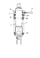
- FIG. 1 is a front view partially showing a state in which a vehicle height adjusting device and a suspension spring according to an embodiment of the present invention are assembled to a shock absorber.
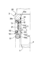
- FIG. 2 is an enlarged view showing the main part of FIG.
- FIG. 3 is a front view partially showing a state in which the vehicle height adjusting device and the suspension spring in the comparative example are assembled to the shock absorber.
- the vehicle height adjusting device 9 includes a movable spring receiver 1 that is movable in the axial direction of the shock absorber 8 and a housing that is fixed to the outer cylinder T of the shock absorber 8 and has a jack chamber J formed inside. 2 and a pump P that sucks and discharges the working fluid in the jack chamber J.
- the movable spring receiver 1 includes a spring guide 10 that supports one end (vehicle body side end) of the suspension spring S1 that biases the shock absorber 8 in the extending direction, and an anti-suspension spring side of the spring guide 10 (upper side in FIG. 1). And a jack piston 11 which is inserted in the housing 2 so as to be able to appear and retract and closes the suspension spring side (lower side in FIG. 1) opening of the jack chamber J.
- the vehicle height adjusting device 9 further includes an auxiliary spring S2 that urges the movable spring receiver 1 toward the suspension spring (lower side in FIG. 1).
- the load of the auxiliary spring S2 is set to be always smaller than the load of the suspension spring S1.
- the shock absorber 8 includes an outer cylinder T connected to the vehicle body side via the vehicle body side bracket B1 and a piston rod R connected to the wheel side via the wheel side bracket B2, and is set upside down. .
- the piston rod R is inserted into the outer cylinder T so as to be movable in the axial direction, and the shock absorber 8 expands and contracts when the piston rod R protrudes and retracts from the outer cylinder T.
- the shock absorber 8 generates a predetermined damping force along with expansion and contraction and suppresses expansion and contraction of the suspension spring S1.
- the structure for the shock absorber 8 to generate the damping force may be any structure, a detailed description of the shock absorber 8 is omitted.
- the shock absorber 8 is set in an inverted type, but may be set in an upright type in which the piston rod R is connected to the vehicle body side and the outer cylinder T is connected to the wheel side.
- the vehicle body side (upper side in FIG. 1) from the approximate center of the outer cylinder T is covered with a cylindrical guide cylinder 3.
- the outer peripheral surface of the guide tube 3 is formed smoothly so that the movable spring receiver 1 can move smoothly along the guide tube 3.
- a bottomed tubular housing 2 is attached to the outer periphery of the vehicle body side (upper side in FIG. 1) of the guide tube 3.
- the housing 2 includes an annular bottom portion 20 and a cylindrical tubular portion 21 that stands substantially vertically from the suspension spring side surface (lower side surface in FIG. 2) of the bottom portion 20.
- the inner peripheral portion 20 a of the bottom portion 20 protrudes inside the tubular portion 21, and the outer peripheral portion 20 b of the bottom portion 20 protrudes outside the tubular portion 21.
- the housing 2 is arranged with the bottom portion 20 facing the vehicle body side (upper side in FIG. 2) and the cylindrical portion 21 facing the suspension spring side (lower side in FIG. 2).
- the bottom portion 20 of the housing 2 is fixed in a state (not shown) that is prevented from rotating at a vehicle body side end portion (upper end portion in FIG. 2) of the guide tube 3.
- the cylindrical portion 21 stands on the outer periphery of the guide cylinder 3 with a predetermined gap from the guide cylinder 3.
- an annular jack chamber J filled with a working fluid made of an incompressible liquid is formed between the tubular portion 21 and the guide tube 3.
- An annular seal 22 that is in close contact with the outer peripheral surface of the guide tube 3 is attached to the inner periphery of the bottom 20 of the housing 2.
- the jack P is connected to a pump P driven by a motor (not shown).
- the pump P sucks and discharges the working fluid into the jack chamber J by being driven by a motor.
- the pump P is an electric pump driven by a motor, but the pump P may be a manual pump driven manually or a pump driven by another drive source. Also good.
- the suspension spring S1 that urges the shock absorber 8 in the extending direction is formed of a coil spring and is disposed on the outer periphery of the shock absorber 8.
- the suspension spring S ⁇ b> 1 is interposed between the movable spring receiver 1 that can move in the axial direction of the shock absorber 8 and the fixed spring receiver 4 that is fixed to the shock absorber 8.
- the movable spring receiver 1 is attached to the outer periphery of the outer cylinder T and disposed on the vehicle body side (upper side in FIG. 1).
- the fixed spring receiver 4 is attached to the piston rod R via the wheel side bracket B2 and is disposed on the wheel side (lower side in FIG. 1).
- the suspension spring S1 biases the movable spring receiver 1 and the fixed spring receiver 4 in a direction in which they are separated from each other. Thereby, the suspension spring S1 biases the shock absorber 8 in the extending direction in which the piston rod R retracts from the outer cylinder T.
- the fixed spring receiver 4 formed in an annular shape is supported by the wheel side bracket B2 and pressed against the wheel side bracket B2 by the suspension spring S1 so as to be fixed so as not to move in the axial direction.
- the movable spring receiver 1 is attached to the outer periphery of a cylindrical guide tube 3 fixed to the outer periphery of the outer tube T.
- the movable spring receiver 1 is continuous with the spring guide 10 that supports the vehicle body side end (one side end) of the suspension spring S1 and the anti-suspension spring side (upper side in FIG. 1) of the spring guide 10 and can protrude and retract inside the housing 2.
- a jack piston 11 which closes the suspension spring side (lower side in FIG. 1) opening of the jack chamber J.
- the spring guide 10 and the jack piston 11 are formed in an annular shape and are movable in the axial direction of the shock absorber 8 along the outer peripheral surface of the guide tube 3.
- the spring guide 10 includes an annular bearing portion 10a that supports the vehicle body side end (one side end) of the suspension spring S1, and an inner peripheral edge of the suspension spring side surface (lower surface in FIG. 2) of the support portion 10a. And a cylindrical guide portion 10b that rises substantially vertically.
- the guide portion 10b supports the inner periphery of the vehicle body side end portion (one side end portion) of the suspension spring S1.
- the wall thickness (axial thickness) of the inner peripheral portion 100 of the support portion 10 a is formed to be thicker than the wall thickness of the outer peripheral portion 101. Thereby, the inner peripheral part 100 becomes the shape where the inner peripheral side protruded to the jack piston side (upper side in FIG. 2).
- the jack piston 11 is inserted between the cylindrical portion 21 of the housing 2 and the guide tube 3 so as to be movable, and an annular piston portion 11a for closing the suspension spring side (lower side in FIG. 2) opening of the jack chamber J; And an extending portion 11b connected to the suspension spring side (lower side in FIG. 2) of the portion 11a.
- annular seal 12 is attached to the inner periphery of the piston portion 11a, and an annular seal 13 is attached to the outer periphery of the piston portion 11a.
- the inner peripheral seal 12 is in sliding contact with the outer peripheral surface of the guide tube 3, and the outer peripheral seal 13 is in sliding contact with the inner peripheral surface of the cylindrical portion 21 of the housing 2.
- the axial dimension of the extending portion 11b is such that the extending portion 11b is suspended even when the movable spring receiver 1 is at the most retracted position and the jack piston 11 is at the minimum jack position where the jack piston 11 enters the housing 2 most.
- the spring side end portion (lower end portion in FIG. 2) is set so as to protrude downward from the cylindrical portion 21 of the housing 2. That is, the suspension spring side end portion (lower end portion in FIG. 2) of the extending portion 11 b always protrudes from the housing 2.
- the auxiliary spring S2 that urges the movable spring receiver 1 toward the suspension spring is a coil spring and is arranged on the outer periphery of the cylindrical portion 21 of the housing 2.
- the auxiliary spring S ⁇ b> 2 is interposed between the outer peripheral portion 101 of the support portion 10 a of the spring guide 10 and the outer peripheral portion 20 b of the bottom portion 20 of the housing 2 in a compressed state. That is, the suspension spring S1 and the auxiliary spring S2 are arranged in series, and the spring guide 10 is sandwiched between the suspension spring S1 and the auxiliary spring S2.
- the force acting on the suspension spring S1 and the auxiliary spring S2 in a state where the vehicle height adjusting device 9 and the suspension spring S1 are assembled to the shock absorber 8 is referred to as a load.
- the load of the auxiliary spring S2 is greatest when the movable spring receiver 1 is most retracted and the jack piston 11 is at the minimum jack position where the jack piston 11 enters the housing 2 most.
- the load of the auxiliary spring S2 at this time is referred to as a maximum load when the auxiliary spring S2 is assembled.
- the load of the suspension spring S1 is the smallest when the jack piston 11 is at the jack minimum position and the shock absorber 8 is fully extended.
- the load of the suspension spring S1 at this time is referred to as a minimum load when the suspension spring is assembled. Since the maximum load when the auxiliary spring S2 is assembled is set to be smaller than the minimum load when the suspension spring S1 is assembled, when the vehicle height adjusting device 9 and the suspension spring S1 are assembled to the shock absorber 8, The load of the auxiliary spring S2 is always smaller than the load of the suspension spring S1.
- the right side of the center line X shows the vehicle height adjusting device 9 when the movable spring receiver 1 is at the most advanced position and the jack piston 11 is at the maximum jack position where the jack piston 11 is most retracted from the housing 2.
- the pump P is driven to supply the working fluid to the jack chamber J
- the jack piston 11 is pushed out of the housing 2.
- the outer cylinder T is pushed upward in FIG. 1, the shock absorber 8 is extended, and the vehicle height is increased.
- the left side of the center line X shows the vehicle height adjusting device 9 at the minimum jack position where the movable spring receiver 1 is most retracted and the jack piston 11 is most advanced into the housing 2.
- the pump P is driven to discharge the working fluid from the jack chamber J
- the jack piston 11 is pushed into the housing 2.
- the outer cylinder T moves downward in FIG. 1, the shock absorber 8 is compressed, and the vehicle height decreases.
- the vehicle height adjusting device 9 includes a movable spring receiver 1 that is movable in the axial direction of the shock absorber 8, a housing 2 that is fixed to the outer cylinder T of the shock absorber 8 and that has a jack chamber J formed therein, and a jack chamber J And a pump P for sucking and discharging the working fluid.
- the movable spring receiver 1 supports one end (vehicle body side end) of the suspension spring S1 that urges the shock absorber 8 in the extending direction, and the anti-suspension spring side (upper side in FIG. 1) of the spring guide 10. And a jack piston 11 that is inserted inside the housing 2 so as to be able to appear and retract and closes the suspension spring side (lower side in FIG. 1) opening of the jack chamber J.
- the vehicle height adjusting device 9 includes an auxiliary spring S2 that biases the movable spring receiver 1 toward the suspension spring side (lower side in FIG. 1).
- the load of the auxiliary spring S2 is set to be always smaller than the load of the suspension spring S1.
- the auxiliary spring S2 urges the movable spring receiver 1 toward the suspension spring (the lower side in FIG. 1), and exerts a force in a direction in which the suspension spring S1 is compressed.
- the auxiliary spring S2 helps the jack piston 11 to advance and is smaller.
- the working fluid can be supplied to the jack chamber J by driving the pump P with force.
- the pump P when the pump P is an electric pump driven by a motor, the motor load can be reduced, so that the durability of the motor can be improved. Even when the pump P is a manually driven pump, the work load for driving the pump P can be reduced.
- the spring guide 10 and the jack piston 11 constituting the movable spring receiver 1 are separate bodies, and the spring guide 10 and the jack piston 11 are connected by contact. Since the load of the auxiliary spring S2 is set to be always smaller than the load of the suspension spring S1, the spring guide 10 is always pressed against the jack piston 11 by the suspension spring S1. Therefore, the spring guide 10 and the jack piston 11 can be maintained in a connected state without fitting and bonding the spring guide 10 and the jack piston 11 by bonding or the like.
- the load of the auxiliary spring S2 is always set to be smaller than the load of the suspension spring S1. Therefore, it can suppress that the jack chamber J becomes a negative pressure.
- the housing 2 is fixed to the outer cylinder T, and includes a cylindrical cylindrical portion 21 that forms an annular jack chamber J with the outer cylinder T.
- the auxiliary spring S ⁇ b> 2 is a coil spring and is attached to the outer periphery of the tubular portion 21. Therefore, the assembly of the auxiliary spring S2 can be facilitated. Furthermore, since the auxiliary spring S2 is disposed on the outer periphery of the jack chamber J, the vehicle height adjusting device 9 can be formed compactly.
- the spring guide 10 and the jack piston 11 are separate bodies, and are connected by contacting each other. Therefore, the assembly of the movable spring receiver 1 can be facilitated as compared with the case where the spring guide 10 and the jack piston 11 are integrally formed, or are joined by fitting, adhesion or the like.
- the spring guide 10 and the jack piston 11 are formed as separate bodies and are connected only by contacting each other, if a gap is generated between the spring guide 10 and the jack piston 11, the spring guide 10 and the jack piston 11 are connected. There is a possibility that abnormal noise may be generated or scratched when the piston 11 abuts.
- the load of the auxiliary spring S2 is set to be always smaller than the load of the suspension spring S1, and the spring guide 10 and the jack piston 11 are always kept in contact with each other. It is possible to prevent abnormal noises or scratches between 10 and the jack piston 11.
- the jack piston 11 extends between the tubular portion 21 and the outer tube T so as to be able to protrude and retract, and an extension that continues to the suspension spring side (lower side in FIG. 1) of the piston portion 11a. Part 11b. Further, the axial dimension of the extending portion 11b is set so that the suspension spring side end portion of the extending portion 11b always protrudes from the cylindrical portion 21.
- the spring guide 10 can be prevented from coming into contact with the cylindrical portion 21.
- the spring guide 10 abuts on the tubular portion 21
- only the jack piston 11 continues to retreat even after the tubular portion 21 is restricted from moving upward (retracted) in FIG. 10 and the jack piston 11 are separated from each other.
- the axial dimension of the extending portion 11b is set so that the suspension spring side end of the extending portion 11b always protrudes from the tubular portion 21, so that the spring guide 10 is connected to the tubular portion 21. It is possible to easily maintain the spring guide 10 and the jack piston 11 always in contact with each other.
- the housing 2 includes an annular bottom portion 20 that closes an opening on the side opposite to the suspension spring (upper side in FIG. 2) of the jack chamber J, and an inner peripheral portion 20a of the bottom portion 20 protrudes inward from the tubular portion 21 and a bottom portion.
- An outer peripheral portion 20 b of 20 projects outward from the cylindrical portion 21.
- An auxiliary spring S ⁇ b> 2 is interposed between the outer peripheral portion 20 b of the bottom portion 20 and the spring guide 10.
- the vehicle body side end of the auxiliary spring S2 can be supported by the bottom portion 20 of the housing 2, and the auxiliary spring S2 is arranged in series with the suspension spring S1, and the movable spring receiver 1 is placed on the suspension spring side (see FIG. 1 lower side).
- the spring guide 10 and the jack piston 11 are formed as separate bodies, and the spring guide 10 and the jack piston 11 are in contact with each other.
- the spring guide 10 and the jack piston 11 may be connected by fitting, bonding, or the like, or the spring guide 10 and the jack piston 11 may be integrally formed.
- the movable spring receiver 1 that supports one end of the suspension spring S1 is disposed on the vehicle body side, and the fixed spring receiver 4 that supports the other end is disposed on the wheel side.
- the movable spring receiver 1 may be disposed on the wheel side, and the fixed spring receiver 4 may be disposed on the vehicle body side.
- the housing 2 is fixed to the outer cylinder T of the shock absorber 8, but the housing 2 is fixed to the piston rod R of the shock absorber 8 and the fixed spring receiver 4 is fixed to the outer cylinder T. Also good.
- the guide cylinder 3 is provided on the outer periphery of the outer cylinder T of the shock absorber 8, and the movable spring receiver 1 and the housing 2 are attached to the outer cylinder T via the guide cylinder 3.
- the movable spring receiver 1 and the housing 2 may be directly attached to the outer cylinder T of the shock absorber 8.
- the suspension spring S1 and the auxiliary spring S2 are both configured from a coil spring, but one or both of the suspension spring S1 and the auxiliary spring S2 may be configured from an air spring.
- the shapes and configurations of the movable spring receiver 1 and the housing 2 constituting the vehicle height adjusting device 9 are not limited to the above, and can be changed as appropriate.
Landscapes
- Engineering & Computer Science (AREA)
- Mechanical Engineering (AREA)
- Vehicle Body Suspensions (AREA)
- Fluid-Damping Devices (AREA)
Abstract
車高調整装置は、緩衝器の外筒に固定され内側にジャッキ室が形成されるハウジングと、緩衝器を伸長方向に附勢する懸架ばねの一方側端を支持するばねガイドと、ばねガイドの反懸架ばね側に配置されハウジングの内側に出没可能に挿入されてジャッキ室の懸架ばね側開口を塞ぐジャッキピストンと、を有し、緩衝器の軸方向に移動可能な可動ばね受けと、ジャッキ室に作動流体を吸排するポンプと、可動ばね受けを懸架ばね側に附勢する補助ばねと、を備える。補助ばねの荷重は、懸架ばねの荷重よりも常に小さくなるように設定される。
Description
本発明は、車高調整装置に関する。
車両における車体と車輪との間には、減衰力を発生する緩衝器と、この緩衝器を伸長方向に附勢する懸架ばねと、が並列に設けられる。懸架ばねは、路面凹凸による衝撃を吸収する。緩衝器は、衝撃吸収に伴う懸架ばねの伸縮運動を抑制する。これにより、路面凹凸による衝撃が車体に伝わることが抑制される。
車両の積荷や搭乗者が多い場合、懸架ばね及び緩衝器の圧縮量が大きくなって車高が低くなり過ぎることがある。積荷や搭乗者が少ない場合、懸架ばね及び緩衝器の圧縮量が小さくなって車高が高くなり過ぎることがある。そこで、車高を調整する車高調整装置を車両に搭載することが知られている。
JP2010-149550Aは、車高調整装置を開示している。図3に示すように、車高調整装置は、緩衝器7の軸方向に移動可能な可動ばね受け5と、緩衝器7の外筒Tに固定されて内側にジャッキ室Jが形成されるハウジング6と、ジャッキ室Jに作動流体を吸排するポンプPと、を備える。可動ばね受け5は、緩衝器7を伸長方向に附勢する懸架ばねS1の一方側端(図3中上端)を支持するばねガイド50と、ばねガイド50の反懸架ばね側(図1中上側)に連なるとともにハウジング6の内側に出没可能に挿入されてジャッキ室Jの懸架ばね側(図3中上側)開口を塞ぐジャッキピストン51と、を備える。
車高が低くなり過ぎた場合、ポンプPによってジャッキ室Jに作動流体が供給される。これにより、ジャッキピストン51がハウジング6から押し出されるので、緩衝器7を伸長させて車高を高くすることができる。また、車高が高くなり過ぎた場合、ポンプPによってジャッキ室Jから作動流体が排出される。これにより、ジャッキピストン51がハウジング6内に押し込まれるので、緩衝器7を圧縮させて車高を低くすることができる。
しかし、上記従来の車高調整装置では、車高を上げる方向に調整する場合であって、特に積荷や搭乗者が多く懸架ばねS1の圧縮量が大きい場合、懸架ばねS1の荷重が大きいので、ポンプPを駆動してジャッキ室Jに作動流体を供給し、可動ばね受け5のジャッキピストン51を押し出すために大きな力を必要とする。
この発明の目的は、懸架ばねの荷重が大きい場合であっても、ポンプをより小さい力で駆動することが可能な車高調整装置を提供することである。
本発明のある態様によれば、車高調整装置は、緩衝器の外筒又はピストンロッドに固定され内側にジャッキ室が形成されるハウジングと、緩衝器を伸長方向に附勢する懸架ばねの一方側端を支持するばねガイドと、ばねガイドの反懸架ばね側に配置されハウジングの内側に出没可能に挿入されてジャッキ室の懸架ばね側開口を塞ぐジャッキピストンと、を有し、緩衝器の軸方向に移動可能な可動ばね受けと、ジャッキ室に作動流体を吸排するポンプと、可動ばね受けを懸架ばね側に附勢する補助ばねと、を備え、補助ばねの荷重は、懸架ばねの荷重よりも常に小さくなるように設定される。
以下、添付図面を参照しながら本発明の実施形態について説明する。なお、いくつかの図面を通して付された同じ符号は、同じ部品又は対応する部品を示す。
図1に示すように、車高調整装置9は、緩衝器8の軸方向に移動可能な可動ばね受け1と、緩衝器8の外筒Tに固定され内側にジャッキ室Jが形成されるハウジング2と、ジャッキ室Jに作動流体を吸排するポンプPと、を備える。
可動ばね受け1は、緩衝器8を伸長方向に附勢する懸架ばねS1の一方側端(車体側端)を支持するばねガイド10と、ばねガイド10の反懸架ばね側(図1中上側)に配置されるとともにハウジング2の内側に出没可能に挿入されてジャッキ室Jの懸架ばね側(図1中下側)開口を塞ぐジャッキピストン11と、を備える。
車高調整装置9はさらに、可動ばね受け1を懸架ばね側(図1中下側)に附勢する補助ばねS2を備える。補助ばねS2の荷重は、懸架ばねS1の荷重よりも常に小さくなるように設定される。
緩衝器8は、車体側ブラケットB1を介して車体側に連結される外筒Tと、車輪側ブラケットB2を介して車輪側に連結されるピストンロッドRと、を備え、倒立型に設定される。ピストンロッドRは、外筒T内に軸方向に移動可能に挿入され、ピストンロッドRが外筒Tに対して出没することで、緩衝器8が伸縮する。
緩衝器8は、伸縮に伴い所定の減衰力を発生して懸架ばねS1の伸縮運動を抑制する。なお、緩衝器8が減衰力を発生するための構成は、いかなる構成であってもよいので、緩衝器8の詳細な説明は省略する。また、本実施形態では緩衝器8は倒立型に設定されるが、ピストンロッドRが車体側に連結され外筒Tが車輪側に連結される正立型に設定されてもよい。
外筒Tにおける略中央から車体側(図1中上側)は、筒状のガイド筒3で覆われる。ガイド筒3の外周面は、可動ばね受け1がガイド筒3に沿って円滑に移動できるように滑らかに形成される。ガイド筒3の車体側(図1中上側)部分の外周には、有底筒状のハウジング2が取り付けられる。
図2に示すように、ハウジング2は、環状の底部20と、底部20の懸架ばね側面(図2中下側面)から略垂直に起立する筒状の筒状部21と、を備える。底部20の内周部20aは筒状部21の内側に突出し、底部20の外周部20bは筒状部21の外側に突出する。さらに、ハウジング2は、底部20を車体側(図2中上側)に向け、筒状部21を懸架ばね側(図2中下側)に向けて配置される。
ハウジング2の底部20は、ガイド筒3の車体側端部(図2中上端部)に回り止めされた状態(図示せず)で固定される。筒状部21は、ガイド筒3と所定の隙間をあけた状態でガイド筒3の外周に起立している。さらに、筒状部21とガイド筒3との間には、非圧縮性の液体からなる作動流体が充填される環状のジャッキ室Jが形成される。ハウジング2の底部20の内周には、ガイド筒3の外周面に密着する環状のシール22が取り付けられる。これにより、ジャッキ室Jの反懸架ばね側(図2中上側)開口は、ハウジング2の底部20によって液密に閉塞される。
図1に戻って、ジャッキ室Jには、モータ(図示せず)で駆動されるポンプPが接続される。ポンプPは、モータによって駆動されることでジャッキ室J内に作動流体を吸排する。なお、本実施形態では、ポンプPはモータで駆動される電動ポンプであるが、ポンプPは手動で駆動される手動ポンプであってもよいし、その他の駆動源によって駆動されるポンプであってもよい。
緩衝器8を伸長方向に附勢する懸架ばねS1は、コイルばねからなり、緩衝器8の外周に配置される。懸架ばねS1は、緩衝器8の軸方向に移動可能な可動ばね受け1と、緩衝器8に固定される固定ばね受け4と、の間に介装される。
可動ばね受け1は、外筒Tの外周に取り付けられ車体側(図1中上側)に配置される。固定ばね受け4は、車輪側ブラケットB2を介してピストンロッドRに取り付けられ車輪側(図1中下側)に配置される。懸架ばねS1は、可動ばね受け1と固定ばね受け4とを離間させる方向に附勢する。これにより、懸架ばねS1は、ピストンロッドRが外筒Tから退出する伸長方向に緩衝器8を附勢する。
環状に形成される固定ばね受け4は、車輪側ブラケットB2で支持されるとともに懸架ばねS1で車輪側ブラケットB2に押し付けられ、軸方向に動かないように固定される。
可動ばね受け1は、外筒Tの外周に固定される筒状のガイド筒3の外周に取り付けられる。可動ばね受け1は、懸架ばねS1の車体側端(一方側端)を支持するばねガイド10と、ばねガイド10の反懸架ばね側(図1中上側)に連なるとともにハウジング2の内側に出没可能に挿入されてジャッキ室Jの懸架ばね側(図1中下側)開口を塞ぐジャッキピストン11と、を備える。ばねガイド10及びジャッキピストン11は環状に形成され、ガイド筒3の外周面に沿って緩衝器8の軸方向に移動可能である。
図2に示すように、ばねガイド10は、懸架ばねS1の車体側端(一方側端)を支持する環状の支承部10aと、支承部10aの懸架ばね側面(図2中下面)の内周縁から略垂直に起立する筒状のガイド部10bと、を備える。ガイド部10bは、懸架ばねS1の車体側端部(一方側端部)内周を支持する。支承部10aの内周部100の肉厚(軸方向の厚み)は、外周部101の肉厚よりも厚く形成される。これにより、内周部100は、内周側がジャッキピストン側(図2中上側)に突出した形状になっている。
ジャッキピストン11は、ハウジング2の筒状部21とガイド筒3との間に移動可能に挿入されジャッキ室Jの懸架ばね側(図2中下側)開口を塞ぐ環状のピストン部11aと、ピストン部11aの懸架ばね側(図2中下側)に連なる延設部11bと、を備える。
ピストン部11aの内周には環状のシール12が取り付けられ、ピストン部11aの外周には環状のシール13が取り付けられる。内周側のシール12はガイド筒3の外周面に摺接し、外周側のシール13はハウジング2の筒状部21の内周面に摺接する。これにより、ジャッキピストン11は、ピストン部11aによってジャッキ室Jの懸架ばね側(図2中下側)開口を液密に閉塞する。
延設部11bの軸方向寸法は、可動ばね受け1が最も後退して、ジャッキピストン11がハウジング2内に最も進入しているジャッキ最小位置にある場合であっても、延設部11bの懸架ばね側端部(図2中下端部)がハウジング2の筒状部21から下側に突出するように設定される。つまり、延設部11bの懸架ばね側端部(図2中下端部)は、常にハウジング2から突出している。
可動ばね受け1を懸架ばね側に附勢する補助ばねS2は、コイルばねであり、ハウジング2の筒状部21の外周に配置される。補助ばねS2は、ばねガイド10の支承部10aの外周部101と、ハウジング2の底部20の外周部20bと、の間に圧縮された状態で介装される。つまり、懸架ばねS1と補助ばねS2とが直列に配置され、ばねガイド10が懸架ばねS1と補助ばねS2との間に挟持される。
以下、車高調整装置9及び懸架ばねS1が緩衝器8に組み付けられた状態で懸架ばねS1や補助ばねS2に作用する力を荷重と称する。補助ばねS2の荷重は、可動ばね受け1が最も後退し、ジャッキピストン11がハウジング2内に最も進入しているジャッキ最小位置にある場合、最も大きくなる。このときの補助ばねS2の荷重を補助ばねS2の組み付け時最大荷重と称する。また、懸架ばねS1の荷重は、ジャッキピストン11がジャッキ最小位置にあって、かつ、緩衝器8の最伸長時に、最も小さくなる。このときの懸架ばねS1の荷重を懸架ばねの組み付け時最小荷重と称する。補助ばねS2の組み付け時最大荷重が懸架ばねS1の組み付け時最小荷重よりも小さくなるように設定されるので、車高調整装置9及び懸架ばねS1が緩衝器8に組み付けられた状態にあるとき、補助ばねS2の荷重は、懸架ばねS1の荷重よりも常に小さくなる。
次に、本実施形態における車高調整装置9の動作について説明する。
図1において、中心線Xの右側は、可動ばね受け1が最も前進し、ジャッキピストン11がハウジング2から最も退出しているジャッキ最大位置にある場合の車高調整装置9を示す。ポンプPを駆動してジャッキ室Jに作動流体を供給すると、ジャッキピストン11がハウジング2から押し出される。これにより、外筒Tが図1中上側に押し上げられて緩衝器8が伸長し、車高が上がる。
図1において、中心線Xの左側は、可動ばね受け1が最も後退し、ジャッキピストン11がハウジング2内に最も進入しているジャッキ最小位置における車高調整装置9を示す。ポンプPを駆動してジャッキ室Jから作動流体を排出させると、ジャッキピストン11がハウジング2内に押し込まれる。これにより、外筒Tが図1中下側に移動して緩衝器8が圧縮され、車高が下がる。
次に、本実施形態における車高調整装置9の作用効果について説明する。
車高調整装置9は、緩衝器8の軸方向に移動可能な可動ばね受け1と、緩衝器8の外筒Tに固定され内側にジャッキ室Jが形成されるハウジング2と、ジャッキ室Jに作動流体を吸排するポンプPと、を備える。
可動ばね受け1が緩衝器8を伸長方向に附勢する懸架ばねS1の一方側端(車体側端)を支持するばねガイド10と、ばねガイド10の反懸架ばね側(図1中上側)に配置されるとともにハウジング2の内側に出没可能に挿入されてジャッキ室Jの懸架ばね側(図1中下側)開口を塞ぐジャッキピストン11と、を備える。
さらに、車高調整装置9は、可動ばね受け1を懸架ばね側(図1中下側)に附勢する補助ばねS2を備える。補助ばねS2の荷重は、懸架ばねS1の荷重よりも常に小さくなるように設定される。
つまり、補助ばねS2は、可動ばね受け1を懸架ばね側(図1中下側)に附勢し、懸架ばねS1を圧縮する方向に力を作用させる。これにより、積荷や搭乗者の増加により、緩衝器8及び懸架ばねS1が圧縮されて、懸架ばねS1の荷重が大きい場合であっても、補助ばねS2がジャッキピストン11の前進を助け、より小さい力でポンプPを駆動して、ジャッキ室Jに作動流体を供給することができる。
さらに、ポンプPがモータで駆動される電動ポンプである場合には、モータの負荷を軽減することができるので、モータの耐久性を向上させることできる。また、ポンプPが手動で駆動される手動ポンプである場合にも、ポンプPを駆動するための作業負荷を軽減することができる。
さらに、可動ばね受け1を構成するばねガイド10とジャッキピストン11とが別体であり、ばねガイド10とジャッキピストン11とが当接により連なっている。補助ばねS2の荷重は懸架ばねS1の荷重よりも常に小さくなるように設定されているので、懸架ばねS1によってばねガイド10が常にジャッキピストン11に押し付けられた状態となる。したがって、ばねガイド10とジャッキピストン11とを嵌合、接着等により結合することなく、ばねガイド10とジャッキピストン11とを連なった状態に維持できる。
さらに、ばねガイド10とジャッキピストン11と一体的に形成したり、嵌合、接着等により結合したりしても、補助ばねS2の荷重が懸架ばねS1の荷重よりも常に小さくなるように設定されているので、ジャッキ室Jが負圧になることを抑制することができる。
さらに、ハウジング2は外筒Tに固定され、外筒Tとの間に環状のジャッキ室Jを形成する筒状の筒状部21を備える。また、補助ばねS2はコイルばねからなり、筒状部21の外周に取り付けられる。したがって、補助ばねS2の組み付けを容易にすることができる。さらに、ジャッキ室Jの外周に補助ばねS2が配置されるので、車高調整装置9をコンパクトに形成することができる。
さらに、ばねガイド10とジャッキピストン11とが別体であり、両者が当接することにより連なっている。したがって、ばねガイド10とジャッキピストン11とが一体形成されたり、嵌合、接着等により結合されたりする場合と比較して、可動ばね受け1の組み付けを容易にすることができる。
さらに、ばねガイド10とジャッキピストン11とが別体として形成され、両者が当接することのみで連なっている場合、ばねガイド10とジャッキピストン11との間に隙間が生じると、ばねガイド10とジャッキピストン11とが当接したときに異音が発生したり傷が付いたりする可能性がある。しかし、本実施形態では、補助ばねS2の荷重が懸架ばねS1の荷重よりも常に小さくなるように設定され、ばねガイド10とジャッキピストン11とが常に当接した状態に維持されるので、ばねガイド10とジャッキピストン11との間に異音が生じたり傷が付いたりすることを防止することができる。
さらに、ジャッキピストン11は、筒状部21と外筒Tとの間に出没可能に挿入される環状のピストン部11aと、ピストン部11aの懸架ばね側(図1中下側)に連なる延設部11bとを備える。さらに、延設部11bの懸架ばね側端部が常に筒状部21から突出するように延設部11bの軸方向寸法が設定される。
したがって、ばねガイド10の外径が筒状部21の内径よりも大きく形成されていても、ばねガイド10が筒状部21に当接することを防止することができる。ここで、ばねガイド10が筒状部21に当接した場合、筒状部21で図2中上側への移動(後退)が規制された後も、ジャッキピストン11のみが後退を続け、ばねガイド10とジャッキピストン11とが離間してしまう。しかし、本実施形態では、延設部11bの懸架ばね側端部が常に筒状部21から突出するように延設部11bの軸方向寸法が設定されるので、ばねガイド10が筒状部21に当接することはなく、ばねガイド10とジャッキピストン11とを常に当接させた状態に維持することが容易に可能となる。
さらに、ハウジング2は、ジャッキ室Jの反懸架ばね側(図2中上側)開口を塞ぐ環状の底部20を備え、底部20の内周部20aが筒状部21から内側に突出するとともに、底部20の外周部20bが筒状部21から外側に張り出している。また、底部20の外周部20bとばねガイド10との間に補助ばねS2が介装される。
したがって、ハウジング2の底部20で補助ばねS2の車体側端を支持することができ、補助ばねS2を懸架ばねS1と直列に配置させるとともに、補助ばねS2で可動ばね受け1を懸架ばね側(図1中下側)に附勢することができる。
以上、本発明の実施形態について説明したが、上記実施形態は本発明の適用例の一部を示したに過ぎず、本発明の技術的範囲を上記実施形態の具体的構成に限定する趣旨ではない。
例えば、上記実施形態では、ばねガイド10とジャッキピストン11とが別体として形成され、ばねガイド10とジャッキピストン11とが当接して連なっている。しかし、嵌合、接着等によりばねガイド10とジャッキピストン11とが連なっていてもよいし、ばねガイド10とジャッキピストン11とが一体的に形成されていてもよい。
さらに、上記実施形態では、懸架ばねS1の一方側端を支持する可動ばね受け1が車体側に配置され、他方側端を支持する固定ばね受け4が車輪側に配置されるが、反対に、可動ばね受け1が車輪側に、固定ばね受け4が車体側に配置されていてもよい。
さらに、上記実施形態では、ハウジング2が緩衝器8の外筒Tに固定されるが、ハウジング2が緩衝器8のピストンロッドRに固定され、固定ばね受け4が外筒Tに固定されていてもよい。
さらに、上記実施形態では、緩衝器8の外筒Tの外周に、ガイド筒3が設けられ、可動ばね受け1やハウジング2がガイド筒3を介して外筒Tに取り付けられるが、ガイド筒3を廃し、可動ばね受け1やハウジング2が緩衝器8の外筒Tに直接取り付けられていてもよい。
さらに、上記実施形態では、懸架ばねS1及び補助ばねS2が、共にコイルばねから構成されるが、懸架ばねS1及び補助ばねS2の一方または両方がエアばねから構成されていてもよい。
さらに、車高調整装置9を構成する可動ばね受け1やハウジング2等の形状及び構成は、上記の限りではなく、適宜変更することが可能である。
本願は、2012年10月25日に日本国特許庁に出願された特願2012-235438に基づく優先権を主張し、この出願の全ての内容は参照により本明細書に組み込まれる。
Claims (5)
- 車高調整装置であって、
緩衝器の外筒又はピストンロッドに固定され内側にジャッキ室が形成されるハウジングと、
前記緩衝器を伸長方向に附勢する懸架ばねの一方側端を支持するばねガイドと、前記ばねガイドの反懸架ばね側に配置され前記ハウジングの内側に出没可能に挿入されて前記ジャッキ室の懸架ばね側開口を塞ぐジャッキピストンと、を有し、前記緩衝器の軸方向に移動可能な可動ばね受けと、
前記ジャッキ室に作動流体を吸排するポンプと、
前記可動ばね受けを懸架ばね側に附勢する補助ばねと、
を備え、
前記補助ばねの荷重は、前記懸架ばねの荷重よりも常に小さくなるように設定される、車高調整装置。 - 請求項1に記載の車高調整装置であって、
前記ハウジングは、前記外筒に固定され、前記外筒との間に環状の前記ジャッキ室を形成する筒状の筒状部を有し、
前記補助ばねは、コイルばねによって形成され、前記筒状部の外周に取り付けられる、
車高調整装置。 - 請求項1に記載の車高調整装置であって、
前記ばねガイドと前記ジャッキピストンとは別体であり、前記ばねガイドと前記ジャッキピストンとは当接して連なっている、
車高調整装置。 - 請求項2に記載の車高調整装置であって、
前記ジャッキピストンは、前記筒状部と前記外筒との間に出没可能に挿入される環状のピストン部と、前記ピストン部の懸架ばね側に連なる延設部と、を備え、
前記延設部の軸方向寸法は、前記延設部の懸架ばね側端部が常に前記筒状部から突出するように設定される、
車高調整装置。 - 請求項2に記載の車高調整装置であって、
前記ハウジングは、前記ジャッキ室の反懸架ばね側開口を塞ぐ環状の底部を有し、
前記底部の内周部は前記筒状部から内周側に突出し、前記底部の外周部は前記筒状部から外周側に突出しており、
前記補助ばねは、前記底部の外周部と前記ばねガイドとの間に介装される、
車高調整装置。
Applications Claiming Priority (2)
| Application Number | Priority Date | Filing Date | Title |
|---|---|---|---|
| JP2012235438A JP2014084972A (ja) | 2012-10-25 | 2012-10-25 | 車高調整装置 |
| JP2012-235438 | 2012-10-25 |
Publications (1)
| Publication Number | Publication Date |
|---|---|
| WO2014065310A1 true WO2014065310A1 (ja) | 2014-05-01 |
Family
ID=50544686
Family Applications (1)
| Application Number | Title | Priority Date | Filing Date |
|---|---|---|---|
| PCT/JP2013/078676 Ceased WO2014065310A1 (ja) | 2012-10-25 | 2013-10-23 | 車高調整装置 |
Country Status (2)
| Country | Link |
|---|---|
| JP (1) | JP2014084972A (ja) |
| WO (1) | WO2014065310A1 (ja) |
Cited By (2)
| Publication number | Priority date | Publication date | Assignee | Title |
|---|---|---|---|---|
| CN107161168A (zh) * | 2017-05-26 | 2017-09-15 | 华东交通大学 | 列车转向架上的轨道平顺度动态调整适应装置及控制方法 |
| US20240367473A1 (en) * | 2023-05-05 | 2024-11-07 | GM Global Technology Operations LLC | Variable suspension spring rates using magnetorheological fluid |
Citations (3)
| Publication number | Priority date | Publication date | Assignee | Title |
|---|---|---|---|---|
| JPH0632780U (ja) * | 1992-09-29 | 1994-04-28 | 株式会社ショーワ | 油圧緩衝器の荷重検出構造 |
| JPH0924721A (ja) * | 1995-07-11 | 1997-01-28 | Showa:Kk | 車高調整装置 |
| JPH10299811A (ja) * | 1997-04-25 | 1998-11-13 | Showa:Kk | 車高調整装置及びその使用方法 |
-
2012
- 2012-10-25 JP JP2012235438A patent/JP2014084972A/ja active Pending
-
2013
- 2013-10-23 WO PCT/JP2013/078676 patent/WO2014065310A1/ja not_active Ceased
Patent Citations (3)
| Publication number | Priority date | Publication date | Assignee | Title |
|---|---|---|---|---|
| JPH0632780U (ja) * | 1992-09-29 | 1994-04-28 | 株式会社ショーワ | 油圧緩衝器の荷重検出構造 |
| JPH0924721A (ja) * | 1995-07-11 | 1997-01-28 | Showa:Kk | 車高調整装置 |
| JPH10299811A (ja) * | 1997-04-25 | 1998-11-13 | Showa:Kk | 車高調整装置及びその使用方法 |
Cited By (3)
| Publication number | Priority date | Publication date | Assignee | Title |
|---|---|---|---|---|
| CN107161168A (zh) * | 2017-05-26 | 2017-09-15 | 华东交通大学 | 列车转向架上的轨道平顺度动态调整适应装置及控制方法 |
| US20240367473A1 (en) * | 2023-05-05 | 2024-11-07 | GM Global Technology Operations LLC | Variable suspension spring rates using magnetorheological fluid |
| US12269310B2 (en) * | 2023-05-05 | 2025-04-08 | GM Global Technology Operations LLC | Variable suspension spring rates using magnetorheological fluid |
Also Published As
| Publication number | Publication date |
|---|---|
| JP2014084972A (ja) | 2014-05-12 |
Similar Documents
| Publication | Publication Date | Title |
|---|---|---|
| JP5936125B2 (ja) | 車高調整装置と、車高調整装置の組み付け方法 | |
| JP5936127B2 (ja) | 車高調整装置 | |
| CN101675269B (zh) | 带专用活塞的液压皮带张紧器 | |
| KR20080074015A (ko) | 유압 완충기 | |
| US20110024957A1 (en) | Vehicle height adjusting apparatus | |
| CN103597240B (zh) | 带车高调整功能的缓冲器 | |
| CN108602409B (zh) | 机动车底盘 | |
| CN104903612A (zh) | 缓冲器 | |
| US9581217B2 (en) | Shock absorber | |
| WO2014065310A1 (ja) | 車高調整装置 | |
| WO2017018295A1 (ja) | 緩衝器 | |
| CN111032379B (zh) | 车轮的支承弹簧-缓冲器系统 | |
| CN209083891U (zh) | 空气悬架用阻尼可调减震器 | |
| US20190176558A1 (en) | Adjustable Spring Bracke | |
| JP2018501445A (ja) | 自動車の最低地上高を調節する油圧デバイスおよびかかるデバイスを備える懸架減衰装置 | |
| CN108884900A (zh) | 缓冲器 | |
| JP7644806B1 (ja) | 車高調整機能付き緩衝器 | |
| WO2020195702A1 (ja) | サスペンション装置 | |
| CN103821873B (zh) | 冲击吸收器 | |
| CN121773278A (zh) | 车辆高度调整装置 | |
| CN109899436A (zh) | 摩托车用减震器 | |
| CN104554225B (zh) | 车辆制动设备的液压组件的活塞式阻尼器 | |
| JP2011252590A (ja) | 流体圧緩衝器 | |
| JP2021162048A (ja) | 緩衝器 | |
| JP2017032015A (ja) | 緩衝器 |
Legal Events
| Date | Code | Title | Description |
|---|---|---|---|
| 121 | Ep: the epo has been informed by wipo that ep was designated in this application |
Ref document number: 13848622 Country of ref document: EP Kind code of ref document: A1 |
|
| NENP | Non-entry into the national phase |
Ref country code: DE |
|
| 122 | Ep: pct application non-entry in european phase |
Ref document number: 13848622 Country of ref document: EP Kind code of ref document: A1 |