WO2014065228A1 - 切削インサート及び刃先交換式切削工具 - Google Patents
切削インサート及び刃先交換式切削工具 Download PDFInfo
- Publication number
- WO2014065228A1 WO2014065228A1 PCT/JP2013/078434 JP2013078434W WO2014065228A1 WO 2014065228 A1 WO2014065228 A1 WO 2014065228A1 JP 2013078434 W JP2013078434 W JP 2013078434W WO 2014065228 A1 WO2014065228 A1 WO 2014065228A1
- Authority
- WO
- WIPO (PCT)
- Prior art keywords
- insert
- cutting
- cutting edge
- tool
- polygonal
- Prior art date
- Legal status (The legal status is an assumption and is not a legal conclusion. Google has not performed a legal analysis and makes no representation as to the accuracy of the status listed.)
- Ceased
Links
Images






Classifications
-
- B—PERFORMING OPERATIONS; TRANSPORTING
- B23—MACHINE TOOLS; METAL-WORKING NOT OTHERWISE PROVIDED FOR
- B23C—MILLING
- B23C5/00—Milling-cutters
- B23C5/02—Milling-cutters characterised by the shape of the cutter
- B23C5/06—Face-milling cutters, i.e. having only or primarily a substantially flat cutting surface
-
- B—PERFORMING OPERATIONS; TRANSPORTING
- B23—MACHINE TOOLS; METAL-WORKING NOT OTHERWISE PROVIDED FOR
- B23C—MILLING
- B23C5/00—Milling-cutters
- B23C5/16—Milling-cutters characterised by physical features other than shape
- B23C5/20—Milling-cutters characterised by physical features other than shape with removable cutter bits or teeth or cutting inserts
- B23C5/202—Plate-like cutting inserts with special form
- B23C5/205—Plate-like cutting inserts with special form characterised by chip-breakers of special form
-
- B—PERFORMING OPERATIONS; TRANSPORTING
- B23—MACHINE TOOLS; METAL-WORKING NOT OTHERWISE PROVIDED FOR
- B23C—MILLING
- B23C2200/00—Details of milling cutting inserts
- B23C2200/04—Overall shape
- B23C2200/0455—Square
-
- B—PERFORMING OPERATIONS; TRANSPORTING
- B23—MACHINE TOOLS; METAL-WORKING NOT OTHERWISE PROVIDED FOR
- B23C—MILLING
- B23C2200/00—Details of milling cutting inserts
- B23C2200/08—Rake or top surfaces
- B23C2200/085—Rake or top surfaces discontinuous
-
- B—PERFORMING OPERATIONS; TRANSPORTING
- B23—MACHINE TOOLS; METAL-WORKING NOT OTHERWISE PROVIDED FOR
- B23C—MILLING
- B23C2200/00—Details of milling cutting inserts
- B23C2200/12—Side or flank surfaces
- B23C2200/125—Side or flank surfaces discontinuous
-
- B—PERFORMING OPERATIONS; TRANSPORTING
- B23—MACHINE TOOLS; METAL-WORKING NOT OTHERWISE PROVIDED FOR
- B23C—MILLING
- B23C2200/00—Details of milling cutting inserts
- B23C2200/20—Top or side views of the cutting edge
- B23C2200/205—Discontinuous cutting edges
-
- B—PERFORMING OPERATIONS; TRANSPORTING
- B23—MACHINE TOOLS; METAL-WORKING NOT OTHERWISE PROVIDED FOR
- B23C—MILLING
- B23C2210/00—Details of milling cutters
- B23C2210/16—Fixation of inserts or cutting bits in the tool
- B23C2210/168—Seats for cutting inserts, supports for replacable cutting bits
Definitions
- the present invention relates to a cutting insert used for milling, for example, and a cutting edge exchangeable cutting tool using the same.
- a blade-tip-exchangeable cutting tool such as a milling cutter for milling a work material made of a metal material or the like.
- the cutting edge exchangeable cutting tool is a tool body made of steel or the like and made of a hard material such as cemented carbide, and a plurality of insert mounting seats formed on the outer periphery of the tip of the tool body at intervals in the circumferential direction. And a cutting insert that is detachably attached to.
- a cutting insert for example, as shown in Patent Document 1 below, a polygonal plate shape is formed, and an insert body that is symmetrically reversed, and a pair of polygonal surfaces that face the thickness direction of the insert body And a plurality of side surfaces facing a direction perpendicular to the thickness direction of the insert main body, and a cutting edge formed at an intersecting ridge line between the polygonal surface and the side surface is known.
- a double-sided type cutting insert since the insert body has a reverse-inverted symmetrical shape, a large number of cutting edges can be secured, so that the cutting insert has a long life.
- the cutting edge is used for cutting, and the seat portion formed on the other polygonal surface is seated on the insert mounting seat of the tool body.
- it is conceivable to shorten the distance L from the seating portion of the other polygonal surface to the cutting edge of the one polygonal surface see reference numeral L in FIGS. 9 and 14).
- the height of the seating portion may be lowered. That is, the position L of the seating portion along the thickness direction of the insert body is retracted toward the inside of the insert along the thickness direction, thereby shortening the distance L between the seating portion and the cutting blade used for cutting. can do. Thereby, while the moment by a cutting load is reduced, the seating stability of the cutting insert with respect to an insert mounting seat is improved, chatter vibration is suppressed, and processing accuracy can be improved.
- the present invention has been made in view of such circumstances, and while ensuring the rigidity of the insert body, it can improve seating stability and improve processing accuracy, and damage to unused blades due to scraping of chips. It is an object of the present invention to provide a cutting insert capable of preventing tooling and extending the tool life, and a cutting edge replaceable cutting tool using the same.
- the present invention proposes the following means. That is, the present invention is a cutting insert that is detachably mounted on an insert mounting seat formed on a tool body of a blade-tip-exchange-type cutting tool, and has a polygonal plate shape, and an insert body that has a reverse-inverted symmetrical shape. And a pair of polygonal surfaces facing the thickness direction of the insert body, a plurality of side surfaces facing the direction perpendicular to the thickness direction of the insert body, and an intersection ridge line between the polygonal surface and the side surfaces. A cutting edge for finishing, which extends so as to form an obtuse angle between the main cutting edge and the main cutting edge when the polygonal surface is viewed in front.
- the polygonal surface has a ridge extending from the secondary cutting edge toward the center of the polygonal surface, and is disposed adjacent to the ridge, and has a thickness greater than that of the ridge. Seating part retracted inside the insert along the direction , Characterized in that it is formed.
- the pair of polygonal surfaces of the insert body has a ridge extending from the secondary cutting edge of the cutting edge toward the center of the polygonal surface, It is made to recede from the ridge.
- this cutting insert is mounted on the insert mounting seat of the tool body, one of the polygonal surfaces of the pair of polygonal surfaces is subjected to cutting, and the seating portion of the other polygonal surface is seated on the insert mounting seat.
- the height of the seating portion is low (retracted from the ridge to the inside of the insert along the thickness direction of the insert body), so that the one polygonal surface is used for cutting.
- the distance from the cutting edge to the insert mounting seat is shortened. As a result, the moment due to the cutting load acting on the cutting insert is reduced, the seating stability of the cutting insert is increased, chatter vibration and the like are suppressed, and the machining accuracy of cutting can be improved.
- chips generated by cutting the work material by the cutting edge flow on the one polygonal surface from the cutting edge, and are quickly discharged from the polygonal surface by being applied to the ridge. It has come to be. Thereby, for example, chips are effectively prevented from flowing on the one polygonal surface from the cutting edge used for cutting and reaching the other cutting edge (unused blade). Therefore, damage to unused blades can be prevented and the tool life can be extended.
- the ridge portion extends on the polygonal surface, the ridge portion acts like a beam, and the rigidity of the insert body is ensured.
- the ridge portion of the polygonal surface extends from the auxiliary cutting edge of the outer peripheral edge portion of the polygonal surface toward the central portion, and the operational effect of the beam is remarkably obtained.
- the edge strength of the secondary cutting edge is also ensured. That is, among the cutting edges, the secondary cutting edge, which is a wiping edge (finishing edge) for finishing, has a sharper edge than the main cutting edge and is relatively easily damaged.
- the rigidity of the secondary cutting edge Since the edge is secured by the ridge, the cutting edge strength of the auxiliary cutting edge is increased and chipping and chipping are suppressed, so that the machining surface accuracy of the work material is stably maintained at high quality.
- the cutting insert of the present invention while ensuring the rigidity of the insert body, the seating stability can be improved and the processing accuracy can be improved, and damage to unused blades due to scraping of chips can be prevented. Life can be extended.
- a breaker extending along the cutting edge is formed between the seating portion and the cutting edge on the polygonal surface, and the breaker is at least a part of the breaker. It is good also as the above being made to retreat inside the insert along the thickness direction rather than the seating part.
- the chip is easily curled by the breaker part that is retracted from the seating part, and is easily discharged from the polygonal surface at an early stage, so that the chip is scraped or welded to the seating part. It is suppressed.
- the cutting insert is inverted and the seating stability of the cutting insert when the seating portion is seated on the insert mounting seat of the tool body is sufficiently ensured, and the above-described effects can be obtained more remarkably. It will be.
- the main cutting edge of the cutting edge is gradually inclined toward the inner side of the insert along the thickness direction as it goes to the opposite side to the sub cutting edge adjacent to the main cutting edge. It is good also as extending.
- the cutting insert is a double-sided type negative insert
- the axial rake angle of the main cutting edge can be easily set to the positive angle, and the sharpness of the main cutting edge is enhanced.
- the chips generated by cutting the main cutting edge formed in such an inclined manner easily flow to the unused blade in the conventional configuration. According to the present invention, even if the main cutting edge is formed to be inclined as described above, it is possible to effectively prevent chips from flowing to the unused blade by adopting a special configuration called a ridge portion.
- the present invention has a disk shape, is rotated around the tool axis, and has a tool body in which a plurality of the insert mounting seats are formed on the outer periphery of the tip, and is detachably mounted on the insert mounting seat.
- a cutting edge exchangeable cutting tool including a clamp screw for fixing the cutting insert to the tool body, wherein the clamp screw includes a screw shaft portion and a head having a larger diameter than the screw shaft portion.
- the chip guide portion gradually extending obliquely towards the central axis is formed in accordance with away from the threaded shaft portion along the central axis of the mounting hole.
- a chip guide is formed on the head, so that chips flowing on the polygonal surface from the cutting blade used for cutting are Even if it hits, it becomes easy to be discharged smoothly and chip clogging is prevented.
- the chips flowing on the polygonal surface are suddenly changed in direction or caught by hitting the head of the clamp screw, and the chips do not flow smoothly. There was a risk of chip clogging.
- the chip hits the head of the clamp screw, the chip is guided to the chip guide formed on the head of the clamp screw at an early and smooth time on the polygonal surface. It is discharged from and prevents clogging.
- the cutting insert and cutting edge-exchangeable cutting tool of the present invention while ensuring the rigidity of the insert body, it is possible to improve the seating stability and improve the processing accuracy, and to prevent the unused blade from being damaged by scraping of chips. Tool life can be extended.
- FIG. 8 is a diagram showing an AA cross section of FIG. 7.
- FIG. 8 is a view showing a BB cross section of FIG. 7.
- the cutting insert 1 which concerns on one Embodiment of this invention, and the blade-tip-exchange-type cutting tool 30 using the same are demonstrated with reference to drawings.
- the cutting insert 1 of this embodiment performs milling etc. on the workpiece which consists of metal materials etc.
- the blade-tip-exchange-type cutting tool 30 using this cutting insert 1 is a milling cutter, for example.
- the cutting edge exchange type cutting tool 30 has a disk shape made of steel or the like, is rotated around the tool axis O1, and an insert mounting seat 32 is circumferentially spaced at the outer periphery of the tip.
- a plurality of tool bodies 31 formed with a plurality of holes, a hard material such as cemented carbide, a plurality of cutting inserts 1 detachably attached to the insert mounting seat 32, a steel material, and the like, which will be described later.
- a clamp screw 20 for fixing the cutting insert 1 to the tool body 31 by being screwed into the insert mounting seat 32.
- the cutting insert 1 can be removed from the tool body 31 by loosening the screw of the clamp screw 20 screwed to the insert mounting seat 32 and removing the clamp screw 20 from the insert mounting seat 32. Thus, the cutting insert 1 can be attached to and detached from the insert mounting seat 32 of the tool body 31.
- the tool body 31 has a disk shape (including a columnar shape) centered on the tool axis O1.
- a tool mounting hole 33 extending along the tool axis O ⁇ b> 1 is formed in the tool body 31 so as to penetrate the tool body 31.
- a key groove 35 extending from the opening edge of the tool mounting hole 33 toward the radially outer side is formed on the end surface 34 facing the base end side (upper side in FIG. 3) along the tool axis O1 direction in the tool body 31. ing.
- the tool main body 31 is attached to the tip of the spindle by a bolt member inserted into the tool attachment hole 33 in a state where the key groove 35 is fitted to a key provided at the tip of the spindle of a machine tool (not shown).
- the workpiece is rotated in the tool rotation direction T around the tool axis O1, and is used for cutting the work material.
- the direction along the tool rotation direction T is referred to as the front of the tool rotation direction T, and the direction toward the opposite side (counter tool rotation direction) is referred to as the rear of the tool rotation direction T.
- a pocket 36 is formed.
- a plurality of chip pockets 36 are formed on the outer peripheral portion of the tip of the tool body 31 with an interval in the circumferential direction.
- the insert pocket 36 is formed with an insert mounting seat 32 that is positioned at the end of the tip pocket 36 at the rear in the tool rotation direction T and faces the front in the tool rotation direction T.
- a coolant supply hole is formed in the chip pocket 36 so as to open toward the cutting edge 5 of the cutting insert 1 attached to the insert mounting seat 32.
- the insert mounting seat 32 is formed in a concave shape on the wall surface facing the front in the tool rotation direction T in the chip pocket 36 so as to correspond to the shape of the cutting insert 1.
- the insert mounting seat 32 is formed in a polygonal hole shape corresponding to the shape of the cutting insert 1 having a polygonal plate shape.
- the insert mounting seat 32 is not limited to the polygonal hole shape as long as the seating portion 13 described later of the cutting insert 1 can be seated.
- the insert mounting seat 32 includes a bottom wall 37 that comes into contact with a later-described seating portion 13 of the cutting insert 1 and a pair of side walls 38 that come into contact with the side surface 4 of the cutting insert 1.
- the bottom wall 37 is formed with a female screw hole 39 in which the clamp screw 20 can be screwed and a plurality of concave portions 40 having a groove shape corresponding to a ridge portion 12 (to be described later) of the cutting insert 1. ing.
- the female screw hole 39 is disposed at the center of the bottom wall 37, and the plurality of recesses 40 are formed extending in an X shape with the female screw hole 39 as the center.
- the cutting insert 1 has a polygonal plate shape, and an insert body 2 that is reversely symmetrical, and a pair of polygonal surfaces 3 that face the thickness direction of the insert body 2. And a plurality of side surfaces 4 facing the direction perpendicular to the thickness direction of the insert main body 2, and a cutting edge 5 formed on the intersecting ridge line of the polygonal surface 3 and the side surface 4.
- This cutting insert 1 is a so-called double-sided type negative insert.
- the insert body 2 of the present embodiment has a quadrangular plate shape, and the pair of polygonal surfaces 3 are each formed in a quadrangular surface shape.
- the insert body 2 is formed with a mounting hole 7 that penetrates the insert body 2 in the thickness direction and is opened at the center of the pair of polygonal surfaces 3.
- the opening portions (both end portions along the thickness direction) of the mounting hole 7 have a larger diameter than portions other than the opening portions, and are along the thickness direction of the insert body 2. The diameter gradually increases toward the outside of the insert.
- the cutting insert 1 has a 90 ° rotationally symmetric shape around the central axis of the mounting hole 7. That is, the central axis of the mounting hole 7 is coaxial with the central axis of the cutting insert 1, and in the present specification, this central axis is referred to as the insert axis O2 in distinction from the tool axis O1 described above.
- the insert body 2 has a 180 ° rotationally symmetric shape with respect to a symmetry line O ⁇ b> 3 orthogonal to the insert axis O ⁇ b> 2 and passing through the center of the side surface 4, whereby the insert body 2 and the cutting insert 1 are formed. Is a reverse-symmetrical shape.
- a plurality of cutting edges 5 are formed on the outer peripheral edge of the polygonal surface 3.
- the polygonal surface 3 is formed in a quadrangular surface shape having four sides and four corners. More specifically, the polygonal surface 3 has four lengths constituting the side. It has a side and four short sides and eight corners constituting the corner, and is strictly formed in an octagonal surface, and has one long side (main cutting edge 8 described later).
- a set of cutting edges 5 having a short side (sub cutting edge 9 described later) and four (four sets) are arranged along the circumferential direction of the polygonal surface 3.
- the circumferential direction is a direction that circulates around the insert axis O2.
- the cutting edge 5 is formed in a region (side part) corresponding to the long side of the outer peripheral edge of the polygonal surface 3, and corresponds to the main cutting edge 8 used for main cutting and the short side.
- a secondary cutting edge (sweeper blade) 9 for finishing that is formed in a region (corner) and extends so as to form an obtuse angle with the main cutting edge 8 when the polygonal surface 3 is viewed in front.
- a curved corner blade 10 formed in a region (corner portion) corresponding to a corner portion where the long side and the short side intersect, and smoothly connecting the main cutting edge 8 and the sub cutting edge 9; Have. Note that the corner blade 10 may not be provided.
- the main cutting edge 8 of the cutting edge 5 is adjacent to the main cutting edge 8 (in this embodiment, the main cutting edge 8 is adjacent to the main cutting edge 8 with the corner blade 10 sandwiched therebetween).
- the secondary cutting edge 9 of the cutting edge 5 is a main cutting edge 8 adjacent to the secondary cutting edge 9 (in this embodiment, the corner cutting edge 10 is sandwiched between the secondary cutting edges 9).
- the corner blade 10 has a convex curve shape in the side view shown in FIGS. 8 and 12 and the top view shown in FIG.
- FIG. 4 shows, in the polygonal surface 3, the main cutting edge 8 in one cutting edge 5A among the pair (two sets) of cutting edges 5 adjacent in the circumferential direction and the other cutting edge 5B.
- the auxiliary cutting edge 9 is smoothly connected by the connecting blade 11.
- the connecting blade 11 has a concave curve portion having a long blade length and a convex curve portion having a short blade length, and has a concave curve shape as a whole. Since the connecting blade 11 is not a blade cut into the work material, it does not need to be provided.
- the polygonal surface 3 includes a ridge portion 12 extending from the auxiliary cutting edge 9 of the cutting edge 5 toward the center portion of the polygonal surface 3, and a ridge portion 12. And a breaker 14 extending along the cutting edge 5 is formed.
- the seat 13 is disposed in the insert body 2 along the thickness direction of the insert body 2 relative to the ridge portion 12.
- the ridge portion 12 extends from the auxiliary cutting edge 9 located at the short side of the outer peripheral edge portion of the polygonal surface 3 to the mounting hole 7 located at the central portion of the polygonal surface 3. Extends perpendicularly to the insert axis O2. That is, the ridge portion 12 extends between the short side of the outer peripheral edge of the polygonal surface 3 and the central portion of the polygonal surface 3. Corresponding to the two short sides, the four ridges 12 are formed to have a radial shape centered on the insert axis O2.
- the width (length along the circumferential direction of the polygonal surface 3) of the upper end surface (end surface facing the insert outer side along the thickness direction of the insert body 2) in the ridge portion 12 is in the vicinity of the short side of the polygonal surface 3. Is made the widest and gradually becomes narrower from the vicinity of the short side toward the center. On the other hand, the width of the bottom of the ridge portion 12 is substantially constant along the direction in which the ridge portion 12 extends.
- the height of the ridge portion 12 (the length along the thickness direction of the insert body 2) is substantially constant at the central portion along the direction in which the ridge portion 12 extends.
- the portion located on the short side of the polygonal surface 3 from the portion is made higher than the central portion, and the portion located on the central portion side of the polygonal surface 3 from the central portion is lower than the central portion.
- the inner end portion facing the mounting hole 7 in the ridge portion 12 (the end portion positioned on the central portion side of the polygonal surface 3 from the central portion) It arrange
- the head 22 of the clamp screw 20 is brought into contact with the entire circumference of the opening of the mounting hole 7 so that the frictional resistance is increased and the tightening force is secured, so that the clamp screw 20 is easily loosened. Is prevented.
- the height of the ridge portion 12 is gradually lowered toward the seating portion 13 side adjacent in the circumferential direction, whereby the side surface of the ridge portion 12 is an inclined surface. Further, the width of the ridge portion 12 gradually becomes wider toward the insert inside along the thickness direction of the insert body 2.
- the seating portion 13 is formed between the ridge portions 12 adjacent to each other in the circumferential direction on the polygonal surface 3.
- the seat portion 13 has a flat shape (planar shape) perpendicular to the insert axis O2.
- the seat portion 13 corresponds to a triangular flat surface portion (see FIG. 5) formed between the adjacent concave portions 40 in the bottom wall 37 of the insert mounting seat 32 to which the cutting insert 1 is mounted. , Triangular or trapezoidal.
- the breaker 14 is formed inside the cutting edge 5 on the polygonal surface 3 and adjacent to the cutting edge 5.
- the breaker 14 is formed at least between the seating portion 13 and the cutting edge 5 on the polygonal surface 3 and has a groove shape or an inclined surface shape extending along the cutting edge 5. Is formed between the seat portion 13 and the cutting edge 5 (main cutting edge 8) and between the ridge portion 12 and the cutting edge 5 (sub cutting edge 9).
- the width of the breaker 14 is gradually or stepwise increased from the secondary cutting edge 9 to the main cutting edge 8 side of the adjacent cutting edge 5.
- the width of the portion adjacent to the main cutting edge 8 of the cutting edge 5 in the breaker 14 is gradually increased toward the side opposite to the auxiliary cutting edge 9 adjacent to the main cutting edge 8. Is formed.
- the breaker 14 gradually increases in thickness of the insert body 2 from the cutting edge 5 located at the outer peripheral edge of the polygonal surface 3 toward the center of the polygonal surface 3. Inclined toward the inside of the insert along the vertical direction. Moreover, as FIG.6, FIG.9, FIG.10 grade
- the height of the breaker 14 is highest at the portion corresponding to the sub-cutting edge 9 of the adjacent cutting edge 5 and gradually lowered from the corner edge 10 toward the main cutting edge 8 side. Then, at least a part or more of the breaker 14 is retracted to the inside of the insert along the thickness direction of the insert body 2 from the seat portion 13.
- the height of the breaker 14 is a portion of the main cutting edge 8 of the adjacent cutting edge 5 that is located on the side of the auxiliary cutting edge 9 adjacent to the main cutting edge 8 from the center thereof, the auxiliary cutting edge 9. And the area
- the height of the breaker 14 is the height of the seating portion 13 in the region corresponding to the portion of the main cutting edge 8 that is located on the opposite side of the center cutting edge 8 from the center of the main cutting edge 8 opposite to the sub cutting edge 9. (See FIG. 10).
- the breaker 14 includes a portion of the main cutting edge 8 located on the side of the auxiliary cutting edge 9 adjacent to the main cutting edge 8 from the center thereof, the auxiliary cutting edge 9, and a corner positioned therebetween.
- region corresponding to the blade 10 it comprises an inclined surface shape,
- the clamp screw 20 includes a screw shaft portion 21 that has been subjected to male screw processing, and a head portion 22 that has a larger diameter than the screw shaft portion 21.
- 14 and 15 show a state in which the cutting insert 1 is mounted on the insert mounting seat 32 of the tool body 31 using the clamp screw 20 (however, the insert mounting seat 32 is not shown).
- the screw shaft portion 21 of the clamp screw 20 is screwed into the female screw hole 39 of the insert mounting seat 32 (see FIG. 5). 14 and 15, a portion of the head 22 of the clamp screw 20 located on the side opposite to the screw shaft portion 21 and exposed to the outside from the mounting hole 7 of the cutting insert 1 is provided with the clamp.
- a chip guide portion 23 is formed that gradually extends toward the central axis as the distance from the screw shaft portion 21 increases along the central axis (insert axis O2) of the mounting hole 7. .
- the chip guide portion 23 is formed at an end portion of the head 22 of the clamp screw 20 that is located on the opposite side of the screw shaft portion 21.
- the chip guide portion 23 is formed in a groove shape in the head portion 22 of the clamp screw 20 and has an annular shape extending in the circumferential direction. In the longitudinal sectional view shown in FIG. 15, the chip guide portion 23 has a concave curved shape as a whole.
- tip guide part 23 is arrange
- the inner peripheral edge of the seating portion 13 is positioned.
- one polygonal surface 3 ⁇ / b> A of the pair of polygonal surfaces 3. Is arranged facing the front of the tool rotation direction T, and is a rake face.
- the other polygonal surface 3B is arranged facing the rear in the tool rotation direction T and is seated on the bottom wall 37 of the insert mounting seat 32 shown in FIG. .
- the seat portion 13 on the other polygonal surface 3 ⁇ / b> B is in contact with the bottom wall 37, and the ridge portion 12 adjacent to the seat portion 13 is accommodated in the recess 40 of the bottom wall 37.
- the side surfaces 4 of the cutting insert 1 are in contact with the pair of side walls 38 of the insert mounting seat 32.
- one polygonal surface 3A (rake face) is arranged on the distal end side of the tool body 31 and outside in the tool radial direction.
- the set of cutting edges 5A thus made will be used for cutting.
- the side surface 4 adjacent to the cutting edge 5A is a flank.
- the side surface 4 of the cutting insert 1 has a first flank and a second flank that have different inclinations from the cutting edge 5 (the main cutting edge 8 and the corner edge 10 in the illustrated example). It is formed in order.
- the ridge portion 12 is provided on the pair of polygonal surfaces 3 of the insert body 2 from the secondary cutting edge 9 of the cutting blade 5 toward the center of the polygonal surface 3.
- the seating portion 13 is extended more than the ridge portion 12. As shown in FIG. 4, when the cutting insert 1 is mounted on the insert mounting seat 32 of the tool body 31, the cutting edge 5 ⁇ / b> A of one polygonal surface 3 ⁇ / b> A of the pair of polygonal surfaces 3 is used for cutting.
- the seating portion 13 of the other polygonal surface 3B is seated on the insert mounting seat 32, but the height of the seating portion 13 is low (from the ridge portion 12 to the inside of the insert along the thickness direction of the insert body 2).
- the chips generated by cutting the work material by the cutting edge 5 ⁇ / b> A flow on the one polygonal surface 3 ⁇ / b> A from the cutting edge 5 ⁇ / b> A and are applied to the ridge portion 12.
- the surface 3A is discharged at an early stage. This effectively prevents, for example, chips from flowing from the cutting edge 5A used for cutting on the one polygonal surface 3A and reaching the other cutting edge 5B (unused blade). The Therefore, damage to unused blades can be prevented and the tool life can be extended.
- a pair of ridges 12 are formed on the polygonal surface 3 so as to sandwich the seating portion 13 from the circumferential direction of the polygonal surface 3.
- the ridge portion 12 located between the cutting edges 5A and 5B adjacent to each other in the circumferential direction causes chips generated by cutting with the cutting edge 5A to be located on the base end side (upper side in FIG. 3) of the tool axis O1 of the cutting edge 5A.
- the cutting edge 5B is prevented from reaching the cutting edge 5B, and the ridge portion 12 is positioned between the cutting edges 5A and 5C adjacent in the circumferential direction. It is also prevented that chips reach the cutting edge 5C located on the left side.
- the ridge portion 12 extends on the polygonal surface 3, the ridge portion 12 acts like a beam, and the rigidity of the insert body 2 is ensured.
- the ridge portion 12 extends from the short side (sub cutting edge 9) of the polygonal surface 3 toward the center portion, so that this effect is remarkably obtained.
- the ridge portion 12 of the polygonal surface 3 is extended from the secondary cutting edge 9 toward the central portion, so that the edge strength of the secondary cutting edge 9 is ensured. That is, among the cutting edges 5, the secondary cutting edge 9, which is a finishing blade (finishing edge), has a sharper edge than the main cutting edge 8 and is relatively easily damaged. Since the rigidity of the cutting edge 9 is ensured by the ridge portion 12, the cutting edge strength of the auxiliary cutting edge 9 is increased and chipping and chipping are suppressed, so that the machining surface accuracy of the work material is stabilized to high quality. Maintained.
- the width of the upper end surface of the ridge portion 12 is the widest in the vicinity of the short side of the polygonal surface 3 (that is, in the vicinity of the secondary cutting edge 9), and the above-described effect is remarkably obtained. It is supposed to be.
- the width of the bottom portion of the ridge portion 12 is substantially constant along the direction in which the ridge portion 12 extends, and this ridge portion 12 ensures the effect of increasing the rigidity of the insert body 2. .
- the seating stability can be improved to improve the machining accuracy, and the unused blade can be prevented from being damaged due to scraping of chips.
- the tool life can be extended.
- the breaker 14 positioned between the cutting edge 5 and the seating portion 13 on the polygonal surface 3 and extending along the cutting edge 5 is at least partly thicker than the seating portion 13 in the thickness of the insert body 2. Since it is made to recede inside the insert along the direction, the following effects are produced. That is, the chip is easily curled by the breaker 14 portion retracted from the seating portion 13 in this manner, and the chip is easily discharged from the polygonal surface 3 at an early stage, so that the chip scrapes the seating portion 13. Such as welding is suppressed. Thereby, the cutting insert 1 is reversed, and the seating stability of the cutting insert 1 when the seat portion 13 is seated on the insert mounting seat 32 of the tool body 31 is sufficiently ensured, and the above-described effects are obtained. It will be obtained more remarkably.
- the main cutting edge 8 of the cutting edge 5 extends incline toward the inner side of the insert along the thickness direction of the insert body 2 gradually toward the opposite side of the sub cutting edge 9 adjacent to the main cutting edge 8. Therefore, the following effects are produced. That is, while the cutting insert 1 is a double-sided type negative insert, the axial rake angle of the main cutting edge 8 can be easily set to a positive angle, and the sharpness of the main cutting edge 8 is enhanced. On the other hand, the chips generated by cutting the main cutting edge 8 formed in such an inclined manner easily flow to the unused blade in the conventional configuration. According to this embodiment, even if the main cutting edge 8 is inclined and formed as described above, it is possible to effectively prevent chips from flowing to the unused blade by adopting a special configuration called the ridge portion 12. Can be suppressed.
- tip guide part 23 is formed in the head 22 in the clamp screw 20 which fixes the cutting insert 1 to the insert mounting seat 32 of the tool main body 31, it is polygonal from the cutting edge 5 used for cutting. Even if the chips flowing on the surface 3 hit the head 22, the chips are easily discharged smoothly, and chip clogging is prevented.
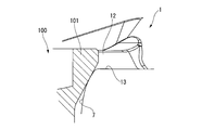
- the conventional clamp screw 100 shown in FIGS. 16 and 17 chips flowing on the polygonal surface 3 are exposed to the outside from the mounting hole 7 in the head 101 of the clamp screw 100. When it hits the part, the direction is suddenly changed or caught, and the chips do not flow smoothly, and there is a possibility that the chips are clogged.
- the clamp screw 20 of the present embodiment shown in FIGS. 13 to 15 when the chip hits the head 22 of the clamp screw 20, the chip guide portion 23 formed on the head 22 is not affected. As guided, it is discharged quickly and smoothly from the polygonal surface 3 to prevent clogging of chips.
- the insert body 2 of the cutting insert 1 has a rectangular plate shape, and the polygonal surface 3 is formed in a rectangular shape corresponding to this, and the polygonal surface 3 has a cutting edge.
- the insert body 2 of the cutting insert 1 only needs to have a polygonal plate shape.
- the shape of the polygonal surface 3 is, for example, a triangular surface shape, a pentagonal surface shape, a hexagonal surface shape, a heptagonal surface shape, an octagonal surface shape, etc. Also good.
- the number of sets of cutting edges 5 formed on the polygonal surface 3 may be other than the above-described four, for example, three, five, six, seven, eight, or the like.
- the number of ridges 12, seats 13, and breakers 14 may be changed as appropriate in correspondence with the number of sets of cutting edges 5 or regardless of the number of sets of cutting edges 5.
- the shape and arrangement of the main cutting edge 8, the sub cutting edge 9 and the corner edge 10 constituting the cutting edge 5 of the cutting insert 1 are not limited to those described in the above-described embodiment. Further, the shape and arrangement of the breaker 14 are not limited to those described in the above embodiment.
Landscapes
- Engineering & Computer Science (AREA)
- Mechanical Engineering (AREA)
- Milling Processes (AREA)
Abstract
インサート本体の剛性を確保しつつ、着座安定性を高めて加工精度を向上でき、かつ、切屑の擦過による未使用刃の損傷を防止して工具寿命を延長できること。 刃先交換式切削工具の工具本体に形成されたインサート取付座に着脱可能に装着される切削インサート1であって、多角形板状をなし、表裏反転対称形状とされたインサート本体2と、前記インサート本体2の厚さ方向を向く一対の多角形面3と、前記インサート本体2の厚さ方向に垂直な方向を向く複数の側面4と、前記多角形面3と前記側面4との交差稜線に形成された切れ刃5と、を備え、前記多角形面3には、前記切れ刃5の副切れ刃9から該多角形面3の中心部に向かうように延びる尾根部12と、前記尾根部12に隣接配置され、該尾根部12よりも前記厚さ方向に沿うインサート内側に後退させられた着座部13と、が形成されていることを特徴とする。
Description
本発明は、例えばフライス加工に用いられる切削インサート、及びこれを用いた刃先交換式切削工具に関するものである。
従来、金属材料等からなる被削材にフライス加工を施すフライスカッタ等の刃先交換式切削工具が知られている。刃先交換式切削工具は、鋼材等からなり円盤状をなす工具本体と、超硬合金等の硬質材料からなり、工具本体の先端外周部に周方向に間隔をあけて複数形成されたインサート取付座に着脱可能に装着される切削インサートと、を備えている。
また、切削インサートとしては、例えば下記特許文献1に示されるような、多角形板状をなし、表裏反転対称形状とされたインサート本体と、前記インサート本体の厚さ方向を向く一対の多角形面と、前記インサート本体の厚さ方向に垂直な方向を向く複数の側面と、前記多角形面と前記側面との交差稜線に形成された切れ刃と、を備えたものが知られている。このような両面タイプの切削インサートは、インサート本体が表裏反転対称形状とされていることで、切れ刃の数を多く確保できることから、切削インサートが長寿命化される。
ところで、上記従来の切削インサートでは、工具本体が工具軸線回りに回転されることで、該切削インサートの一対の多角形面のうち、工具回転方向の前方を向く一方の多角形面における外周縁部の切れ刃が切削に供され、他方の多角形面に形成された着座部が、該工具本体のインサート取付座に着座される。
この切削インサートを用いた切削時において、ビビリ振動などを抑制して加工精度(加工面品位や寸法精度)を高めるためには、切削インサートに作用する切削負荷によるモーメントを低減させることが好ましい。これを目的として、例えば、前記他方の多角形面の着座部から、前記一方の多角形面の切れ刃までの距離Lを短くすることが考えられる(図9及び図14の符号Lを参照)。
この切削インサートを用いた切削時において、ビビリ振動などを抑制して加工精度(加工面品位や寸法精度)を高めるためには、切削インサートに作用する切削負荷によるモーメントを低減させることが好ましい。これを目的として、例えば、前記他方の多角形面の着座部から、前記一方の多角形面の切れ刃までの距離Lを短くすることが考えられる(図9及び図14の符号Lを参照)。
この距離Lを短くするには、着座部の高さを低くすればよい。つまり、インサート本体の厚さ方向に沿う着座部の位置を、前記厚さ方向に沿うインサート内側に向けて後退させることで、該着座部と、切削に供される切れ刃との距離Lを短くすることができる。これにより、切削負荷によるモーメントが低減されるとともに、インサート取付座に対する切削インサートの着座安定性が高められて、ビビリ振動が抑制され、加工精度を向上させることができる。
しかしながら、この場合、下記の課題が生じる。
すなわち、表裏反転対称形状とされた両面タイプの切削インサートにおいては、前記他方の多角形面の着座部の高さを低くすれば、前記一方の多角形面の着座部の高さも同様に低くなるため、一方の多角形面の切れ刃が切削して生じた切屑が、該一方の多角形面における高さの低い着座部に迎え入れられやすくなるとともに、この多角形面上を流れて早期には排出されにくくなり、切削に供されていない他の切れ刃(未使用刃)に到達しやすくなる。つまり、一方の多角形面において切削に供されていない未使用刃が、切屑によって擦過されやすくなって、未使用刃が損傷するおそれがあった。さらに、単純に着座部の高さを低くした場合には、インサート本体の剛性が低減するおそれもある。
すなわち、表裏反転対称形状とされた両面タイプの切削インサートにおいては、前記他方の多角形面の着座部の高さを低くすれば、前記一方の多角形面の着座部の高さも同様に低くなるため、一方の多角形面の切れ刃が切削して生じた切屑が、該一方の多角形面における高さの低い着座部に迎え入れられやすくなるとともに、この多角形面上を流れて早期には排出されにくくなり、切削に供されていない他の切れ刃(未使用刃)に到達しやすくなる。つまり、一方の多角形面において切削に供されていない未使用刃が、切屑によって擦過されやすくなって、未使用刃が損傷するおそれがあった。さらに、単純に着座部の高さを低くした場合には、インサート本体の剛性が低減するおそれもある。
本発明は、このような事情に鑑みてなされたものであって、インサート本体の剛性を確保しつつ、着座安定性を高めて加工精度を向上でき、かつ、切屑の擦過による未使用刃の損傷を防止して工具寿命を延長できる切削インサート、及びこれを用いた刃先交換式切削工具を提供することを目的としている。
前記目的を達成するために、本発明は以下の手段を提案している。
すなわち、本発明は、刃先交換式切削工具の工具本体に形成されたインサート取付座に着脱可能に装着される切削インサートであって、多角形板状をなし、表裏反転対称形状とされたインサート本体と、前記インサート本体の厚さ方向を向く一対の多角形面と、前記インサート本体の厚さ方向に垂直な方向を向く複数の側面と、前記多角形面と前記側面との交差稜線に形成された切れ刃と、を備え、前記切れ刃は、主切れ刃と、前記多角形面を正面に見て、前記主切れ刃との間に鈍角を形成するように延びる仕上げ加工用の副切れ刃と、を有し、前記多角形面には、前記副切れ刃から該多角形面の中心部に向かうように延びる尾根部と、前記尾根部に隣接配置され、該尾根部よりも前記厚さ方向に沿うインサート内側に後退させられた着座部と、が形成されていることを特徴とする。
すなわち、本発明は、刃先交換式切削工具の工具本体に形成されたインサート取付座に着脱可能に装着される切削インサートであって、多角形板状をなし、表裏反転対称形状とされたインサート本体と、前記インサート本体の厚さ方向を向く一対の多角形面と、前記インサート本体の厚さ方向に垂直な方向を向く複数の側面と、前記多角形面と前記側面との交差稜線に形成された切れ刃と、を備え、前記切れ刃は、主切れ刃と、前記多角形面を正面に見て、前記主切れ刃との間に鈍角を形成するように延びる仕上げ加工用の副切れ刃と、を有し、前記多角形面には、前記副切れ刃から該多角形面の中心部に向かうように延びる尾根部と、前記尾根部に隣接配置され、該尾根部よりも前記厚さ方向に沿うインサート内側に後退させられた着座部と、が形成されていることを特徴とする。
本発明の切削インサートでは、インサート本体の一対の多角形面には、切れ刃の副切れ刃から該多角形面の中心部に向かうように尾根部が延設されており、着座部は、該尾根部よりも後退させられている。この切削インサートを工具本体のインサート取付座に装着すると、一対の多角形面のうち、一方の多角形面の切れ刃が切削に供され、他方の多角形面の着座部がインサート取付座に着座させられるが、該着座部の高さが低くなっている(尾根部よりインサート本体の厚さ方向に沿うインサート内側に後退させられている)ことで、前記一方の多角形面において切削に供される切れ刃からインサート取付座までの距離が短くなる。これにより、切削インサートに作用する切削負荷によるモーメントが低減され、切削インサートの着座安定性が高められるとともに、ビビリ振動などが抑制され、切削の加工精度を向上させることができる。
また、切れ刃が被削材を切削して生じた切屑は、該切れ刃から前記一方の多角形面上を流れていき、尾根部に当てられることにより、この多角形面上から早期に排出されるようになっている。これにより、例えば切屑が、切削に供される切れ刃から前記一方の多角形面上を流れていき、他の切れ刃(未使用刃)に到達するようなことが効果的に防止される。従って、未使用刃の損傷を防止でき、工具寿命を延長することができる。
さらに、多角形面に尾根部が延設されていることで、該尾根部が梁のように作用して、インサート本体の剛性が確保される。
特に本発明では、多角形面の尾根部が、該多角形面における外周縁部の副切れ刃から中心部に向けて延設されており、上記梁の作用効果が顕著に得られるとともに、該副切れ刃の刃先強度も確保される。すなわち、切れ刃のうち、仕上げ加工用のさらい刃(仕上げ刃)である副切れ刃は、主切れ刃に比べて刃先が鋭利で比較的欠損しやすいが、本発明では該副切れ刃の剛性が尾根部によって確保されるため、該副切れ刃の刃先強度が高められているとともに欠損やチッピングが抑制されて、被削材の加工面精度が高品位に安定して維持される。
特に本発明では、多角形面の尾根部が、該多角形面における外周縁部の副切れ刃から中心部に向けて延設されており、上記梁の作用効果が顕著に得られるとともに、該副切れ刃の刃先強度も確保される。すなわち、切れ刃のうち、仕上げ加工用のさらい刃(仕上げ刃)である副切れ刃は、主切れ刃に比べて刃先が鋭利で比較的欠損しやすいが、本発明では該副切れ刃の剛性が尾根部によって確保されるため、該副切れ刃の刃先強度が高められているとともに欠損やチッピングが抑制されて、被削材の加工面精度が高品位に安定して維持される。
このように、本発明の切削インサートによれば、インサート本体の剛性を確保しつつ、着座安定性を高めて加工精度を向上でき、かつ、切屑の擦過による未使用刃の損傷を防止して工具寿命を延長できるのである。
また、本発明の切削インサートにおいて、前記多角形面における前記着座部と前記切れ刃との間には、該切れ刃に沿うように延びるブレーカが形成されており、前記ブレーカは、少なくともその一部以上が前記着座部よりも前記厚さ方向に沿うインサート内側に後退させられていることとしてもよい。
この場合、着座部よりも後退させられたブレーカ部分によって切屑がカールさせられやすくなるとともに、早期に多角形面上から排出されやすくなって、切屑が着座部に擦過したり溶着したりするようなことが抑制される。これにより、この切削インサートを反転させて、工具本体のインサート取付座に前記着座部を着座させた際における該切削インサートの着座安定性が十分に確保されて、前述の効果がより顕著に得られることとなる。
また、本発明の切削インサートにおいて、前記切れ刃の前記主切れ刃は、該主切れ刃に隣接する前記副切れ刃とは反対側に向かうに従い漸次前記厚さ方向に沿うインサート内側に向かって傾斜して延びていることとしてもよい。
この場合、切削インサートが、両面タイプのネガティブインサートでありながらも、主切れ刃のアキシャルレーキ角を容易にポジ角に設定することができ、該主切れ刃の切れ味が高められる。その一方で、このように傾斜して形成された主切れ刃が切削して生じた切屑は、従来の構成では未使用刃に流れやすかった。本発明によれば、主切れ刃が前述のように傾斜して形成されていても、尾根部という特別な構成を採用したことによって、切屑が未使用刃に流れることを効果的に抑制できる。
また、本発明は、円盤状をなし、工具軸線回りに回転され、その先端外周部に前記インサート取付座が複数形成された工具本体と、前記インサート取付座に着脱可能に装着される、前述した切削インサートと、前記切削インサートの前記インサート本体を前記厚さ方向に貫通して前記一対の多角形面の中心部に開口された取付孔に挿通されるとともに、前記インサート取付座にねじ込まれることにより、該切削インサートを前記工具本体に固定するクランプネジと、を備えた刃先交換式切削工具であって、前記クランプネジは、ネジ軸部と、前記ネジ軸部より大径の頭部と、を有し、前記頭部のうち、前記ネジ軸部とは反対側に位置するとともに前記切削インサートの前記取付孔から外部に露出される部位には、このクランプネジの縦断面視で、前記取付孔の中心軸に沿って前記ネジ軸部から離間するに従い漸次前記中心軸に向けて傾斜して延びる切屑案内部が形成されていることを特徴とする。
本発明の刃先交換式切削工具に用いられるクランプネジには、その頭部に切屑案内部が形成されているので、切削に供される切れ刃から多角形面上を流れる切屑が、該頭部に当たってもスムースに排出されやすくなって、切屑詰まりが防止される。
具体的に、従来のクランプネジを用いた場合、多角形面上を流れる切屑が、該クランプネジの頭部に当たることで急激に向きを変えられたり引っ掛かったりして、切屑がスムースに流れなくなり、切屑詰まりが生じるおそれがあった。
一方、本発明によれば、切屑が、クランプネジの頭部に当たった際、該クランプネジの頭部に形成された切屑案内部に案内されるように、早期にかつスムースに多角形面上から排出されて、切屑詰まりが防止される。
具体的に、従来のクランプネジを用いた場合、多角形面上を流れる切屑が、該クランプネジの頭部に当たることで急激に向きを変えられたり引っ掛かったりして、切屑がスムースに流れなくなり、切屑詰まりが生じるおそれがあった。
一方、本発明によれば、切屑が、クランプネジの頭部に当たった際、該クランプネジの頭部に形成された切屑案内部に案内されるように、早期にかつスムースに多角形面上から排出されて、切屑詰まりが防止される。
本発明の切削インサート及び刃先交換式切削工具によれば、インサート本体の剛性を確保しつつ、着座安定性を高めて加工精度を向上でき、かつ、切屑の擦過による未使用刃の損傷を防止して工具寿命を延長することができる。
1 切削インサート
2 インサート本体
3 多角形面
4 側面
5 切れ刃
7 取付孔
8 主切れ刃
9 副切れ刃
12 尾根部
13 着座部
14 ブレーカ
20 クランプネジ
21 ネジ軸部
22 頭部
23 切屑案内部
30 刃先交換式切削工具
31 工具本体
32 インサート取付座
O1 工具軸線
O2 インサート軸線(取付孔の中心軸)
2 インサート本体
3 多角形面
4 側面
5 切れ刃
7 取付孔
8 主切れ刃
9 副切れ刃
12 尾根部
13 着座部
14 ブレーカ
20 クランプネジ
21 ネジ軸部
22 頭部
23 切屑案内部
30 刃先交換式切削工具
31 工具本体
32 インサート取付座
O1 工具軸線
O2 インサート軸線(取付孔の中心軸)
以下、本発明の一実施形態に係る切削インサート1及びこれを用いた刃先交換式切削工具30について、図面を参照して説明する。
本実施形態の切削インサート1は、金属材料等からなる被削材にフライス加工等を施すものであり、該切削インサート1を用いた刃先交換式切削工具30は、例えばフライスカッタである。
本実施形態の切削インサート1は、金属材料等からなる被削材にフライス加工等を施すものであり、該切削インサート1を用いた刃先交換式切削工具30は、例えばフライスカッタである。
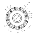
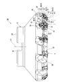
図1~図3に示されるように、刃先交換式切削工具30は、鋼材等からなる円盤状をなし、工具軸線O1回りに回転され、その先端外周部にインサート取付座32が周方向に間隔をあけて複数形成された工具本体31と、超硬合金等の硬質材料からなり、インサート取付座32に着脱可能に装着される複数の切削インサート1と、鋼材等からなり、切削インサート1の後述する取付孔7に挿通されるとともに、インサート取付座32にねじ込まれることにより、該切削インサート1を工具本体31に固定するクランプネジ20と、を備えている。
切削インサート1は、インサート取付座32に螺着されたクランプネジ20のねじ込みを緩めて該クランプネジ20をインサート取付座32から取り外すことで、工具本体31から取り外し可能となっている。このように、切削インサート1は工具本体31のインサート取付座32に対して着脱可能である。
切削インサート1は、インサート取付座32に螺着されたクランプネジ20のねじ込みを緩めて該クランプネジ20をインサート取付座32から取り外すことで、工具本体31から取り外し可能となっている。このように、切削インサート1は工具本体31のインサート取付座32に対して着脱可能である。
工具本体31は、工具軸線O1を中心とした円盤状(円柱状を含む)をなしている。工具本体31には、工具軸線O1に沿って延びる工具取付孔33が該工具本体31を貫通して形成されている。また、工具本体31において工具軸線O1方向に沿う基端側(図3における上側)を向く端面34には、工具取付孔33の開口縁部から径方向外側に向けて延びるキー溝35が形成されている。工具本体31は、キー溝35を工作機械(不図示)の主軸先端部に設けられたキーに嵌合させた状態で、工具取付孔33に挿通されるボルト部材によって該主軸先端部に取り付けられ、工具軸線O1回りの工具回転方向Tに回転させられて、被削材の切削加工に供される。
尚、本明細書では、工具回転方向Tに沿う方向を工具回転方向Tの前方といい、これとは反対側へ向かう方向(反工具回転方向)を工具回転方向Tの後方という。
尚、本明細書では、工具回転方向Tに沿う方向を工具回転方向Tの前方といい、これとは反対側へ向かう方向(反工具回転方向)を工具回転方向Tの後方という。
工具本体31において工具軸線O1方向に沿う先端側(図3における下側)の端部には、該工具本体31の外面が切り欠かれるように先端側及び径方向外側に向けて開口されたチップポケット36が形成されている。チップポケット36は、工具本体31の先端外周部に、周方向に間隔を開けて複数形成されている。
また、チップポケット36には、該チップポケット36における工具回転方向Tの後方の端部に位置するとともに、工具回転方向Tの前方を向くインサート取付座32が形成されている。チップポケット36には、そのインサート取付座32に装着される切削インサート1の切れ刃5に向けて開口するように、クーラント供給孔が形成されている。インサート取付座32は、チップポケット36において工具回転方向Tの前方を向く壁面に、切削インサート1の形状に対応するように凹状に形成されている。
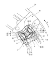
図5に示されるように、インサート取付座32は、多角形板状をなす切削インサート1の形状に対応して、多角形穴状に形成されている。尚、インサート取付座32は、切削インサート1の後述する着座部13が着座可能な形状とされていればよく、その形状は前記多角形穴状に限定されない。このインサート取付座32は、切削インサート1の後述する着座部13に当接される底壁37と、切削インサート1の側面4に当接される一対の側壁38と、を備えている。
底壁37には、クランプネジ20が螺着可能に穿設された雌ネジ孔39と、切削インサート1の後述する尾根部12に対応して溝状をなす複数の凹部40と、が形成されている。図5において、雌ネジ孔39は、底壁37の中央に配置されており、複数の凹部40は、雌ネジ孔39を中心としてX字状に延びて形成されている。
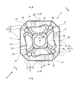
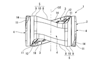
図6~図12に示されるように、切削インサート1は、多角形板状をなし、表裏反転対称形状とされたインサート本体2と、インサート本体2の厚さ方向を向く一対の多角形面3と、インサート本体2の厚さ方向に垂直な方向を向く複数の側面4と、多角形面3と側面4との交差稜線に形成された切れ刃5と、を備えている。
この切削インサート1は、所謂、両面タイプのネガティブインサートである。
この切削インサート1は、所謂、両面タイプのネガティブインサートである。
具体的に、本実施形態のインサート本体2は、四角形板状をなしており、一対の多角形面3は、それぞれ四角形面状に形成されている。インサート本体2には、該インサート本体2を厚さ方向に貫通して一対の多角形面3の中心部に開口された取付孔7が形成されている。図9に示されるように、取付孔7の開口部(前記厚さ方向に沿う両端部)は、該開口部以外の部位より大径とされているとともに、インサート本体2の厚さ方向に沿うインサート外側へ向かうに従い漸次拡径している。
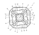
図7に示される上面視で、切削インサート1は、取付孔7の中心軸を中心とした90°回転対称形状とされている。すなわち、取付孔7の中心軸は、切削インサート1の中心軸線と同軸とされており、本明細書では、この中心軸を前述の工具軸線O1とは区別して、インサート軸線O2という。
また、図7において、インサート本体2は、インサート軸線O2に直交して側面4の中心を通る対称線O3に関して、180°回転対称形状とされており、これにより、該インサート本体2及び切削インサート1は、表裏反転対称形状となっている。
また、図7において、インサート本体2は、インサート軸線O2に直交して側面4の中心を通る対称線O3に関して、180°回転対称形状とされており、これにより、該インサート本体2及び切削インサート1は、表裏反転対称形状となっている。
図6~図8において、多角形面3の外周縁部には、複数の切れ刃5が形成されている。本実施形態では、多角形面3が4つの辺部と4つの隅部とを有する四角形面状に形成されており、より詳しくは、多角形面3は、上記辺部を構成する4つの長辺と、上記隅部を構成する4つの短辺及び8つの角部とを有しており、厳密には八角形面状に形成されていて、1つの長辺(後述する主切れ刃8)と1つの短辺(後述する副切れ刃9)とを備える一組の切れ刃5が、多角形面3の周方向に沿って4つ(4組)配置されている。尚、前記周方向とは、インサート軸線O2回りに周回する方向である。
切れ刃5は、多角形面3の外周縁部のうち、前記長辺に対応する領域(辺部)に形成されるとともに、主たる切削に用いられる主切れ刃8と、前記短辺に対応する領域(隅部)に形成されるとともに、この多角形面3を正面に見て、主切れ刃8との間に鈍角を形成するように延びる仕上げ加工用の副切れ刃(さらい刃)9と、前記長辺と前記短辺とが交差する角部に対応する領域(隅部)に形成されるとともに、主切れ刃8及び副切れ刃9を滑らかに繋ぐ曲線状のコーナー刃10と、を有している。
尚、コーナー刃10は設けられていなくても構わない。
尚、コーナー刃10は設けられていなくても構わない。
図8に示される側面視で、切れ刃5の主切れ刃8は、該主切れ刃8に隣接する副切れ刃9(本実施形態では、該主切れ刃8にコーナー刃10を挟んで隣接する副切れ刃9)とは反対側に向かうに従い漸次インサート本体2の厚さ方向(図8における上下方向)に沿うインサート内側に向かって傾斜して延びている。また、図12に示される側面視で、切れ刃5の副切れ刃9は、該副切れ刃9に隣接する主切れ刃8(本実施形態では、該副切れ刃9にコーナー刃10を挟んで隣接する主切れ刃8)とは反対側に向かうに従い漸次インサート本体2の厚さ方向(図12における上下方向)に沿うインサート内側に向かって僅かに傾斜して延びている。また、コーナー刃10は、図8や図12に示される側面視、及び、図7に示される上面視においても、それぞれ凸曲線状をなしている。
また、図4に示されるように、多角形面3において周方向に隣り合う一対(2組)の切れ刃5のうち、一の切れ刃5Aにおける主切れ刃8と、他の切れ刃5Bにおける副切れ刃9とは、連結刃11により滑らかに接続されている。連結刃11は、刃長の長い凹曲線部分と、刃長の短い凸曲線部分とを有しており、全体としては凹曲線状をなしている。連結刃11は、被削材に切り込まれる刃ではないことから、設けられていなくても構わない。
そして、図6及び図7に示されるように、多角形面3には、切れ刃5の副切れ刃9から該多角形面3の中心部に向かうように延びる尾根部12と、尾根部12に隣接配置され、該尾根部12よりもインサート本体2の厚さ方向に沿うインサート内側に後退させられた着座部13と、切れ刃5に沿うように延びるブレーカ14と、が形成されている。
図7に示される上面視で、尾根部12は、多角形面3の外周縁部のうち前記短辺に位置する副切れ刃9から、該多角形面3において中心部に位置する取付孔7に向かうように、インサート軸線O2に対して直交するように延びている。すなわち、尾根部12は、多角形面3の外周縁部における前記短辺と、該多角形面3の中心部との間に延設されており、本実施形態では、多角形面3の4つの前記短辺に対応して、4つの尾根部12がインサート軸線O2を中心とした放射状をなすように形成されている。また、尾根部12における上端面(インサート本体2の厚さ方向に沿うインサート外側を向く端面)の幅(多角形面3の周方向に沿う長さ)は、多角形面3の前記短辺近傍が最も広くされており、該短辺近傍から中心部に向かうに従い漸次狭くなっている。一方、尾根部12における底部の幅は、該尾根部12が延設される方向に沿って略一定となっている。
図9及び図10において、尾根部12の高さ(インサート本体2の厚さ方向に沿う長さ)は、該尾根部12が延設される方向に沿う中央部において略一定とされ、該中央部より多角形面3の前記短辺側に位置する部分でこの中央部より高くされ、該中央部より多角形面3の中心部側に位置する部分でこの中央部より低くなっている。尚、尾根部12において取付孔7に臨む内側端部(前記中央部より多角形面3の中心部側に位置する端部)は、この取付孔7にクランプネジ20が挿通された際、該取付孔7の開口部より先にクランプネジ20の頭部22に当接しないように配置されている。これにより、クランプネジ20の頭部22が取付孔7の開口部全周に亘って当接され、摩擦抵抗が高められるとともに締め付け力が確保されて、該クランプネジ20が容易に緩むようなことが防止される。
また、尾根部12の高さは、その周方向に隣接する着座部13側に向かうに従い漸次低くされていて、これにより尾根部12の側面は傾斜面となっている。また、尾根部12の幅は、インサート本体2の厚さ方向に沿うインサート内側に向かうに従い漸次広くなっている。
図6及び図7に示されるように、着座部13は、多角形面3において周方向に隣り合う尾根部12同士の間に形成されている。本実施形態では、着座部13は、インサート軸線O2に垂直な平坦状(平面状)とされている。着座部13は、この切削インサート1が装着されるインサート取付座32の底壁37において、隣り合う凹部40同士の間に形成された三角形面状の平坦部分(図5を参照)に対応して、三角形状又は台形状をなしている。
図6及び図7において、ブレーカ14は、多角形面3における切れ刃5の内側に、該切れ刃5に隣接して形成されている。ブレーカ14は、多角形面3における少なくとも着座部13と切れ刃5との間に形成されているとともに、該切れ刃5に沿って延びる溝状或いは傾斜面状をなしており、本実施形態においては、着座部13と切れ刃5(主切れ刃8)との間から、尾根部12と切れ刃5(副切れ刃9)との間に亘って形成されている。
図7に示される上面視で、ブレーカ14の幅は、その隣接する切れ刃5における副切れ刃9から主切れ刃8側に向かうに従い漸次又は段階的に広くなっている。図示の例では、ブレーカ14において切れ刃5の主切れ刃8に隣接する部位については、該主切れ刃8に隣接する副切れ刃9とは反対側に向かうに従い漸次その幅が広くなるように形成されている。
図9~図11に示されるように、ブレーカ14は、多角形面3の外周縁部に位置する切れ刃5から多角形面3の中心部側に向けて離間するに従い漸次インサート本体2の厚さ方向に沿うインサート内側に向かって傾斜している。また、図6、図9及び図10等に示されるように、ブレーカ14は、その隣接する切れ刃5のインサート本体2の厚さ方向に沿う位置(インサート軸線O2に沿う位置、つまり高さ)が周方向(該切れ刃5の刃長方向)に沿って変化していることに対応して、その前記高さが周方向に沿って変化している。
具体的には、ブレーカ14の高さは、その隣接する切れ刃5の副切れ刃9に対応する部分が最も高くされ、コーナー刃10から主切れ刃8側に向かうに従い漸次低くされている。そして、ブレーカ14は、少なくともその一部以上が着座部13よりもインサート本体2の厚さ方向に沿うインサート内側に後退させられている。
より詳しくは、ブレーカ14の高さは、その隣接する切れ刃5における主切れ刃8のうちその中央より該主切れ刃8に隣接する副切れ刃9側に位置する部分、前記副切れ刃9、及び、これらの間に位置するコーナー刃10に対応する領域については、着座部13の高さより高くされている。一方、ブレーカ14の高さは、主切れ刃8のうちその中央より該主切れ刃8に隣接する副切れ刃9とは反対側に位置する部分に対応する領域については、着座部13の高さより低くなっている(図10を参照)。またこれにより、ブレーカ14は、主切れ刃8のうちその中央より該主切れ刃8に隣接する副切れ刃9側に位置する部分、前記副切れ刃9、及び、これらの間に位置するコーナー刃10に対応する領域については傾斜面状をなし、前記主切れ刃8のうちその中央より該主切れ刃8に隣接する副切れ刃9とは反対側に位置する部分に対応する領域については、溝状をなしている。
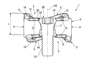
図13及び図14に示されるように、クランプネジ20は、雄ネジ加工が施されたネジ軸部21と、ネジ軸部21より大径とされた頭部22と、を有している。図14及び図15は、このクランプネジ20を用いて、切削インサート1を工具本体31のインサート取付座32に装着した状態を表している(ただしインサート取付座32は図示していない)。
クランプネジ20のネジ軸部21は、インサート取付座32の雌ネジ孔39に螺着される(図5を参照)。また、図14及び図15において、クランプネジ20の頭部22のうち、ネジ軸部21とは反対側に位置するとともに切削インサート1の取付孔7から外部に露出される部位には、このクランプネジ20の縦断面視で、取付孔7の中心軸(インサート軸線O2)に沿ってネジ軸部21から離間するに従い漸次前記中心軸に向けて傾斜して延びる切屑案内部23が形成されている。
具体的に、切屑案内部23は、クランプネジ20の頭部22においてネジ軸部21とは反対側に位置する端部に形成されている。切屑案内部23は、クランプネジ20の頭部22に溝状に形成されているとともに、周方向に沿って延びる環状をなしている。図15に示される縦断面視で、切屑案内部23は、全体として凹曲線状をなしている。また、切屑案内部23の下端部は、切削インサート1の着座部13の高さ(インサート軸線O2方向に沿う位置)に対応して配置されており、図示の例では、前記下端部の延長線上に、着座部13における内周端縁が位置するようになっている。
図4に示されるように、このクランプネジ20を用いて、切削インサート1を工具本体31のインサート取付座32に装着した状態においては、一対の多角形面3のうち、一方の多角形面3Aが、工具回転方向Tの前方を向いて配置されるとともに、すくい面とされる。また、一対の多角形面3のうち、他方の多角形面3Bが、工具回転方向Tの後方を向いて配置されるとともに、図5に示されるインサート取付座32の底壁37に着座される。
具体的に、この底壁37には、他方の多角形面3Bにおける着座部13が当接され、該着座部13に隣接する尾根部12については、底壁37の凹部40内に収容される。また、インサート取付座32の一対の側壁38には、切削インサート1の側面4がそれぞれ当接される。
具体的に、この底壁37には、他方の多角形面3Bにおける着座部13が当接され、該着座部13に隣接する尾根部12については、底壁37の凹部40内に収容される。また、インサート取付座32の一対の側壁38には、切削インサート1の側面4がそれぞれ当接される。
図4において、切削時には、工具本体31に装着された切削インサート1の複数の切れ刃5のうち、一方の多角形面3A(すくい面)において工具本体31の先端側かつ工具径方向外側に配置された一組の切れ刃5Aが、切削に供されることになる。また、この切れ刃5Aに隣接する側面4が、逃げ面とされる。本実施形態においては、切削インサート1の側面4には、互いに傾斜が異なる1番逃げ面と2番逃げ面とが、切れ刃5(図示の例では主切れ刃8及びコーナー刃10)からこの順に形成されている。
以上説明した本実施形態の切削インサート1では、インサート本体2の一対の多角形面3には、切れ刃5の副切れ刃9から該多角形面3の中心部に向かうように尾根部12が延設されており、着座部13は、該尾根部12よりも後退させられている。図4に示されるように、この切削インサート1を工具本体31のインサート取付座32に装着すると、一対の多角形面3のうち、一方の多角形面3Aの切れ刃5Aが切削に供され、他方の多角形面3Bの着座部13がインサート取付座32に着座させられるが、該着座部13の高さが低くなっている(尾根部12よりインサート本体2の厚さ方向に沿うインサート内側に後退させられている)ことで、一方の多角形面3Aにおいて切削に供される切れ刃5Aからインサート取付座32まで(つまり切れ刃5Aから他方の多角形面3Bの着座部13まで)の距離Lが短くなる(図9及び図14を参照)。これにより、切削インサート1に作用する切削負荷によるモーメントが低減され、切削インサート1の着座安定性が高められるとともに、ビビリ振動などが抑制され、切削の加工精度を向上させることができる。
また、図4において切れ刃5Aが被削材を切削して生じた切屑は、該切れ刃5Aから一方の多角形面3A上を流れていき、尾根部12に当てられることにより、この多角形面3A上から早期に排出されるようになっている。これにより、例えば切屑が、切削に供される切れ刃5Aから一方の多角形面3A上を流れていき、他の切れ刃5B(未使用刃)に到達するようなことが効果的に防止される。従って、未使用刃の損傷を防止でき、工具寿命を延長することができる。
尚、本実施形態においては、多角形面3には、着座部13を該多角形面3の周方向から挟むように一対の尾根部12が形成されており、該一対の尾根部12のうち、周方向に隣り合う切れ刃5A、5B間に位置する尾根部12によって、切れ刃5Aで切削し生じた切屑が該切れ刃5Aの工具軸線O1の基端側(図3における上側)に位置する切れ刃5Bに到達することが防止され、かつ、周方向に隣り合う切れ刃5A、5C間に位置する尾根部12によって、該切れ刃5Aの工具径方向内側(図3における切れ刃5Aの左側)に位置する切れ刃5Cに切屑が到達することも防止されている。
尚、本実施形態においては、多角形面3には、着座部13を該多角形面3の周方向から挟むように一対の尾根部12が形成されており、該一対の尾根部12のうち、周方向に隣り合う切れ刃5A、5B間に位置する尾根部12によって、切れ刃5Aで切削し生じた切屑が該切れ刃5Aの工具軸線O1の基端側(図3における上側)に位置する切れ刃5Bに到達することが防止され、かつ、周方向に隣り合う切れ刃5A、5C間に位置する尾根部12によって、該切れ刃5Aの工具径方向内側(図3における切れ刃5Aの左側)に位置する切れ刃5Cに切屑が到達することも防止されている。
さらに、多角形面3に尾根部12が延設されていることで、該尾根部12が梁のように作用して、インサート本体2の剛性が確保される。特に本実施形態では、尾根部12が多角形面3の前記短辺(副切れ刃9)から中心部に向かうように延びていることで、この効果が顕著に得られるようになっている。
また、多角形面3の尾根部12が、副切れ刃9から中心部に向けて延設されていることで、該副切れ刃9の刃先強度が確保される。すなわち、切れ刃5のうち、仕上げ加工用のさらい刃(仕上げ刃)である副切れ刃9は、主切れ刃8に比べて刃先が鋭利で比較的欠損しやすいが、本実施形態では該副切れ刃9の剛性が尾根部12によって確保されるため、該副切れ刃9の刃先強度が高められているとともに欠損やチッピングが抑制されて、被削材の加工面精度が高品位に安定して維持される。
具体的に、本実施形態では、尾根部12における上端面の幅が、多角形面3の前記短辺近傍(つまり副切れ刃9近傍)において最も広くされており、前述の効果が顕著に得られるようになっている。その一方、尾根部12における底部の幅は、該尾根部12が延設される方向に沿って略一定となっており、この尾根部12によってインサート本体2の剛性を高める効果が確保されている。
このように、本実施形態の切削インサート1によれば、インサート本体2の剛性を確保しつつ、着座安定性を高めて加工精度を向上でき、かつ、切屑の擦過による未使用刃の損傷を防止して工具寿命を延長できるのである。
また、多角形面3において切れ刃5と着座部13との間に位置し該切れ刃5に沿うように延びるブレーカ14が、少なくともその一部以上が着座部13よりもインサート本体2の厚さ方向に沿うインサート内側に後退させられているので、下記の効果を奏する。
すなわち、このように着座部13よりも後退させられたブレーカ14部分によって切屑がカールさせられやすくなるとともに、早期に多角形面3上から排出されやすくなって、切屑が着座部13に擦過したり溶着したりするようなことが抑制される。これにより、この切削インサート1を反転させて、工具本体31のインサート取付座32に前記着座部13を着座させた際における該切削インサート1の着座安定性が十分に確保されて、前述の効果がより顕著に得られることとなる。
すなわち、このように着座部13よりも後退させられたブレーカ14部分によって切屑がカールさせられやすくなるとともに、早期に多角形面3上から排出されやすくなって、切屑が着座部13に擦過したり溶着したりするようなことが抑制される。これにより、この切削インサート1を反転させて、工具本体31のインサート取付座32に前記着座部13を着座させた際における該切削インサート1の着座安定性が十分に確保されて、前述の効果がより顕著に得られることとなる。
また、切れ刃5の主切れ刃8は、該主切れ刃8に隣接する副切れ刃9とは反対側に向かうに従い漸次インサート本体2の厚さ方向に沿うインサート内側に向かって傾斜して延びているので、下記の効果を奏する。
すなわち、切削インサート1が、両面タイプのネガティブインサートとされながらも、主切れ刃8のアキシャルレーキ角を容易にポジ角に設定することができ、該主切れ刃8の切れ味が高められる。その一方で、このように傾斜して形成された主切れ刃8が切削して生じた切屑は、従来の構成では未使用刃に流れやすかった。本実施形態によれば、主切れ刃8が前述のように傾斜して形成されていても、尾根部12という特別な構成を採用したことによって、切屑が未使用刃に流れることを効果的に抑制できる。
すなわち、切削インサート1が、両面タイプのネガティブインサートとされながらも、主切れ刃8のアキシャルレーキ角を容易にポジ角に設定することができ、該主切れ刃8の切れ味が高められる。その一方で、このように傾斜して形成された主切れ刃8が切削して生じた切屑は、従来の構成では未使用刃に流れやすかった。本実施形態によれば、主切れ刃8が前述のように傾斜して形成されていても、尾根部12という特別な構成を採用したことによって、切屑が未使用刃に流れることを効果的に抑制できる。
また、工具本体31のインサート取付座32に切削インサート1を固定するクランプネジ20には、その頭部22に切屑案内部23が形成されているので、切削に供される切れ刃5から多角形面3上を流れる切屑が、該頭部22に当たってもスムースに排出されやすくなって、切屑詰まりが防止される。
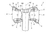
具体的に、図16及び図17に示される従来のクランプネジ100を用いた場合、多角形面3上を流れる切屑が、クランプネジ100の頭部101のうち取付孔7から外部に露出される部位に当たることで急激に向きを変えられたり引っ掛かったりして、切屑がスムースに流れなくなり、切屑詰まりが生じるおそれがあった。一方、図13~図15に示される本実施形態のクランプネジ20によれば、切屑が、該クランプネジ20の頭部22に当たった際、該頭部22に形成された切屑案内部23に案内されるように、早期にかつスムースに多角形面3上から排出されて、切屑詰まりが防止される。
具体的に、図16及び図17に示される従来のクランプネジ100を用いた場合、多角形面3上を流れる切屑が、クランプネジ100の頭部101のうち取付孔7から外部に露出される部位に当たることで急激に向きを変えられたり引っ掛かったりして、切屑がスムースに流れなくなり、切屑詰まりが生じるおそれがあった。一方、図13~図15に示される本実施形態のクランプネジ20によれば、切屑が、該クランプネジ20の頭部22に当たった際、該頭部22に形成された切屑案内部23に案内されるように、早期にかつスムースに多角形面3上から排出されて、切屑詰まりが防止される。
尚、本発明は前述の実施形態に限定されるものではなく、本発明の趣旨を逸脱しない範囲において種々の変更を加えることが可能である。
例えば、前述の実施形態では、切削インサート1のインサート本体2は四角形板状をなしており、これに対応して多角形面3は四角形面状に形成され、該多角形面3には切れ刃5の組が4つ形成されているとしたが、これに限定されるものではない。すなわち、切削インサート1のインサート本体2は、多角形板状をなしていればよく、前述した四角形板状以外の、例えば三角形板状、五角形板状、六角形板状、七角形板状、八角形板状等であってもよい。また、多角形面3の形状はこれに対応して、前述した四角形面状以外の、例えば三角形面状、五角形面状、六角形面状、七角形面状、八角形面状等であってもよい。また、多角形面3に形成される切れ刃5の組数も、前述した4つ以外の、例えば3つ、5つ、6つ、7つ、8つ等であってもよい。
また、切れ刃5の組数に対応して、或いは切れ刃5の組数に係わらず、尾根部12、着座部13及びブレーカ14の数も適宜変更してよい。
また、切れ刃5の組数に対応して、或いは切れ刃5の組数に係わらず、尾根部12、着座部13及びブレーカ14の数も適宜変更してよい。
また、切削インサート1の切れ刃5を構成する主切れ刃8、副切れ刃9及びコーナー刃10の形状や配置は、前述の実施形態で説明したものに限定されない。また、ブレーカ14の形状や配置についても、前述の実施形態で説明したものに限定されない。
その他、本発明の趣旨から逸脱しない範囲において、前述の実施形態、変形例及び尚書き等で説明した各構成(構成要素)を組み合わせてもよく、また、構成の付加、省略、置換、その他の変更が可能である。また本発明は、前述した実施形態によって限定されることはなく、特許請求の範囲によってのみ限定される。
本発明の利用により、インサート本体の剛性を確保しつつ、着座安定性を高めて加工精度を向上でき、かつ、切屑の擦過による未使用刃の損傷を防止して工具寿命を延長できる。
Claims (4)
- 刃先交換式切削工具の工具本体に形成されたインサート取付座に着脱可能に装着される切削インサートであって、
多角形板状をなし、表裏反転対称形状とされたインサート本体と、
前記インサート本体の厚さ方向を向く一対の多角形面と、
前記インサート本体の厚さ方向に垂直な方向を向く複数の側面と、
前記多角形面と前記側面との交差稜線に形成された切れ刃と、を備え、
前記切れ刃は、
主切れ刃と、
前記多角形面を正面に見て、前記主切れ刃との間に鈍角を形成するように延びる仕上げ加工用の副切れ刃と、を有し、
前記多角形面には、
前記副切れ刃から該多角形面の中心部に向かうように延びる尾根部と、
前記尾根部に隣接配置され、該尾根部よりも前記厚さ方向に沿うインサート内側に後退させられた着座部と、が形成されていることを特徴とする切削インサート。 - 請求項1に記載の切削インサートであって、
前記多角形面における前記着座部と前記切れ刃との間には、該切れ刃に沿うように延びるブレーカが形成されており、
前記ブレーカは、少なくともその一部以上が前記着座部よりも前記厚さ方向に沿うインサート内側に後退させられていることを特徴とする切削インサート。 - 請求項1又は2に記載の切削インサートであって、
前記切れ刃の前記主切れ刃は、該主切れ刃に隣接する前記副切れ刃とは反対側に向かうに従い漸次前記厚さ方向に沿うインサート内側に向かって傾斜して延びていることを特徴とする切削インサート。 - 円盤状をなし、工具軸線回りに回転され、その先端外周部に前記インサート取付座が複数形成された工具本体と、
前記インサート取付座に着脱可能に装着される、請求項1~3のいずれか一項に記載の切削インサートと、
前記切削インサートの前記インサート本体を前記厚さ方向に貫通して前記一対の多角形面の中心部に開口された取付孔に挿通されるとともに、前記インサート取付座にねじ込まれることにより、該切削インサートを前記工具本体に固定するクランプネジと、を備えた刃先交換式切削工具であって、
前記クランプネジは、
ネジ軸部と、
前記ネジ軸部より大径の頭部と、を有し、
前記頭部のうち、前記ネジ軸部とは反対側に位置するとともに前記切削インサートの前記取付孔から外部に露出される部位には、このクランプネジの縦断面視で、前記取付孔の中心軸に沿って前記ネジ軸部から離間するに従い漸次前記中心軸に向けて傾斜して延びる切屑案内部が形成されていることを特徴とする刃先交換式切削工具。
Applications Claiming Priority (2)
| Application Number | Priority Date | Filing Date | Title |
|---|---|---|---|
| JP2012-234167 | 2012-10-23 | ||
| JP2012234167A JP2014083632A (ja) | 2012-10-23 | 2012-10-23 | 切削インサート及び刃先交換式切削工具 |
Publications (1)
| Publication Number | Publication Date |
|---|---|
| WO2014065228A1 true WO2014065228A1 (ja) | 2014-05-01 |
Family
ID=50544608
Family Applications (1)
| Application Number | Title | Priority Date | Filing Date |
|---|---|---|---|
| PCT/JP2013/078434 Ceased WO2014065228A1 (ja) | 2012-10-23 | 2013-10-21 | 切削インサート及び刃先交換式切削工具 |
Country Status (2)
| Country | Link |
|---|---|
| JP (1) | JP2014083632A (ja) |
| WO (1) | WO2014065228A1 (ja) |
Cited By (3)
| Publication number | Priority date | Publication date | Assignee | Title |
|---|---|---|---|---|
| US20150117969A1 (en) * | 2013-10-29 | 2015-04-30 | Kennametal Inc. | Cutting insert and shim for heavy machining operations |
| JPWO2015182562A1 (ja) * | 2014-05-26 | 2017-04-20 | 株式会社タンガロイ | 切削インサート、ボデーおよび切削工具 |
| JP7730096B1 (ja) * | 2025-05-14 | 2025-08-27 | 株式会社タンガロイ | 切削インサートおよびこれを備えた切削工具 |
Families Citing this family (5)
| Publication number | Priority date | Publication date | Assignee | Title |
|---|---|---|---|---|
| KR102407067B1 (ko) * | 2018-06-08 | 2022-06-08 | 가부시키가이샤 몰디노 | 절삭 인서트 및 날끝 교환식 절삭 공구 |
| US11969807B2 (en) | 2020-01-15 | 2024-04-30 | Taegutec Ltd. | Insert and cutting tool assembly comprising same |
| US11583942B2 (en) | 2020-10-19 | 2023-02-21 | Iscar, Ltd. | Reversible square-shaped cutting insert and rotary cutting tool |
| US11491560B1 (en) | 2021-07-13 | 2022-11-08 | Taegutec Ltd. | Cutting insert and rotary cutting tool including same |
| EP4491311A4 (en) * | 2022-03-08 | 2026-03-18 | Moldino Tool Engineering Ltd | CUTTING INSERTS, TOOL BODY AND REPLACEABLE EDGE ROTARY CUTTING TOOL |
Citations (3)
| Publication number | Priority date | Publication date | Assignee | Title |
|---|---|---|---|---|
| JPH09295213A (ja) * | 1996-05-07 | 1997-11-18 | Mitsubishi Materials Corp | スローアウェイチップ及びスローアウェイ式カッタ |
| WO2010137663A1 (ja) * | 2009-05-28 | 2010-12-02 | 京セラ株式会社 | 切削インサートおよび切削工具ならびにそれらを用いた切削加工物の製造方法 |
| JP2011104738A (ja) * | 2009-11-19 | 2011-06-02 | Sumitomo Electric Hardmetal Corp | 刃先交換式チップ |
-
2012
- 2012-10-23 JP JP2012234167A patent/JP2014083632A/ja active Pending
-
2013
- 2013-10-21 WO PCT/JP2013/078434 patent/WO2014065228A1/ja not_active Ceased
Patent Citations (3)
| Publication number | Priority date | Publication date | Assignee | Title |
|---|---|---|---|---|
| JPH09295213A (ja) * | 1996-05-07 | 1997-11-18 | Mitsubishi Materials Corp | スローアウェイチップ及びスローアウェイ式カッタ |
| WO2010137663A1 (ja) * | 2009-05-28 | 2010-12-02 | 京セラ株式会社 | 切削インサートおよび切削工具ならびにそれらを用いた切削加工物の製造方法 |
| JP2011104738A (ja) * | 2009-11-19 | 2011-06-02 | Sumitomo Electric Hardmetal Corp | 刃先交換式チップ |
Cited By (3)
| Publication number | Priority date | Publication date | Assignee | Title |
|---|---|---|---|---|
| US20150117969A1 (en) * | 2013-10-29 | 2015-04-30 | Kennametal Inc. | Cutting insert and shim for heavy machining operations |
| JPWO2015182562A1 (ja) * | 2014-05-26 | 2017-04-20 | 株式会社タンガロイ | 切削インサート、ボデーおよび切削工具 |
| JP7730096B1 (ja) * | 2025-05-14 | 2025-08-27 | 株式会社タンガロイ | 切削インサートおよびこれを備えた切削工具 |
Also Published As
| Publication number | Publication date |
|---|---|
| JP2014083632A (ja) | 2014-05-12 |
Similar Documents
| Publication | Publication Date | Title |
|---|---|---|
| JP5007853B2 (ja) | 切削用インサートおよび刃先交換式切削工具 | |
| JP6205726B2 (ja) | 正面フライス用切削インサート及び刃先交換式正面フライス | |
| WO2014065228A1 (ja) | 切削インサート及び刃先交換式切削工具 | |
| JP5906976B2 (ja) | 切削インサートおよび刃先交換式切削工具 | |
| JP4814890B2 (ja) | 切削インサート、ミーリング工具および切削方法 | |
| WO2011046121A1 (ja) | 切削インサート及び刃先交換式回転工具 | |
| JP6287197B2 (ja) | ドリル用インサートおよび刃先交換式ドリル | |
| JP5445700B2 (ja) | 切削用インサートおよび刃先交換式切削工具 | |
| KR20120024666A (ko) | 절삭용 인서트 및 정면 밀링 커터 | |
| CN102548694A (zh) | 切削镶刀及切削工具、以及使用该切削工具的切削加工物的制造方法 | |
| JP2008229745A (ja) | 切削インサートおよびインサート着脱式転削工具 | |
| JP6869492B2 (ja) | 切削インサート | |
| WO2010147065A1 (ja) | 切削用インサートおよび刃先交換式正面フライス | |
| JP2014083667A (ja) | 切削インサートおよび刃先交換式切削工具 | |
| JP4857958B2 (ja) | 丸駒インサート着脱式切削工具および丸駒インサート | |
| JP5783025B2 (ja) | 切削インサートおよび刃先交換式エンドミル | |
| JP2010201565A (ja) | エンドミル | |
| JP6260330B2 (ja) | ワイパーインサート及び刃先交換式正面フライス | |
| JP2014083629A (ja) | 刃先交換式切削工具及びその工具本体 | |
| JP2015196203A (ja) | 刃先交換式メタルソー | |
| JP4804127B2 (ja) | スローアウェイインサートおよびそれを装着した転削工具、並びに、それらを用いた被削材の切削方法 | |
| JP5564958B2 (ja) | 刃先交換式溝入れ工具及び端面溝入れ加工方法 | |
| JP2015208835A (ja) | 刃先交換式正面フライス及びその製造方法 | |
| JP5309748B2 (ja) | インサート着脱式カッタおよび切削インサート | |
| JP4952560B2 (ja) | スローアウェイ式正面フライス |
Legal Events
| Date | Code | Title | Description |
|---|---|---|---|
| 121 | Ep: the epo has been informed by wipo that ep was designated in this application |
Ref document number: 13849707 Country of ref document: EP Kind code of ref document: A1 |
|
| NENP | Non-entry into the national phase |
Ref country code: DE |
|
| 122 | Ep: pct application non-entry in european phase |
Ref document number: 13849707 Country of ref document: EP Kind code of ref document: A1 |