WO2014065144A1 - 積繊体製造装置及び積繊体の製造方法 - Google Patents
積繊体製造装置及び積繊体の製造方法 Download PDFInfo
- Publication number
- WO2014065144A1 WO2014065144A1 PCT/JP2013/077853 JP2013077853W WO2014065144A1 WO 2014065144 A1 WO2014065144 A1 WO 2014065144A1 JP 2013077853 W JP2013077853 W JP 2013077853W WO 2014065144 A1 WO2014065144 A1 WO 2014065144A1
- Authority
- WO
- WIPO (PCT)
- Prior art keywords
- opening
- fiber
- suction
- fibers
- supply
- Prior art date
- Legal status (The legal status is an assumption and is not a legal conclusion. Google has not performed a legal analysis and makes no representation as to the accuracy of the status listed.)
- Ceased
Links
Images



Classifications
-
- A—HUMAN NECESSITIES
- A61—MEDICAL OR VETERINARY SCIENCE; HYGIENE
- A61F—FILTERS IMPLANTABLE INTO BLOOD VESSELS; PROSTHESES; DEVICES PROVIDING PATENCY TO, OR PREVENTING COLLAPSING OF, TUBULAR STRUCTURES OF THE BODY, e.g. STENTS; ORTHOPAEDIC, NURSING OR CONTRACEPTIVE DEVICES; FOMENTATION; TREATMENT OR PROTECTION OF EYES OR EARS; BANDAGES, DRESSINGS OR ABSORBENT PADS; FIRST-AID KITS
- A61F13/00—Bandages or dressings; Absorbent pads
- A61F13/15—Absorbent pads, e.g. sanitary towels, swabs or tampons for external or internal application to the body; Supporting or fastening means therefor; Tampon applicators
- A61F13/15577—Apparatus or processes for manufacturing
- A61F13/15617—Making absorbent pads from fibres or pulverulent material with or without treatment of the fibres
- A61F13/15626—Making fibrous pads without outer layers
-
- A—HUMAN NECESSITIES
- A61—MEDICAL OR VETERINARY SCIENCE; HYGIENE
- A61F—FILTERS IMPLANTABLE INTO BLOOD VESSELS; PROSTHESES; DEVICES PROVIDING PATENCY TO, OR PREVENTING COLLAPSING OF, TUBULAR STRUCTURES OF THE BODY, e.g. STENTS; ORTHOPAEDIC, NURSING OR CONTRACEPTIVE DEVICES; FOMENTATION; TREATMENT OR PROTECTION OF EYES OR EARS; BANDAGES, DRESSINGS OR ABSORBENT PADS; FIRST-AID KITS
- A61F13/00—Bandages or dressings; Absorbent pads
- A61F13/15—Absorbent pads, e.g. sanitary towels, swabs or tampons for external or internal application to the body; Supporting or fastening means therefor; Tampon applicators
- A61F13/15577—Apparatus or processes for manufacturing
- A61F13/15617—Making absorbent pads from fibres or pulverulent material with or without treatment of the fibres
- A61F13/15658—Forming continuous, e.g. composite, fibrous webs, e.g. involving the application of pulverulent material on parts thereof
-
- A—HUMAN NECESSITIES
- A61—MEDICAL OR VETERINARY SCIENCE; HYGIENE
- A61F—FILTERS IMPLANTABLE INTO BLOOD VESSELS; PROSTHESES; DEVICES PROVIDING PATENCY TO, OR PREVENTING COLLAPSING OF, TUBULAR STRUCTURES OF THE BODY, e.g. STENTS; ORTHOPAEDIC, NURSING OR CONTRACEPTIVE DEVICES; FOMENTATION; TREATMENT OR PROTECTION OF EYES OR EARS; BANDAGES, DRESSINGS OR ABSORBENT PADS; FIRST-AID KITS
- A61F13/00—Bandages or dressings; Absorbent pads
- A61F13/15—Absorbent pads, e.g. sanitary towels, swabs or tampons for external or internal application to the body; Supporting or fastening means therefor; Tampon applicators
- A61F13/53—Absorbent pads, e.g. sanitary towels, swabs or tampons for external or internal application to the body; Supporting or fastening means therefor; Tampon applicators characterised by the absorbing medium
Definitions
- the present invention relates to an apparatus for producing a piled body and a method for producing a piled body, and more specifically, a product in which a fiber layer in which only fibers are deposited and a mixed layer in which a water-absorbing polymer is dispersed in the deposited fibers are laminated.
- the present invention relates to a stacked fiber manufacturing apparatus and a stacked fiber manufacturing method for manufacturing a fiber.
- a laminated body in which a fiber layer in which only fibers are deposited and a mixed layer in which a water-absorbing polymer such as a superabsorbent polymer is dispersed in the deposited fiber is laminated. It is used for absorbent cores such as disposable diapers and sanitary napkins.
- the laminated fiber having such a laminated structure is manufactured by, for example, the stacked fiber manufacturing apparatus shown in FIGS. 4 and 5.
- FIG. 4 is a partially broken side view of the fiber stack manufacturing apparatus.
- a raw material roll 124 of sheet-like pulp material is fed out and pulverized by a pulverizer 126 to become fibers.
- the pulverized fibers flow through the ducts 136, 142, and 148 together with air, and are supplied to the rotary drums 100 and 110 from the hoods 138, 144, and 150 provided at the front ends of the ducts 136, 142, and 148. , 110 to form a stacked fiber body.
- the piled body is taken out from the rotary drums 100 and 110, transferred to the conveyors 162 and 166, and conveyed to a subsequent process.
- the fiber is supplied from the two ducts 136 and 142 to the rotating drum 100 of one of the stacked fiber manufacturing apparatuses 134.
- One duct 136 is connected to one end of a diffusion duct 176.
- An injection device 170 is connected to the other end of the diffusion duct 176, and water-absorbing polymer powder injected from the injection device 170 is supplied to the duct 136 through the diffusion duct 176 and mixed with the fibers flowing through the duct 136. .
- FIG. 5 is an enlarged cross-sectional view of one fiber stack manufacturing apparatus 134.
- the hoods 138, 144 at the front ends of the ducts 136, 142 are disposed adjacent to each other in the circumferential direction along the rotating drum 100, and the intersection 240 of the hoods 138, 144 and the outer periphery of the rotating drum 100.
- a gap 242 is provided between the surfaces.
- a fiber-concave recess 120 is formed on the outer peripheral surface of the rotating drum 100.
- the bottom surface of the stacking concave portion 120 is formed of a perforated element such as a screen.
- An inner portion surrounded by the rotating drum 100 is partitioned by a plurality of ribs 222, and vacuum chambers 224 and 226 are formed in regions 232 and 236 facing the hoods 138 and 144.
- fibers and the like supplied from the hoods 138 and 144 are adsorbed and deposited on the stacking recess 120, and a stacking body in which the fiber layer and the mixed layer are laminated is manufactured (see, for example, Patent Document 1).
- the pile manufacturing apparatus 134 is provided in each hood 138, 144 adjacent to the intersection 240 so that the fibers accumulated in the pile recess 120 are not lifted or sheared near the intersection 240. It is necessary to balance the pressure so that a differential pressure between the hoods does not occur, or to adjust the size of the gap 242 appropriately.
- the water-absorbing polymer supplied to the hood 138 may move to the adjacent hood 144 side.
- the stacking recess 120 is formed intermittently, the air flow changes in the vicinity of the intersection 240 as the stacking recess 120 moves, so that the water-absorbing polymer is moved to the adjacent hood 144 side. It is likely to move.
- the water-absorbing polymer moves to the adjacent hood 144 side, the water-absorbing polymer is mixed into the fiber layer where only the fibers are to be deposited. For this reason, it is difficult to produce an ideal pile having no water-absorbing polymer mixed in the fiber layer.
- the present invention easily and reliably manufactures a fiber stack in which a fiber layer in which only fibers are deposited and a mixed layer in which a water-absorbing polymer is dispersed in the deposited fibers are laminated.
- An object of the present invention is to provide an apparatus for manufacturing a stacked fiber body and a method for manufacturing the stacked fiber body.
- the present invention provides a piled body manufacturing apparatus configured as follows.
- the fiber stack manufacturing apparatus includes: (a) a rotary drum in which a fiber recess is formed on the outer peripheral surface, and a plurality of suction holes are formed in the bottom surface of the fiber stack recess; and (b) a first facing the fiber stack recess.
- a first supply duct that supplies fibers adsorbed to the fiber stack concave portion by suction from the suction hole, and (c) faces the fiber stack concave portion.
- a second supply duct for supplying fibers and water-absorbing polymers adsorbed in the stacking recesses by suction from the suction holes.
- the first opening and the second opening are arranged with a gap in the circumferential direction along the outer peripheral surface of the rotating drum.
- the fiber supplied from the first opening is deposited in the stacking concave portion to form the fiber layer in which only the fiber is deposited, and the fiber layer is supplied from the second opening on the fiber layer.
- the fiber and the water-absorbing polymer are deposited, a mixed layer in which the absorbent polymer is dispersed in the deposited fiber is formed, and a stacked fiber body in which the fiber layer and the mixed layer are laminated is manufactured.
- the mixed layer may be formed first, and the fiber layer may be formed on the mixed layer.
- an intermediate suction pressure sucked from the suction hole of the fiber stack concave portion faces the first opening and the second opening.
- the first suction pressure and the second suction pressure that are sucked from the suction hole of the stacking concave portion can be adjusted separately.
- the intermediate suction pressure that only needs to hold the deposit in the stacking concave portion can be adjusted separately from the first and second suction pressures for depositing fibers in the stacking concave portion. Is easy.
- the second supply duct has a supply port through which fibers are supplied from a pulverizer, and forms a single flow path communicating between the supply port and the second opening.
- the first supply duct has first and second supply ports arranged on both sides of the supply port of the second supply duct and supplied with fibers from the crusher.
- a Y-shaped flow path communicating between the supply port and the first opening is formed.
- a supply unit is provided.
- the polymer supply unit is provided on the upstream side of the supply port of the second supply duct, water absorption is achieved as compared with the case where the polymer supply unit is provided at an intermediate position in the flow path of the second supply duct.
- the functional polymer can be dispersed more uniformly.
- one flow path of the second supply duct has a smaller change in flow path and less turbulence in the flow path than the Y-shaped flow path of the first supply duct, The water-absorbing polymer can be more uniformly dispersed in the fiber than in the case where the polymer supply section is provided for the supply duct.
- the present invention provides a method for producing a piled body configured as follows.
- the method for manufacturing a piled body includes a first drum and a rotary drum in which a piled concave portion is formed on an outer peripheral surface and a plurality of suction holes are formed on a bottom surface of the piled concave portion.
- a second opening is disposed, (a) when the fiber stacking recess faces the first opening, fibers are supplied from the first opening, and the fibers are sucked from the suction holes by the suction. (B) when the stacking concave portion faces the second opening, the fiber and the water-absorbing polymer are supplied from the second opening, and the fiber and the water-absorbing polymer are Molecules are adsorbed and deposited in the stacking recesses by suction from the suction holes.
- the first opening and the second opening are arranged with a gap in the circumferential direction along the outer peripheral surface of the rotating drum.
- the water-absorbing polymer supplied from the second opening moves to a region facing the first opening. Can be prevented. Therefore, it is possible to easily and surely manufacture an ideal stacked body in which a water-absorbing polymer is not mixed in a fiber layer on which only fibers are deposited.
- the fiber supplied from the first opening and the fiber supplied from the second opening may be different.
- the suction is sucked from the suction hole, and the suction pressure
- the suction pressure can be adjusted separately from the suction pressure sucked from the suction hole when facing one opening and the second opening.
- the suction pressure at this time can be adjusted separately from the suction pressure when fibers or the like are deposited in the stacking concave portion, the suction pressure can be easily adjusted.
- the fiber supplied from the pulverizer has a main flow path connected to the pulverizer, and first and second branch flows branched from the main flow path and connected to the first and second openings, respectively. It conveys to the said 1st and 2nd opening via a path
- the water-absorbing polymer is supplied only to the second branch channel among the first and second branch channels from a polymer supply unit provided in the main channel.
- the polymer supply unit is provided in the main flow channel on the upstream side of the second branch flow channel, compared to the case where the polymer supply unit is provided at an intermediate position in the second branch flow channel, The water-absorbing polymer can be more uniformly dispersed.
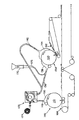
- FIG. 1 is a schematic diagram showing the configuration of the pile manufacturing apparatus 10.
- FIG. 2 is an explanatory diagram showing the configuration of the supply duct, and schematically shows a state viewed along line AA in FIG.
- the pile manufacturing apparatus 10 includes a rotating drum 20 and first and second supply ducts 30 and 40.
- the fiber outer periphery 20 s of the rotary drum 20 is formed with a stacking recess 22 that extends continuously or intermittently in the circumferential direction.
- the bottom surface of the stacking concave portion 22 is formed by a mesh member or the like, and a plurality of suction holes (not shown) are formed on the bottom surface of the stacking concave portion 22, and air is sucked from the suction holes toward the center of the rotary drum 20. It has come to be.
- the first supply duct 30 has an opening 32 at one end and first and second supply ports 34a and 34b at the other end.
- the second supply duct 40 has an opening 42 at one end and a supply port 44 at the other end.
- the first opening 32 of the first supply duct 30 and the second opening 42 of the second supply duct 40 are arranged with a gap 18 in the circumferential direction of the rotary drum 20.
- the first supply duct 30 forms a Y-shaped flow path 36 that communicates between the opening 32 and the first and second supply ports 34a and 34b.
- the second supply duct 40 forms one flow path 46 that communicates between the opening 42 and the supply port 44.
- the flow path 36 of the first supply duct 30 is a first branch flow path.
- the channel 46 of the second supply duct 40 is a second branch channel.
- the first and second supply ports 34 a and 34 b of the first supply duct 30 and the supply port 44 of the second supply duct 40 are the supply ports of the second supply duct 40.
- the first and second supply ports 34 a and 34 b of the first supply duct 30 are arranged on both sides of 44, it is connected to the fiber outlet 54 of the pulverizer 50.
- the sheet-like pulp material 2 supplied to the pulverizer 50 is pulverized by the pulverization drum 52, and the pulverized fibers are supplied from the fiber outlet 54 of the pulverizer 50 to the first and second supply ports of the first supply duct 30. 34a and 34b and the supply port 44 of the 2nd supply duct 40 are sent out. As shown by arrows 39 and 49, the delivered fibers flow along the flow paths 36 and 46 of the first and second supply ducts 30 and 40 together with the air, and are supplied to the stacking concave portion 22 of the rotary drum 20.
- a polymer supply unit 48 is provided in the main flow path 56 of the pulverizer 50 on the upstream side of the supply port 44 of the second supply duct 40.
- the polymer supply unit 48 supplies water-absorbing polymer powder from the supply port 44 of the second supply duct 40 into the flow path 46 of the second supply duct 40.
- the polymer supply section 48 is provided on the upstream side of the supply port 44 of the second supply duct 40, an intermediate position in the flow path 46 of the second supply duct 40 as shown by a two-dot chain line in FIG.
- the water-absorbing polymer can be more uniformly dispersed.
- the polymer supply unit 48 is disposed so as to face only the supply port 44 of the second supply duct 40, and the first and second supply ports 34 a and 34 b of the first supply duct 30 have a water-absorbing polymer.
- the powder is not supplied.
- the flow path 46 of the second supply duct 40 has less change in the flow path and less turbulence in the flow path. Therefore, the method of providing the polymer supply unit 48 for the second supply duct 40 makes the water-absorbing polymer more uniform in the air flow including the fibers than the case of providing the polymer supply unit for the first supply duct 30. Can be dispersed.
- the first and second openings 32 and 42 of the first and second supply ducts 30 and 40 communicate with the opposing suction holes and are connected to a vacuum source. 24 is formed.
- the pressure distribution in the suction chamber 24 can be adjusted using, for example, the flow rate adjusting dampers 26a to 26c indicated by the one-dot chain line.
- the inner portion surrounded by the rotating drum 20 can be large even if a chamber connected to a vacuum source is connected to a vacuum hole in a region other than the first and second regions 16a and 16b and the intermediate region 16c therebetween. You may open to atmospheric pressure.
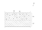
- FIG. 3 is a cross-sectional view of the fiber stack 60 manufactured by the fiber stack manufacturing apparatus 10.
- the stacked fiber body 60 includes a fiber layer 62 in which only fibers are deposited and a mixed layer 64 in which a water-absorbing polymer 66 is dispersed in the deposited fibers 65.
- the stacked fiber manufacturing apparatus 10 manufactures the stacked fiber body 60 as follows.
- Rotating drum 20 rotates in the direction indicated by arrow 28, and stacking recess 22 moves in the circumferential direction.
- the fiber stacking recess 22 reaches the first region 16 a facing the first opening 32 of the first supply duct 30, the fibers supplied from the first opening 32 are adsorbed on the bottom surface of the fiber stacking recess 22. Has been deposited. As a result, a fiber layer 62 in which only fibers are deposited is formed in the stacked fiber recess 22.
- the fiber stacking concave portion 22 moves to the intermediate region 16 c that faces the gap 18 between the first opening 32 and the second opening 42.
- the deposit (fiber layer 62) deposited in the stacking recess 22 is held in the state of being adsorbed on the bottom surface of the stacking recess 22.
- the stacking concave portion 22 reaches the second region 16b facing the second opening 42 of the second supply duct 40, the fiber and the water-absorbing polymer powder supplied from the second opening 42 Is adsorbed and deposited on the deposit (fiber layer 62) of the fiber stack recess 22.
- a mixed layer 64 in which the water-absorbing polymer is dispersed in the fiber is formed on the fiber layer 62 where only the fiber is deposited, in the stacking concave portion 22. That is, the stacked fiber body 60 is formed.
- the fiber stack 60 formed in the fiber stack recess 22 is delivered to the web 4.
- post-processing such as cutting, compression, and packaging is performed on the stacked fiber body 60 at an appropriate timing.
- the post-treatment may be performed before or after the pile 60 is transferred to the web 4.
- the gap 18 when the gap 18 is provided between the first opening 32 and the second opening 42, a part of the water-absorbing polymer supplied from the second opening 42 is in the second region. It is possible to easily and surely manufacture an ideal stacked body in which the water-absorbing polymer is not mixed in the fiber layer 62 that should be made of only fibers, while preventing movement from the 16b to the first region 16a. it can.
- suction from the suction hole is performed in the intermediate region 16c between the first region 16a and the second region 16b, the suction is performed in the intermediate region 16c, and thus the first region 16a of the water-absorbing polymer is absorbed. This is preferable because it is possible to more reliably prevent the movement.
- the stacked body manufacturing apparatus 10 can easily perform a stacked body in which a fiber layer in which only fibers are deposited and a mixed layer in which a water-absorbing polymer is dispersed in the deposited fibers are stacked. And can be manufactured reliably.
- the embodiment has been described in which the fiber layer is formed first, and the mixed layer is formed on the fiber layer.
- the present invention is not limited thereto, and the mixed layer is formed first, and the fiber layer is formed on the mixed layer. It does not matter if it is made. Also, two or more fiber layers may be formed, or two or more mixed layers may be formed.
- the thickness of the fiber layer and the mixed layer of the piled body can be increased by increasing the suction pressure of one of the dampers 26a and 26b and decreasing the suction pressure of the other.
- the basis weight may be varied.
Landscapes
- Health & Medical Sciences (AREA)
- Engineering & Computer Science (AREA)
- Vascular Medicine (AREA)
- Epidemiology (AREA)
- Biomedical Technology (AREA)
- Heart & Thoracic Surgery (AREA)
- Life Sciences & Earth Sciences (AREA)
- Animal Behavior & Ethology (AREA)
- General Health & Medical Sciences (AREA)
- Public Health (AREA)
- Veterinary Medicine (AREA)
- Manufacturing & Machinery (AREA)
- Absorbent Articles And Supports Therefor (AREA)
- Nonwoven Fabrics (AREA)
Abstract
繊維のみが堆積した繊維層と、堆積した繊維中に吸水性高分子が分散した混合層とが積層された積繊体を、容易に、かつ確実に製造することができる積繊体製造装置及び積繊体の製造方法を提供する。 回転ドラム(20)の外周面(20s)に形成された積繊凹部(22)に、第1の開口(32)から繊維が供給され、第2の開口(42)から繊維と吸水性高分子とが供給される。第1の開口(32)と第2の開口(42)とは、回転ドラム(20)の外周面(20s)に沿って周方向に隙間(18)を設けて配置される。
Description
本発明は、積繊体製造装置及び積繊体の製造方法に関し、詳しくは、繊維のみが堆積した繊維層と、堆積した繊維中に吸水性高分子が分散した混合層とが積層された積繊体を製造するための積繊体製造装置及び積繊体の製造方法に関するする。
従来、繊維のみが堆積した繊維層と、堆積した繊維中に高吸水性ポリマー(Superabsorbent Polymer)等の吸水性高分子(water-absorbing polymer)が分散した混合層とが積層された積繊体は、使い捨ておむつや生理用ナプキンなどの吸収体コア等に用いられている。このような積層構造の積繊体は、例えば図4及び図5に示す積繊体製造装置で製造される。
図4は、積繊体製造装置の一部破断側面図である。図4に示すように、シート状のパルプ材の原料ロール124が繰り出され、粉砕機126で粉砕されて繊維となる。粉砕された繊維は、空気とともにダクト136,142,148を流れ、ダクト136,142,148の先端部に設けられたフード138,144,150から、回転ドラム100,110に供給され、回転ドラム100,110に堆積して積繊体が形成される。積繊体は、回転ドラム100,110から取り出しコンベア162,166に受け渡され、後工程に搬送される。
一方の積繊体製造装置134の回転ドラム100には、2本のダクト136,142から繊維が供給される。一方のダクト136には、拡散ダクト176の一端が接続されている。拡散ダクト176の他端には噴射装置170が接続され、噴射装置170から噴射された吸水性高分子の粉末が、拡散ダクト176を通ってダクト136に供給され、ダクト136を流れる繊維と混合する。
図5は、一方の積繊体製造装置134の拡大断面図である。図5に示すように、ダクト136,142の先端部のフード138,144は、回転ドラム100に沿って周方向に互いに隣接して配置され、フード138,144の交点240と回転ドラム100の外周面との間には、隙間242が設けられている。
回転ドラム100の外周面には積繊凹部120が形成されている。積繊凹部120の底面は、スクリーン等の有孔要素で形成されている。回転ドラム100に囲まれた内側部分は、複数のリブ222で区画され、フード138,144に対向する領域232,236には、真空チャンバー224,226が形成されている。これによって、フード138,144から供給された繊維等が積繊凹部120に吸着され堆積し、繊維層と混合層とが積層された積繊体が製造される(例えば、特許文献1参照)。
図4及び図5に示した積繊体製造装置134は、積繊凹部120に堆積した繊維が交点240付近で持ち上がったりせん断されたりしないように、交点240に隣接する各フード138,144内の圧力を平衡させてフード間の差圧が生じないようにしたり、隙間242の大きさを適切に調整したりする必要がある。
また、隣接するフード138,144と回転ドラム100の外周面との間に隙間242を設けるため、フード138に供給された吸水性高分子が、隣のフード144側に移動する可能性がある。特に、積繊凹部120が間欠的に形成されていると、積繊凹部120の移動に伴って、交点240の付近において空気の流れが変化するため、吸水性高分子が隣のフード144側に移動する可能性が高い。吸水性高分子が隣のフード144側に移動すると、繊維のみが堆積すべき繊維層に吸水性高分子が混入してしまう。そのため、繊維層に吸水性高分子が全く混入していない理想的な積繊体を製造することは、困難である。
本発明は、かかる実情に鑑み、繊維のみが堆積した繊維層と、堆積した繊維中に吸水性高分子が分散した混合層とが積層された積繊体を、容易に、かつ確実に製造することができる積繊体製造装置及び積繊体の製造方法を提供しようとするものである。
本発明は、上記課題を解決するために、以下のように構成した積繊体製造装置を提供する。
積繊体製造装置は、(a)外周面に積繊凹部が形成され、該積繊凹部の底面に多数の吸引孔が形成された回転ドラムと、(b)前記積繊凹部に対向する第1の開口を有し、該第1の開口から、前記吸引孔からの吸引によって前記積繊凹部に吸着される繊維を供給する第1の供給ダクトと、(c)前記積繊凹部に対向する第2の開口を有し、該第2の開口から、前記吸引孔からの吸引によって前記積繊凹部に吸着される繊維と吸水性高分子とを供給する第2の供給ダクトとを備える。前記第1の開口と前記第2の開口とは、前記回転ドラムの前記外周面に沿って周方向に隙間を設けて配置される。
上記構成によれば、第1の開口から供給された繊維が積繊凹部に堆積して、繊維のみが堆積した繊維層が形成され、この繊維層の上に、第2の開口から供給された繊維と吸水性高分子とが堆積し、堆積した繊維中に吸収性高分子が分散した混合層が形成され、繊維層と混合層とが積層された積繊体を製造されるようにすることができる。なお、混合層が先に形成され、混合層の上に繊維層が形成されるようにしても構わない。第1の開口と第2の開口との間に隙間を設けることによって、第2の開口から供給される吸水性高分子が、第1の開口に対向する領域に移動することを防ぐことができる。したがって、繊維のみが堆積する繊維層に吸水性高分子が混入していない理想的な積繊体を、容易に、かつ確実に製造することができる。
好ましくは、前記積繊凹部が前記隙間に対向するときに当該積繊凹部の前記吸引孔から吸引する中間吸引圧力が、前記積繊凹部が前記第1の開口と前記第2の開口とに対向するときに当該積繊凹部の前記吸引孔から吸引する第1吸引圧力及び第2吸引圧力とは別に調整可能である。
この場合、積繊凹部内の堆積物を保持するだけでよい中間吸引圧力を、積繊凹部に繊維等を堆積させるための第1・第2吸引圧力とは別に調整できるので、吸引圧力の調整が容易である。
好ましくは、前記第2の供給ダクトは、粉砕機から繊維が供給される供給口を有し、前記供給口と前記第2の開口との間を連通する1本の流路を形成する。前記第1の供給ダクトは、前記第2の供給ダクトの前記供給口の両側に配置され前記粉砕機から繊維が供給される第1及び第2の供給口を有し、前記第1及び第2の供給口と前記第1の開口との間を連通するY字状の流路を形成する。前記第2の供給ダクトの前記供給口よりも上流側に配置され、前記第2の供給ダクトの前記供給口から前記第2の供給ダクトの前記流路内に前記吸水性高分子を供給するポリマー供給部を備える。
この場合、ポリマー供給部が第2の供給ダクトの供給口よりも上流側に設けられているため、第2の供給ダクトの流路内の中間位置にポリマー供給部が設けられる場合と比べ、吸水性高分子をより均一に分散させることができる。また、第2の供給ダクトの1本の流路は、第1の供給ダクトのY字形状の流路に比べ、流路の変化が小さく、流路内で流れの乱れが少ないため、第1の供給ダクトについてポリマー供給部を設ける場合よりも、繊維中に吸水性高分子をより均一に分散させることができる。
また、本発明は、上記課題を解決するために、以下のように構成した積繊体の製造方法を提供する。
積繊体の製造方法は、外周面に積繊凹部が形成され該積繊凹部の底面に多数の吸引孔が形成された回転ドラムを回転させ、前記積繊凹部に対向するように第1及び第2の開口を配置し、(a)前記積繊凹部が前記第1の開口に対向するときに、前記第1の開口から繊維を供給し、当該繊維を前記吸引孔からの吸引によって前記積繊凹部に吸着させ堆積させ、(b)前記積繊凹部が前記第2の開口に対向するときに、前記第2の開口から繊維と吸水性高分子とを供給し、当該繊維と吸水性高分子とを前記吸引孔からの吸引によって前記積繊凹部に吸着させ堆積させる。前記第1の開口と前記第2の開口とは、前記回転ドラムの前記外周面に沿って周方向に隙間を設けて配置する。
上記方法によれば、第1の開口と第2の開口との間に隙間を設けることによって、第2の開口から供給される吸水性高分子が、第1の開口に対向する領域に移動することを防ぐことができる。したがって、繊維のみが堆積する繊維層に吸水性高分子が混入していない理想的な積繊体を、容易に、かつ確実に製造することができる。
なお、第1の開口から供給する繊維と第2の開口から供給する繊維とは、異なっても構わない。
好ましくは、前記積繊凹部が前記第1の開口と前記第2の開口との間の前記隙間に対向するときに、前記吸引孔から吸引し、当該吸引圧力は、前記積繊凹部が前記第1の開口と前記第2の開口とに対向するときに前記吸引孔から吸引する吸引圧力とは別に調整可能である。
この場合、積繊凹部が第1の開口と第2の開口との間の隙間に対向するときに吸引することよって、積繊凹部内の堆積物を保持することができる。このときの吸引圧力は、積繊凹部に繊維等を堆積させるときの吸引圧力とは別に調整できるので、吸引圧力の調整が容易である。
好ましくは、粉砕機から供給される繊維を、前記粉砕機に接続された主流路と、該主流路から分岐し前記第1及び第2の開口にそれぞれ接続された第1及び第2の分岐流路とを介して、前記第1及び第2の開口まで搬送する。前記主流路内に設けたポリマー供給部から、前記第1及び第2の分岐流路のうち前記第2の分岐流路のみに前記吸水性高分子を供給する。
この場合、ポリマー供給部は、第2の分岐流路よりも上流側の主流路内に設けられているため、第2の分岐流路内の中間位置にポリマー供給部が設けられる場合と比べ、吸水性高分子をより均一に分散させることができる。
本発明によれば、繊維のみが堆積した繊維層と、堆積した繊維中に吸水性高分子が分散した混合層とが積層された積繊体を、容易に、かつ確実に製造することができる。
以下、本発明の実施の形態として実施例について、図1~図3を参照しながら説明する。
図1は、積繊体製造装置10の構成を示す概略図である。図2は、供給ダクトの構成を示す説明図であり、図1の線A-Aに沿って見た状態を模式的に示している。
図1に示すように、積繊体製造装置10は、回転ドラム20と、第1及び第2の供給ダクト30,40とを備えている。
回転ドラム20の外周面20sには、周方向に連続的に又は間欠的に延在する積繊凹部22が形成されている。積繊凹部22の底面はメッシュ部材等によって形成され、積繊凹部22の底面には多数の吸引孔(図示せず)が形成され、この吸引孔から回転ドラム20の中心に向かって空気が吸引されるようになっている。
第1の供給ダクト30は、一端に開口32を有し、他端に第1及び第2の供給口34a,34bを有する。第2の供給ダクト40は、一端に開口42を有し、他端に供給口44を有する。第1の供給ダクト30の第1の開口32と第2の供給ダクト40の第2の開口42とは、回転ドラム20の周方向に隙間18を設けて配置されている。
図2において鎖線で示すように、第1の供給ダクト30は、開口32と第1及び第2の供給口34a,34bとの間を連通するY字形状の流路36を形成する。第2の供給ダクト40は、図2において実線で示すように、開口42と供給口44の間を連通する1本の流路46を形成する。第1の供給ダクト30の流路36は、第1の分岐流路である。第2の供給ダクト40の流路46は、第2の分岐流路である。
図1及び図2に示すように、第1の供給ダクト30の第1及び第2の供給口34a,34bと第2の供給ダクト40の供給口44は、第2の供給ダクト40の供給口44の両側に第1の供給ダクト30の第1及び第2の供給口34a,34bが配置された状態で、粉砕機50の繊維出口54に接続されている。
粉砕機50に供給されたシート状のパルプ材2が粉砕ドラム52で粉砕され、粉砕された繊維が、粉砕機50の繊維出口54から第1の供給ダクト30の第1及び第2の供給口34a,34bと第2の供給ダクト40の供給口44に送出される。送出された繊維は、矢印39,49で示すように、第1及び第2の供給ダクト30,40の流路36,46を空気とともに流れ、回転ドラム20の積繊凹部22に供給される。
第2の供給ダクト40の供給口44よりも上流側の粉砕機50の主流路56内に、ポリマー供給部48が設けられている。ポリマー供給部48は、第2の供給ダクト40の供給口44から第2の供給ダクト40の流路46内に吸水性高分子の粉末を供給する。ポリマー供給部48が第2の供給ダクト40の供給口44よりも上流側に設けられていると、図1において二点鎖線で示すように第2の供給ダクト40の流路46内の中間位置にポリマー供給部48xが設けられる場合と比べ、吸水性高分子をより均一に分散させることができる。
ポリマー供給部48は、第2の供給ダクト40の供給口44のみに対向するように配置され、第1の供給ダクト30の第1及び第2の供給口34a,34bには、吸水性高分子の粉末を供給しないようになっている。第2の供給ダクト40の流路46は、第1の供給ダクト30のY字形状の流路36に比べ、流路の変化が小さく、流路内で流れの乱れが少ない。そのため、第2の供給ダクト40についてポリマー供給部48を設ける方が、第1の供給ダクト30についてポリマー供給部を設ける場合よりも、繊維を含む空気の流れの中に吸水性高分子をより均一に分散させることができる。
回転ドラム20で囲まれる内側部分には、第1及び第2の供給ダクト30,40の第1及び第2の開口32,42が対向する吸引孔に連通し、真空源に接続された吸引チャンバー24が形成されている。吸引チャンバー24内の圧力分布は、例えば一点鎖線で示す流量調整用のダンパー26a~26cを用いて、調整できる。この場合、第1及び第2の開口32,42に対向する第1及び第2の領域16a,16bに対応して配置されたダンパー26a,26bとは別に、第1及び第2の開口32,42の間の隙間18に対向する中間領域16cに対応して配置されたダンパー26cを設けると、中間領域16cの吸引孔の中間吸引圧力を、第1及び第2の領域16a,16bでの吸引孔の第1吸引圧力及び第2吸引圧力とは別に容易に調整できる。
回転ドラム20で囲まれる内側部分は、第1及び第2の領域16a,16bとその間の中間領域16c以外の領域に、吸引孔に連通し真空源に接続されたチャンバーを形成しても、大気圧に開放しても構わない。
図3は、積繊体製造装置10で製造される積繊体60の断面図である。図3に示すように、積繊体60は、繊維のみが堆積した繊維層62と、堆積した繊維65中に吸水性高分子66が分散した混合層64とが積層されている。
積繊体製造装置10は、次のように積繊体60を製造する。
回転ドラム20は、矢印28で示す方向に回転し、積繊凹部22が周方向に移動する。積繊凹部22が、第1の供給ダクト30の第1の開口32に対向する第1の領域16aに到達すると、第1の開口32から供給された繊維が、積繊凹部22の底面に吸着されて堆積する。これによって、積繊凹部22に、繊維のみが堆積した繊維層62が形成される。
次いで、積繊凹部22が、第1の開口32と第2の開口42との間の隙間18に対向する中間領域16cに移動する。このとき、積繊凹部22に堆積された堆積物(繊維層62)は積繊凹部22の底面に吸着された状態が保持される。
次いで、積繊凹部22が、第2の供給ダクト40の第2の開口42に対向する第2の領域16bに到達すると、第2の開口42から供給された繊維と吸水性高分子の粉末とが、積繊凹部22の堆積物(繊維層62)の上に吸着され堆積する。これによって、積繊凹部22には、繊維のみが堆積した繊維層62の上に、繊維中に吸水性高分子が分散した混合層64が形成される。すなわち、積繊体60が形成される。
次いで、積繊凹部22が第2の領域16bを通過した後、積繊凹部22内に形成された積繊体60がウェブ4に受け渡される。なお、適宜なタイミングで、積繊体60に対して切断や圧縮、包装などの後処理を行なう。後処理は、積繊体60がウェブ4に受け渡される前でも後でもよい。
上述したように、第1の開口32と第2の開口42との間に隙間18が設けられていると、第2の開口42から供給される吸水性高分子の一部が第2の領域16bから第1の領域16aに移動することを防ぎ、繊維のみからなるべき繊維層62に吸水性高分子が混入していない理想的な積繊体を、容易に、かつ確実に製造することができる。特に、第1の領域16aと第2の領域16bとの間の中間領域16cにおいて吸引孔からの吸引を行うと、中間領域16cで吸着されるため、吸水性高分子の第1の領域16aへの移動をより確実に防ぐことができ、好ましい。
以上に説明したように、積繊体製造装置10は、繊維のみが堆積した繊維層と、堆積した繊維中に吸水性高分子が分散した混合層とが積層された積繊体を、容易に、かつ確実に製造することができる。
なお、本発明は、上記実施の形態に限定されるものではなく、種々変更を加えて実施することが可能である。
例えば、繊維層が先に形成され、繊維層の上に混合層が形成される実施例を説明したが、これに限らず、混合層が先に形成され、混合層の上に繊維層が形成されるようにしても構わない。また、2層以上の繊維層を形成したり、2層以上の混合層を形成したりしても構わない。
また、ダンパー26a~26cが個別に調整可能であることから、ダンパー26a及び26bの一方の吸引圧力を大きくし、他方の吸引圧力を小さくすることにより、積繊体の繊維層及び混合層の厚みや坪量を異ならせても構わない。
10 積繊体製造装置
16a 第1の領域
16b 第2の領域
16c 中間領域
18 隙間
20 回転ドラム
20s 外周面
22 積繊凹部
24 吸引チャンバー
26a~26c ダンパー
30 第1の供給ダクト
32 開口
34a,34b 供給口
36 流路(第1の分岐流路)
40 第2の供給ダクト
42 開口
44 供給口
46 流路(第2の分岐流路)
48,48x ポリマー供給部
50 粉砕機
52 粉砕ドラム
54 繊維出口
56 主流路
60 積繊体
62 繊維層
64 混合層
65 繊維
66 吸収性高分子
16a 第1の領域
16b 第2の領域
16c 中間領域
18 隙間
20 回転ドラム
20s 外周面
22 積繊凹部
24 吸引チャンバー
26a~26c ダンパー
30 第1の供給ダクト
32 開口
34a,34b 供給口
36 流路(第1の分岐流路)
40 第2の供給ダクト
42 開口
44 供給口
46 流路(第2の分岐流路)
48,48x ポリマー供給部
50 粉砕機
52 粉砕ドラム
54 繊維出口
56 主流路
60 積繊体
62 繊維層
64 混合層
65 繊維
66 吸収性高分子
Claims (6)
- 外周面に積繊凹部が形成され、該積繊凹部の底面に多数の吸引孔が形成された回転ドラムと、
前記積繊凹部に対向する第1の開口を有し、該第1の開口から、前記吸引孔からの吸引によって前記積繊凹部に吸着される繊維を供給する第1の供給ダクトと、
前記積繊凹部に対向する第2の開口を有し、該第2の開口から、前記吸引孔からの吸引によって前記積繊凹部に吸着される繊維と吸水性高分子とを供給する第2の供給ダクトと、
を備え、
前記第1の開口と前記第2の開口とは、前記回転ドラムの前記外周面に沿って周方向に隙間を設けて配置されることを特徴とする積繊体製造装置。 - 前記積繊凹部が前記隙間に対向するときに当該積繊凹部の前記吸引孔から吸引する中間吸引圧力が、
前記積繊凹部が前記第1の開口と前記第2の開口とに対向するときに当該積繊凹部の前記吸引孔から吸引する第1吸引圧力及び第2吸引圧力とは別に調整可能であることを特徴とする、請求項1に記載の積繊体製造装置。 - 前記第2の供給ダクトは、粉砕機から繊維が供給される供給口を有し、前記供給口と前記第2の開口との間を連通する1本の流路を形成し、
前記第1の供給ダクトは、前記第2の供給ダクトの前記供給口の両側に配置され前記粉砕機から繊維が供給される第1及び第2の供給口を有し、前記第1及び第2の供給口と前記第1の開口との間を連通するY字状の流路を形成し、
前記第2の供給ダクトの前記供給口よりも上流側に配置され、前記第2の供給ダクトの前記供給口から前記第2の供給ダクトの前記流路内に前記吸水性高分子を供給するポリマー供給部を備えることを特徴とする、請求項1又は2に記載の積繊体製造装置。 - 外周面に積繊凹部が形成され該積繊凹部の底面に多数の吸引孔が形成された回転ドラムを回転させ、前記積繊凹部に対向するように第1及び第2の開口を配置し、
前記積繊凹部が前記第1の開口に対向するときに、前記第1の開口から繊維を供給し、当該繊維を前記吸引孔からの吸引によって前記積繊凹部に吸着させ堆積させ、
前記積繊凹部が前記第2の開口に対向するときに、前記第2の開口から繊維と吸水性高分子とを供給し、当該繊維と吸水性高分子とを前記吸引孔からの吸引によって前記積繊凹部に吸着させ堆積させる、
積繊体の製造方法において、
前記第1の開口と前記第2の開口とは、前記回転ドラムの前記外周面に沿って周方向に隙間を設けて配置することを特徴とする積繊体の製造方法。 - 前記積繊凹部が前記第1の開口と前記第2の開口との間の前記隙間に対向するときに、前記吸引孔から吸引し、当該吸引圧力は、前記積繊凹部が前記第1の開口と前記第2の開口とに対向するときに前記吸引孔から吸引する吸引圧力とは別に調整可能であることを特徴とする、請求項4に記載の積繊体製造方法。
- 粉砕機から供給される繊維を、前記粉砕機に接続された主流路と、該主流路から分岐し前記第1及び第2の開口にそれぞれ接続された第1及び第2の分岐流路とを介して、前記第1及び第2の開口まで搬送し、
前記主流路内に設けたポリマー供給部から、前記第1及び第2の分岐流路のうち前記第2の分岐流路のみに前記吸水性高分子を供給することを特徴とする、請求項4又は5に記載の積繊体の製造方法。
Priority Applications (1)
| Application Number | Priority Date | Filing Date | Title |
|---|---|---|---|
| CN201390000840.7U CN204618579U (zh) | 2012-10-24 | 2013-10-11 | 层压纤维体制造装置 |
Applications Claiming Priority (2)
| Application Number | Priority Date | Filing Date | Title |
|---|---|---|---|
| JP2012-234791 | 2012-10-24 | ||
| JP2012234791 | 2012-10-24 |
Publications (1)
| Publication Number | Publication Date |
|---|---|
| WO2014065144A1 true WO2014065144A1 (ja) | 2014-05-01 |
Family
ID=50544524
Family Applications (1)
| Application Number | Title | Priority Date | Filing Date |
|---|---|---|---|
| PCT/JP2013/077853 Ceased WO2014065144A1 (ja) | 2012-10-24 | 2013-10-11 | 積繊体製造装置及び積繊体の製造方法 |
Country Status (2)
| Country | Link |
|---|---|
| CN (1) | CN204618579U (ja) |
| WO (1) | WO2014065144A1 (ja) |
Cited By (1)
| Publication number | Priority date | Publication date | Assignee | Title |
|---|---|---|---|---|
| CN110179591A (zh) * | 2019-04-16 | 2019-08-30 | 广东中科鑫雁科技有限公司 | 一种卫生用品行业芯体材料定点施加吸水高分子的机构 |
Families Citing this family (1)
| Publication number | Priority date | Publication date | Assignee | Title |
|---|---|---|---|---|
| CN114432040B (zh) * | 2022-01-26 | 2023-03-28 | 瑞光(上海)电气设备有限公司 | 一种吸收体制造装置 |
Citations (3)
| Publication number | Priority date | Publication date | Assignee | Title |
|---|---|---|---|---|
| JPH10509482A (ja) * | 1994-11-07 | 1998-09-14 | メールンリユーケ アーベー | 移動する空気浸透性コンベア走路上に繊維体を空気積層するための装置 |
| JP2000178866A (ja) * | 1998-12-17 | 2000-06-27 | Kao Corp | 成形体の製造方法及び製造装置 |
| JP2006016727A (ja) * | 2004-07-01 | 2006-01-19 | Kao Corp | 積繊体製造装置 |
-
2013
- 2013-10-11 WO PCT/JP2013/077853 patent/WO2014065144A1/ja not_active Ceased
- 2013-10-11 CN CN201390000840.7U patent/CN204618579U/zh not_active Expired - Lifetime
Patent Citations (3)
| Publication number | Priority date | Publication date | Assignee | Title |
|---|---|---|---|---|
| JPH10509482A (ja) * | 1994-11-07 | 1998-09-14 | メールンリユーケ アーベー | 移動する空気浸透性コンベア走路上に繊維体を空気積層するための装置 |
| JP2000178866A (ja) * | 1998-12-17 | 2000-06-27 | Kao Corp | 成形体の製造方法及び製造装置 |
| JP2006016727A (ja) * | 2004-07-01 | 2006-01-19 | Kao Corp | 積繊体製造装置 |
Cited By (1)
| Publication number | Priority date | Publication date | Assignee | Title |
|---|---|---|---|---|
| CN110179591A (zh) * | 2019-04-16 | 2019-08-30 | 广东中科鑫雁科技有限公司 | 一种卫生用品行业芯体材料定点施加吸水高分子的机构 |
Also Published As
| Publication number | Publication date |
|---|---|
| CN204618579U (zh) | 2015-09-09 |
Similar Documents
| Publication | Publication Date | Title |
|---|---|---|
| JP5261604B2 (ja) | 積繊装置 | |
| CN105556016B (zh) | 积纤装置 | |
| US8960122B2 (en) | Apparatus and method for manufacturing absorbent body | |
| JP4104832B2 (ja) | 吸収体の積繊装置 | |
| US12115045B2 (en) | Absorbent cores and methods for forming absorbent cores | |
| TW201402098A (zh) | 纖維堆積裝置 | |
| CN101534769A (zh) | 用于制造气流成网结构的设备 | |
| US20210085530A1 (en) | Absorbent cores and methods for forming absorbent cores | |
| US20110233828A1 (en) | Apparatus and method for manufacturing absorbent body | |
| AU2006346392A1 (en) | An apparatus and method for forming air-laid absorbent cores | |
| CN102112080B (zh) | 用于制造吸收体的装置及方法 | |
| US20200289342A1 (en) | Absorbent cores and methods for forming absorbent cores | |
| JP2006115999A (ja) | 吸収体の製造装置 | |
| WO2014065144A1 (ja) | 積繊体製造装置及び積繊体の製造方法 | |
| WO2019097988A1 (ja) | 吸収体の製造方法及び製造装置 | |
| JP2007089826A (ja) | 吸収体の製造装置 | |
| JP4974522B2 (ja) | 吸収体の製造装置 | |
| WO2013058196A1 (ja) | 積繊装置 | |
| US7704441B2 (en) | Method for making air-laid structures | |
| JP6513533B2 (ja) | 積繊装置 | |
| WO2014010426A1 (ja) | 吸収体製造装置 | |
| JP2013027588A (ja) | 吸収体の製造装置及び製造方法 | |
| EP2081531A2 (en) | Apparatus for making air-laid structures |
Legal Events
| Date | Code | Title | Description |
|---|---|---|---|
| WWE | Wipo information: entry into national phase |
Ref document number: 201390000840.7 Country of ref document: CN |
|
| 121 | Ep: the epo has been informed by wipo that ep was designated in this application |
Ref document number: 13849229 Country of ref document: EP Kind code of ref document: A1 |
|
| NENP | Non-entry into the national phase |
Ref country code: DE |
|
| 122 | Ep: pct application non-entry in european phase |
Ref document number: 13849229 Country of ref document: EP Kind code of ref document: A1 |
|
| NENP | Non-entry into the national phase |
Ref country code: JP |