WO2014065046A1 - 突っ切り加工用工具 - Google Patents
突っ切り加工用工具 Download PDFInfo
- Publication number
- WO2014065046A1 WO2014065046A1 PCT/JP2013/075088 JP2013075088W WO2014065046A1 WO 2014065046 A1 WO2014065046 A1 WO 2014065046A1 JP 2013075088 W JP2013075088 W JP 2013075088W WO 2014065046 A1 WO2014065046 A1 WO 2014065046A1
- Authority
- WO
- WIPO (PCT)
- Prior art keywords
- tool
- cutting edge
- corner
- angle
- rake
- Prior art date
Links
Images


Classifications
-
- B—PERFORMING OPERATIONS; TRANSPORTING
- B23—MACHINE TOOLS; METAL-WORKING NOT OTHERWISE PROVIDED FOR
- B23B—TURNING; BORING
- B23B27/00—Tools for turning or boring machines; Tools of a similar kind in general; Accessories therefor
- B23B27/04—Cutting-off tools
- B23B27/045—Cutting-off tools with chip-breaking arrangements
-
- B—PERFORMING OPERATIONS; TRANSPORTING
- B23—MACHINE TOOLS; METAL-WORKING NOT OTHERWISE PROVIDED FOR
- B23B—TURNING; BORING
- B23B2200/00—Details of cutting inserts
- B23B2200/08—Rake or top surfaces
- B23B2200/083—Rake or top surfaces curved
-
- B—PERFORMING OPERATIONS; TRANSPORTING
- B23—MACHINE TOOLS; METAL-WORKING NOT OTHERWISE PROVIDED FOR
- B23B—TURNING; BORING
- B23B2200/00—Details of cutting inserts
- B23B2200/08—Rake or top surfaces
- B23B2200/086—Rake or top surfaces with one or more grooves
- B23B2200/087—Rake or top surfaces with one or more grooves for chip breaking
-
- B—PERFORMING OPERATIONS; TRANSPORTING
- B23—MACHINE TOOLS; METAL-WORKING NOT OTHERWISE PROVIDED FOR
- B23B—TURNING; BORING
- B23B2200/00—Details of cutting inserts
- B23B2200/28—Angles
- B23B2200/286—Positive cutting angles
-
- B—PERFORMING OPERATIONS; TRANSPORTING
- B23—MACHINE TOOLS; METAL-WORKING NOT OTHERWISE PROVIDED FOR
- B23B—TURNING; BORING
- B23B2200/00—Details of cutting inserts
- B23B2200/32—Chip breaking or chip evacuation
- B23B2200/321—Chip breaking or chip evacuation by chip breaking projections
-
- Y—GENERAL TAGGING OF NEW TECHNOLOGICAL DEVELOPMENTS; GENERAL TAGGING OF CROSS-SECTIONAL TECHNOLOGIES SPANNING OVER SEVERAL SECTIONS OF THE IPC; TECHNICAL SUBJECTS COVERED BY FORMER USPC CROSS-REFERENCE ART COLLECTIONS [XRACs] AND DIGESTS
- Y10—TECHNICAL SUBJECTS COVERED BY FORMER USPC
- Y10T—TECHNICAL SUBJECTS COVERED BY FORMER US CLASSIFICATION
- Y10T407/00—Cutters, for shaping
- Y10T407/24—Cutters, for shaping with chip breaker, guide or deflector
Definitions
- the present invention relates to a tool used for parting-off processing, and more particularly to a parting-off processing tool that has a cutting edge with a front cutting edge angle so that the outflow of chips is controlled in the tool axis direction.
- Patent Document 1 As a parting tool, for example, there is one disclosed in Patent Document 1 below.
- the tool for parting off described in Patent Document 1 is a cutting insert with a cutting edge provided with a front cutting edge angle, and the deviation of the cutting reaction force applied to the cutting insert due to the influence of the front cutting edge angle. Is corrected by tilting the cutting edge.
- the parting tool with the front cutting edge angle is an effective tool as a countermeasure against so-called navel residue of a workpiece that is a problem in parting using a tool with a front cutting edge angle of 0 °. It has been.
- a parting tool with a front cutting edge angle of 0 ° cuts the remaining part of the navel before the work is cut by cutting the cutting edge with the cutting edge. Can reduce the navel rest.
- the tool for parting off with a front cutting edge angle is effective as a countermeasure against the messiness of the workpiece as described above, but the cutting edge is inclined with respect to a line perpendicular to the tool axis direction. There is a problem that chips flow out toward the processed surface of the workpiece.
- Chips generated at the time of cutting or grooving usually flow out in a direction perpendicular to the cutting edge. For this reason, in machining with a parting tool with a front cutting edge angle, chips are machined by the cutting edge on the cutting edge, flow out toward the corner side surface, and the machined surface (part of the workpiece) The problem of damaging the groove surface before being cut off is likely to occur.
- the present invention is directed to a parting tool having a cutting edge with a front cutting edge angle, and in order to reduce the risk of damage due to chip on the processing surface, the outflow of the chip is controlled in the tool axis direction.
- the challenge is to do so.
- the direction in which the cutting edge approaches the work material along the tool axis direction is the forward direction of the tool axis, and the cutting edge is cut along the tool axis direction.
- the direction away from the material is the tool axis rear direction.
- a parting tool having a cutting edge with a cutting edge angle is configured as follows. That is, the shape of the upper surface is asymmetrical with respect to the center in the width direction, the rake angle of the rake face on the first corner side located at the foremost end of the tool is ⁇ b, and the rake angle is located at the position rearward of the tool axis with respect to the first corner.
- the rake angle of the two-corner rake face is ⁇ c
- ⁇ b> ⁇ c is established.
- the rake angle referred to here is an angle from a rake face having a rake angle of 0 ° in a cross section along a line parallel to the tool axis (the same applies hereinafter).
- the shape of the upper surface is set such that the rake angle ⁇ a of the rake face at the center in the width direction of the tool is larger than the rake angle ⁇ b on the first corner side and the rake angle ⁇ c on the second corner side. Furthermore, it is also preferable to make it the shape which has arrange
- the parting-off tool of the present invention makes a difference in chip discharge speed between the first corner side and the second corner side by making the upper surface shape asymmetrical with respect to the center in the width direction, and utilizes the difference in the discharge speed. Then correct the direction of chip discharge.
- the outflow speed of the swarf chips increases on the side where the rake angle is large or on the side where the width of the breaker projections on both sides of the tip is narrow. This is because the side where the rake angle is large and the side where the width of the breaker protrusion on the tip side is narrower can suppress the abrasion resistance of the chips smaller than the side where the rake angle is small and the width of the breaker protrusion is wide.
- the chips flowing in the tool axis direction can be divided by being well curled by using the breaker protrusion by arranging the breaker protrusion behind the rake face.
- the cutting process prevents the chips from extending for a long time and stabilizes the discharge of the chips. For this reason, the generated chips are less likely to hit the processed surface, and the trouble that the processed surface is damaged by the chips is reduced.
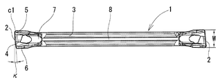
- FIG. 1 is an enlarged front cross-sectional view of the main part of the parting tool in FIG.
- the perspective view which shows the detail of the upper surface at the front end side of the tool for parting-off processing of FIG.
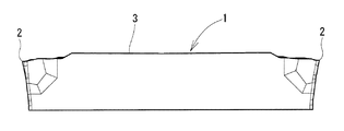
- FIG. 1 is an enlarged plan view of the tip of the parting tool shown in FIG. Sectional view along the line DD in FIG. Sectional view along line EE in FIG. Sectional view along line FF in FIG.
- the illustrated parting-off processing tool 1 is configured as a cutting edge exchangeable cutting insert that is detachably mounted on a holder (not shown).
- Cutting edges 2 are provided at both axial ends of the tool 1. Since the shapes of the cutting edges 2 at both ends of the tool 1 in the axial direction and the upper surface 3 of the portion involved in cutting are substantially the same, the following description will be given only for the configuration on one end side.
- the upper surface 3 is provided with rake surfaces 4 and first to third breaker protrusions 5 to 7 each having a breaker surface with an inclination angle of 30 °.
- the parting tool 1 shown in the drawing is a V-shaped fitting with a holder as disclosed in Patent Document 1, that is, a V groove 8 (see FIGS. 1, 3, 4, and 7) on the upper surface 3 of the tool. And a lower jaw that fits in a V-shape with a V groove 9 (see FIG. 3) on the lower surface of the tool, and inserts a cutting tool 1 between the upper jaw and the lower jaw to apply pressure from the upper jaw with a bolt or the like. Used by attaching to a holder of the type that is held over.
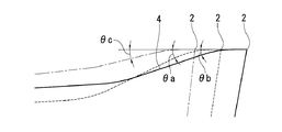
- the cutting edge 2 of the parting tool 1 is provided with the front cutting edge angle ⁇ shown in FIGS. 1 and 7, and the first corner c1 at one end of the cutting edge 2 is positioned at the forefront of the tool.
- the second corner c2 at the other end is in a position in the rear direction of the tool axis from the first corner c1.
- a rake face 4 is provided on the upper surface 3 along the cutting edge, and a first breaker protrusion 5 and a second breaker protrusion 6 are formed on the upper surface 3 along the side surfaces on the first corner c1 side and the second corner c2 side.
- a third breaker projection 7 is provided, which is a combination of a small projection and a slope in the rearward direction of the tool axis of the rake face 4.
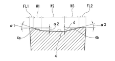
- a portion of the scooping face 4 between the first breaker protrusion 5 and the second breaker protrusion 6 falls downward from the position of the cutting edge 2.
- the maximum portion of the sagging amount d is biased toward the second corner c2.
- the rake angle of the region of the rake face 4 that falls from the position of the cutting edge 2 is related to the rake angle ⁇ b on the first corner side and the rake angle ⁇ c on the second corner side (see FIGS. 6 and 10), ⁇ b> ⁇ c. Is set to a value that holds.
- the rake angle ⁇ b on the first corner c1 side, the rake angle ⁇ a on the center of the cutting edge, and the rake angle ⁇ c on the second corner c2 side are in a relationship of ⁇ a> ⁇ b> ⁇ c. These rake angles are preferably in the following ranges. 20 ° ⁇ ⁇ a ⁇ 40 ° 12 ° ⁇ ⁇ b ⁇ 24 ° 6 ° ⁇ ⁇ c ⁇ 18 °
- the values of the rake angle ⁇ b on the first corner c1 side and the rake angle ⁇ c on the second corner c2 side can vary in the blade width direction, but the rake angle ⁇ b can be changed from the cutting edge on the first corner c1 side,
- the rake angle ⁇ c is preferably specified by a value at a position of 25% of the blade width W from the end of the cutting edge 2 on the second corner c2 side.
- the cutting edge angle ⁇ shown in FIGS. 1 and 7 is set to 5 °
- the rake angle ⁇ a shown in FIG. 6 is set to 30 °
- ⁇ b is set to 18 °
- ⁇ c is set to 12 °.
- the appropriate values of ⁇ b and ⁇ c vary depending on the size of the front cutting edge angle ⁇ , the presence or absence of the first and second breaker protrusions 5 and 6, the size, and the like.
- the front cutting edge angle ⁇ is preferably about 5 ° to 15 ° in view of the effect of reducing the amount of the remaining part of the workpiece.
- the rake angle of the rake face 4 in both sides is set to 0 °, this angle is not limited to 0 °.
- the first breaker protrusion 5 and the second breaker protrusion 6 have the widths FL1 and FL2 shown in FIG. 8 (the width of the tip portion connected to the rake face (land) having a rake angle of 0 °) set to FL1 ⁇ FL2. Yes.
- the outflow resistance of the chip is larger on the second corner c2 side than on the first corner c1 side. This also causes a speed difference on both sides of the flowing out chips (the outflow speed becomes slower on the second corner c2 side), and this speed difference is added to the outflow speed difference caused by the rake angle difference to correct the chip outflow direction. The effect is further enhanced.
- the width W2 of the rake face between 4a and 4b, the slope angle ⁇ 1 of the slope 4a, the slope angle ⁇ 3 of the slope 4b, and the slope angle ⁇ 2 of the rake face 4 between the slopes 4a and 4b are preferably in the following ranges.
- the inclination angles ⁇ 1, ⁇ 2, and ⁇ 3 are angles based on a line parallel to the cutting edge 2.
- the third breaker protrusion 7 is disposed in the tool axis rear direction of the rake face 4.
- the distance L (see FIG. 9) from the cutting edge 2 to the upper end of the inclined surface having the inclination angle of 30 ° of the third breaker projection 7 is set to 1.8 mm in the illustrated tool, but this is only an example.
- the right-handed tool with the first corner c1 in the cutting direction on the right side is taken as an example, but the left-handed tool, which is not described, has the same basic configuration as the right-handed tool. is there.
- Blade width W 2 mm
- front cutting edge angle ⁇ 5 °
- rake angle ⁇ a 30 °
- ⁇ b 18 °
- ⁇ c 12 °
- tip width FL1 0.12 mm of first breaker protrusion
- Cutting conditions: Cutting speed Vc 100 m / min
- feed f 0.10 mm / rev Work material: SCM415
- the tool of the present invention uses a structure in which only the rake angle of the rake face is different on the left and right sides (the first corner side and the second corner side) and a structure in which only the widths of the first breaker protrusion and the second breaker protrusion are different. If a thing is made, a big difference can be produced with the outflow speed of the right and left of a chip.
Landscapes
- Engineering & Computer Science (AREA)
- Mechanical Engineering (AREA)
- Cutting Tools, Boring Holders, And Turrets (AREA)
Abstract
前切れ刃角の付された切れ刃を備える突っ切り加工用工具を対象にして、加工面の切屑による傷つきの懸念を減少させるために、切屑の流出が工具軸方向にコントロールされるようにすることを目的とする。切れ刃2に前切れ刃角の付された突っ切り加工用工具の上面3の形状を幅方向中心基準で左右非対称となし、工具の最先端に位置する第1コーナ側のすくい面のすくい角をθb、第2コーナ側のすくい面のすくい角をθcとしたとき、θb>θcが成立するようにした。
Description
本発明は、突っ切り加工に利用する工具、より詳しくは、前切れ刃角の付された切れ刃を備えていながら切屑の流出が工具軸方向にコントロールされるようにした突っ切り加工用工具に関する。
突っ切り加工用工具として、例えば、下記特許文献1に開示されたものがある。
その特許文献1に記載された突っ切り加工用工具は、切れ刃に前切れ刃角の付与された勝手付の切削インサートであって、前切れ刃角の影響によって切削インサートに加わる切削反力の偏りを、切れ刃を傾けることによって補正するようにしている。
その特許文献1に記載された突っ切り加工用工具は、切れ刃に前切れ刃角の付与された勝手付の切削インサートであって、前切れ刃角の影響によって切削インサートに加わる切削反力の偏りを、切れ刃を傾けることによって補正するようにしている。
なお、前切れ刃角の付与された突っ切り加工用工具は、前切れ刃角0°の工具を用いてなされる突っ切り加工で問題となるワークのいわゆるへそ残り対策として有効な工具であることが知られている。
前切れ刃角0°の工具を用いてなされる突っ切り加工では、ワークの一部がまだ切り残されている状態のときにワークがちぎれるように分断されて切り落とされる側の加工面の中心にへそ(未加工の凸部)が残り易い。これに対し、前切れ刃角の付与された突っ切り加工用工具は、最先端のコーナによる切削を後退した側のコーナによる切削に先行させることでワークが分断される前にへそとして残る箇所を切断することができ、へそ残りを小さくすることができる。
前切れ刃角の付与された突っ切り加工用工具は、上述したようにワークのへそ残り対策として有効なものであるが、切れ刃が工具軸方向と垂直な線に対して傾斜しているため、切屑がワークの加工済みの面に向けて流出する難点がある。
突っ切り加工や溝入れ加工で加工時に生成される切屑は、通常、切れ刃に対して垂直な方向に流出する。そのため、前切れ刃角の付与された突っ切り用工具による加工では、切屑が切れ刃の最先端側コーナによって加工され、そのコーナ側の面に向かって流出し、加工済みの面(ワークの一部が切り落とされる前の溝面)を傷付ける問題が発生しやすい。
本発明は、前切れ刃角の付された切れ刃を備える突っ切り加工用工具を対象にして、加工面の切屑による傷つきの懸念を減少させるために、切屑の流出が工具軸方向にコントロールされるようにすることを課題としている。なお、以降の記載では、工具軸方向のうち、工具軸方向に沿って切れ刃を被削材に近づかせる方向(突っ切り方向)を工具軸前方向、工具軸方向に沿って切れ刃を被削材から遠ざかる方向(反突っ切り方向)を工具軸後方向とする。
上記の課題を解決するため、本発明においては、切れ刃に前切れ刃角の付された突っ切り加工用工具を以下の通りに構成した。即ち、上面の形状が幅方向中心基準で左右非対称をなし、工具の最先端に位置する第1コーナ側のすくい面のすくい角をθb、第1コーナよりも工具軸後方向の位置にある第2コーナ側のすくい面のすくい角をθcとしたとき、θb>θcが成立するものにした。なお、ここで言うすくい角は、工具軸と平行な線に沿った断面におけるすくい角0°のすくい面からの角度である(以下も同様)。
かかる突っ切り加工用工具は、第1コーナ側にある第1ブレーカ突起の幅をFL1、第2コーナ側にある第2ブレーカ突起の幅をFL2としたとき、FL1<FL2が併せて成立するものにするとよりよい効果を期待できて好ましい。
また、前記第1コーナ側のすくい角θbと第2コーナ側のすくい角θcについて2°以上の角度差をつけると角度差による矯正効果が明確に現われて好ましい。
このほか、上面の形状を、工具の幅方向中央部におけるすくい面のすくい角θaを、前記第1コーナ側のすくい角θb及び第2コーナ側のすくい角θcよりも大きく設定することが好ましい。さらに、すくい面の工具軸後方向にブレーカ突起を配置した形状にするのも好ましい。
本発明の突っ切り加工用工具は、上面形状を幅方向中心基準で左右非対称にすることで第1コーナ側と第2コーナ側における切屑の流出速度に差を生じさせ、その流出速度の差を利用して切屑の流出方向を矯正する。
切屑の流出速度は、すくい角が大きい側、或いは、先端両側のブレーカ突起の幅が狭い側で速くなる。すくい角が大きい側や先端両側のブレーカ突起の幅が狭い側は、すくい角が小さい側やブレーカ突起の幅が広い側に比べて切屑の擦過抵抗が小さく抑えられるからである。
これにより、切れ刃の第1コーナ側に向おうとする切屑の流れが矯正され、切屑が工具の軸方向を指向するようになる。そのために、加工済みの面に向って切屑が流出することが抑制される。
また、工具軸方向に向って流れる切屑は、すくい面の後方にブレーカ突起を配置することでそのブレーカ突起を利用して良好にカールさせて分断することができる。その分断処理によって切屑が長く延び出すことが抑制され、切屑の排出が安定する。そのために、生成された切屑が加工済みの面に突き当たることが減少し、加工済みの面が切屑によって傷つけられる不具合が減少する。
以下、図1~図10に基づいて、本発明の突っ切り加工用工具の実施の形態を説明する。例示の突っ切り加工用工具1は、ホルダ(図示せず)に着脱自在に装着して使用する刃先交換式切削インサートとして構成されたものである。その工具1の軸方向両端には、切れ刃2が設けられている。その工具1の軸方向両端の切れ刃2と、切削に関与する部分の上面3の形状はほぼ同一であるので、以下の説明は一端側の構成についてのみ行う。
上面3には、すくい面4と各々が傾斜角30°のブレーカ面を有する第1~第3のブレーカ突起5~7が設けられている。
図示の突っ切り加工用工具1は、特許文献1が開示しているようなホルダ、即ち、工具の上面3のV溝8(図1、図3、図4、図7参照)とV字嵌合する上顎と、工具の下面のV溝9(図3参照)とV字嵌合する下顎を有し、その上顎と下顎間に突っ切り加工用工具1を挿入してボルト等により上顎部から圧力をかけて保持するタイプのホルダに装着して使用される。
この突っ切り加工用工具1の切れ刃2には図1、図7に示した前切れ刃角κが付されており、その切れ刃2の一端の第1コーナc1が工具の最先端に位置し、他端の第2コーナc2は、第1コーナc1から工具軸後方向の位置にある。
切れ刃2は、各部の高さ位置が同じになっている。その切れ刃に沿って上面3にすくい面4が設けられ、さらに、第1コーナc1側と第2コーナc2側の各側面に沿って上面3に第1ブレーカ突起5と第2ブレーカ突起6がそれぞれ設けられ、なおかつ、すくい面4の工具軸後方向に小突起と斜面を組み合わせた第3ブレーカ突起7が設けられている。
すくい面4は、第1ブレーカ突起5と第2ブレーカ突起6間にある部分が切れ刃2の位置から下方に落ち込んでいる。例示の工具については、図8に示すように、その落ち込み量dの最大部が第2コーナc2側に偏っている。
また、すくい面4の切れ刃2の位置から落ち込んだ領域のすくい角は、第1コーナ側のすくい角θb、第2コーナ側のすくい角θc(図6、図10参照)に関し、θb>θcが成立する値に設定されている。
第1コーナc1側のすくい角θb、切れ刃中央部のすくい角θa、第2コーナc2側のすくい角θcは、θa>θb>θcの関係にある。これらのすくい角は、以下の範囲が好ましい。
20°≦θa≦40°
12°≦θb≦24°
6°≦θc≦18°
20°≦θa≦40°
12°≦θb≦24°
6°≦θc≦18°
第1コーナc1側のすくい角θbと第2コーナc2側のすくい角θcの値は、刃幅方向に変動し得るが、すくい角θbは、第1コーナc1側の切れ刃端部から、また、すくい角θcは、第2コーナc2側の切れ刃2の端部からそれぞれ刃幅Wの25%の位置における値で規定するのが望ましい。
すくい角θbとθcを切れ刃の端部、すなわちコーナ部の近くで規定すると、切りくず流出方向を強く矯正したい場合にθbとθcの差異が大となるようθbを大きくすることにより、元々欠損が生じやすいコーナ近傍のすくい角を大きく設定することとなる。このため、刃先欠損の懸念が増大する。また規定箇所が刃幅の中央に寄り過ぎると、θbとθcの差異を大きくしても切屑の流れに対するすくい角の影響が小さくなるので、切り屑流出方向を矯正する効果が出にくい。このため、切れ刃2の端部から刃幅W(図1参照)の25%の位置で規定するのが望ましい。
なお、例示の工具は、図1、図7に示した前切れ刃角κを5°、図6に示したすくい角θaを30°、θbを18°、θcを12°に設定したが、θb、θcの値は、前切れ刃角κの大きさや、第1、第2ブレーカ突起5、6の有無、大きさなどによってその適正値が変動する。前切れ刃角κは、ワークのへそ残り量の低減効果を考えると5°~15°程度が好ましい。また、両側部(第1、第2ブレーカ突起5、6と切れ刃2との間)におけるすくい面4のすくい角は共に0°に設定したが、この角度も0°に限定されない。
第1ブレーカ突起5と第2ブレーカ突起6は、図8に示した幅(すくい角0°のすくい面(ランド)と連なった先端部の幅)FL1とFL2を、FL1<FL2に設定している。
このブレーカ幅の違いにより、第2コーナc2側では第1コーナc1側に比べて切屑の流出抵抗が大きくなる。これによっても流出する切屑の両側部に速度差が生じ(第2コーナc2側で流出速度が遅くなる)、その速度差がすくい角の違いによって生じる流出速度差と合算されて切屑流出方向の矯正効果がより高められる。
なお、図8における第1ブレーカ突起5の幅FL1、第2ブレーカ突起6の幅FL2、第1ブレーカ突起5側の斜面4aの幅W1、第2ブレーカ突起6側の斜面4bの幅W3、斜面4aと4b間のすくい面の幅W2、斜面4aの傾斜角α1、斜面4bの傾斜角α3、斜面4aと4b間のすくい面4の傾斜角α2は、以下の範囲が好ましい。なお、Wは刃幅であって、W=FL1+FL2+W1+W2+W3の関係式が成り立つ。傾斜角α1、α2、α3は切れ刃2と平行な線を基準にした角度である。
0≦FL1≦0.1W
0≦FL2≦0.2W
0.1W≦W1≦0.2W
0≦W2≦0.5W
0.15W≦W3≦0.35W
12°≦α1≦24°
0°≦α2≦6°
10°≦α3≦20°
0≦FL2≦0.2W
0.1W≦W1≦0.2W
0≦W2≦0.5W
0.15W≦W3≦0.35W
12°≦α1≦24°
0°≦α2≦6°
10°≦α3≦20°
第3ブレーカ突起7は、すくい面4の工具軸後方向に配置されている。切れ刃2からその第3ブレーカ突起7の傾斜角30°の斜面の上端までの距離L(図9参照)は、例示の工具では1.8mmに設定したが、これは一例に過ぎない。
なお、以上の説明は、第1コーナc1が切込み方向に見て右にある右勝手の工具を例に挙げて行ったが、説明を省略した左勝手の工具も基本構成は右勝手と同じである。
刃幅W=2mm、前切れ刃角κ=5°、すくい角θa=30°、θb=18°、θc=12°、第1ブレーカ突起の先端幅FL1=0.12mm、第2ブレーカ突起の先端幅FL2=0.24mm、切れ刃から第3ブレーカ突起の斜面の上端までの距離L=1.8mmの仕様の突っ切り加工用工具を試作して以下の条件で被削材の突っ切り加工を行った。
切削条件:切削速度Vc=100m/min、送りf=0.10mm/rev
被削材 :SCM415
切削条件:切削速度Vc=100m/min、送りf=0.10mm/rev
被削材 :SCM415
この試験の結果、送りf=0.10mm/revでは切屑が工具軸方向に流れてブレーカ突起により良好にカール分断された。
また、送りfを0.20mm/revに代えての突っ切り加工でも切屑の流出方向が工具軸方向に矯正され、本願発明の構成が有効であることが確認された。
本発明の工具は、すくい面のすくい角のみを左右(第1コーナ側と第2コーナ側)で異ならせる構造と、第1ブレーカ突起と第2ブレーカ突起の幅のみを異ならせる構造を併用したものにすると、切屑の左右の流出速度により大きな差を生じさせることができる。
なお、以上の説明は、交換可能な切削インサートを例に挙げて説明したが、本発明は、切れ刃を有するチップを本体に固着した工具や切れ刃を本体に一体に形成する工具にも適用できる。また、その用途は、加工される溝の溝底が傾斜していることが許容される場合には、溝入れ加工にも利用でき、突っ切り加工に限定されない。本発明の範囲は、請求の範囲の記載によって示され、さらに請求の範囲の記載と均等の意味および範囲内でのすべての変更を含むものである。
1 突っ切り加工用工具
2 切れ刃
3 上面
4 すくい面
4a、4b 斜面
5 第1ブレーカ突起
6 第2ブレーカ突起
7 第3ブレーカ突起
8,9 V溝
c1 第1コーナ
c2 第2コーナ
κ 前切れ刃角
θa 切れ刃中央部のすくい角
θb 第1コーナ側のすくい角
θc 第2コーナ側のすくい角
FL1 第1ブレーカ突起の幅
FL2 第2ブレーカ突起の幅
W1 第1ブレーカ突起側の斜面4aの幅
W2 斜面4aと4b間のすくい面の幅
W3 第2ブレーカ突起側の斜面4bの幅
L 切れ刃から第3ブレーカ突起の斜面の上端までの距離
α1 斜面4aの傾斜角
α2 すくい面4の傾斜角
α3 斜面4bの傾斜角
d すくい面の切れ刃位置からの落ち込み量
Claims (3)
- 切れ刃に前切れ刃角の付された突っ切り加工用工具であって、上面の形状が幅方向中心基準で左右非対称をなし、工具の最先端に位置する第1コーナ側のすくい面のすくい角をθb、第1コーナよりも工具軸後方向の位置にある第2コーナ側のすくい面のすくい角をθcとしたとき、θb>θcが成立する突っ切り加工用工具。
- 前記工具の最先端に位置する第1コーナ側の側面に沿って上面に設ける第1ブレーカ突起の幅をFL1、第1コーナよりも工具軸後方向の位置にある第2コーナ側の側面に沿って上面に設ける第2ブレーカ突起の幅をFL2としたとき、FL1<FL2が成立する請求項1に記載の突っ切り加工用工具。
- 前記すくい面の工具軸後方向にブレーカ突起を配置した請求項1又は2に記載の突っ切り加工用工具。
Priority Applications (3)
| Application Number | Priority Date | Filing Date | Title |
|---|---|---|---|
| CN201380011088.0A CN104136155B (zh) | 2012-10-26 | 2013-09-18 | 切断加工工具 |
| EP13849852.2A EP2913129B1 (en) | 2012-10-26 | 2013-09-18 | Cutting-off processing tool |
| US14/378,164 US9630255B2 (en) | 2012-10-26 | 2013-09-18 | Cutting-off processing tool |
Applications Claiming Priority (2)
| Application Number | Priority Date | Filing Date | Title |
|---|---|---|---|
| JP2012236470A JP6038594B2 (ja) | 2012-10-26 | 2012-10-26 | 突っ切り加工用工具 |
| JP2012-236470 | 2012-10-26 |
Publications (1)
| Publication Number | Publication Date |
|---|---|
| WO2014065046A1 true WO2014065046A1 (ja) | 2014-05-01 |
Family
ID=50544426
Family Applications (1)
| Application Number | Title | Priority Date | Filing Date |
|---|---|---|---|
| PCT/JP2013/075088 WO2014065046A1 (ja) | 2012-10-26 | 2013-09-18 | 突っ切り加工用工具 |
Country Status (5)
| Country | Link |
|---|---|
| US (1) | US9630255B2 (ja) |
| EP (1) | EP2913129B1 (ja) |
| JP (1) | JP6038594B2 (ja) |
| CN (1) | CN104136155B (ja) |
| WO (1) | WO2014065046A1 (ja) |
Cited By (2)
| Publication number | Priority date | Publication date | Assignee | Title |
|---|---|---|---|---|
| WO2018079491A1 (ja) * | 2016-10-31 | 2018-05-03 | 京セラ株式会社 | 切削インサート、切削工具及び切削加工物の製造方法 |
| WO2018084110A1 (ja) * | 2016-11-07 | 2018-05-11 | 住友電工ハードメタル株式会社 | 突っ切り加工用工具 |
Families Citing this family (15)
| Publication number | Priority date | Publication date | Assignee | Title |
|---|---|---|---|---|
| EP2623236B1 (en) | 2010-09-29 | 2020-04-22 | Kyocera Corporation | Cutting insert, cutting tool with said cutting insert, and method for producing cut product using said cutting tool |
| JP6206801B2 (ja) * | 2013-09-09 | 2017-10-04 | 住友電工ハードメタル株式会社 | 切削インサート |
| JP6272345B2 (ja) * | 2013-10-29 | 2018-01-31 | 京セラ株式会社 | 切削インサート及び切削工具、並びにそれらを用いた切削加工物の製造方法 |
| WO2015146956A1 (ja) * | 2014-03-25 | 2015-10-01 | 京セラ株式会社 | 切削インサート、切削工具及び切削加工物の製造方法 |
| JP1560554S (ja) * | 2015-11-17 | 2016-10-11 | ||
| US10363722B2 (en) * | 2017-03-23 | 2019-07-30 | Iscar, Ltd. | Blade-shaped cutting insert and cutting tool therefor |
| EP3450063A1 (en) * | 2017-08-30 | 2019-03-06 | Tungaloy Corporation | Cutting tool |
| US11137008B2 (en) | 2018-01-12 | 2021-10-05 | Illinois Tool Works Inc. | Self-drilling anchor assembly |
| DE102018130788A1 (de) * | 2018-12-04 | 2020-06-04 | Hartmetall-Werkzeugfabrik Paul Horn Gmbh | Schneidplatte und Werkzeug zur spanenden Bearbeitung eines Werkstücks |
| CN109482919B (zh) * | 2019-01-08 | 2020-08-11 | 广东工业大学 | 一种带有断屑结构的可转位切削刀片 |
| USD886171S1 (en) * | 2019-01-09 | 2020-06-02 | Illinois Tool Works Inc. | Anchor assembly drill bit |
| USD886172S1 (en) * | 2019-01-09 | 2020-06-02 | Illinois Tool Works Inc. | Anchor assembly drill bit |
| USD886168S1 (en) * | 2019-01-09 | 2020-06-02 | Illinois Tool Works Inc. | Anchor assembly drill bit |
| USD886169S1 (en) * | 2019-01-09 | 2020-06-02 | Illinois Tool Works Inc. | Anchor assembly drill bit |
| USD886170S1 (en) * | 2019-01-09 | 2020-06-02 | Illinois Tool Works Inc. | Anchor assembly drill bit |
Citations (5)
| Publication number | Priority date | Publication date | Assignee | Title |
|---|---|---|---|---|
| JPH01121109A (ja) * | 1986-05-07 | 1989-05-12 | Seco Tools Ab | 切削インサ−ト |
| JPH07602U (ja) * | 1993-06-02 | 1995-01-06 | 三菱マテリアル株式会社 | 突切り用スローアウェイチップ |
| JP2005103655A (ja) * | 2003-09-26 | 2005-04-21 | Kyocera Corp | 溝入れ加工用スローアウェイチップ |
| JP2006231458A (ja) * | 2005-02-24 | 2006-09-07 | Kyocera Corp | 突切り工具用スローアウェイチップ |
| WO2008117822A1 (ja) * | 2007-03-27 | 2008-10-02 | Kyocera Corporation | 切削インサートおよび切削工具、並びにそれを用いた被削材の切削方法 |
Family Cites Families (27)
| Publication number | Priority date | Publication date | Assignee | Title |
|---|---|---|---|---|
| US2392001A (en) * | 1944-08-07 | 1946-01-01 | John R Raper | Cutting tool |
| US2677170A (en) * | 1951-06-16 | 1954-05-04 | Robert J Kuns | Cutting bit |
| US4880338A (en) * | 1988-12-07 | 1989-11-14 | Gte Valenite Corporation | Cutting insert |
| GB8903075D0 (en) * | 1989-02-10 | 1989-03-30 | Iscar Hartmetall | A cutting insert |
| DE3907922A1 (de) * | 1989-03-11 | 1990-04-26 | Zinner Gmbh Praezisionswerkzeu | Spanendes werkzeug |
| DE8913805U1 (ja) * | 1989-11-23 | 1991-03-21 | Hertel Ag Werkzeuge + Hartstoffe, 8510 Fuerth, De | |
| DE4318479A1 (de) | 1993-06-03 | 1994-12-08 | Krupp Widia Gmbh | Stechdrehwerkzeug |
| DE4437093A1 (de) * | 1994-10-17 | 1996-04-18 | Widia Gmbh | Vieleckiger Schneideinsatz |
| US5807031A (en) * | 1995-03-10 | 1998-09-15 | Mitsubishi Materials Corp. | Throw-away tip and throw-away type cutter |
| JP3250939B2 (ja) * | 1995-04-26 | 2002-01-28 | 京セラ株式会社 | 切削インサート |
| IL120422A0 (en) | 1997-03-11 | 1997-07-13 | Iscar Ltd | A cutting insert |
| JP2000271806A (ja) * | 1999-03-23 | 2000-10-03 | Ngk Spark Plug Co Ltd | 円弧状切れ刃付きチップ |
| US6742971B2 (en) * | 2002-02-19 | 2004-06-01 | Manchester Tool Company | Cutting insert |
| CN101979195B (zh) | 2002-10-18 | 2013-06-19 | 肯纳合金公司 | 刀夹和带有断屑面的金属切削刀片 |
| IL154649A (en) * | 2003-02-27 | 2007-10-31 | Uzi Gati | Cutting placement for diligent operations |
| DE10344961A1 (de) | 2003-09-27 | 2005-04-28 | Kennametal Inc | Schneidkörper, insbesondere zum Stech- und Längsdrehen |
| WO2008053633A1 (fr) | 2006-10-31 | 2008-05-08 | Kyocera Corporation | Garniture de coupe |
| JP5310547B2 (ja) * | 2007-04-20 | 2013-10-09 | 三菱マテリアル株式会社 | 切削インサートによる切削方法及び切削インサート |
| PL2160261T3 (pl) * | 2007-06-26 | 2012-10-31 | Taegu Tec Ltd | Wkładka skrawająca z występami utworzonymi w jej obszarze narożnym |
| JP5104076B2 (ja) | 2007-07-04 | 2012-12-19 | 三菱マテリアル株式会社 | 切削インサート |
| KR100901470B1 (ko) | 2007-07-05 | 2009-06-08 | 대구텍 주식회사 | 코너 리세스부를 지니는 절삭 인서트 |
| JP5158490B2 (ja) * | 2008-03-06 | 2013-03-06 | 住友電工ハードメタル株式会社 | 刃先交換式切削チップ |
| CN102596459B (zh) * | 2009-10-29 | 2015-07-15 | 京瓷株式会社 | 切削镶刀及切削工具、以及使用该切削工具的切削加工物的制造方法 |
| US8770895B2 (en) * | 2010-01-29 | 2014-07-08 | Kyocera Corporation | Cutting insert, cutting tool, and method of cutting workpiece using them |
| US9925595B2 (en) * | 2012-09-27 | 2018-03-27 | Kyocera Corporation | Cutting insert and cutting tool |
| DE102014102800A1 (de) * | 2013-03-04 | 2014-09-04 | Kennametal India Limited | Schneideinsatz mit assymetrischem Spanformer |
| JP6272345B2 (ja) * | 2013-10-29 | 2018-01-31 | 京セラ株式会社 | 切削インサート及び切削工具、並びにそれらを用いた切削加工物の製造方法 |
-
2012
- 2012-10-26 JP JP2012236470A patent/JP6038594B2/ja active Active
-
2013
- 2013-09-18 EP EP13849852.2A patent/EP2913129B1/en active Active
- 2013-09-18 CN CN201380011088.0A patent/CN104136155B/zh active Active
- 2013-09-18 US US14/378,164 patent/US9630255B2/en active Active
- 2013-09-18 WO PCT/JP2013/075088 patent/WO2014065046A1/ja active Application Filing
Patent Citations (6)
| Publication number | Priority date | Publication date | Assignee | Title |
|---|---|---|---|---|
| JPH01121109A (ja) * | 1986-05-07 | 1989-05-12 | Seco Tools Ab | 切削インサ−ト |
| JP2768939B2 (ja) | 1986-05-07 | 1998-06-25 | セコ ツ−ルズ アクテイエボラ−グ | 切削インサート |
| JPH07602U (ja) * | 1993-06-02 | 1995-01-06 | 三菱マテリアル株式会社 | 突切り用スローアウェイチップ |
| JP2005103655A (ja) * | 2003-09-26 | 2005-04-21 | Kyocera Corp | 溝入れ加工用スローアウェイチップ |
| JP2006231458A (ja) * | 2005-02-24 | 2006-09-07 | Kyocera Corp | 突切り工具用スローアウェイチップ |
| WO2008117822A1 (ja) * | 2007-03-27 | 2008-10-02 | Kyocera Corporation | 切削インサートおよび切削工具、並びにそれを用いた被削材の切削方法 |
Cited By (7)
| Publication number | Priority date | Publication date | Assignee | Title |
|---|---|---|---|---|
| WO2018079491A1 (ja) * | 2016-10-31 | 2018-05-03 | 京セラ株式会社 | 切削インサート、切削工具及び切削加工物の製造方法 |
| JPWO2018079491A1 (ja) * | 2016-10-31 | 2019-07-25 | 京セラ株式会社 | 切削インサート、切削工具及び切削加工物の製造方法 |
| WO2018084110A1 (ja) * | 2016-11-07 | 2018-05-11 | 住友電工ハードメタル株式会社 | 突っ切り加工用工具 |
| CN109789490A (zh) * | 2016-11-07 | 2019-05-21 | 住友电工硬质合金株式会社 | 切削工具 |
| KR20190083641A (ko) | 2016-11-07 | 2019-07-12 | 스미또모 덴꼬오 하드메탈 가부시끼가이샤 | 컷오프 가공용 공구 |
| JPWO2018084110A1 (ja) * | 2016-11-07 | 2019-09-19 | 住友電工ハードメタル株式会社 | 突っ切り加工用工具 |
| US10926337B2 (en) | 2016-11-07 | 2021-02-23 | Sumitomo Electric Hardmetal Corp. | Cutting-off processing tool |
Also Published As
| Publication number | Publication date |
|---|---|
| EP2913129A1 (en) | 2015-09-02 |
| JP6038594B2 (ja) | 2016-12-07 |
| CN104136155A (zh) | 2014-11-05 |
| EP2913129A4 (en) | 2016-05-25 |
| EP2913129B1 (en) | 2019-02-27 |
| US20150056029A1 (en) | 2015-02-26 |
| CN104136155B (zh) | 2016-05-25 |
| US9630255B2 (en) | 2017-04-25 |
| JP2014083663A (ja) | 2014-05-12 |
Similar Documents
| Publication | Publication Date | Title |
|---|---|---|
| WO2014065046A1 (ja) | 突っ切り加工用工具 | |
| US8672590B2 (en) | Cutting insert | |
| JP5024483B2 (ja) | 切削インサート | |
| EP2558235B1 (en) | Cutting tool | |
| US10384268B1 (en) | Grooving insert having rearwardly pointing arrowhead-shaped chip former | |
| JP5592954B2 (ja) | 切削インサートおよび切削工具、並びにそれを用いた切削加工物の製造方法 | |
| JP6361948B2 (ja) | 切削インサートおよび切削工具 | |
| JP4849815B2 (ja) | 切削インサートおよび溝入れ加工用切削工具 | |
| TWI773866B (zh) | 具有含間隔開的向上凸起刃帶部之刃帶的切削嵌件、及設有該切削嵌件的非旋轉式切削刀具 | |
| JP5056215B2 (ja) | 切削インサート | |
| JP5104076B2 (ja) | 切削インサート | |
| JP5380746B2 (ja) | 切削工具 | |
| JP4969089B2 (ja) | 溝入れ加工用切削インサート、溝入れ加工用切削工具および切削方法 | |
| JP2011167805A (ja) | 溝入れ・突っ切り加工用切削インサート | |
| CN110636915B (zh) | 包括具有前缘和后缘部件切削刃的分裂切削刃的切削刀片 | |
| CN111448021B (zh) | 用于窄宽度的切断操作的高速进给的切断刀片 | |
| JP5243396B2 (ja) | 隅削り用刃先交換式チップとミーリングカッタ | |
| JP4854360B2 (ja) | 切削インサートおよびそれを装着してなる切削工具 | |
| JP4961841B2 (ja) | 中ぐり工具 | |
| JP5045274B2 (ja) | 切削インサート | |
| JP4892865B2 (ja) | 中ぐり工具 | |
| JPH11300508A (ja) | スローアウェイチップ |
Legal Events
| Date | Code | Title | Description |
|---|---|---|---|
| 121 | Ep: the epo has been informed by wipo that ep was designated in this application |
Ref document number: 13849852 Country of ref document: EP Kind code of ref document: A1 |
|
| WWE | Wipo information: entry into national phase |
Ref document number: 14378164 Country of ref document: US |
|
| WWE | Wipo information: entry into national phase |
Ref document number: 2013849852 Country of ref document: EP |
|
| NENP | Non-entry into the national phase |
Ref country code: DE |