WO2014064829A1 - 帳票出力端末変更装置、帳票出力端末変更システム、帳票出力端末変更方法及び帳票出力端末変更プログラム - Google Patents
帳票出力端末変更装置、帳票出力端末変更システム、帳票出力端末変更方法及び帳票出力端末変更プログラム Download PDFInfo
- Publication number
- WO2014064829A1 WO2014064829A1 PCT/JP2012/077702 JP2012077702W WO2014064829A1 WO 2014064829 A1 WO2014064829 A1 WO 2014064829A1 JP 2012077702 W JP2012077702 W JP 2012077702W WO 2014064829 A1 WO2014064829 A1 WO 2014064829A1
- Authority
- WO
- WIPO (PCT)
- Prior art keywords
- output terminal
- information
- output
- terminal
- user terminal
- Prior art date
- Legal status (The legal status is an assumption and is not a legal conclusion. Google has not performed a legal analysis and makes no representation as to the accuracy of the status listed.)
- Ceased
Links
Images



Classifications
-
- G—PHYSICS
- G06—COMPUTING OR CALCULATING; COUNTING
- G06Q—INFORMATION AND COMMUNICATION TECHNOLOGY [ICT] SPECIALLY ADAPTED FOR ADMINISTRATIVE, COMMERCIAL, FINANCIAL, MANAGERIAL OR SUPERVISORY PURPOSES; SYSTEMS OR METHODS SPECIALLY ADAPTED FOR ADMINISTRATIVE, COMMERCIAL, FINANCIAL, MANAGERIAL OR SUPERVISORY PURPOSES, NOT OTHERWISE PROVIDED FOR
- G06Q10/00—Administration; Management
- G06Q10/10—Office automation; Time management
Definitions
- the present invention provides an output terminal that outputs a plurality of reports from one or more user terminals in a system that centrally manages one or more user terminals and a plurality of output terminals connected via a network.
- the present invention relates to a form output terminal changing device, a form output terminal changing system, a form output terminal changing method, and a form output terminal changing program.
- one or two or more user terminals and a plurality of output terminals are connected to one or two or more servers via a network, and the plurality of terminals are centrally managed by this server.
- output destinations of forms output by one or more user terminals may be centrally managed by the server.
- Each user accesses the server through one or more user terminals, and when the server issues a form output request to the server, the server determines the output destination of the form, makes a form output request to the output terminal, and outputs it.
- the terminal outputs a form according to the form output request.
- the user terminal has the authority to change the output terminal to output the form even if the user can easily find it unsuitable as an output terminal due to failure or out of paper. In other words, the user could not change without requesting the administrator who manages the server to change the output destination of the form.
- the present invention enables the user terminal to change the output destination of the form, and information to the user terminal so that the user can easily grasp the position of the output terminal after the change. It is an object to provide a form output terminal changing device, a form output terminal changing system, a form output terminal changing method, and a form output terminal changing program.
- the form output terminal changing device stores output terminal information related to a plurality of output terminals set for each one or a group of forms as an output destination of a plurality of forms output by a user terminal.
- a storage unit output terminal installation area information relating to an area where a plurality of output terminals are installed, and output terminal position information that associates the position where each of the plurality of output terminals is installed with a position in the output terminal arrangement area information are stored.
- An output terminal arrangement information storage unit and an output terminal information change unit that changes one or more output terminal information in response to a change request for one or more output terminal information among a plurality of output terminal information from a user terminal And, in response to a transmission request for one or more output terminal information from the user terminal, related to the position in the output terminal installation area information based on the output terminal position information
- Form output destination arrangement information generation for generating form output destination arrangement information for adding an output terminal display representing one or a group of forms and a plurality of output terminals in association with the output terminal installation area information on the allocated area
- a form output destination arrangement information transmitting unit for transmitting the form output destination arrangement information to the user terminal.
- the output terminal display is one or more output terminals that can be output by a user terminal that has requested transmission of a plurality of output terminal information. It is preferable that the display is identifiable for each form.
- the output terminal display is one or more output terminal information changed in response to a change request for one or more output terminal information from the user terminal.
- a first output terminal display that displays one or more output terminals based on the second output terminal display that displays a plurality of output terminals based on other output terminal information, and a form output destination
- the arrangement information generation unit preferably generates form output destination arrangement information to be added to the output terminal installation information so that the first output terminal display can be distinguished from the second output terminal display.
- the form output destination arrangement information generating unit is changed in response to a change request for one or more output terminal information from the user terminal, and then for a predetermined period. It is preferable to generate the form output destination arrangement information for adding the first output terminal display to the output terminal installation information.
- output terminal connection information relating to a connection relationship between a user terminal requesting to change one or more output terminal information and at least one or more output terminals is stored.
- An output terminal connection information storage unit, and a form output destination arrangement information generation unit in the output terminal installation area information based on the output terminal connection information in response to a transmission request for one or more output terminal information from the user terminal It is preferable to generate the form output destination arrangement information for adding the connection relation display indicating the connection relation between the user terminal and at least one or more output terminals to the output terminal installation area information on the area associated with the position.
- the form output terminal change system includes the form output terminal change apparatus described above, one or more user terminals and a plurality of output terminals connected to the form output terminal change apparatus via a network. It is characterized by providing.
- the form output terminal changing method is a form output terminal changing method for changing a plurality of output terminals for outputting a plurality of forms using the above-described form output terminal changing apparatus, and a plurality of output terminals from a user terminal.
- a step of changing one or more output terminal information in response to a change request for one or more output terminal information of certain output terminal information, and a transmission request for one or more output terminal information from a user terminal In accordance with the output terminal installation area, an output terminal display that represents one or a group of forms and a plurality of output terminals in association with each other on the area associated with the position in the output terminal installation area information based on the output terminal position information.
- the method includes a step of generating form output destination arrangement information to be added to the information and a step of transmitting the form output destination arrangement information to the user terminal.
- the form output terminal change program includes a plurality of pieces of output terminal information relating to a plurality of output terminals set for each of a group of forms as a destination of a plurality of forms to be output by a user terminal.
- Output terminal information storage function to be stored, output terminal installation area information relating to an area where a plurality of output terminals are installed, and an output terminal position that associates a position where each of the plurality of output terminals is installed with a position in the output terminal arrangement area information
- Output terminal arrangement information storage function for storing information, and change one or more output terminal information in response to a change request for one or more output terminal information among a plurality of output terminal information from a user terminal Output based on the output terminal position information in response to the output terminal information change function and one or more output terminal information transmission requests from the user terminal
- Generates form output destination arrangement information that adds an output terminal display that represents one or a group of forms and each of a plurality of output terminals on the area associated with the position in the end installation area information to the output terminal installation area information.
- the present invention is characterized in that a form output destination arrangement information generation function to perform and a form output destination arrangement information transmission function to transmit form output destination arrangement information to a user terminal are realized.
- FIG. 1 is an overall configuration diagram of a form output terminal changing system according to an embodiment of the present invention.
- FIG. 2 is a flowchart of the form output terminal management apparatus according to the embodiment.
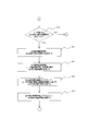
- FIG. 3 is a flowchart of the form output terminal management apparatus according to the embodiment.
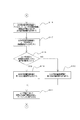
- FIG. 4 is a flowchart of the form output terminal management apparatus according to the embodiment.
- FIG. 5 is a flowchart of the form output terminal management apparatus according to the embodiment.
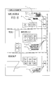
- FIG. 6 is an example of a display screen displayed on the display of the user terminal.
- a form output terminal changing system according to an embodiment of the present invention will be described with reference to FIGS. First, the configuration of the form output terminal changing system according to the present embodiment will be described with reference to FIG.
- the form output terminal changing system 1 includes a form output terminal that can change the output destination of a form by one or more user terminals 2, a plurality of output terminals 3, a Web server 4, and one or more user terminals 2. It comprises a change device 5 and a network 6 connecting them.
- the user terminal 2 is a general-purpose computer, and includes a CPU as an information processing unit, a RAM and a ROM as storage units, a display and I / O as output units, and a keyboard and pointing device as input units.
- the output terminal 3 is a printer 31.
- a printer server 32 is attached to the printer 31 and is connected to the network 6 via the printer server 3.
- the printer server 32 is a general-purpose computer similar to the user terminal 2.
- the printer 31 may be a network printer that can be directly connected to the network 6.
- the Web server 4 is a general-purpose computer similar to the user terminal 2.
- the Web server 4 is accessed from the user terminal 2 via the network 6, transmits information input from the user terminal 2 to the form output terminal changing device 5, and sends a processing request from the user terminal 2 to the form output terminal changing device. 5 to receive the processing result and transmit (reply) it to the user terminal 2.
- the form output terminal changing device 5 is a general-purpose computer similar to the user terminal 2.
- the form output terminal changing device 5 is installed with a form output terminal changing program for changing the setting of the output terminal 3 from which one or more user terminals 2 output a form.
- the form output terminal changing device 5 is configured such that the CPU executes this form output terminal changing program, whereby a transmission / reception unit (“form output destination location information transmission unit” of the present invention) 51, an information recognition unit 52, and output terminal information A storage unit 53, a form output processing unit 54, an output terminal information change unit 55, an output terminal arrangement information storage unit 56, an output terminal connection information storage unit 57, and a form output destination arrangement information generation unit 58 are realized.
- a transmission / reception unit (“form output destination location information transmission unit” of the present invention) 51, an information recognition unit 52, and output terminal information
- the transmission / reception unit 51 transmits / receives information to / from the Web server 4.
- the transmission / reception unit 51 transmits / receives information to / from the user terminal 2 and the output terminal 3 via the Web server 4.
- the information recognizing unit 52 recognizes information received from the Web server 4, determines which one of the form output processing unit 54, the output terminal information changing unit 55, or the form output destination arrangement information generating unit 58 is to be operated, and is necessary. Information is sent.
- the output terminal information storage unit 53 includes a plurality of user terminal identification information related to the user terminal 2 and a plurality of output terminals 3 that are set for each one or a group of forms as output destinations of the plurality of forms that the user terminal 2 outputs. Stores output terminal information. Specifically, the output terminal information includes the output terminal identification information of the output terminal 3, the form identification information of one or a group of forms that can be output, and the user terminal identification information of the user terminal 2 that has the authority to output the form. It consists of and. Then, the output terminal information storage unit 53 stores the output terminal information in association with the user terminal 2 and the output terminal 3 that can be output for each one or a group of forms.
- the form output processing unit 54 converts the form output information converted into a format that can be output by the output terminal 3 based on the information related to the form type transmitted together with the form output command from the information recognition unit 52 and the information for creating the form. Is generated.
- the form output processing unit 54 transmits this form output information to the information recognition unit 52.
- the output terminal information changing unit 55 changes one or more output terminal information in response to a change request for one or more output terminal information among a plurality of output terminal information from the user terminal 2. That is, the output terminal information changing unit 55 specifies the output terminal 3 to be changed from the user terminal identification information and the form identification information, and stores the output terminal information in the output terminal information storage unit 53 in association with the user terminal identification information and the form identification information. The output terminal identification information being changed is changed to the output terminal identification information transmitted together with the output terminal information change request.
- the output terminal arrangement information storage unit 56 includes output terminal installation area information related to an area where a plurality of output terminals 3 are installed, and user terminal position information that associates a position where the user terminal 2 is installed with a position in the output terminal arrangement area information.
- the output terminal position information that associates the position where each of the plurality of output terminals 3 is installed with the position in the output terminal arrangement area information is stored.
- the output terminal installation area information is a layout diagram illustrating terminals such as the user terminal 2 and the output terminal 3, a room where the terminal is installed, a desk, and the like.
- the user terminal position information and the output terminal position information are information relating to the coordinates (positions) of the user terminal 2 and the output terminal 3 on this layout drawing.
- the output terminal connection information storage unit 57 stores output terminal connection information related to the connection relationship between the user terminal 2 that has requested change of one or more output terminal information and at least one or more output terminals 3.
- the output terminal connection information is information related to a communication route between terminals such as the user terminal 2 and the output terminal 3, and if the terminals are communicated with each other by a wire such as a cable, This is information relating to the wiring route of the communication cable, and in the case of wireless communication such as a wireless LAN, it is information relating to the range of the wireless communication means.
- the form output destination arrangement information generation unit 58 is on an area associated with the position in the output terminal installation area information based on the output terminal position information.
- Form output destination arrangement information is generated in which an output terminal display that associates one or a group of forms with a plurality of output terminals 3 is added to the output terminal installation area information.
- the form output destination arrangement information generation unit 58 is based on one or more output terminal information changed in response to a change request for one or more output terminal information from the user terminal 2.
- the first output terminal display X that displays two or more output terminals 3 outputs a display that can be distinguished from the second output terminal display Y that displays a plurality of output terminals 3 based on other plurality of output terminal information.
- Form output destination arrangement information to be added to terminal installation information is generated.
- the form output destination arrangement information generating unit 58 generates form output destination arrangement information for adding the user terminal display A for displaying the user terminal 2 based on the user terminal identification information of the user terminal 2 to the output terminal installation information.
- the output terminal display is a display in which one or two or more output terminals 3 that can be output by the user terminal 2 that has requested transmission of a plurality of output terminal information can be identified for each one or two or more forms.
- the output terminal display is character information including names of various forms.
- the first output terminal display X is character information including the form name displayed in association with the position of the output terminal 3 before the change when the output destination of various forms is changed.
- the first output terminal display X displays the position associated with the position of the output terminal 3 when a form output from the output terminal 3 is newly added when the output destination of various forms is changed. This is character and graphic information in which a rectangular frame is added to the form name.
- the first output terminal display X displays the form at a position associated with the position of the output terminal 3 when the form output from the output terminal 3 is deleted when the output destination of various forms is changed. Character and graphic information with hatching and double strikethrough added to the name. These first output terminal displays X are displays added to the output terminal installation information for a predetermined period after being changed in response to a change request for one or more output terminal information from the user terminal 2.
- the first output terminal display X becomes the second output terminal display Y consisting of only the names of various forms after a predetermined period.
- the form output destination arrangement information generating unit 58 further includes an area associated with the position in the output terminal installation area information based on the output terminal connection information in response to a transmission request for one or more output terminal information from the user terminal 2
- Form output destination arrangement information for adding a connection relation display Z representing a connection relation between the user terminal 2 and at least one or more output terminals 3 to the output terminal installation area information is generated.
- connection relation display Z is graphic information displayed on the wiring route of the cable for communication if the terminals such as the user terminal 2 and the output terminal 3 are communicated by wire such as a cable.
- the graphic information is displayed by virtualizing the communication path for wireless communication.
- the network 6 is typically a LAN, WAN, Internet, telephone line, dedicated digital line, ATM, frame relay line, communication satellite line, cable TV line, data broadcasting radio line, or a combination thereof.
- the wired / wireless form is not limited.
- the user accesses the Web server 4 using the user terminal 2 and requests the Web server 4 for various processes.
- the Web server 4 recognizes the form output request via the transmission / reception unit 51 of the form output terminal changing device 5. It transmits to the part 52 (it is YES at step S1).
- the information recognition unit 52 transmits a form output command to the form output processing unit 54 based on the form output request (step S2), and causes the form output processing unit 54 to create a form.
- the form output processing unit 54 accesses the output terminal information storage unit 53 and acquires the output terminal identification information of the output terminal 3 based on the user terminal identification information and the form identification information of the user terminal 2 that has transmitted the output request. (Step S3).
- the form output processing unit 54 transmits the output terminal identification information of the output terminal 3 that outputs the form together with the form output information to the transmission / reception unit 51 via the information recognition unit 52, and the transmission / reception unit 51 sends the output terminal 3 to the output terminal 3.
- the form output information is transmitted to output the form (step S4).
- the Web server 4 changes the output terminal information as shown in FIG.
- the request is transmitted to the information recognition unit 52 via the transmission / reception unit 51 (NO in step S1, YES in step S5).
- the information recognition unit 52 transmits a change command to the output terminal information change unit 55, and causes the output terminal information change unit 55 to change the output terminal information (step S6).
- the output terminal information changing unit 55 receives the user terminal identification information, the form identification information, and the output terminal information of the user terminal 2 from the information recognition unit 52 (Step S7), accesses the output terminal information storage unit 53, and accesses the user terminal The output terminal 3 to be changed is specified from the user terminal identification information 2 and the form identification information (step S8). Then, the output terminal information changing unit 55 stores the output terminal information of the output terminal 3 (before change) stored in the output terminal information storage unit 53 in association with the user terminal identification information and the form identification information of the user terminal 3. The information is changed to the output terminal identification information of the output terminal 3 transmitted (want to be changed) together with the output terminal information change request (step S9).
- the Web server 4 When the user makes a transmission request for output terminal information that can be output from the user terminal 2, the Web server 4 sends the output terminal information transmission request via the transmission / reception unit 51 as shown in FIG. 4. It transmits to the information recognition part 52 (NO in step S1 and S5, YES in step S10).
- the information recognition unit 52 transmits an output terminal information transmission command to the form output destination arrangement information generation unit 58 based on the transmission request, and causes the form output destination arrangement information generation unit 58 to change the output terminal information (step S11).
- the form output destination arrangement information generation unit 58 receives the user terminal identification information, form identification information, and output terminal information of the user terminal 2 from the information recognition unit 52 (step S12), accesses the output terminal information storage unit 53, and The output terminal 3 to be changed is specified from the user terminal identification information and the form identification information of the user terminal 2 (step S13). Further, the form output destination arrangement information generating unit 58 accesses the output terminal arrangement information storage unit 56 and based on the user terminal identification information and the form identification information of the user terminal 2 that has transmitted the transmission request, the user terminal of the user terminal 2 The position information and the output terminal position information of the output terminal 3 are acquired (step S14), and the output terminal installation area information including at least the user terminal 2 and the output terminal 3 is acquired (step S15).
- the form output destination arrangement information generation unit 58 accesses the output terminal connection information storage unit 57 and outputs the output terminal based on the user identification information and the output terminal information of the user terminal 2 that has transmitted the transmission request. 3 is acquired (step S16).
- the form output destination arrangement information generating unit 58 adds the user terminal display A based on the user terminal information of the user terminal 2 and the connection relation display Z based on the output terminal connection information to the output terminal installation area information, thereby providing the form output destination arrangement.
- Information is generated (step S17).
- the form output destination arrangement information generation unit 58 further determines whether or not a predetermined period has elapsed since the output terminal information was changed in response to the output terminal information change request from the user terminal 2 (step S18).
- the first output terminal display X is selected as the output terminal display based on the output terminal information of the output terminal 3 (step S19), and if it has not elapsed (NO in step S18).
- the second output terminal display Y is selected as the output terminal display (step S20).
- the form output destination arrangement information generation unit 58 transmits the generated form output destination arrangement information to the transmission / reception unit 51 via the information recognition unit 52, and the transmission / reception unit 51 transmits the form output destination arrangement information to the user terminal 2. Then, it is displayed on the display of the user terminal 2 (step S21).
- the form output destination arrangement includes the characters “meter reading result slip” at the tip of the lead line drawn from the position of the output terminal PR11 (the area associated with the position on the form output destination arrangement information corresponding to the physical position of the output terminal).
- a first output terminal display X1 made up of a figure surrounded by a frame. This frame means that the output terminal PR11 has been added to the output destination of the meter reading result slip.
- the meter reading route confirmation list that has been changed from the user terminal 2 and has not been changed as a form to be output again from the user terminal 2 at the output terminal PR11 is surrounded by a frame. It is added to the form output destination arrangement information as the second output terminal display Y consisting of only the characters of the “meter reading route confirmation list”.
- the form output destination arrangement information includes a lead line drawn from the position of the output terminal PR11.
- the first output terminal display X2 consisting of the characters of the “collection result vote” and the figure surrounded by a frame is added to the tip of the terminal, and at the end of the lead line drawn from the position of the output terminal PR12
- a first output terminal display X3 is added, which is composed of a character of “collection result vote” and the entire character surrounded by a frame and a hatched figure. This hatching means that the output terminal PR12 is deleted from the output destination of the collection result vote.
- the form output destination arrangement information in order to display the position of the user terminal ID 13 that has requested transmission of the output terminal information, the form of “user terminal” is formed at the tip of the lead line drawn from the position of the user terminal ID 13. A user terminal display A is also added.
- the form output destination arrangement information corresponds to the wiring route of the LAN cable connecting the user terminal 2 and the output terminal 3 in order to display the output terminal connection information related to the connection relationship between the user terminal 2 and the output terminal 3.
- a connection relation display Z in which a dotted line is drawn at the position is also added.
- the output terminal information changing unit 55 changes the output terminal information in response to the output terminal information change request from the user terminal 2, and the output terminal 3 is output for each form by the form output destination arrangement information generating unit 58. Is output to the user terminal 2 from the transmitter / receiver 51.
- the user can grasp the respective positions of the plurality of output terminals 3 for one or a group of forms that can be output by the user terminal 2 from the form output destination arrangement information.
- the output terminal display is displayed for each of one or more forms that can be output from the output terminal 3, the user can easily grasp the output terminal 3 that is output for each form.
- the position of the output terminal 3 from which the user terminal 2 has requested the output terminal information change unit 55 to change the output terminal information is displayed on the first output terminal display X, and the user can display this first output terminal display.
- the position of the output terminal 3 changed by X can be grasped separately from the positions of the other output terminals 3, and the changed position of the output terminal 3 can be easily grasped.
- the first output terminal display X is displayed for a predetermined period, the user can check the position of the output terminal 3 changed by the first output terminal display X for a predetermined period. Since the output terminal installation area information to which the connection relation display Z is added as the connection relation between the user terminal 2 and at least one or more output terminals 3 is transmitted to the user terminal 2, the user displays the connection relation display Z.
- the output terminal 3 can be changed for reference.
- this invention is not limited to the structure of the said embodiment. That is, the present invention can take an embodiment as, for example, a system, apparatus, method, program, or storage medium, and may be specifically applied to a system including a plurality of devices. In addition, the present invention may be applied to an apparatus composed of a single device. Further, the present invention is not limited to the above-described effects. That is, the present invention can be variously modified without departing from the gist of the present invention.
- a software program in the embodiment, a program corresponding to the flowchart shown in the drawing
- the computer of the system or apparatus Is also achieved by reading and executing the supplied program code.
- the program code installed in the computer also implements the present invention.
- the present invention includes a computer program itself for realizing the functional processing of the present invention.
- a recording medium for supplying the program for example, floppy (registered trademark) disk, hard disk, optical disk, magneto-optical disk, MO, CD-ROM, CD-R, CD-RW, magnetic tape, nonvolatile memory card ROM, DVD (DVD-ROM, DVD-R), etc.
- a browser of a client computer is used to connect to a homepage on the Internet, and the computer program itself of the present invention or a compressed file including an automatic installation function is downloaded from the homepage to a recording medium such as a hard disk.
- a recording medium such as a hard disk.
- It can also be realized by dividing the program code constituting the program of the present invention into a plurality of files and downloading each file from a different homepage. That is, a WWW server that allows a plurality of users to download a program file for realizing the functional processing of the present invention on a computer is also included in the present invention.
- the OS running on the computer based on the instruction of the program is a part of the actual processing.
- the functions of the above-described embodiment can be realized by performing all of them and performing the processing.
- SYMBOLS 1 ... Form output terminal change system, 2 ... User terminal, 3 ... Output terminal, 31 ... Printer server, 32 ... Printer, 4 ... Web server, 5 ... Form output terminal change apparatus, 51 ... Transmission / reception part (form output destination arrangement information) (Transmission unit), 52 ... information recognition unit, 53 ... output terminal information storage unit, 54 ... form output processing unit, 55 ... output terminal information change unit, 56 ... output terminal arrangement information storage unit, 57 ... output terminal connection information storage unit 58 ... Form output destination arrangement information generation unit, 6 ... Network, A ... User terminal display, X ... First output terminal display (output terminal display), Y ... Second output terminal display (output terminal display), Z ... Connection display
Landscapes
- Engineering & Computer Science (AREA)
- Business, Economics & Management (AREA)
- Strategic Management (AREA)
- Entrepreneurship & Innovation (AREA)
- Human Resources & Organizations (AREA)
- Operations Research (AREA)
- Economics (AREA)
- Marketing (AREA)
- Data Mining & Analysis (AREA)
- Quality & Reliability (AREA)
- Tourism & Hospitality (AREA)
- Physics & Mathematics (AREA)
- General Business, Economics & Management (AREA)
- General Physics & Mathematics (AREA)
- Theoretical Computer Science (AREA)
- Management, Administration, Business Operations System, And Electronic Commerce (AREA)
- User Interface Of Digital Computer (AREA)
Abstract
ユーザ端末からの一又は二以上の出力端末情報の変更要求に応じて一又は二以上の出力端末情報を変更する出力端末情報変更部と、出力端末位置情報に基づく出力端末設置領域情報における位置に関連付けられた領域上に出力端末表示を出力端末設置領域情報に付加する帳票出力先配置情報を生成する帳票出力先配置情報生成部とを備える。
Description
本発明は、ネットワークを介して接続された一又は二以上のユーザ端末及び複数の出力端末を集中管理しているシステムにおいて、一又は二以上のユーザ端末から複数ある帳票が出力される出力端末を変更するための帳票出力端末変更装置、帳票出力端末変更システム、帳票出力端末変更方法及び帳票出力端末変更プログラムに関する。
従来より、一又は二以上のサーバにネットワークを介して一又は二以上のユーザ端末や複数の出力端末が接続され、これらの複数の端末がこのサーバによって集中管理されている。この集中管理システムにおいて、一又は二以上のユーザ端末が出力する帳票の出力先もサーバによって集中管理される場合がある。各ユーザは、一又は二以上のユーザ端末によってサーバにアクセスし、該サーバに対して帳票の出力要求を行うと、サーバが帳票の出力先を決定し、出力端末に帳票出力要求を行い、出力端末がこの帳票出力要求に従って帳票を出力する。
サーバが決定した出力端末によっては、故障や用紙切れなどによりユーザ側で出力端末として適さないことが容易にわかる場合であっても、ユーザ端末には、帳票を出力する出力端末を変更する権限がなく、ユーザは、サーバを管理する管理者に帳票の出力先を変更してほしい旨の依頼をしなければ変更することができなかった。
このような事情により、ユーザにもユーザ端末から帳票の出力先を変更する権限を与えられることが望まれていた。しかし、業務によって異なる形状や様式の帳票が取り扱われており、それぞれの帳票に応じて出力端末も使い分けられている。そのため、どの出力端末がどの帳票に対応しており、設定した出力端末がどこに設置されているのかをユーザがすべて把握することが困難である。そのことが帳票の出力先を変更する権限をユーザに付与する妨げとなっていた。
よって、本発明は、かかる事情に鑑み、ユーザ端末で帳票の出力先を変更できるようにするとともに、その変更後の出力端末の位置をユーザが容易に把握することができるようにユーザ端末に情報を提供する帳票出力端末変更装置、帳票出力端末変更システム、帳票出力端末変更方法及び帳票出力端末変更プログラムを提供することを課題とする。
本発明に係る帳票出力端末変更装置は、ユーザ端末が出力させる複数の帳票の出力先として一又は一群の帳票ごとに設定されている複数の出力端末に関する複数の出力端末情報を格納する出力端末情報格納部と、複数の出力端末が設置された領域に関する出力端末設置領域情報と、複数ある出力端末のそれぞれが設置された位置を出力端末配置領域情報における位置に対応付ける出力端末位置情報とを格納する出力端末配置情報格納部と、ユーザ端末からの複数ある出力端末情報のうちの一又は二以上の出力端末情報の変更要求に応じて一又は二以上の出力端末情報を変更する出力端末情報変更部と、ユーザ端末からの一又は二以上の出力端末情報の送信要求に応じて、出力端末位置情報に基づく出力端末設置領域情報における位置に関連付けられた領域上に一又は一群の帳票と複数ある出力端末のそれぞれとを対応付けて表す出力端末表示を出力端末設置領域情報に付加する帳票出力先配置情報を生成する帳票出力先配置情報生成部と、帳票出力先配置情報をユーザ端末に送信する帳票出力先配置情報送信部とを備えることを特徴とする。
ここで、本発明に係る帳票出力端末変更装置の一態様として、出力端末表示は、複数の出力端末情報の送信要求をしたユーザ端末が出力可能な一又は二以上の出力端末を一又は二以上の帳票ごとに識別可能な表示であることが好ましい。
また、本発明に係る帳票出力端末変更装置の他態様として、出力端末表示は、ユーザ端末からの一又は二以上の出力端末情報の変更要求に応じて変更された一又は二以上の出力端末情報に基づく一又は二以上の出力端末を表示する第一の出力端末表示と、他の複数の出力端末情報に基づく複数の出力端末を表示する第二の出力端末表示とを有し、帳票出力先配置情報生成部は、第一の出力端末表示を第二の出力端末表示と識別可能な表示となるように出力端末設置情報に付加する帳票出力先配置情報を生成することが好ましい。
また、本発明に係る帳票出力端末変更装置の他態様として、帳票出力先配置情報生成部は、ユーザ端末からの一又は二以上の出力端末情報の変更要求に応じて変更された後、所定期間、第一の出力端末表示を出力端末設置情報に付加する帳票出力先配置情報を生成することが好ましい。
また、本発明に係る帳票出力端末変更装置の他態様として、一又は二以上の出力端末情報を変更要求したユーザ端末と少なくとも一又は二以上の出力端末との接続関係に関する出力端末接続情報を格納する出力端末接続情報格納部を備え、帳票出力先配置情報生成部は、ユーザ端末からの一又は二以上の出力端末情報の送信要求に応じて、出力端末接続情報に基づく出力端末設置領域情報における位置に関連付けられた領域上にユーザ端末と少なくとも一又は二以上の出力端末との接続関係を表す接続関係表示を出力端末設置領域情報に付加する帳票出力先配置情報を生成することが好ましい。
また、本発明に係る帳票出力端末変更システムは、前述の帳票出力端末変更装置と、該帳票出力端末変更装置とネットワークを介して接続される一又は二以上のユーザ端末及び複数の出力端末とを備えることを特徴とする。
また、本発明に係る帳票出力端末変更方法は、前述の帳票出力端末変更装置を用いて複数の帳票を出力する複数ある出力端末を変更する帳票出力端末変更方法であって、ユーザ端末からの複数ある出力端末情報のうちの一又は二以上の出力端末情報の変更要求に応じて一又は二以上の出力端末情報を変更するステップと、ユーザ端末からの一又は二以上の出力端末情報の送信要求に応じて、出力端末位置情報に基づく出力端末設置領域情報における位置に関連付けられた領域上に一又は一群の帳票と複数ある出力端末のそれぞれとを対応付けて表す出力端末表示を出力端末設置領域情報に付加する帳票出力先配置情報を生成するステップと、帳票出力先配置情報をユーザ端末に送信するステップとを備えることを特徴とする。
また、本発明に係る帳票出力端末変更プログラムは、コンピュータを、ユーザ端末が出力させる複数の帳票の出力先として一又は一群の帳票ごとに設定されている複数の出力端末に関する複数の出力端末情報を格納する出力端末情報格納機能と、複数の出力端末が設置された領域に関する出力端末設置領域情報と、複数ある出力端末のそれぞれが設置された位置を出力端末配置領域情報における位置に対応付ける出力端末位置情報とを格納する出力端末配置情報格納機能と、ユーザ端末からの複数ある出力端末情報のうちの一又は二以上の出力端末情報の変更要求に応じて一又は二以上の出力端末情報を変更する出力端末情報変更機能と、ユーザ端末からの一又は二以上の出力端末情報の送信要求に応じて、出力端末位置情報に基づく出力端末設置領域情報における位置に関連付けられた領域上に一又は一群の帳票と複数ある出力端末のそれぞれとを対応付けて表す出力端末表示を出力端末設置領域情報に付加する帳票出力先配置情報を生成する帳票出力先配置情報生成機能と、帳票出力先配置情報をユーザ端末に送信する帳票出力先配置情報送信機能とを実現させることを特徴とする。
本発明の一実施形態に係る帳票出力端末変更システムについて、図1~図6を参照しつつ説明する。まず、本実施形態に係る帳票出力端末変更システムの構成について、図1を参照しつつ説明する。
帳票出力端末変更システム1は、一又は二以上のユーザ端末2と、複数の出力端末3と、Webサーバ4と、一又は二以上のユーザ端末2によって帳票の出力先を変更可能な帳票出力端末変更装置5と、これらを接続するネットワーク6とから構成される。
ユーザ端末2は、汎用コンピュータであり、情報処理部としてのCPUと、格納部としてのRAM及びROMと、出力部としてのディスプレイ及びI/Oと、入力部としてのキーボード及びポインティングデバイスとを備える。
出力端末3は、本実施形態では、プリンタ31である例を説明する。プリンタ31には、プリンタサーバ32が付属され、該プリンタサーバ3を介してネットワーク6に接続されている。プリンタサーバ32は、ユーザ端末2と同様の汎用コンピュータである。なお、プリンタ31は、直接ネットワーク6に接続することができるネットワークプリンタであってもよい。
Webサーバ4は、ユーザ端末2と同様の汎用コンピュータである。Webサーバ4は、ユーザ端末2からネットワーク6を介してアクセスされて、ユーザ端末2から入力される情報を帳票出力端末変更装置5に送信し、ユーザ端末2からの処理要求を帳票出力端末変更装置5に送信して処理結果を受信し、ユーザ端末2に送信(返信)する。
帳票出力端末変更装置5は、ユーザ端末2と同様の汎用コンピュータである。帳票出力端末変更装置5は、一又は二以上のユーザ端末2が帳票を出力する出力端末3の設定を変更するための帳票出力端末変更プログラムがインストールされている。帳票出力端末変更装置5は、この帳票出力端末変更プログラムをCPUが実行することにより、送受信部(本発明の「帳票出力先配置情報送信部」)51と、情報認識部52と、出力端末情報格納部53と、帳票出力処理部54と、出力端末情報変更部55と、出力端末配置情報格納部56と、出力端末接続情報格納部57と、帳票出力先配置情報生成部58とが実現される。
送受信部51は、Webサーバ4との情報の送受信を行う。そして、送受信部51は、このWebサーバ4を介して、ユーザ端末2、出力端末3と情報の送受信を行う。
情報認識部52は、Webサーバ4から受信する情報を認識して、帳票出力処理部54、出力端末情報変更部55又は帳票出力先配置情報生成部58の何れを動作させるかを決定し、必要な情報を送信する。
出力端末情報格納部53は、ユーザ端末2に関するユーザ端末識別情報と、ユーザ端末2が出力させる複数の帳票の出力先として一又は一群の帳票ごとに設定されている複数の出力端末3に関する複数の出力端末情報を格納する。出力端末情報は、具体的には、出力端末3の出力端末識別情報と、出力可能な一又は一群の帳票の帳票識別情報と、該帳票を出力する権限を有するユーザ端末2のユーザ端末識別情報とから構成されている。そして、出力端末情報格納部53は、出力端末情報を、ユーザ端末2と一又は一群の帳票ごとに出力可能な出力端末3を対応付けて格納する。
帳票出力処理部54は、情報認識部52からの帳票出力命令とともに送信される帳票種別に関する情報及びその帳票を作成するための情報に基づき出力端末3で出力可能なフォーマットに変換された帳票出力情報を生成する。帳票出力処理部54は、この帳票出力情報を情報認識部52に送信する。
出力端末情報変更部55は、ユーザ端末2からの複数ある出力端末情報のうちの一又は二以上の出力端末情報の変更要求に応じて一又は二以上の出力端末情報を変更する。つまり、出力端末情報変更部55は、ユーザ端末識別情報と帳票識別情報とから変更する出力端末3を特定し、出力端末情報格納部53にユーザ端末識別情報と帳票識別情報とに対応付けて格納されている出力端末識別情報を、出力端末情報の変更要求とともに送信されてきた出力端末識別情報に変更する。
出力端末配置情報格納部56は、複数の出力端末3が設置された領域に関する出力端末設置領域情報と、ユーザ端末2が設置された位置を出力端末配置領域情報における位置に対応付けるユーザ端末位置情報と、複数ある出力端末3のそれぞれが設置された位置を出力端末配置領域情報における位置に対応付ける出力端末位置情報とを格納する。出力端末設置領域情報は、具体的には、ユーザ端末2、出力端末3などの端末や該端末が設置される部屋、デスクなどが図示された配置図である。ユーザ端末位置情報及び出力端末位置情報は、この配置図上のユーザ端末2及び出力端末3の座標(位置)に関する情報である。
出力端末接続情報格納部57は、一又は二以上の出力端末情報を変更要求したユーザ端末2と少なくとも一又は二以上の出力端末3との接続関係に関する出力端末接続情報を格納する。出力端末接続情報は、具体的には、ユーザ端末2、出力端末3などの端末間の通信ルートに関する情報であって、端末間がケーブルなどの有線にて通信されている場合であれば、その通信用のケーブルの配線ルートに関する情報であり、無線LANなどの無線にて通信されている場合であれば、その無線通信手段の範囲に関する情報である。
帳票出力先配置情報生成部58は、ユーザ端末2からの一又は二以上の出力端末情報の送信要求に応じて、出力端末位置情報に基づく出力端末設置領域情報における位置に関連付けられた領域上に一又は一群の帳票と複数ある出力端末3のそれぞれとを対応付けて表す出力端末表示を出力端末設置領域情報に付加する帳票出力先配置情報を生成する。
帳票出力先配置情報生成部58は、図6に示すように、ユーザ端末2からの一又は二以上の出力端末情報の変更要求に応じて変更された一又は二以上の出力端末情報に基づく一又は二以上の出力端末3を表示する第一の出力端末表示Xを、他の複数の出力端末情報に基づく複数の出力端末3を表示する第二の出力端末表示Yと識別可能な表示を出力端末設置情報に付加する帳票出力先配置情報を生成する。また、帳票出力先配置情報生成部58は、ユーザ端末2のユーザ端末識別情報に基づくユーザ端末2を表示するユーザ端末表示Aを出力端末設置情報に付加する帳票出力先配置情報を生成する。
出力端末表示は、複数の出力端末情報の送信要求をしたユーザ端末2が出力可能な一又は二以上の出力端末3を一又は二以上の帳票ごとに識別可能な表示である。出力端末表示は、具体的には、各種帳票の名称からなる文字情報である。第一の出力端末表示Xは、各種帳票の出力先を変更したときに、変更前の出力端末3の位置に関連付けて表示される帳票の名称からなる文字情報である。例えば、第一の出力端末表示Xは、各種帳票の出力先を変更したときに、新たに出力端末3から出力される帳票が追加された場合、該出力端末3の位置に関連付けられた位置にその帳票名に矩形の枠が付加された文字及び図形情報である。また、第一の出力端末表示Xは、各種帳票の出力先を変更したときに、出力端末3から出力される帳票が削除された場合、該出力端末3の位置に関連付けられた位置にその帳票名にハッチングや二重取り消し線が付加された文字及び図形情報である。これらの第一の出力端末表示Xは、ユーザ端末2からの一又は二以上の出力端末情報の変更要求に応じて変更された後の所定期間、出力端末設置情報に付加される表示である。第一の出力端末表示Xは、所定期間経過後、各種帳票の名称のみからなる第二の出力端末表示Yとなる。
帳票出力先配置情報生成部58は、更に、ユーザ端末2からの一又は二以上の出力端末情報の送信要求に応じて、出力端末接続情報に基づく出力端末設置領域情報における位置に関連付けられた領域上にユーザ端末2と少なくとも一又は二以上の出力端末3との接続関係を表す接続関係表示Zを出力端末設置領域情報に付加する帳票出力先配置情報を生成する。
接続関係表示Zは、ユーザ端末2、出力端末3などの端末間がケーブルなどの有線にて通信されている場合であれば、その通信用のケーブルの配線ルートに表示した図形情報であり、無線LANなどの無線にて通信されている場合であれば、その無線通信される通信経路を仮想化して表示した図形情報である。
ネットワーク6は、典型的にはLANやWAN、インターネット、電話回線、専用デジタル回線、ATMやフレームリレー回線、通信衛星回線、ケーブルテレビ回線、データ放送用の無線回線等のいずれか、またはこれらの組み合わせにより実現されるいわゆる通信ネットワークであり、相互のデータの送受信が可能であれば、有線/無線の形態は問わない。
次に、本実施形態に係る帳票出力端末変更システムの作用について、図1~図6を参照しつつ説明する。
まず、ユーザは、ユーザ端末2を利用してWebサーバ4にアクセスし、Webサーバ4に対して各種処理を要求する。例えば、図2に示されているように、ユーザがユーザ端末2から帳票出力要求を行うと、Webサーバ4は、この帳票出力要求を帳票出力端末変更装置5の送受信部51を介して情報認識部52に送信する(ステップS1でYES)。情報認識部52は、帳票出力要求に基づいて帳票出力処理部54に帳票出力命令を送信して(ステップS2)、帳票出力処理部54に帳票を作成させる。そして、帳票出力処理部54は、出力端末情報格納部53にアクセスして、出力要求を送信したユーザ端末2のユーザ端末識別情報と帳票識別情報とに基づき出力端末3の出力端末識別情報を取得する(ステップS3)。帳票出力処理部54は、帳票出力情報とともに、その帳票を出力させる出力端末3の出力端末識別情報を情報認識部52を介して送受信部51に送信し、送受信部51は、出力端末3に対して帳票出力情報を送信して、帳票を出力させる(ステップS4)。
また、ユーザがユーザ端末2から帳票を出力可能な出力端末3を変更する出力端末情報の変更要求を行うと、Webサーバ4は、図3に示されているように、この出力端末情報の変更要求を送受信部51を介して情報認識部52に送信する(ステップS1でNO、ステップS5でYES)。情報認識部52は、この変更要求に基づき出力端末情報変更部55に変更命令を送信して、出力端末情報変更部55に出力端末情報を変更させる(ステップS6)。
出力端末情報変更部55は、情報認識部52からユーザ端末2のユーザ端末識別情報と帳票識別情報と出力端末情報を受信し(ステップS7)、出力端末情報格納部53にアクセスして、ユーザ端末2のユーザ端末識別情報と帳票識別情報とから変更する出力端末3を特定する(ステップS8)。そして、出力端末情報変更部55は、出力端末情報格納部53にユーザ端末3のユーザ端末識別情報と帳票識別情報とに対応付けて格納されている(変更前の)出力端末3の出力端末識別情報を、出力端末情報の変更要求とともに送信されてきた(変更したい)出力端末3の出力端末識別情報に変更する(ステップS9)。
また、ユーザがユーザ端末2から出力可能な出力端末情報の送信要求を行うと、Webサーバ4は、図4に示されているように、この出力端末情報の送信要求を送受信部51を介して情報認識部52に送信する(ステップS1及びS5でNO、ステップS10でYES)。情報認識部52は、送信要求に基づき帳票出力先配置情報生成部58に出力端末情報の送信命令を送信して、帳票出力先配置情報生成部58に出力端末情報を変更させる(ステップS11)。
帳票出力先配置情報生成部58は、情報認識部52からユーザ端末2のユーザ端末識別情報と帳票識別情報と出力端末情報を受信し(ステップS12)、出力端末情報格納部53にアクセスして、ユーザ端末2のユーザ端末識別情報と帳票識別情報とから変更する出力端末3を特定する(ステップS13)。更に、帳票出力先配置情報生成部58は、出力端末配置情報格納部56にアクセスして、送信要求を送信したユーザ端末2のユーザ端末識別情報と帳票識別情報とに基づきユーザ端末2のユーザ端末位置情報と出力端末3の出力端末位置情報を取得する(ステップS14)とともに、ユーザ端末2と出力端末3とが少なくとも含まれる出力端末設置領域情報を取得する(ステップS15)。
帳票出力先配置情報生成部58は、図5に示すように、出力端末接続情報格納部57にアクセスして、送信要求を送信したユーザ端末2のユーザ識別情報と出力端末情報とに基づき出力端末3の出力端末接続情報を取得する(ステップS16)。帳票出力先配置情報生成部58は、出力端末設置領域情報にユーザ端末2のユーザ端末情報に基づくユーザ端末表示Aと、出力端末接続情報に基づく接続関係表示Zとを付加して帳票出力先配置情報を生成する(ステップS17)。帳票出力先配置情報生成部58は、更に、ユーザ端末2からの出力端末情報の変更要求に応じて出力端末情報を変更されてから所定期間経過しているかを判定し(ステップS18)、経過していれば(ステップS18でYES)、出力端末3の出力端末情報に基づく出力端末表示として、第一の出力端末表示Xを選択し(ステップS19)、経過していなければ(ステップS18でNO)、出力端末表示として、第二の出力端末表示Yを選択する(ステップS20)。帳票出力先配置情報生成部58は、生成した帳票出力先配置情報を情報認識部52を介して送受信部51に送信し、送受信部51は、ユーザ端末2に対して帳票出力先配置情報を送信して、ユーザ端末2のディスプレイ上に表示させる(ステップS21)。
ユーザ端末2のディスプレイ上では、例えば、図6に示されているように、ユーザ端末2から出力端末PR11(3)で出力する帳票として新たに検針結果票を追加した場合に、帳票出力先配置情報には、出力端末PR11の位置(出力端末の物理的な位置に対応した帳票出力先配置情報上における位置に関連付けられた領域)から引き出された引き出し線の先に「検針結果票」の文字と文字全体を枠で囲まれた図形とからなる第一の出力端末表示X1が付加されている。この枠は、検針結果票の出力先に出力端末PR11が追加されたことを意味する。更に、ユーザ端末2から変更されてから所定期間経過しており、ユーザ端末2から改めて出力端末PR11で出力する帳票として変更されていない検針員順路確認一覧表については、文字全体を枠で囲まれていない「検針員順路確認一覧表」の文字のみからなる第二の出力端末表示Yとして帳票出力先配置情報に付加されている。
また、ユーザ端末2から出力端末PR12(3)で出力されていた集金結果票を、出力端末PR11に振り替えた場合に、帳票出力先配置情報には、出力端末PR11の位置から引き出された引き出し線の先に「集金結果票」の文字と文字全体を枠で囲まれた図形とからなる第一の出力端末表示X2が付加されるとともに、出力端末PR12の位置から引き出された引き出し線の先に「集金結果票」の文字と文字全体を枠で囲まれ、全体にハッチングが付された図形とからなる第一の出力端末表示X3が付加される。このハッチングは、集金結果票の出力先から出力端末PR12が削除されたことを意味する。
また、検針員(社員)エリアの出力端末PR21に表示されている「集金変更通知結果票」及び「集金員登録確認票」は、今回、ユーザ端末2から変更した帳票ではないが、前回、ユーザ端末2から変更された帳票であり、変更されてから所定期間経過していないため、「集金変更通知結果票」及び「集金員登録確認票」からなる文字に下線が付された第一の出力端末表示X4が付加される。
帳票出力先配置情報には、出力端末情報の送信要求をしたユーザ端末ID13の位置を表示するために、該ユーザ端末ID13の位置から引き出された引き出し線の先に「ユーザ端末」の文字からなるユーザ端末表示Aも付加されている。また、帳票出力先配置情報には、ユーザ端末2と出力端末3との接続関係に関する出力端末接続情報を表示するために、ユーザ端末2と出力端末3とを接続するLANケーブルの配線ルートに対応した位置に点線が引かれた接続関係表示Zも付加されている。
このように、出力端末情報変更部55がユーザ端末2からの出力端末情報の変更要求に応じて出力端末情報を変更し、帳票出力先配置情報生成部58によって帳票ごとに出力される出力端末3の位置が出力端末表示で表された帳票出力先配置情報が送受信部51からユーザ端末2に送信される。ユーザは、この帳票出力先配置情報からユーザ端末2で出力可能な一又は一群の帳票ごとの複数ある出力端末3のそれぞれの位置を把握できるようになる。
また、出力端末3から出力可能な一又は二以上の帳票ごとに出力端末表示が表示されるため、ユーザは、帳票ごとに出力される出力端末3を容易に把握することができるようになる。ユーザ端末2が出力端末情報変更部55に対して出力端末情報の変更要求を行った出力端末3の位置は、第一の出力端末表示Xで表示され、ユーザは、この第一の出力端末表示Xによって変更された出力端末3の位置を他の出力端末3の位置と区別して把握することができ、変更した出力端末3の位置を容易に把握することができるようになる。第一の出力端末表示Xが所定期間表示されるため、ユーザは、所定期間の間、第一の出力端末表示Xによって変更した出力端末3の位置を確認することができるようになる。ユーザ端末2と少なくとも一又は二以上の出力端末3との接続関係が接続関係表示Zが付加された出力端末設置領域情報がユーザ端末2に送信されるため、ユーザは、この接続関係表示Zを参考に出力端末3を変更することができるようになる。
なお、本発明は、上記実施形態の構成に限定されるものではない。つまり、本発明は、例えば、システム、装置、方法、プログラムもしくは記憶媒体等としての実施態様をとることが可能であり、具体的には、複数の機器から構成されるシステムに適用しても良いし、また、一つの機器からなる装置に適用しても良い。また、本発明は、上記した作用効果に限定されるものでもない。つまり、本発明は、本発明の要旨を逸脱しない範囲で種々の変更が可能である。
なお、本発明は、前述した実施形態の機能を実現するソフトウェアのプログラム(実施形態では図に示すフローチャートに対応したプログラム)を、システムあるいは装置に直接あるいは遠隔から供給し、そのシステムあるいは装置のコンピュータが該供給されたプログラムコードを読み出して実行することによっても達成される場合を含む。
従って、本発明の機能処理をコンピュータで実現するために、該コンピュータにインストールされるプログラムコード自体も本発明を実現するものである。つまり、本発明は、本発明の機能処理を実現するためのコンピュータプログラム自体も含まれる。
プログラムを供給するための記録媒体としては、例えば、フロッピー(登録商標)ディスク、ハードディスク、光ディスク、光磁気ディスク、MO、CD-ROM、CD-R、CD-RW、磁気テープ、不揮発性のメモリカード、ROM、DVD(DVD-ROM,DVD-R)などがある。
プログラムの供給方法としては、クライアントコンピュータのブラウザを用いてインターネットのホームページに接続し、該ホームページから本発明のコンピュータプログラムそのもの、もしくは圧縮され自動インストール機能を含むファイルをハードディスク等の記録媒体にダウンロードすることによっても供給できる。また、本発明のプログラムを構成するプログラムコードを複数のファイルに分割し、それぞれのファイルを異なるホームページからダウンロードすることによっても実現可能である。つまり、本発明の機能処理をコンピュータで実現するためのプログラムファイルを複数のユーザに対してダウンロードさせるWWWサーバも、本発明に含まれるものである。
また、コンピュータが、読み出したプログラムを実行することによって、前述した実施形態の機能が実現される他、そのプログラムの指示に基づき、コンピュータ上で稼動しているOSなどが、実際の処理の一部または全部を行ない、その処理によっても前述した実施形態の機能が実現され得る。
1…帳票出力端末変更システム、2…ユーザ端末、3…出力端末、31…プリンタサーバ、32…プリンタ、4…Webサーバ、5…帳票出力端末変更装置、51…送受信部(帳票出力先配置情報送信部)、52…情報認識部、53…出力端末情報格納部、54…帳票出力処理部、55…出力端末情報変更部、56…出力端末配置情報格納部、57…出力端末接続情報格納部、58…帳票出力先配置情報生成部、6…ネットワーク、A…ユーザ端末表示、X…第一の出力端末表示(出力端末表示)、Y…第二の出力端末表示(出力端末表示)、Z…接続関係表示
Claims (8)
- ユーザ端末が出力させる複数の帳票の出力先として一又は一群の帳票ごとに設定されている複数の出力端末に関する複数の出力端末情報を格納する出力端末情報格納部と、
前記複数の出力端末が設置された領域に関する出力端末設置領域情報と、前記複数ある出力端末のそれぞれが設置された位置を前記出力端末配置領域情報における位置に対応付ける出力端末位置情報とを格納する出力端末配置情報格納部と、
前記ユーザ端末からの前記複数ある出力端末情報のうちの一又は二以上の出力端末情報の変更要求に応じて前記一又は二以上の出力端末情報を変更する出力端末情報変更部と、
前記ユーザ端末からの前記一又は二以上の出力端末情報の送信要求に応じて、前記出力端末位置情報に基づく前記出力端末設置領域情報における位置に関連付けられた領域上に前記一又は一群の帳票と前記複数ある出力端末のそれぞれとを対応付けて表す出力端末表示を前記出力端末設置領域情報に付加する帳票出力先配置情報を生成する帳票出力先配置情報生成部と、
前記帳票出力先配置情報を前記ユーザ端末に送信する帳票出力先配置情報送信部と
を備える帳票出力端末変更装置。 - 前記出力端末表示は、前記複数の出力端末情報の送信要求をした前記ユーザ端末が出力可能な前記一又は二以上の出力端末を前記一又は二以上の帳票ごとに識別可能な表示である請求項1に記載の帳票出力端末変更装置。
- 前記出力端末表示は、前記ユーザ端末からの前記一又は二以上の出力端末情報の変更要求に応じて変更された前記一又は二以上の出力端末情報に基づく前記一又は二以上の出力端末を表示する第一の出力端末表示と、他の前記複数の出力端末情報に基づく前記複数の出力端末を表示する第二の出力端末表示とを有し、
前記帳票出力先配置情報生成部は、前記第一の出力端末表示を前記第二の出力端末表示と識別可能な表示となるように前記出力端末設置情報に付加する前記帳票出力先配置情報を生成する請求項1又は請求項2に記載の帳票出力端末変更装置。 - 前記帳票出力先配置情報生成部は、前記ユーザ端末からの前記一又は二以上の出力端末情報の変更要求に応じて変更された後、所定期間、前記第一の出力端末表示を前記出力端末設置情報に付加する前記帳票出力先配置情報を生成する請求項3に記載の帳票出力端末変更装置。
- 前記一又は二以上の出力端末情報を変更要求した前記ユーザ端末と少なくとも前記一又は二以上の出力端末との接続関係に関する出力端末接続情報を格納する出力端末接続情報格納部を備え、
前記帳票出力先配置情報生成部は、前記ユーザ端末からの前記一又は二以上の出力端末情報の送信要求に応じて、前記出力端末接続情報に基づく前記出力端末設置領域情報における位置に関連付けられた領域上に前記ユーザ端末と少なくとも前記一又は二以上の出力端末との接続関係を表す接続関係表示を前記出力端末設置領域情報に付加する前記帳票出力先配置情報を生成する請求項1~請求項4のいずれか1項に記載の帳票出力端末変更装置。 - 請求項1~請求項5のいずれか1項に記載の帳票出力端末変更装置と、
該帳票出力端末変更装置とネットワークを介して接続される前記一又は二以上のユーザ端末及び前記複数の出力端末と
を備える帳票出力端末変更システム。 - 請求項1~請求項5のいずれか1項に記載の帳票出力端末変更装置を用いて前記複数の帳票を出力する前記複数ある出力端末を変更する帳票出力端末変更方法であって、
前記ユーザ端末からの前記複数ある出力端末情報のうちの一又は二以上の出力端末情報の変更要求に応じて前記一又は二以上の出力端末情報を変更するステップと、
前記ユーザ端末からの前記一又は二以上の出力端末情報の送信要求に応じて、前記出力端末位置情報に基づく前記出力端末設置領域情報における位置に関連付けられた領域上に前記一又は一群の帳票と前記複数ある出力端末のそれぞれとを対応付けて表す出力端末表示を前記出力端末設置領域情報に付加する帳票出力先配置情報を生成するステップと、
前記帳票出力先配置情報を前記ユーザ端末に送信するステップと
を備える帳票出力端末変更方法。 - コンピュータを、
ユーザ端末が出力させる複数の帳票の出力先として一又は一群の帳票ごとに設定されている複数の出力端末に関する複数の出力端末情報を格納する出力端末情報格納機能と、
前記複数の出力端末が設置された領域に関する出力端末設置領域情報と、前記複数ある出力端末のそれぞれが設置された位置を前記出力端末配置領域情報における位置に対応付ける出力端末位置情報とを格納する出力端末配置情報格納機能と、
前記ユーザ端末からの前記複数ある出力端末情報のうちの一又は二以上の出力端末情報の変更要求に応じて前記一又は二以上の出力端末情報を変更する出力端末情報変更機能と、
前記ユーザ端末からの前記一又は二以上の出力端末情報の送信要求に応じて、前記出力端末位置情報に基づく前記出力端末設置領域情報における位置に関連付けられた領域上に前記一又は一群の帳票と前記複数ある出力端末のそれぞれとを対応付けて表す出力端末表示を前記出力端末設置領域情報に付加する帳票出力先配置情報を生成する帳票出力先配置情報生成機能と、
前記帳票出力先配置情報を前記ユーザ端末に送信する帳票出力先配置情報送信機能と
を実現させるコンピュータ読取可能な帳票出力端末変更プログラム。
Priority Applications (2)
| Application Number | Priority Date | Filing Date | Title |
|---|---|---|---|
| JP2013527813A JP5389300B1 (ja) | 2012-10-26 | 2012-10-26 | 帳票出力端末変更装置、帳票出力端末変更システム、帳票出力端末変更方法及び帳票出力端末変更プログラム |
| PCT/JP2012/077702 WO2014064829A1 (ja) | 2012-10-26 | 2012-10-26 | 帳票出力端末変更装置、帳票出力端末変更システム、帳票出力端末変更方法及び帳票出力端末変更プログラム |
Applications Claiming Priority (1)
| Application Number | Priority Date | Filing Date | Title |
|---|---|---|---|
| PCT/JP2012/077702 WO2014064829A1 (ja) | 2012-10-26 | 2012-10-26 | 帳票出力端末変更装置、帳票出力端末変更システム、帳票出力端末変更方法及び帳票出力端末変更プログラム |
Publications (1)
| Publication Number | Publication Date |
|---|---|
| WO2014064829A1 true WO2014064829A1 (ja) | 2014-05-01 |
Family
ID=50036696
Family Applications (1)
| Application Number | Title | Priority Date | Filing Date |
|---|---|---|---|
| PCT/JP2012/077702 Ceased WO2014064829A1 (ja) | 2012-10-26 | 2012-10-26 | 帳票出力端末変更装置、帳票出力端末変更システム、帳票出力端末変更方法及び帳票出力端末変更プログラム |
Country Status (2)
| Country | Link |
|---|---|
| JP (1) | JP5389300B1 (ja) |
| WO (1) | WO2014064829A1 (ja) |
Citations (7)
| Publication number | Priority date | Publication date | Assignee | Title |
|---|---|---|---|---|
| JPH03150614A (ja) * | 1989-11-08 | 1991-06-27 | Hitachi Ltd | 共有資源管理方法および情報処理システム |
| JPH03252722A (ja) * | 1990-03-01 | 1991-11-12 | Nec Corp | 帳票出力先プリンタ端末の選定方式 |
| JPH09167067A (ja) * | 1995-12-18 | 1997-06-24 | Nec Corp | 帳票出力宛先プリンタ選択運用システムおよび帳票出力宛先プリンタ選択方法 |
| JPH10214167A (ja) * | 1997-01-30 | 1998-08-11 | Nec Corp | 帳票出力方式 |
| JP2002163091A (ja) * | 2000-11-27 | 2002-06-07 | Nec Corp | 帳票印刷システム |
| JP2003345555A (ja) * | 2002-05-28 | 2003-12-05 | Chibagin Computer Service Kk | 帳票出力管理システム及びこれを実現するためのコンピュータプログラム |
| JP2007233500A (ja) * | 2006-02-28 | 2007-09-13 | Hitachi Ltd | 帳票出力処理システム |
-
2012
- 2012-10-26 JP JP2013527813A patent/JP5389300B1/ja not_active Expired - Fee Related
- 2012-10-26 WO PCT/JP2012/077702 patent/WO2014064829A1/ja not_active Ceased
Patent Citations (7)
| Publication number | Priority date | Publication date | Assignee | Title |
|---|---|---|---|---|
| JPH03150614A (ja) * | 1989-11-08 | 1991-06-27 | Hitachi Ltd | 共有資源管理方法および情報処理システム |
| JPH03252722A (ja) * | 1990-03-01 | 1991-11-12 | Nec Corp | 帳票出力先プリンタ端末の選定方式 |
| JPH09167067A (ja) * | 1995-12-18 | 1997-06-24 | Nec Corp | 帳票出力宛先プリンタ選択運用システムおよび帳票出力宛先プリンタ選択方法 |
| JPH10214167A (ja) * | 1997-01-30 | 1998-08-11 | Nec Corp | 帳票出力方式 |
| JP2002163091A (ja) * | 2000-11-27 | 2002-06-07 | Nec Corp | 帳票印刷システム |
| JP2003345555A (ja) * | 2002-05-28 | 2003-12-05 | Chibagin Computer Service Kk | 帳票出力管理システム及びこれを実現するためのコンピュータプログラム |
| JP2007233500A (ja) * | 2006-02-28 | 2007-09-13 | Hitachi Ltd | 帳票出力処理システム |
Also Published As
| Publication number | Publication date |
|---|---|
| JPWO2014064829A1 (ja) | 2016-09-05 |
| JP5389300B1 (ja) | 2014-01-15 |
Similar Documents
| Publication | Publication Date | Title |
|---|---|---|
| JP2008532119A5 (ja) | ||
| JP2011134159A5 (ja) | 取引処理システム及びプログラム | |
| JP2013152666A (ja) | 管理システム、画像形成装置、管理システムの制御方法、画像形成装置の制御方法、プログラム | |
| JP2019121285A (ja) | 構成変更管理装置、構成変更管理方法、及びプログラム | |
| JP6763654B2 (ja) | ネットワークシステム、サーバ、プログラム、および端末 | |
| CN102103475A (zh) | 打印任务管理装置、系统及方法 | |
| US10963536B2 (en) | Information processing system and information processing method | |
| JP2013145436A (ja) | Api用制御装置、api用制御方法およびプログラム | |
| JP2014238815A (ja) | 情報処理システム、情報提供方法、端末装置およびプログラム | |
| JP2007026015A (ja) | 情報表示方法 | |
| JP6192339B2 (ja) | 文書管理システム、管理装置、文書管理方法およびコンピュータプログラム | |
| JP5389300B1 (ja) | 帳票出力端末変更装置、帳票出力端末変更システム、帳票出力端末変更方法及び帳票出力端末変更プログラム | |
| JP2009205473A (ja) | 処理状態管理装置、処理状態管理方法およびプログラム | |
| JP7047504B2 (ja) | ジョブシステム、ジョブ実行方法、情報処理装置、プログラム | |
| JP2004504636A (ja) | 電光板運営システム及びその運営方法 | |
| JP5832269B2 (ja) | タイムスタンプ付与装置 | |
| JP2021114104A (ja) | 情報管理支援装置および情報管理支援プログラム | |
| JP4802075B2 (ja) | コンテンツ送信装置及びコンテンツ送信方法 | |
| JP2015060498A (ja) | 管理サーバ及び情報提供システム | |
| JP2019105911A (ja) | メンテナンスデータ提供システム、サーバ及び情報処理プログラム | |
| US20210390646A1 (en) | Procedure reporting system for industrial property rights | |
| JP6364569B1 (ja) | 情報処理プログラム、情報処理装置、及び情報処理方法 | |
| KR20110064158A (ko) | 전자방명록 제공방법 | |
| JP2018190023A (ja) | IoT(Internet Of Things)におけるデータ送受信システム | |
| JP7366168B2 (ja) | プログラム、情報処理装置、情報処理システム、情報処理方法 |
Legal Events
| Date | Code | Title | Description |
|---|---|---|---|
| ENP | Entry into the national phase |
Ref document number: 2013527813 Country of ref document: JP Kind code of ref document: A |
|
| 121 | Ep: the epo has been informed by wipo that ep was designated in this application |
Ref document number: 12887209 Country of ref document: EP Kind code of ref document: A1 |
|
| NENP | Non-entry into the national phase |
Ref country code: DE |
|
| 122 | Ep: pct application non-entry in european phase |
Ref document number: 12887209 Country of ref document: EP Kind code of ref document: A1 |