WO2014058008A1 - 船体抵抗低減システムおよび船体の抵抗低減方法 - Google Patents
船体抵抗低減システムおよび船体の抵抗低減方法 Download PDFInfo
- Publication number
- WO2014058008A1 WO2014058008A1 PCT/JP2013/077583 JP2013077583W WO2014058008A1 WO 2014058008 A1 WO2014058008 A1 WO 2014058008A1 JP 2013077583 W JP2013077583 W JP 2013077583W WO 2014058008 A1 WO2014058008 A1 WO 2014058008A1
- Authority
- WO
- WIPO (PCT)
- Prior art keywords
- compressor
- exhaust
- exhaust turbine
- exhaust gas
- air
- Prior art date
- Legal status (The legal status is an assumption and is not a legal conclusion. Google has not performed a legal analysis and makes no representation as to the accuracy of the status listed.)
- Ceased
Links
Images

Classifications
-
- B—PERFORMING OPERATIONS; TRANSPORTING
- B63—SHIPS OR OTHER WATERBORNE VESSELS; RELATED EQUIPMENT
- B63B—SHIPS OR OTHER WATERBORNE VESSELS; EQUIPMENT FOR SHIPPING
- B63B1/00—Hydrodynamic or hydrostatic features of hulls or of hydrofoils
- B63B1/32—Other means for varying the inherent hydrodynamic characteristics of hulls
- B63B1/34—Other means for varying the inherent hydrodynamic characteristics of hulls by reducing surface friction
- B63B1/38—Other means for varying the inherent hydrodynamic characteristics of hulls by reducing surface friction using air bubbles or air layers gas filled volumes
-
- F—MECHANICAL ENGINEERING; LIGHTING; HEATING; WEAPONS; BLASTING
- F01—MACHINES OR ENGINES IN GENERAL; ENGINE PLANTS IN GENERAL; STEAM ENGINES
- F01N—GAS-FLOW SILENCERS OR EXHAUST APPARATUS FOR MACHINES OR ENGINES IN GENERAL; GAS-FLOW SILENCERS OR EXHAUST APPARATUS FOR INTERNAL-COMBUSTION ENGINES
- F01N5/00—Exhaust or silencing apparatus combined or associated with devices profiting by exhaust energy
- F01N5/04—Exhaust or silencing apparatus combined or associated with devices profiting by exhaust energy the devices using kinetic energy
-
- F—MECHANICAL ENGINEERING; LIGHTING; HEATING; WEAPONS; BLASTING
- F02—COMBUSTION ENGINES; HOT-GAS OR COMBUSTION-PRODUCT ENGINE PLANTS
- F02B—INTERNAL-COMBUSTION PISTON ENGINES; COMBUSTION ENGINES IN GENERAL
- F02B37/00—Engines characterised by provision of pumps driven at least for part of the time by exhaust
- F02B37/001—Engines characterised by provision of pumps driven at least for part of the time by exhaust using exhaust drives arranged in parallel
-
- F—MECHANICAL ENGINEERING; LIGHTING; HEATING; WEAPONS; BLASTING
- F02—COMBUSTION ENGINES; HOT-GAS OR COMBUSTION-PRODUCT ENGINE PLANTS
- F02B—INTERNAL-COMBUSTION PISTON ENGINES; COMBUSTION ENGINES IN GENERAL
- F02B37/00—Engines characterised by provision of pumps driven at least for part of the time by exhaust
- F02B37/007—Engines characterised by provision of pumps driven at least for part of the time by exhaust with exhaust-driven pumps arranged in parallel, e.g. at least one pump supplying alternatively
-
- F—MECHANICAL ENGINEERING; LIGHTING; HEATING; WEAPONS; BLASTING
- F02—COMBUSTION ENGINES; HOT-GAS OR COMBUSTION-PRODUCT ENGINE PLANTS
- F02B—INTERNAL-COMBUSTION PISTON ENGINES; COMBUSTION ENGINES IN GENERAL
- F02B63/00—Adaptations of engines for driving pumps, hand-held tools or electric generators; Portable combinations of engines with engine-driven devices
- F02B63/04—Adaptations of engines for driving pumps, hand-held tools or electric generators; Portable combinations of engines with engine-driven devices for electric generators
-
- F—MECHANICAL ENGINEERING; LIGHTING; HEATING; WEAPONS; BLASTING
- F02—COMBUSTION ENGINES; HOT-GAS OR COMBUSTION-PRODUCT ENGINE PLANTS
- F02G—HOT GAS OR COMBUSTION-PRODUCT POSITIVE-DISPLACEMENT ENGINE PLANTS; USE OF WASTE HEAT OF COMBUSTION ENGINES; NOT OTHERWISE PROVIDED FOR
- F02G5/00—Profiting from waste heat of combustion engines, not otherwise provided for
- F02G5/02—Profiting from waste heat of exhaust gases
-
- B—PERFORMING OPERATIONS; TRANSPORTING
- B63—SHIPS OR OTHER WATERBORNE VESSELS; RELATED EQUIPMENT
- B63B—SHIPS OR OTHER WATERBORNE VESSELS; EQUIPMENT FOR SHIPPING
- B63B1/00—Hydrodynamic or hydrostatic features of hulls or of hydrofoils
- B63B1/32—Other means for varying the inherent hydrodynamic characteristics of hulls
- B63B1/34—Other means for varying the inherent hydrodynamic characteristics of hulls by reducing surface friction
- B63B1/38—Other means for varying the inherent hydrodynamic characteristics of hulls by reducing surface friction using air bubbles or air layers gas filled volumes
- B63B2001/385—Other means for varying the inherent hydrodynamic characteristics of hulls by reducing surface friction using air bubbles or air layers gas filled volumes using exhaust gas
-
- F—MECHANICAL ENGINEERING; LIGHTING; HEATING; WEAPONS; BLASTING
- F02—COMBUSTION ENGINES; HOT-GAS OR COMBUSTION-PRODUCT ENGINE PLANTS
- F02B—INTERNAL-COMBUSTION PISTON ENGINES; COMBUSTION ENGINES IN GENERAL
- F02B63/00—Adaptations of engines for driving pumps, hand-held tools or electric generators; Portable combinations of engines with engine-driven devices
- F02B63/06—Adaptations of engines for driving pumps, hand-held tools or electric generators; Portable combinations of engines with engine-driven devices for pumps
-
- Y—GENERAL TAGGING OF NEW TECHNOLOGICAL DEVELOPMENTS; GENERAL TAGGING OF CROSS-SECTIONAL TECHNOLOGIES SPANNING OVER SEVERAL SECTIONS OF THE IPC; TECHNICAL SUBJECTS COVERED BY FORMER USPC CROSS-REFERENCE ART COLLECTIONS [XRACs] AND DIGESTS
- Y02—TECHNOLOGIES OR APPLICATIONS FOR MITIGATION OR ADAPTATION AGAINST CLIMATE CHANGE
- Y02T—CLIMATE CHANGE MITIGATION TECHNOLOGIES RELATED TO TRANSPORTATION
- Y02T10/00—Road transport of goods or passengers
- Y02T10/10—Internal combustion engine [ICE] based vehicles
- Y02T10/12—Improving ICE efficiencies
-
- Y—GENERAL TAGGING OF NEW TECHNOLOGICAL DEVELOPMENTS; GENERAL TAGGING OF CROSS-SECTIONAL TECHNOLOGIES SPANNING OVER SEVERAL SECTIONS OF THE IPC; TECHNICAL SUBJECTS COVERED BY FORMER USPC CROSS-REFERENCE ART COLLECTIONS [XRACs] AND DIGESTS
- Y02—TECHNOLOGIES OR APPLICATIONS FOR MITIGATION OR ADAPTATION AGAINST CLIMATE CHANGE
- Y02T—CLIMATE CHANGE MITIGATION TECHNOLOGIES RELATED TO TRANSPORTATION
- Y02T70/00—Maritime or waterways transport
- Y02T70/10—Measures concerning design or construction of watercraft hulls
Definitions
- the present invention relates to a hull resistance reduction system and a hull resistance reduction method that are suitable for use, for example, in a general-purpose ship.
- Patent Document 1 discloses a hull resistance reduction device that releases air bubbles on the surface of the hull of a ship in water to reduce frictional resistance during navigation.
- the ship resistance reduction device is driven by the exhaust gas from the main engine of the ship, and is provided with a supercharger that pumps combustion air to the main engine, and for combustion supplied from the supercharger to the main engine
- the air is extracted and discharged to the outer surface of the vessel, and the turbocharger is provided with a variable nozzle capable of adjusting the exhaust flow velocity in two stages, and the variable nozzle for extracting air for combustion and released to the outer surface of the ship It is shown that the variable nozzle is opened if the combustion air is not extracted and released to the outer surface of the ship.
- Patent Document 1 describes that a part of scavenging of a diesel main engine is introduced to the bottom of a ship.
- the pressure of scavenging changes with engine load, the pressure and amount of air of air required for bubble emission are substantially constant. Therefore, there is a risk that the pressure and the amount of air are insufficient at low loads, and the air that becomes bubbles must be depressurized at high loads.
- an auxiliary compressor is used to compensate for the decrease in pressure and air amount at low load operation. This increases the cost and cost of fuel. In addition, it is difficult to control the balance between the auxiliary compressor and the scavenging air.
- the present invention has been made in view of such circumstances, and it is possible to compress air that becomes air bubbles using energy of exhaust gas and to stably supply the air to the outer surface of the underwater hull. It is an object of the present invention to provide a reduction system and a method of reducing the resistance of a ship.
- a hull resistance reduction system and a hull resistance reduction method of the present invention adopt the following means.
- a ship body resistance reduction system comprising: a main engine; an exhaust turbine compressor operated by introducing a part of exhaust gas of the main engine; and a compression introduced from the exhaust turbine compressor And a discharge nozzle for guiding air to the outer surface of the ship, wherein the exhaust turbine compressor is provided with an exhaust turbine rotationally driven by the introduced exhaust gas, and a rotational driving force of the exhaust turbine.
- the compressor includes: a compressor that compresses air; and a motor generator that generates electricity from the exhaust turbine and boosts the compressor.
- an exhaust turbine compressor is provided separately from the turbocharger used in the main engine, for compressing air that becomes air bubbles that reduces the hull resistance.
- a part of exhaust gas extracted from an exhaust gas system for example, an exhaust gas manifold
- Exhaust gas extracted from the exhaust gas system is supplied to the exhaust turbine of the turbocharger.
- the exhaust gas turbine drives the exhaust gas turbine of the turbocharger so that the compressor can pressurize the air to be bubbles.
- the compressed air air that becomes air bubbles
- the friction between the hull and the sea can be stably reduced.
- a hybrid turbocharger in which a motor generator is provided in the turbocharger is suitably used.
- the compressor when the pressure of the compressed air discharged from the discharge nozzle falls below a predetermined value, the compressor is energized by the motor generator.
- the motor generator when the pressure of the compressed air discharged from the discharge nozzle falls below a predetermined value, the motor generator can be operated as a motor to energize the compressor. As a result, the energy of the exhaust gas led to the exhaust turbine compressor can be recovered sufficiently, and the motor generator can be operated supplementary, and the consumption of power for driving the motor generator can be suppressed. .
- the hull resistance reduction system operates the motor generator as a generator to supply electric power to the ship when the pressure of the compressed air discharged from the discharge nozzle exceeds a predetermined value. Do.
- a desired compressed air pressure can be obtained only by the energy of the exhaust gas led to the exhaust turbine compressor.
- the energy of the excess exhaust gas can be recovered by the power generation of the motor generator.
- a control valve is provided in the exhaust bypass pipe that guides part of the exhaust gas of the main engine to the exhaust turbine compressor.
- the flow rate of the exhaust gas flowing in the exhaust bypass pipe can be adjusted by providing the control valve in the exhaust bypass pipe.
- the motor generator is driven at variable speed by inverter control.
- the motor generator is in inverter control.
- the rotational frequency can be made variable according to the state of the main engine and the like, and energy saving control can be performed which can suppress the consumption of electric power.
- a method of reducing resistance of a hull according to a sixth aspect of the present invention comprises the steps of: driving an exhaust turbine compressor by introducing a part of exhaust gas from a main engine; and driving the compressor by driving the exhaust turbine. And reducing the pressure of the air discharged from the discharge nozzle.
- the method for reducing the resistance of a ship comprising the steps of: compressing the air; and guiding the compressed air to the outer surface of the underwater vessel by means of the discharge nozzle.
- the method further includes the step of energizing the compressor by a motor generator when the value is below a predetermined value.
- a method of reducing resistance of a hull according to a seventh aspect of the present invention comprises the steps of: driving an exhaust turbine compressor by introducing a part of exhaust gas from a main engine; and driving the compressor by driving the exhaust turbine. And reducing the pressure of the air discharged from the discharge nozzle.
- the method for reducing the resistance of a ship comprising the steps of: compressing the air; and guiding the compressed air to the outer surface of the underwater vessel by means of the discharge nozzle. If the value exceeds the predetermined value, the method further includes the step of operating the motor generator as a generator to supply power to the ship.
- the power required to compress air that is to be air bubbles can be reduced by the effect of exhaust heat recovery using a part of the energy of exhaust gas for compression of air. it can.
- an exhaust turbine compressor is provided to compress air as air bubbles.
- a part of exhaust gas extracted from an exhaust gas system of a main engine is used.
- the exhaust gas can drive the turbine of the exhaust turbine compressor to stably pressurize the air that is the air bubbles from the compressor.
- compressed air air that becomes air bubbles
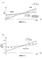
- FIG. 2 is a graph showing the relationship between the engine load and the scavenging pressure in the hull resistance reduction system according to the embodiment of the present invention.
- the hull resistance reduction system 30 discharges micro air bubbles onto the outer surface of the underwater vessel of the ship traveling above the water, particularly onto the outer surface of the bottom of the hull which is submerged below the waterline and when underwater. It is a system which reduces the frictional resistance of the hull by sailing.
- FIG. 1 shows a schematic configuration of a hull resistance reduction system 30 according to the present invention.
- the main engine 1 provided in the hull resistance reduction system 30 includes an exhaust gas system 2 (exhaust manifold), a supercharger 5, an air cooler 4 and a scavenging chamber 3.
- an exhaust turbine compressor 20 is provided separately from the supercharger 5 provided in the main engine 1.
- An exhaust bypass pipe 9 through which the exhaust gas extracted from the exhaust gas system 2 flows is connected to the exhaust turbine 20 b side of the exhaust turbine compressor 20.
- the compressor 20a, the exhaust turbine 20b, and the motor generator 21 of the exhaust turbine compressor 20 are connected by a rotating shaft 20c, and a discharge nozzle 24 extending to the surface of the hull outside the water is connected to the discharge side of the compressor 20a.
- the main engine 1 is, for example, a diesel engine for driving a main engine provided on a ship.
- the main engine 1 is driven by supplying fuel introduced from a fuel injection pump (not shown) and compressed air introduced from the turbocharger 5 into the cylinder.
- the supercharger 5 is provided between the exhaust gas system 2 of the main engine 1 and the scavenging chamber 3.
- the turbocharger 5 has a turbine 5b rotationally driven by exhaust gas led from the main engine 1, a rotating shaft 5c having one end connected to the turbine 5b, and a compressor 5a connected to the other end of the rotating shaft 5c. Is equipped.
- the rotational force obtained by the turbine 5b is transmitted through the rotation shaft 5c to be rotationally driven, and the compressor 5a compresses intake air taken in from an intake port (not shown).
- the compressed air compressed by the compressor 5 a is cooled by the air cooler 4 and then supplied to the scavenging chamber 3 of the main engine 1.
- the turbine 5 b is composed of a turbine blade that receives and rotates exhaust gas, and is housed in a turbine casing.
- the turbine casing includes a turbocharger suction pipe 6 to which the exhaust gas is led from the exhaust gas system 2 (exhaust gas manifold) of the main engine 1, and a turbocharger outlet pipe which guides the exhaust gas passing through the turbine blade to the outside of the turbine 5b. Connected to 8 and.
- the supercharger outlet pipe 8 is connected to an exhaust pipe 10 for exhausting the fuel to the outside of the ship.
- the compressor 5a has a suction pipe (not shown) connected to the suction side of the compressor 5a, and is connected to one end of a discharge pipe 7 through which compressed air flows on the discharge side of the compressor 5a. Further, an air cooler 4 is connected to the other end of the discharge pipe 7, and the air cooler 4 is connected to the scavenging chamber 3.
- An exhaust gas bypass pipe 9 is connected to the exhaust gas system 2 of the main engine 1, and the exhaust gas bypass pipe 9 is connected to an exhaust turbine 20b of an exhaust turbine compressor 20 driven by the extracted exhaust gas. Further, a control valve 11 is provided in the exhaust bypass pipe 9.
- the exhaust turbine compressor 20 has the same configuration as the turbocharger 5 except that it has a motor generator 21.
- a turbocharger outlet pipe 23 is connected to the discharge side of the exhaust turbine 20b of the exhaust turbine compressor 20. It is done.
- a discharge nozzle 24 extending to the surface of the hull outside the water is connected on the side of the compressor 20a of the exhaust turbine compressor 20, a discharge nozzle 24 extending to the surface of the hull outside the water is connected.
- the other end of the discharge nozzle 24 is provided, for example, on the surface of the ship such as the bottom of the ship, and compressed air (air that becomes air bubbles) is made into air bubbles from an opening opened to the surface of the ship Connected to a gas jet (not shown) that is jetted to the
- a gas jet not shown
- the compressor 20a, the exhaust turbine 20b and the motor generator 21 of the exhaust turbine compressor 20 are connected by a coaxial rotating shaft 20c.
- the exhaust turbine compressor 20 includes one motor generator 21 driven by the exhaust turbine compressor 20 to generate electric power.
- the exhaust turbine compressor 20 is disposed in series by connecting the motor generator 21, the compressor 20a, and the exhaust turbine 20b by the rotary shaft 20c, and the motor generator 21 is driven by the exhaust turbine compressor 20, It is generated.
- the exhaust gas extracted from the exhaust manifold 2 for collectively delivering the exhaust gas from a plurality of cylinders (not shown) to the exhaust pipe 10 is supercharged through the supercharger suction pipe 6. It is led to the 5 turbine 5b.
- the exhaust gas supplied to the turbine 5b rotationally drives the turbine 5b, and the rotational force obtained by the turbine 5b is transmitted via the rotation shaft 5c to rotationally drive the compressor 5a. This compresses the intake air.
- the compressed air compressed by the air compressor is supplied to the scavenging chamber 3 of the main engine 1 after being cooled by the air cooler 4.
- the exhaust gas supplied to the turbine 5 b is led from the turbocharger outlet piping 8 to the exhaust pipe 10 after rotating the rotating shaft 5 c.
- the exhaust gas discharged from the exhaust pipe 10 is discharged to the atmosphere from a chimney (not shown) after being subjected to necessary exhaust gas treatment.
- the exhaust turbine 20 b of the exhaust turbine compressor 20 is driven by part of the exhaust gas led via the exhaust bypass pipe 9.
- the rotational force obtained by the exhaust turbine 20 b is transmitted to the compressor 20 a and the motor generator 21 coaxial with the exhaust turbine 20 b of the exhaust turbine compressor 20.
- the compressor 20a of the exhaust turbine compressor 20 is rotationally driven and sucked by the rotational force obtained from the exhaust turbine 20b, and the air that becomes air bubbles is compressed.
- the compressor 20a is connected to a discharge nozzle 24 extending to the outer surface of the ship under water, and through the discharge nozzle 24 extended from the engine room to the bow of the ship, compressed air from an opening opened to the outer surface of the ship (Air to be air bubbles) is jetted out into the water near the outer surface of the ship as air bubbles.
- the motor generator 21 In the exhaust turbine compressor 20, the motor generator 21, the compressor 20a, and the exhaust turbine 20b are connected in series by the rotary shaft 20c.
- the motor generator 21 is inverter-controlled by the control device 22 and driven by the exhaust turbine compressor 20 to generate electric power.
- the motor generator 21 is driven by the exhaust turbine compressor 20, power of high frequency is generated, and is controlled by the control device 22 for converting it into AC power having voltage and frequency of inboard normal power. Moreover, since the motor generator 21 is inverter-controlled by the control device 22, it is, for example, variable speed drive.
- FIG. 2 (a) The relationship between the engine load and the power is shown in FIG. 2 (a).
- the engine load factor of the main engine 1 is shown on the horizontal axis, and the power is shown on the vertical axis.
- the output of the exhaust turbine 20b of the exhaust turbine compressor 20 increases.
- a point at which the line indicating the power for obtaining the necessary air and the line indicating the output of the exhaust turbine 20b intersect is, for example, 50% engine load.
- the motor generator 21 is driven by the electric power in the ship to energize the exhaust turbine compressor 20.
- the surplus output of the exhaust turbine compressor 20 is transmitted to the motor generator 21 to generate electric power.
- the relationship between the engine load and the scavenging pressure is shown in FIG.
- the required pressure is approximately 0.2 MPa (2 bar) or so, although it varies somewhat depending on the amount of air bubbled, and the horizontal axis represents the engine load factor of main engine 1, and the vertical axis represents the sweep Indicates barometric pressure.
- the discharge pressure of the compressor 20 a of the exhaust turbine compressor 20 is adjusted in order to secure the necessary pressure for compressing the lubricating air.
- the power is used by the motor generator 21 to obtain the necessary pressure using the power inside the ship.
- the control valve 11 is operated to the required pressure level and the exhaust gas supplied to the exhaust turbine 20b is adjusted to be throttled in order to pass it to the main engine 1 side. .
- the following effects are achieved.
- a part of exhaust gas extracted from the exhaust gas system 2 of the main engine 1 is used.
- the exhaust gas extracted from the exhaust gas system 2 is supplied to the exhaust turbine 20 b of the exhaust turbine compressor 20.
- the exhaust gas turbine 20b of the exhaust gas turbine compressor 20 is driven by the exhaust gas, and the air that becomes air bubbles can be stably pressurized by the compressor 20a.
- compressed air air that becomes air bubbles
- the exhaust turbine compressor 20 is preferably a hybrid supercharger in which the motor generator 21 is provided in the supercharger.
- the motor generator 21 When the pressure of the compressed air discharged from the discharge nozzle 24 falls below a predetermined value, the motor generator 21 can be operated as a motor to energize the compressor 20a. Thereby, after the energy of the exhaust gas led to the exhaust turbine compressor 20 is sufficiently recovered, the motor generator 21 can be auxiliary operated, and the consumption of the power for driving the motor generator 21 is suppressed. be able to.
- the desired compressed air pressure can be obtained only by the energy of the exhaust gas led to the exhaust turbine compressor 20, so excess exhaust can be obtained.
- the energy of the gas can be recovered by the power generation of the motor generator 21.
- the flow rate of the exhaust gas flowing into the exhaust bypass pipe 9 can be adjusted.
- the flow rate of the exhaust gas flowing in the exhaust bypass pipe 9 is throttled, and the supercharger on the main engine 1 side Supply exhaust gas to 5.
- the energy of the exhaust gas can be controlled in accordance with the state of the main engine 1, so the efficiency of the main engine 1 can be improved.
- the motor generator 21 is inverter controlled by the control device 22.
- the rotational frequency can be made variable according to the state of the main engine 1 and the like, power consumption can be further suppressed, and energy saving control can be performed.
Landscapes
- Engineering & Computer Science (AREA)
- Chemical & Material Sciences (AREA)
- Combustion & Propulsion (AREA)
- Mechanical Engineering (AREA)
- General Engineering & Computer Science (AREA)
- Physics & Mathematics (AREA)
- Fluid Mechanics (AREA)
- Ocean & Marine Engineering (AREA)
- Supercharger (AREA)
Description
本発明は、例えば汎用される船舶に用いられて好適な船体抵抗低減システムおよび船体の抵抗低減方法に関するものである。
船舶における省エネルギ技術として、船底から水中に吹き出した気泡で船体表面を覆うことで、船体に作用する摩擦抵抗を低減するということが知られている。気泡を発生させるブロワなどの送気装置を船舶に搭載し、これを別途の動力によって駆動させるというものである。この場合には、ブロワ等の駆動に要するエネルギが必要となっていた。
送気装置の駆動には燃料が必要とされるため、船舶の主機関とは別に送気装置の燃料も確保しなければならなかった。また、船舶の抵抗が低減することで削減される主推進機関の燃料よりも、送気装置の消費燃料が少なくなければならない。
これらの上述した課題の対策について開示された文献として、下記特許文献1がある。
特許文献1には、船舶の水中の船体外表面に気泡を放出して航行時の摩擦抵抗を低減する船体抵抗低減装置が示されている。当該船体抵抗低減装置は、船舶の主機関からの排気ガスによって駆動され、また、主機関に燃焼用空気を圧送する過給機を備えており、過給機から主機関へ供給される燃焼用空気を抽気して船体外表面に放出するとともに、過給機には排気流速を2段階に調整可能な可変ノズルが備えられ、燃焼用空気を抽気して船体外表面に放出する場合は可変ノズルを絞り、燃焼用空気を抽気して船体外表面に放出しない場合は可変ノズルを開くことが示されている。
これにより、気泡放出にエネルギを消費する駆動源が不要になるので、余分な動力を消費することなく気泡を放出できる省エネルギ効果の高い船体抵抗低減装置が示されている。また、過給機は、排気流速を2段階に調整可能な可変ノズルを備えているので、可変ノズルの2段階切替によるシンプルな制御が可能となることが示されている。さらに、過給機に2段階に調整可能な可変ノズル付過給機を採用して気泡停止時高負荷運転モードを設けると、気泡を放出しない高負荷運転領域でも燃焼用空気圧力の上昇を抑制する無駄な抽気が不要になり、主機関の効率改善が可能になることが示されている。
特許文献1には、ディーゼル主機関の掃気の一部を船底に導くことが記載されている。しかし、掃気の圧力は機関負荷によって変化するが、気泡放出に必要な空気の圧力と空気量は略一定である。したがって、低負荷では圧力、空気量が不足し、高負荷では気泡となる空気を減圧しなければならない必要があるという恐れがある。
また、主機関の掃気を用いている場合には、低負荷運転時に圧力や空気量が減少するのを補う補助的な圧縮機を用いている。これにより、コストや燃料にかけるコストが多くなる。また、補助圧縮機と掃気のバランスの制御が困難である。
また、掃気圧が必要な気泡放出用空気圧力より高い場合は、減圧弁で圧力を調整する必要がある。これにより、系全体ではエネルギの損失となる。
本発明は、このような事情に鑑みてなされたものであって、排気ガスのエネルギを用いて気泡となる空気を圧縮し、水中の船体外表面へと安定して供給することができる船体抵抗低減システムおよび船体の抵抗低減方法を提供することを目的とする。
上記課題を解決するために、本発明の船体抵抗低減システムおよび船体の抵抗低減方法は以下の手段を採用する。
本発明の第1の態様に係る船体抵抗低減システムは、主機関と、前記主機関の排気ガスの一部が導かれて動作する排気タービン圧縮機と、該排気タービン圧縮機から導かれた圧縮空気を船舶の船体外表面へと導くための吐出ノズルと、を備え、前記排気タービン圧縮機は、導かれた排気ガスによって回転駆動される排気タービンと、該排気タービンの回転駆動力を得て空気を圧縮するコンプレッサと、前記排気タービンによる発電および前記コンプレッサの加勢を行う電動発電機と、を備えている。
本発明の第1の態様に係る船体抵抗低減システムは、主機関と、前記主機関の排気ガスの一部が導かれて動作する排気タービン圧縮機と、該排気タービン圧縮機から導かれた圧縮空気を船舶の船体外表面へと導くための吐出ノズルと、を備え、前記排気タービン圧縮機は、導かれた排気ガスによって回転駆動される排気タービンと、該排気タービンの回転駆動力を得て空気を圧縮するコンプレッサと、前記排気タービンによる発電および前記コンプレッサの加勢を行う電動発電機と、を備えている。
この第1の態様では、主機関に用いられる過給機とは別に、船体抵抗を低減させる気泡となる空気を圧縮するための排気タービン圧縮機が設けられる。この過給機の動力源は、主機関の排気ガス系統(例えば、排気ガスマニフォールド)から抽気した一部の排気ガスが用いられる。排気ガス系統から抽気された排気ガスは、過給機の排気タービンへと供給される。これにより、排気ガスのエネルギの一部を空気の圧縮に利用する排熱回収の効果によって、気泡となる空気を圧縮するために必要な動力を削減することができる。排気ガスにより過給機の排気タービンを駆動して安定してコンプレッサにより気泡となる空気を昇圧することができる。これにより、船体外表面に安定して圧縮空気(気泡となる空気)を供給することができるので、船体と海水との摩擦を安定して低減することができる。
なお、排気タービン圧縮機としては、過給機に電動発電機が設けられたハイブリッド過給機が好適に用いられる。
なお、排気タービン圧縮機としては、過給機に電動発電機が設けられたハイブリッド過給機が好適に用いられる。
本発明の第2の態様に係る船体抵抗低減システムは、前記吐出ノズルから吐出される圧縮空気の圧力が所定値を下回った場合に、前記電動発電機により前記コンプレッサの加勢を行う。
この第2の態様では、吐出ノズルから吐出される圧縮空気の圧力が所定値を下回る場合には、電動発電機を電動機として動作させてコンプレッサを加勢することができる。これにより、排気タービン圧縮機に導かれた排気ガスのエネルギを十分に回収したうえで、電動発電機を補助的に稼働することができ、電動発電機を駆動させる電力の消費を抑えることができる。
本発明の第3の態様に係る船体抵抗低減システムは、吐出ノズルから吐出される圧縮空気の圧力が所定値を上回る場合には、前記電動発電機を発電機として動作させて電力を船内に供給する。
この第3の態様では、吐出ノズルから吐出される圧縮空気の圧力が所定値を上回る場合には、排気タービン圧縮機に導かれた排気ガスのエネルギのみで所望の圧縮空気圧力が得られるので、余剰の排気ガスのエネルギを電動発電機の発電にて回収させることができる。このように発電した電力を船内に供給することで、船内の需要電力を賄うために必要な燃料の消費を抑えることができる。
本発明の第4の態様に係る船体抵抗低減システムは、前記主機関の排気ガスの一部を前記排気タービン圧縮機に導く前記排気バイパス管に制御弁が設けられている。
この第4の態様では、排気バイパス管に制御弁を設けることにより、排気バイパス管内に流れる排気ガスの流量を調整することができる。これにより、主機関の負荷が所定値を上回る状態で電動発電機による発電が行われている場合は、排気バイパス管内を流れる排気ガスの流量を絞り主機関側の過給機へと排気ガスを供給する。これにより、排気ガスのエネルギを主機関の状態に合わせて制御することができるので、主機関の効率を向上させることができる。
本発明の第5の態様に係る船体抵抗低減システムは、前記電動発電機はインバータ制御により可変速駆動とされる。
この第5の態様では、電動発電機はインバータ制御とされている。これにより、主機関の状態等に応じて回転周波数を可変とすることができ、さらに電力の消費を抑えることができる省エネ制御とすることができる。
本発明の第6の態様に係る船体の抵抗低減方法は、主機関の排気ガスの一部を導入することで排気タービン圧縮機を駆動する工程と、該排気タービンの駆動によりコンプレッサを駆動させることで空気を圧縮する工程と、該圧縮した空気を吐出ノズルにより水中の船体外表面へと導く工程と、を備えた船体の抵抗低減方法であって、前記吐出ノズルから吐出される空気の圧力が所定値を下回った場合に、電動発電機により前記コンプレッサの加勢を行う工程をさらに備えている。
本発明の第7の態様に係る船体の抵抗低減方法は、主機関の排気ガスの一部を導入することで排気タービン圧縮機を駆動する工程と、該排気タービンの駆動によりコンプレッサを駆動させることで空気を圧縮する工程と、該圧縮した空気を吐出ノズルにより水中の船体外表面へと導く工程と、を備えた船体の抵抗低減方法であって、前記吐出ノズルから吐出される空気の圧力が所定値を上回る場合には、電動発電機を発電機として動作させて電力を船内に供給する工程をさらに備えている。
これらの船体の抵抗低減方法を用いることにより、排気ガスのエネルギの一部を空気の圧縮に利用する排熱回収の効果によって、気泡となる空気を圧縮するために必要な動力を削減することができる。
本発明では、気泡となる空気を圧縮するための排気タービン圧縮機を設けることとした。この排気タービン圧縮機の動力源は、主機関の排気ガス系統から抽気した一部の排気ガスが用いられる。これにより、排気ガスのエネルギの一部を空気の圧縮に利用する排熱回収の効果によって、気泡となる空気を圧縮するために必要な動力を削減することができる。排気ガスにより排気タービン圧縮機のタービンを駆動して安定してコンプレッサによる気泡となる空気を昇圧することができる。これにより、水中の船体外表面に安定して圧縮空気(気泡となる空気)を供給することができるので、船体と海水との摩擦を安定して低減することができる。
以下に、本発明に係る船体抵抗低減システムおよび船体の抵抗低減方法の一実施形態について、図1及び図2を参照して説明する。
船体抵抗低減システム30は、水上を航行する船舶の水中の船体外表面上に対し、特に、喫水線より下で航行時に水中となる船体の船底部外表面上に対し、微小な気泡を放出しながら航行することにより船体の摩擦抵抗を低減するシステムである。
船体抵抗低減システム30は、水上を航行する船舶の水中の船体外表面上に対し、特に、喫水線より下で航行時に水中となる船体の船底部外表面上に対し、微小な気泡を放出しながら航行することにより船体の摩擦抵抗を低減するシステムである。
図1には、本発明に係る船体抵抗低減システム30の概略構成が示されている。
船体抵抗低減システム30に設けられた主機関1は、排気ガス系統2(排気マニフォールド)と、過給機5とエアクーラ4及び掃気室3から構成される。
船体抵抗低減システム30に設けられた主機関1は、排気ガス系統2(排気マニフォールド)と、過給機5とエアクーラ4及び掃気室3から構成される。
また、主機関1に設けられた過給機5とは別に排気タービン圧縮機20が設けられている。排気ガス系統2から抽気した排気ガスが流れる排気バイパス管9が排気タービン圧縮機20の排気タービン20b側に接続される。また、排気タービン圧縮機20のコンプレッサ20a、排気タービン20b及び電動発電機21は、回転軸20cで連結され、コンプレッサ20aの吐出側には、水中の船体外表面へと延在する吐出ノズル24が接続される。
主機関1は、例えば、船舶に設けられた主機駆動用のディーゼルエンジンとされている。主機関1は、図示しない燃料噴射ポンプから導かれた燃料と、過給機5から導かれた圧縮空気とが筒内に供給されることによって駆動される。
過給機5は、主機関1の排気ガス系統2と掃気室3の間に設けられる。過給機5は、主機関1から導かれた排気ガスにより回転駆動されるタービン5bと、一端にタービン5bが接続された回転軸5cと、回転軸5cの他端に接続されたコンプレッサ5aとを備えている。このコンプレッサ5aは、タービン5bによって得られた回転力が回転軸5cを介して伝達されて回転駆動させられるようになっており、これにより図示されない吸入口から吸入された吸入空気を圧縮する。コンプレッサ5aによって圧縮された圧縮空気は、エアクーラ4にて冷却された後に、主機関1の掃気室3へと供給される。
タービン5bは、排気ガスを受けて回転するタービン翼から構成されており、タービンケーシング内に収容されている。タービンケーシングは、主機関1の排気ガス系統2(排ガスマニフォールド)から排気ガスが導かれる過給機吸入配管6と、タービン翼を通過した排気ガスをタービン5bの外へと導く過給機出口配管8とに対して接続されている。過給機出口配管8は、船体外へと排気するための排気管10に接続されている。
コンプレッサ5aは、図示しない吸入配管がコンプレッサ5aの吸入側に接続され、コンプレッサ5aの吐出側には、圧縮空気が流れる吐出配管7の一端に接続されている。また、吐出配管7の他端には、エアクーラ4が接続され、エアクーラ4は掃気室3に接続されている。
主機関1の排気ガス系統2には排気バイパス管9が接続され、排気バイパス管9は抽気された排気ガスにより駆動される排気タービン圧縮機20の排気タービン20bへと接続されている。また、排気バイパス管9には、制御弁11が設けられる。排気タービン圧縮機20は、電動発電機21を有する点を除き過給機5と同様の構成とされ、排気タービン圧縮機20の排気タービン20bの吐出側には、過給機出口配管23が接続されている。
排気タービン圧縮機20のコンプレッサ20a側には、水中の船体外表面に延在する吐出ノズル24が接続されている。また、吐出ノズル24の他方の端部には、例えば、船底等の船体外表面に備えられ、船体外表面に開いた開口から圧縮空気(気泡となる空気)を気泡として船体外表面付近の水中に噴出する気体噴出口(図示せず)が接続される。例えば、排気タービン圧縮機20は機関室に設けられているので、吐出ノズル24は、船舶の船首まで伸ばされて用いられる。
また、排気タービン圧縮機20のコンプレッサ20a、排気タービン20b及び電動発電機21は、同軸とされた回転軸20cにより連結される。排気タービン圧縮機20は、排気タービン圧縮機20により駆動されて発電する1台の電動発電機21を備えている。そして、排気タービン圧縮機20は、電動発電機21、コンプレッサ20a及び排気タービン20b間を回転軸20cにより接続することで直列に配置され、電動発電機21は、排気タービン圧縮機20により駆動され、発電される。
次に上記構成の船体抵抗低減システムの動作について説明する。
主機関1において、複数の気筒(図示せず)からの排気ガスをまとめて排気管10に渡すための排気マニフォールド2から抽気された排気ガスが、過給機吸入配管6を介して過給機5のタービン5bへと導かれる。タービン5bに供給された排気ガスによりタービン5bを回転駆動させて、タービン5bによって得られた回転力が回転軸5cを介して伝達されてコンプレッサ5aを回転駆動させる。これにより吸入空気を圧縮する。空気圧縮機によって圧縮された圧縮空気は、エアクーラ4にて冷却された後に、主機関1の掃気室3へと供給される。タービン5bへと供給された排気ガスは、回転軸5cを回転させた後に、過給機出口配管8から排気管10へと導かれる。なお、排気管10から排出される排気ガスは、必要な排ガス処理を施した後、煙突(図示せず)から大気に放出される。
主機関1において、複数の気筒(図示せず)からの排気ガスをまとめて排気管10に渡すための排気マニフォールド2から抽気された排気ガスが、過給機吸入配管6を介して過給機5のタービン5bへと導かれる。タービン5bに供給された排気ガスによりタービン5bを回転駆動させて、タービン5bによって得られた回転力が回転軸5cを介して伝達されてコンプレッサ5aを回転駆動させる。これにより吸入空気を圧縮する。空気圧縮機によって圧縮された圧縮空気は、エアクーラ4にて冷却された後に、主機関1の掃気室3へと供給される。タービン5bへと供給された排気ガスは、回転軸5cを回転させた後に、過給機出口配管8から排気管10へと導かれる。なお、排気管10から排出される排気ガスは、必要な排ガス処理を施した後、煙突(図示せず)から大気に放出される。
一方、排気タービン圧縮機20の排気タービン20bは、排気バイパス管9を介して導かれた一部の排気ガスにより駆動される。排気タービン20bにより得られた回転力は、排気タービン圧縮機20の排気タービン20bと同軸とされるコンプレッサ20a及び電動発電機21へと伝達される。
排気タービン圧縮機20のコンプレッサ20aは、排気タービン20bから得られる回転力で回転駆動されて吸入されそして気泡となる空気が圧縮される。また、コンプレッサ20aには、水中の船体外表面に延在する吐出ノズル24が接続され、機関室から船舶の船首まで伸ばされた吐出ノズル24を介し、船体外表面に開いた開口部から圧縮空気(気泡となる空気)が気泡として船体外表面付近の水中に噴出される。
排気タービン圧縮機20では、電動発電機21、コンプレッサ20a,排気タービン20bが回転軸20cにより接続することで直列に配置されている。電動発電機21は、制御装置22によりインバータ制御されるとともに、排気タービン圧縮機20により駆動されて発電される。
さらに、電動発電機21は、排気タービン圧縮機20により駆動され、周波数の高い電力が発電され、船内常用電力の電圧及び周波数を有する交流電源に変換するための制御装置22により制御される。また、電動発電機21は、制御装置22によりインバータ制御されるため、例えば、可変速駆動とされる。
図2(a)には、機関負荷と動力との関係が示される。主機関1の機関負荷率を横軸に示し、縦軸に動力を示す。
主機関1の機関負荷が上昇すると、排気タービン圧縮機20の排気タービン20bの出力が上昇する。必要な空気を得る為の動力を示す線と、排気タービン20bの出力を示す線が交差する箇所を、例えば機関負荷50%とする。この場合、機関負荷50%以下の時に電動発電機21を船内の電力で駆動させて、排気タービン圧縮機20を加勢する。また、機関負荷50%以上の時は、余剰となった排気タービン圧縮機20の出力が電動発電機21へと伝達させて発電される。
主機関1の機関負荷が上昇すると、排気タービン圧縮機20の排気タービン20bの出力が上昇する。必要な空気を得る為の動力を示す線と、排気タービン20bの出力を示す線が交差する箇所を、例えば機関負荷50%とする。この場合、機関負荷50%以下の時に電動発電機21を船内の電力で駆動させて、排気タービン圧縮機20を加勢する。また、機関負荷50%以上の時は、余剰となった排気タービン圧縮機20の出力が電動発電機21へと伝達させて発電される。
図2(b)には、機関負荷と掃気圧との関係が示されている。必要な圧力は、気泡となる空気の必要量により多少の変化はあるが、ほぼ一定の0.2MPa(2bar)程度であり、主機関1の機関負荷率を横軸に示し、縦軸に掃気圧を示す。
潤滑空気を圧縮する必要な圧力を確保するため、排気タービン圧縮機20のコンプレッサ20aの吐出圧が調整される。機関負荷が50%よりも低い場合は、船内の電力を用いて電動発電機21により、必要な圧力となるように加勢される。また、吐出圧が余剰となる場合は、例えば、必要な圧力程度まで制御弁11を操作して排気タービン20bへと供給される排気ガスを主機関1側にまわすために絞るように調整される。
潤滑空気を圧縮する必要な圧力を確保するため、排気タービン圧縮機20のコンプレッサ20aの吐出圧が調整される。機関負荷が50%よりも低い場合は、船内の電力を用いて電動発電機21により、必要な圧力となるように加勢される。また、吐出圧が余剰となる場合は、例えば、必要な圧力程度まで制御弁11を操作して排気タービン20bへと供給される排気ガスを主機関1側にまわすために絞るように調整される。
本実施形態によれば、以下の作用効果を奏する。
排気タービン圧縮機20の動力源は、主機関1の排気ガス系統2から抽気した一部の排気ガスが用いられる。排気ガス系統2から抽気された排気ガスは、排気タービン圧縮機20の排気タービン20bへと供給される。これにより、排気ガスのエネルギの一部を空気の圧縮に利用する排熱回収の効果によって、気泡となる空気を圧縮するために必要な動力を削減することができる。
排気タービン圧縮機20の動力源は、主機関1の排気ガス系統2から抽気した一部の排気ガスが用いられる。排気ガス系統2から抽気された排気ガスは、排気タービン圧縮機20の排気タービン20bへと供給される。これにより、排気ガスのエネルギの一部を空気の圧縮に利用する排熱回収の効果によって、気泡となる空気を圧縮するために必要な動力を削減することができる。
また、排気ガスにより排気タービン圧縮機20の排気タービン20bを駆動して、安定してコンプレッサ20aにより、気泡となる空気を昇圧することができる。これにより、水中の船体外表面に安定して圧縮空気(気泡となる空気)を供給することができるので、船体と海水との摩擦を安定して低減することができる。
なお、排気タービン圧縮機20としては、過給機に電動発電機21が設けられたハイブリッド過給機とすることが好ましい。
なお、排気タービン圧縮機20としては、過給機に電動発電機21が設けられたハイブリッド過給機とすることが好ましい。
吐出ノズル24から吐出される圧縮空気の圧力が所定値を下回る場合には、電動発電機21を電動機として動作させてコンプレッサ20aを加勢することができる。これにより、排気タービン圧縮機20に導かれた排気ガスのエネルギを十分に回収したうえで、電動発電機21を補助的に稼働することができ、電動発電機21を駆動させる電力の消費を抑えることができる。
また、吐出ノズル24から吐出される圧縮空気の圧力が所定値を上回る場合には、排気タービン圧縮機20に導かれた排気ガスのエネルギのみで所望の圧縮空気圧力が得られるので、余剰の排気ガスのエネルギを電動発電機21の発電にて回収させることができる。このように発電した電力を船内に供給することで、船内の需要電力を賄うために必要な燃料の消費を抑えることができる。さらに、吐出ノズル24は、機関室から船舶の船首まで延存して設けられるので、機関から船首までの間に圧縮空気を自然冷却することができる。これにより、圧縮空気を冷却するエアクーラ4を設ける必要がなく、コストを削減することができる。
排気バイパス管9に制御弁11を設けることにより、排気バイパス管9内に流れる排気ガスの流量を調整することができる。これにより、主機関1の負荷が所定値を上回る状態で電動発電機21による発電が行われている場合は、排気バイパス管9内を流れる排気ガスの流量を絞り主機関1側の過給機5へと排気ガスを供給する。これにより、排気ガスのエネルギを主機関1の状態に合わせて制御することができるので、主機関1の効率を向上させることができる。
電動発電機21が制御装置22によりインバータ制御されることとした。これにより、主機関1の状態等に応じて回転周波数を可変とすることができ、さらに電力の消費を抑えることができ、省エネ制御とすることができる。
1 主機関
2 排気系統(排気マニフォールド)
3 掃気室
4 エアクーラ
5 過給機
5a コンプレッサ
5b タービン
5c 回転軸
6 過給機吸入配管
7 吐出配管
8 過給機出口配管
9 排気バイパス管
10 排気管
11 制御弁
20 排気タービン圧縮機
20a コンプレッサ
20b 排気タービン
20c 回転軸
21 電動発電機
22 制御装置
23 過給機出口配管
24 吐出ノズル
2 排気系統(排気マニフォールド)
3 掃気室
4 エアクーラ
5 過給機
5a コンプレッサ
5b タービン
5c 回転軸
6 過給機吸入配管
7 吐出配管
8 過給機出口配管
9 排気バイパス管
10 排気管
11 制御弁
20 排気タービン圧縮機
20a コンプレッサ
20b 排気タービン
20c 回転軸
21 電動発電機
22 制御装置
23 過給機出口配管
24 吐出ノズル
Claims (7)
- 主機関と、
前記主機関の排気ガスの一部が導かれて動作する排気タービン圧縮機と、
該排気タービン圧縮機から導かれた圧縮空気を船舶の水中の船体外表面へと導くための吐出ノズルと、
を備え、
前記排気タービン圧縮機は、前記導かれた排気ガスによって回転駆動される排気タービンと、該排気タービンの回転駆動力を得て空気を圧縮するコンプレッサと、前記排気タービンによる発電および前記コンプレッサの加勢を行う電動発電機と、を備えている船体抵抗低減システム。 - 前記吐出ノズルから吐出される圧縮空気の圧力が所定値を下回った場合に、前記電動発電機により前記コンプレッサの加勢を行う請求項1に記載の船体抵抗低減システム。
- 吐出ノズルから吐出される圧縮空気の圧力が所定値を上回る場合には、前記電動発電機を発電機として動作させて電力を船内に供給する請求項1または2に記載の船体抵抗低減システム。
- 前記主機関の排気ガスの一部を前記排気タービン圧縮機に導く前記排気バイパス管には制御弁が設けられている請求項1から3のいずれかに記載の船体抵抗低減システム。
- 前記電動発電機はインバータ制御により可変速駆動とされる請求項1から4のいずれかに記載の船体抵抗低減システム。
- 主機関の排気ガスの一部を導入することで排気タービン圧縮機を駆動する工程と、
該排気タービンの駆動によりコンプレッサを駆動させることで空気を圧縮する工程と、
該圧縮した空気を吐出ノズルにより水中の船体外表面へと導く工程と、を備えた船体の抵抗低減方法であって、
前記吐出ノズルから吐出される空気の圧力が所定値を下回った場合に、電動発電機により前記コンプレッサの加勢を行う工程、
をさらに備えている船体の抵抗低減方法。 - 主機関の排気ガスの一部を導入することで排気タービン圧縮機を駆動する工程と、
該排気タービンの駆動によりコンプレッサを駆動させることで空気を圧縮する工程と、
該圧縮した空気を吐出ノズルにより水中の船体外表面へと導く工程と、を備えた船体の抵抗低減方法であって、
前記吐出ノズルから吐出される空気の圧力が所定値を上回る場合には、電動発電機を発電機として動作させて電力を船内に供給する工程、
を備えている船体の抵抗低減方法。
Priority Applications (2)
| Application Number | Priority Date | Filing Date | Title |
|---|---|---|---|
| CN201380046848.1A CN104755368B (zh) | 2012-10-12 | 2013-10-10 | 船体减阻系统及船体的减阻方法 |
| KR1020157006167A KR101599681B1 (ko) | 2012-10-12 | 2013-10-10 | 선체저항저감 시스템 및 선체의 저항저감 방법 |
Applications Claiming Priority (2)
| Application Number | Priority Date | Filing Date | Title |
|---|---|---|---|
| JP2012226888A JP5805044B2 (ja) | 2012-10-12 | 2012-10-12 | 船体抵抗低減システムおよび船体の抵抗低減方法 |
| JP2012-226888 | 2012-10-12 |
Publications (1)
| Publication Number | Publication Date |
|---|---|
| WO2014058008A1 true WO2014058008A1 (ja) | 2014-04-17 |
Family
ID=50477474
Family Applications (1)
| Application Number | Title | Priority Date | Filing Date |
|---|---|---|---|
| PCT/JP2013/077583 Ceased WO2014058008A1 (ja) | 2012-10-12 | 2013-10-10 | 船体抵抗低減システムおよび船体の抵抗低減方法 |
Country Status (4)
| Country | Link |
|---|---|
| JP (1) | JP5805044B2 (ja) |
| KR (1) | KR101599681B1 (ja) |
| CN (1) | CN104755368B (ja) |
| WO (1) | WO2014058008A1 (ja) |
Cited By (4)
| Publication number | Priority date | Publication date | Assignee | Title |
|---|---|---|---|---|
| WO2018142805A1 (ja) * | 2017-01-31 | 2018-08-09 | 三菱重工業株式会社 | 船舶の摩擦低減装置 |
| US10985608B2 (en) | 2016-12-13 | 2021-04-20 | General Electric Company | Back-up power system for a component and method of assembling same |
| EP3895973A1 (en) * | 2020-04-14 | 2021-10-20 | ABB Schweiz AG | Air supply apparatus for a ship, ship including the same, and method of supplying air to an air lubrication device |
| EP3933180A1 (de) * | 2020-07-01 | 2022-01-05 | MAN Energy Solutions SE | Schiffsantriebssystem und verfahren zum betreiben desselben |
Families Citing this family (6)
| Publication number | Priority date | Publication date | Assignee | Title |
|---|---|---|---|---|
| KR102109422B1 (ko) * | 2014-05-08 | 2020-05-12 | 현대자동차 주식회사 | 3단 터보 차저 시스템 및 그 제어방법 |
| JP6555724B2 (ja) * | 2014-06-27 | 2019-08-07 | 国立研究開発法人 海上・港湾・航空技術研究所 | 空気潤滑式船舶の空気供給制御システム及び空気潤滑式船舶 |
| JP6647630B2 (ja) * | 2014-07-11 | 2020-02-14 | 国立研究開発法人 海上・港湾・航空技術研究所 | 空気潤滑式船舶の空気供給システム |
| KR101629363B1 (ko) * | 2015-01-07 | 2016-06-10 | 대우조선해양 주식회사 | 폐열회수를 이용한 전력생산 시스템 |
| WO2020192932A1 (en) * | 2019-03-28 | 2020-10-01 | Abb Schweiz Ag | Air supply apparatus for a ship, ship including the same, and method fof supplying air to an air lubrication device |
| KR102652786B1 (ko) * | 2019-08-30 | 2024-03-29 | 삼성중공업 주식회사 | 선박의 공기윤활시스템 |
Citations (5)
| Publication number | Priority date | Publication date | Assignee | Title |
|---|---|---|---|---|
| JPH11348871A (ja) * | 1998-06-12 | 1999-12-21 | Ishikawajima Harima Heavy Ind Co Ltd | マイクロバブル装置への空気供給量制御方法 |
| JP2010023631A (ja) * | 2008-07-17 | 2010-02-04 | National Maritime Research Institute | 船舶の噴出気体供給方法及び噴出気体制御装置 |
| JP2010274905A (ja) * | 2009-05-26 | 2010-12-09 | Man Diesel Se | 船舶推進システム及び該システムを装備する船舶 |
| JP2011149327A (ja) * | 2010-01-21 | 2011-08-04 | Mitsubishi Heavy Ind Ltd | エンジン排気エネルギー回収装置、これを備える船舶およびこれを備える発電プラント |
| JP2012171582A (ja) * | 2011-02-24 | 2012-09-10 | Mitsubishi Heavy Ind Ltd | 船体抵抗低減装置 |
Family Cites Families (7)
| Publication number | Priority date | Publication date | Assignee | Title |
|---|---|---|---|---|
| DE3711863A1 (de) * | 1987-04-08 | 1988-10-27 | Man B & W Diesel Gmbh | Mehrmotorenanlage fuer schiffe |
| JPH11348870A (ja) * | 1998-06-12 | 1999-12-21 | Ishikawajima Harima Heavy Ind Co Ltd | マイクロバブル装置への過給機からの空気供給装置 |
| JP3605639B2 (ja) * | 2001-12-13 | 2004-12-22 | 独立行政法人海上技術安全研究所 | ガスタービン発電式電気推進船 |
| JP3682531B2 (ja) * | 2002-03-05 | 2005-08-10 | 独立行政法人海上技術安全研究所 | ハイブリッド型舶用推進装置 |
| DK2367717T3 (da) * | 2008-12-02 | 2013-12-16 | Dk Group Acs B V | Overtryksmikroboblegenerator |
| JP2013129406A (ja) * | 2011-12-22 | 2013-07-04 | Mitsubishi Heavy Ind Ltd | 船舶の空気潤滑システム |
| JP5294135B1 (ja) * | 2012-03-22 | 2013-09-18 | 西芝電機株式会社 | 船舶の圧縮空気供給システムとその装置 |
-
2012
- 2012-10-12 JP JP2012226888A patent/JP5805044B2/ja not_active Expired - Fee Related
-
2013
- 2013-10-10 WO PCT/JP2013/077583 patent/WO2014058008A1/ja not_active Ceased
- 2013-10-10 KR KR1020157006167A patent/KR101599681B1/ko not_active Expired - Fee Related
- 2013-10-10 CN CN201380046848.1A patent/CN104755368B/zh not_active Expired - Fee Related
Patent Citations (5)
| Publication number | Priority date | Publication date | Assignee | Title |
|---|---|---|---|---|
| JPH11348871A (ja) * | 1998-06-12 | 1999-12-21 | Ishikawajima Harima Heavy Ind Co Ltd | マイクロバブル装置への空気供給量制御方法 |
| JP2010023631A (ja) * | 2008-07-17 | 2010-02-04 | National Maritime Research Institute | 船舶の噴出気体供給方法及び噴出気体制御装置 |
| JP2010274905A (ja) * | 2009-05-26 | 2010-12-09 | Man Diesel Se | 船舶推進システム及び該システムを装備する船舶 |
| JP2011149327A (ja) * | 2010-01-21 | 2011-08-04 | Mitsubishi Heavy Ind Ltd | エンジン排気エネルギー回収装置、これを備える船舶およびこれを備える発電プラント |
| JP2012171582A (ja) * | 2011-02-24 | 2012-09-10 | Mitsubishi Heavy Ind Ltd | 船体抵抗低減装置 |
Cited By (6)
| Publication number | Priority date | Publication date | Assignee | Title |
|---|---|---|---|---|
| US10985608B2 (en) | 2016-12-13 | 2021-04-20 | General Electric Company | Back-up power system for a component and method of assembling same |
| WO2018142805A1 (ja) * | 2017-01-31 | 2018-08-09 | 三菱重工業株式会社 | 船舶の摩擦低減装置 |
| EP3895973A1 (en) * | 2020-04-14 | 2021-10-20 | ABB Schweiz AG | Air supply apparatus for a ship, ship including the same, and method of supplying air to an air lubrication device |
| WO2021209422A1 (en) * | 2020-04-14 | 2021-10-21 | Abb Switzerland Ltd. | Air supply apparatus for a ship, ship including the same, and method for supplying air to an air lubrication device |
| US12263913B2 (en) | 2020-04-14 | 2025-04-01 | Accelleron Switzerland Ltd. | Air supply apparatus for a ship, ship including the same, and method for supplying air to an air lubrication device |
| EP3933180A1 (de) * | 2020-07-01 | 2022-01-05 | MAN Energy Solutions SE | Schiffsantriebssystem und verfahren zum betreiben desselben |
Also Published As
| Publication number | Publication date |
|---|---|
| KR20150041129A (ko) | 2015-04-15 |
| KR101599681B1 (ko) | 2016-03-03 |
| JP2014076783A (ja) | 2014-05-01 |
| CN104755368A (zh) | 2015-07-01 |
| JP5805044B2 (ja) | 2015-11-04 |
| CN104755368B (zh) | 2016-07-20 |
Similar Documents
| Publication | Publication Date | Title |
|---|---|---|
| WO2014058008A1 (ja) | 船体抵抗低減システムおよび船体の抵抗低減方法 | |
| KR102359459B1 (ko) | 공기 윤활식 선박의 공기 공급 시스템 | |
| JP5808128B2 (ja) | ガス焚きエンジン | |
| CN101896706B (zh) | 增压装置 | |
| CN106458290B (zh) | 空气润滑式船舶的空气供给控制系统以及空气润滑式船舶 | |
| JP5294135B1 (ja) | 船舶の圧縮空気供給システムとその装置 | |
| KR102660673B1 (ko) | 배를 위한 공기 공급 장치, 이를 포함하는 배, 및 공기를 공기 윤활 디바이스에 공급하기 위한 방법 | |
| JP2011089488A (ja) | ターボコンパウンドシステムおよびその運転方法 | |
| WO2012114840A1 (ja) | 船体抵抗低減装置 | |
| CN101858240A (zh) | 具有废气洗涤器的大型二冲程柴油发动机 | |
| CN101898548A (zh) | 船驱动系统以及装备着该船驱动系统的船 | |
| CN107532502B (zh) | 内燃机的增压器剩余动力回收装置 | |
| JP6364691B2 (ja) | 内燃機関の過給機余剰動力回収装置 | |
| JP2008111384A (ja) | 船舶用エンジンの余剰排気エネルギ回収システム | |
| CN104302544B (zh) | 原动机系统及具备该原动机系统的船舶 | |
| JP5908056B2 (ja) | ガス焚きエンジン | |
| KR102694835B1 (ko) | 선박 엔진의 소기를 이용한 기포 배출시스템 및 방법 | |
| JP6348637B1 (ja) | 内燃機関の過給機余剰動力回収装置及び船舶 | |
| WO2025093440A1 (en) | Air supply apparatus, ship including the same, and method of supplying air to an air-powered device | |
| CN109874332B (zh) | 内燃机的增压器剩余动力回收装置及船舶 | |
| JP2003049674A (ja) | 内燃機関用過給システム | |
| JP2015166596A (ja) | ガス焚きエンジン |
Legal Events
| Date | Code | Title | Description |
|---|---|---|---|
| 121 | Ep: the epo has been informed by wipo that ep was designated in this application |
Ref document number: 13845288 Country of ref document: EP Kind code of ref document: A1 |
|
| ENP | Entry into the national phase |
Ref document number: 20157006167 Country of ref document: KR Kind code of ref document: A |
|
| NENP | Non-entry into the national phase |
Ref country code: DE |
|
| 122 | Ep: pct application non-entry in european phase |
Ref document number: 13845288 Country of ref document: EP Kind code of ref document: A1 |