WO2014058005A1 - 入力装置及び前記入力装置を用いた複数点の荷重検出方法 - Google Patents
入力装置及び前記入力装置を用いた複数点の荷重検出方法 Download PDFInfo
- Publication number
- WO2014058005A1 WO2014058005A1 PCT/JP2013/077563 JP2013077563W WO2014058005A1 WO 2014058005 A1 WO2014058005 A1 WO 2014058005A1 JP 2013077563 W JP2013077563 W JP 2013077563W WO 2014058005 A1 WO2014058005 A1 WO 2014058005A1
- Authority
- WO
- WIPO (PCT)
- Prior art keywords
- pressing
- load
- point
- sensitivity
- sensor
- Prior art date
- Legal status (The legal status is an assumption and is not a legal conclusion. Google has not performed a legal analysis and makes no representation as to the accuracy of the status listed.)
- Ceased
Links
Images



Classifications
-
- G—PHYSICS
- G06—COMPUTING OR CALCULATING; COUNTING
- G06F—ELECTRIC DIGITAL DATA PROCESSING
- G06F3/00—Input arrangements for transferring data to be processed into a form capable of being handled by the computer; Output arrangements for transferring data from processing unit to output unit, e.g. interface arrangements
- G06F3/01—Input arrangements or combined input and output arrangements for interaction between user and computer
- G06F3/03—Arrangements for converting the position or the displacement of a member into a coded form
- G06F3/041—Digitisers, e.g. for touch screens or touch pads, characterised by the transducing means
- G06F3/044—Digitisers, e.g. for touch screens or touch pads, characterised by the transducing means by capacitive means
- G06F3/0447—Position sensing using the local deformation of sensor cells
-
- G—PHYSICS
- G06—COMPUTING OR CALCULATING; COUNTING
- G06F—ELECTRIC DIGITAL DATA PROCESSING
- G06F3/00—Input arrangements for transferring data to be processed into a form capable of being handled by the computer; Output arrangements for transferring data from processing unit to output unit, e.g. interface arrangements
- G06F3/01—Input arrangements or combined input and output arrangements for interaction between user and computer
- G06F3/03—Arrangements for converting the position or the displacement of a member into a coded form
- G06F3/041—Digitisers, e.g. for touch screens or touch pads, characterised by the transducing means
- G06F3/0414—Digitisers, e.g. for touch screens or touch pads, characterised by the transducing means using force sensing means to determine a position
-
- G—PHYSICS
- G06—COMPUTING OR CALCULATING; COUNTING
- G06F—ELECTRIC DIGITAL DATA PROCESSING
- G06F3/00—Input arrangements for transferring data to be processed into a form capable of being handled by the computer; Output arrangements for transferring data from processing unit to output unit, e.g. interface arrangements
- G06F3/01—Input arrangements or combined input and output arrangements for interaction between user and computer
- G06F3/03—Arrangements for converting the position or the displacement of a member into a coded form
- G06F3/041—Digitisers, e.g. for touch screens or touch pads, characterised by the transducing means
-
- G—PHYSICS
- G06—COMPUTING OR CALCULATING; COUNTING
- G06F—ELECTRIC DIGITAL DATA PROCESSING
- G06F3/00—Input arrangements for transferring data to be processed into a form capable of being handled by the computer; Output arrangements for transferring data from processing unit to output unit, e.g. interface arrangements
- G06F3/01—Input arrangements or combined input and output arrangements for interaction between user and computer
- G06F3/03—Arrangements for converting the position or the displacement of a member into a coded form
- G06F3/041—Digitisers, e.g. for touch screens or touch pads, characterised by the transducing means
- G06F3/044—Digitisers, e.g. for touch screens or touch pads, characterised by the transducing means by capacitive means
-
- G—PHYSICS
- G06—COMPUTING OR CALCULATING; COUNTING
- G06F—ELECTRIC DIGITAL DATA PROCESSING
- G06F3/00—Input arrangements for transferring data to be processed into a form capable of being handled by the computer; Output arrangements for transferring data from processing unit to output unit, e.g. interface arrangements
- G06F3/01—Input arrangements or combined input and output arrangements for interaction between user and computer
- G06F3/03—Arrangements for converting the position or the displacement of a member into a coded form
- G06F3/041—Digitisers, e.g. for touch screens or touch pads, characterised by the transducing means
- G06F3/044—Digitisers, e.g. for touch screens or touch pads, characterised by the transducing means by capacitive means
- G06F3/0443—Digitisers, e.g. for touch screens or touch pads, characterised by the transducing means by capacitive means using a single layer of sensing electrodes
-
- G—PHYSICS
- G06—COMPUTING OR CALCULATING; COUNTING
- G06F—ELECTRIC DIGITAL DATA PROCESSING
- G06F2203/00—Indexing scheme relating to G06F3/00 - G06F3/048
- G06F2203/041—Indexing scheme relating to G06F3/041 - G06F3/045
- G06F2203/04105—Pressure sensors for measuring the pressure or force exerted on the touch surface without providing the touch position
-
- G—PHYSICS
- G06—COMPUTING OR CALCULATING; COUNTING
- G06F—ELECTRIC DIGITAL DATA PROCESSING
- G06F2203/00—Indexing scheme relating to G06F3/00 - G06F3/048
- G06F2203/041—Indexing scheme relating to G06F3/041 - G06F3/045
- G06F2203/04106—Multi-sensing digitiser, i.e. digitiser using at least two different sensing technologies simultaneously or alternatively, e.g. for detecting pen and finger, for saving power or for improving position detection
Definitions
- the present invention relates to an input device that is mounted on a portable device or other electronic device and operates by bringing a finger or the like into contact with an operation panel.
- Patent Documents 1 to 4 shown below describe an input device that can detect the position coordinates and load of a pressing point when an operation surface is operated with a finger or the like.
- Patent Documents 5 to 7 disclose a configuration in which a load sensor is arranged below the operation surface. And these patent documents have the description regarding the sensitivity of a load sensor. However, as in Patent Documents 1 to 4, there is no description about the detection of the load at each pressing point when the operation surface is simultaneously pressed at a plurality of positions.
- the present invention solves the above-described conventional problems, and is an input capable of obtaining the loads of a plurality of simultaneously pressed points without performing complicated calculations even when simultaneously pressing a plurality of locations. It is an object of the present invention to provide a load detecting method for a plurality of points using the device and the input device.
- the input device includes a position detection sensor capable of detecting a pressed position on the operation surface, a plurality of load sensors that output sensor outputs according to a load, and a plurality of presses simultaneously pressed on the operation surface. And a control unit that calculates each load of the points by the following processing. (1) The sensitivity at a plurality of different reference points on the operation surface is calculated from the sensor output of each load sensor, and the sensitivity is maintained. (2) When the operation surface is simultaneously pressed by a plurality of the pressing points, a sensor output is obtained from each load sensor and a position coordinate of each pressing point is detected from the position detection sensor.
- the pressing point detection method of the input device in the present invention is: A position detection sensor that can detect a pressing position on the operation surface, a plurality of load sensors that output sensor outputs corresponding to the load, and a load of each of a plurality of pressing points that are simultaneously pressed on the operation surface are calculated.
- an input device having a control unit, (1) calculating sensitivities at a plurality of different reference points on the operation surface from sensor outputs of the respective load sensors, and maintaining the sensitivities; (2) obtaining the sensor output from each load sensor when the operation surface is simultaneously pressed by the plurality of pressing points, and detecting the position coordinates of each pressing point from the position detection sensor; (3) In the control unit, based on the position coordinates of each pressing point and each reference point, obtaining a position ratio of each pressing point within a region surrounded by the plurality of reference points close to each pressing point; (4) A step of obtaining the sensitivity of each pressing point based on the sensitivity of each reference point and the position ratio of each pressing point used in (3) in the control unit; (5) The controller calculates the load at each pressing point based on the sensitivity of each pressing point obtained in (4) above and the sensor output of each load sensor obtained in (2) above. Step to do, It is characterized by having.
- the sensitivity at a plurality of reference points on the operation surface is held in advance, and when a plurality of points (a plurality of pressing points) are simultaneously pressed on the operation surface, First, in (2), the sensor output of each load sensor and the position coordinates of each pressing point are detected, and then in (3) each pressing point in the area surrounded by a plurality of reference points close to each pressing point. Find the position ratio. The position ratio can be obtained from the position coordinates at each pressing point and each reference point. Subsequently, in (4), the sensitivity of each pressing point is obtained based on the sensitivity of each reference point and the position ratio of each pressing point. In (5), the load at each pressing point can be calculated based on the sensitivity of each pressing point and the sensor output of the load sensor.
- the load at each pressing point can be obtained even when the number of simultaneously pressed points is the same as the number of load sensors. That is, for example, when four load sensors are provided, the load at each pressing point can be obtained if the number of pressing points simultaneously pressed is within four.
- each lattice point intersecting in the X direction and the Y direction is set as the reference point, and in (3), the minimum lattice surrounded by the four reference points adjacent to the pressed points. It is preferable to obtain the position ratio u in the X direction and the position ratio v in the Y direction of each pressing point. Thereby, the sensitivity error at each pressing point can be reduced, and the load at each pressing point can be obtained with high accuracy.
- the load at each pressing point can be obtained even when the number of simultaneously pressed points is the same as the number of load sensors. That is, for example, when four load sensors are provided, the load at each pressing point can be obtained if the pressing points simultaneously pressed are within four places.
- FIG. 1 is a plan view of an input device according to this embodiment.
- FIG. 2 is a partial longitudinal sectional view of the input device according to the embodiment of the present invention.
- FIG. 3 is a block diagram of the input device of this embodiment.
- 4A and 4B are explanatory views of the load sensor, in which FIG. 4A is a partial vertical cross-sectional view, and FIG. 4B is a rear perspective view of a sensor substrate constituting the load sensor.
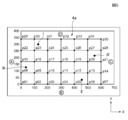
- FIG. 5 is a schematic diagram showing a plurality of reference points and a plurality of pressing points in the present embodiment.
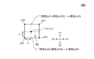
- FIG. 6 is a schematic diagram showing pressing points and four reference points (lattice points) surrounding the pressing points.
- FIG. 7A is a flowchart of calibration of the input device in the present embodiment
- FIG. 7B is a flowchart for explaining a pressing point detection method using the input device in the present embodiment. .
- FIG. 1 is a plan view of the input device according to the present embodiment
- FIG. 2 is a partial longitudinal sectional view of the input device according to the embodiment of the present invention
- FIG. 3 is a block diagram of the input device according to the present embodiment.
- FIG. 4 is an explanatory diagram of the load sensor
- FIG. 4A is a partial longitudinal sectional view
- FIG. 4B is a rear perspective view of a sensor substrate constituting the load sensor.
- the input device 1 in the present embodiment includes a capacitive touch panel sensor 4 and a plurality of load sensors A to D provided on the back surface 4c of the capacitive touch panel sensor 4.
- the capacitive touch panel sensor 4 includes an operation panel formed of translucent glass or plastic, and a translucent sensor layer provided on the back surface of the operation panel.
- the surface of the capacitive touch panel sensor 4 is an operation surface 4a.
- the electrostatic capacitance type touch panel sensor 4 can detect the X coordinate and the Y coordinate of each pressing point even if the operation surface 4a is simultaneously pressed at a plurality of points based on the above-described capacitance change. . It is also possible to use a resistance film type instead of the capacitance type.
- the position coordinates of each pressing point can be detected simultaneously.
- the capacitance type when a plurality of points are simultaneously pressed, the position coordinates of the plurality of pressed points can be detected with higher accuracy.
- the electrostatic touch panel sensor 4 that is translucent has an electrostatic capacity.
- a liquid crystal display (LCD) 3 is displayed through the capacitive touch panel sensor 4, and an input operation on the operation surface 4a is enabled.
- the peripheral portion 4b of the capacitive touch panel sensor 4b is a frame-like opaque decoration region, and the load sensors A to D provided in the decoration region are not visible from the operation surface 4a side. Yes.
- Each load sensor A to D has a sensor substrate 12 and a base substrate 13 as shown in FIG.
- the sensor substrate 12 is provided with a displacement portion 14 and a protruding pressure receiving portion 17 that protrudes in the determination direction of the base substrate 13.
- a predetermined space portion 15 is formed between the sensor substrate 12 and the base substrate 13 so that the displacement portion 14 can be displaced in the height direction when receiving a load.
- a plurality of piezoresistive elements 16 are provided on the back surface of the sensor substrate 12 as strain detecting elements.
- each piezoresistive element 16 When the displacement portion 14 is displaced in the height direction due to the load received by the pressure receiving portion 17, the electric resistance of each piezoresistive element 16 changes according to the amount of displacement, and in the bridge circuit configured by each piezoresistive element 16.
- the sensor output can be obtained by changing the point potential.
- the wiring portion 18 routed from each piezoresistive element 16 is electrically connected to a pad portion (not shown).
- the load sensors A to D in the present embodiment may be other than the configuration shown in FIG.
- the capacitance can be changed based on a change in the distance between the two electrodes when the operation surface 4a is pressed, and the load can be detected by the change in the capacitance.
- the load sensors A to D shown in FIG. 4 may be installed with the pressure receiving portion 17 facing upward.
- the load sensors A to D are disposed on the back surface 4c side of the capacitive touch panel sensor 4. Further, as shown in FIG. 2, a support portion 10 that supports the load sensors A to D is provided, and the support portion 10 and the capacitive touch panel sensor 4 are connected by a connection portion 11 that can be deformed in the height direction. ing. As a result, when the operation surface 4a is pressed, the capacitive touch panel sensor 4 moves downward, and a load can be applied to the load sensors A to D.
- the connection part 11 is a double-sided tape, for example. An elastic body such as rubber may be interposed between the capacitive touch panel sensor 4 and the load sensors A to D.
- the support structure of the load sensors A to D in the touch panel 1 is not limited to that shown in FIG. Further, the positions of the load sensors A to D on the touch panel 1 are not limited to those shown in FIG. 1 (cross arrangement), and may be arranged at, for example, four corners.
- the input device 1 of the present embodiment includes a capacitive touch panel sensor 4, a plurality of load sensors A to D, a capacitive touch panel sensor 4, and a control connected to each of the load sensors A to D. (IC) 2 is provided. Further, data from the control unit 2 can be transmitted to the image display device 20 such as a liquid crystal display (LCD) 3 of the device main body.
- IC capacitive touch panel sensor 4
- IC capacitive touch panel sensor 4
- IC capacitive touch panel sensor 4
- data from the control unit 2 can be transmitted to the image display device 20 such as a liquid crystal display (LCD) 3 of the device main body.
- LCD liquid crystal display
- control unit 2 includes a storage unit 22 and a calculation unit 23.
- the storage unit 22 can store information obtained by calibration, outputs from the capacitive touch panel sensor 4 and the load sensors A to D, and the like.
- calculation unit 23 can calculate each load at each pressing point when a plurality of points on the operation surface 4a are pressed simultaneously.
- the operation surface 4a is divided into a grid in the XY coordinate system. Then, the respective lattice points that intersect with each other in the X direction and the Y direction are set as reference points p01 to p35.
- the horizontal axis shown in FIG. 5 indicates the X coordinate, and the vertical axis indicates the Y coordinate.
- the XY coordinate system is an area of 600 ⁇ 340.
- the position coordinates of the reference points p01 to p35 are stored in the storage unit 22. Although the timing of calibration is not limited, it is assumed here that calibration is performed before shipment of the input apparatus 1.
- step ST1 shown in FIG. 7A the sensitivity at each reference point p01 to p35 in each load sensor A to D is calculated by the calculation unit 23 of the control unit 2.
- the sensitivity (LSB / g) can be obtained by dividing the sensor output by the load.
- the unit LSB of the sensor output is a minimum unit of the digital output, and is a value calculated by the reference voltage and the resolution.
- the unit of output is generally output as a voltage.
- the sensitivity of the load sensor A is the highest and the sensitivity of the load sensor C is the lowest.
- the distance between the reference point p01 and the load sensor A is the closest to the load sensors B to D
- the distance between the reference point p01 and the load sensor C is the load sensors A, B, This is because it is farthest from D.
- the sensitivity increases as the load sensor is closer to the pressing point, and decreases as the load sensor is further away.
- the calibration is completed in steps ST1 and ST2 in FIG. Therefore, at the time of shipment, the calibration of the input device 1 is in a completed state. Note that a user who has purchased the input device 1 can also perform calibration, and this case will be described later.
- FIG. 7B shows steps up to the calculation of the load at each pressing point when the user who has purchased the input device 1 simultaneously presses the operation surface 4a with a plurality of pressing points.
- step ST3 of FIG. 7B it is detected whether or not the operation surface 4a is pressed. Whether or not it has been pressed can be determined, for example, when the total change amount of the sensor outputs of the load sensors A to D has reached a predetermined level or more, or the capacitive touch panel 4 detects the position. It may be determined that the time has been pressed.
- step ST4 the number of pressing points and the position coordinates of the pressing points I to IV are acquired from the capacitive touch panel sensor 4.
- the capacitive touch panel sensor 4 since the capacitive touch panel sensor 4 is used as the position detection sensor, the number of pressing points and the position coordinates of the pressing points I to IV can be detected easily and appropriately. That is, the capacitive touch panel sensor 4 has, for example, a configuration including a large number of X electrodes and a large number of Y electrodes, and a capacitance change between an operating body such as a finger and an X electrode close to the operating body. , And an electrostatic capacity change occurs between the operating body and the Y electrode close to the operating body. Therefore, by detecting which electrode has caused the capacitance change, the number of pressing points and the position coordinates of each pressing point can be detected even when a plurality of pressing points are simultaneously pressed. Table 2 shows the position coordinates of the pressing points I to IV.
- step ST5 of FIG. 7B sensor outputs of the load sensors A to D are acquired.
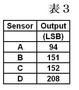
- Table 3 lists the sensor output of each load sensor I-IV.
- the position coordinates of the pressing point I are shown in Table 2 as specific numerical values, but are expressed as (x1, y1) below.
- the position coordinates of the pressing point II are (x2, y2)
- the position coordinates of the pressing point III are (x3, y3)
- the position coordinates of the pressing point IV are (x4, y4).
- the sensor output of the load sensor A (Out A), the sensor output of the load sensor B (Out B), the sensor output of the load sensor C (Out C), and the sensor output of the load sensor D (Out D) are the pressing points. It is represented by the product of the load of I and the sensitivity of each of the load sensors A to D, and is expressed by Equation 1 below.
- a (x1, y1) in Formula 1 indicates the sensitivity of the load sensor A when the pressing point I is pressed
- b (x1, y1) indicates the sensitivity of the load sensor B
- y1) indicates the sensitivity of the load sensor C
- d (x1, y1) indicates the sensitivity of the load sensor D.
- Z (1) indicates a load when the pressing point I is pressed.
- the sensor output (Out A) of the load sensor A in Expression 2 will be described.
- the sensitivity a (x1, y1) is the sensitivity of the load sensor A when the pressing point I is pressed alone
- the sensitivity a ( x2, y2) is the sensitivity of the load sensor A when it is assumed that the pressing point II is pressed alone
- the sensitivity a (x3, y3) is the load when it is assumed that the pressing point III is pressed alone.
- the sensitivity of the sensor A, and the sensitivity a (x4, y4) is the sensitivity of the load sensor A when it is assumed that the pressing point IV is pressed alone.
- the load Z (1) is a load when the pressing point I is pressed
- the load Z (2) is a load when the pressing point II is pressed
- the load Z (3) is the pressing point III. It is a load at the time of pressing
- load Z (4) is a load at the time of pressing pressing point IV. Accordingly, the sensor output (Out A) of the load sensor A is the product of the sensitivities a (x1, y1) to a (x4, y4) at each pressing point and the loads Z (1) to Z (4) at each pressing point.
- the sensor output (Out B) of the load sensor B, the sensor output (Out C) of the load sensor C, and the sensor output (Out D) of the load sensor D shown in Formula 2 are considered in the same way as the sensor output of the load sensor A. be able to.
- Each sensitivity shown in Formula 2 is a different value. For example, looking at the sensor output (Out A) of the load sensor A, the closest pressing point to the load sensor A is III, then I, then II, and the farthest is IV. Therefore, it can be predicted that the sensitivity a (x3, y3) is the largest and the sensitivity a (x4, x4) is the smallest.
- the pressing point I is considered. As shown in FIG. 6, the pressing point I exists in a minimum lattice (minimum rectangular region) 30 connecting the four reference points p23, p24, p30, and p31 adjacent to the pressing point I.
- step ST6 shown in FIG. 7B based on the position coordinates of the pressing point I and the position coordinates of the reference points p23, p24, p30, p31 close to the pressing point I,
- the position ratio of the pressing point I is calculated by the calculation unit 23 of the control unit 2.
- the position coordinates of the reference points p23, p24, p30, and p31 and the position coordinates of the pressing point I are acquired from the storage unit 22, and the table is shown in Table 4 below.
- the sensitivity of each of the reference points p23, p24, p30, and p31 is a value obtained by calibration and extracted from Table 1.
- Equation 3 the position ratio u in the X direction of the pressing point I in the minimum lattice 30 was obtained using the X coordinate of the reference point p23 as the reference position. Further, the position ratio v in the Y direction of the pressing point I in the minimum lattice 30 was obtained using the Y coordinate of the reference point p23 as the reference position.
- the position ratio in the X direction was 0.4
- the position ratio in the Y direction was 0.412. That is, in the minimum lattice 30 shown in FIG. 6, when the length in the X direction is 1, the pressing point I is separated from the position of the reference point p23 in the X1 direction by the length of the ratio 0.4. In the minimum grid 30 shown in FIG. 6, when the length in the Y direction is 1, the pressing point I is in the Y1 direction by the length of the ratio 0.412 from the position of I ′. Exists at a position (x1, y1) apart from each other.
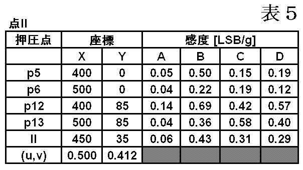
- Table 5 shows the position coordinates of the reference points p5, p6, p12, and p13 used to obtain the position ratios u and v of the pressing point II, the sensitivity of each load sensor A to D at each reference point, and the pressing point.
- the position coordinates of II, the sensitivity of each of the load sensors A to D at the pressing point II, and the position ratios u and v of the pressing point II within the minimum grid are listed.
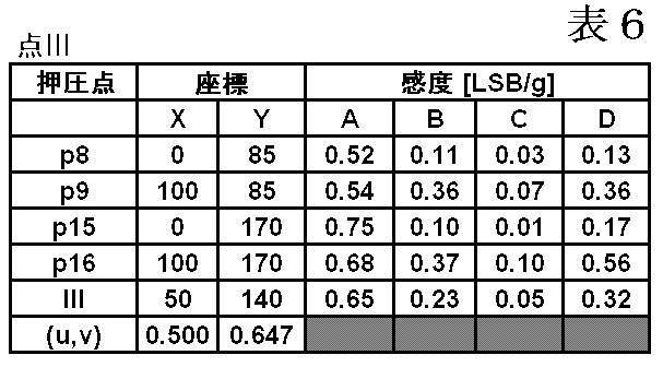
- Table 6 shows the position coordinates of the reference points p8, p9, p15, and p16 used to obtain the position ratios u and v of the pressing point III, the sensitivity of each load sensor A to D at each reference point, and the pressing point III.
- the position coordinates, the sensitivity of each of the load sensors A to D at the pressing point III, and the position ratios u and v of the pressing point III within the minimum grid are listed.
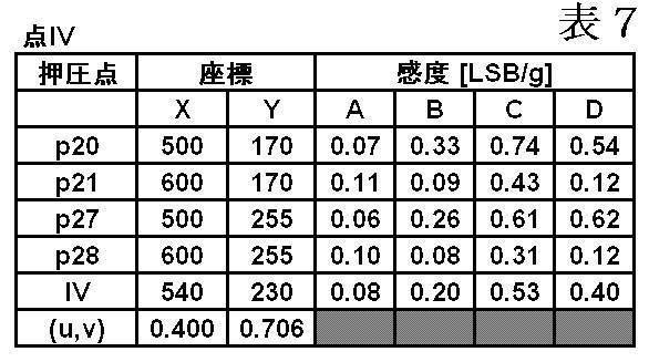
- Table 7 shows the position coordinates of the reference points p20, p21, p27, and p28 used to obtain the position ratios u and v of the pressing point IV, the sensitivity of each load sensor A to D at each reference point, and the pressing point IV.
- the position coordinates, the sensitivity of each load sensor A to D at the pressing point IV, and the position ratios u and v of the pressing point IV within the minimum grid are listed.
- step ST7 of FIG. 7 (b) the calculation unit 23 of the control unit 2 calculates the sensitivities of the load sensors A to D at the pressing points I to IV.
- the sensitivity at the pressing point I will be described.
- the sensitivity changes in proportion to the length ratio between the point p31 and the point p31. That is, for example, considering the sensitivity of the load sensor A at the pressing point I (see Table 4), the sensitivity at the reference point p23 is 0.54, and the sensitivity at the reference point p24 is 0.40. The sensitivity of the load sensor A at the intermediate point between the reference point p23 and the reference point p24 is assumed to be 0.47.
- the sensitivity changes in a linear function with respect to the X direction and the Y direction in the minimum lattice 30 shown in FIG. 6 (as described above, for example, at an intermediate point between the reference point p23 and the reference point p24). Even if the sensitivity of each of the load sensors A to D at the pressing point I is determined (assuming that the sensitivity of the reference point p23 is an intermediate value between the reference point p23 and the reference point p24), the actual sensitivity at the pressing point I and the pressing point I The difference from the calculated sensitivity (sensitivity error) can be kept small.
- the sensitivity of each load sensor A to D in the minimum grid 30 is proportionally converted with respect to the sensitivity at each reference point p23, p24, p30, p31 constituting the minimum grid 30.
- the sensitivity at the position of I ′ shown in FIG. 6 can be expressed as ⁇ sensitivity (p24) ⁇ sensitivity (p23) ⁇ ⁇ u + sensitivity (p23), and the sensitivity at the position of I ′′ is ⁇ sensitivity (p31) ⁇ sensitivity (p30) ⁇ ⁇ u + sensitivity (p30).
- the sensitivity at the pressing point I can be expressed by the following mathematical formula 4.
- Equation 4 shows the sensitivity of the load sensor A at the pressing point I.
- the sensitivity of the load sensor A at each of the pressing points II to IV and the sensitivity of the load sensors B to D at the pressing points I to IV can also be obtained according to Equation 4.
- “A” at the pressing point I in the “Sensitivity” column shown in Table 8 indicates the sensitivity of the load sensor A at the pressing point I, corresponds to the sensitivity a (x1, y1) of Equation 2, and at the pressing point I.
- “B” corresponds to the sensitivity b (x1, y1) of Expression 2
- “C” at the pressing point I corresponds to the sensitivity c (x1, y1) of Expression 2
- “B” at the pressing point I “D” corresponds to the sensitivity d (x1, y1) of Equation 2.
- Equation 5 Equation 5 below is obtained.
- Equation 5 the calculation in Formula 5 is performed by the calculation unit 23 of the control unit 2.
- the load Z (1) at the pressing point I is 100
- the load Z (2) at the pressing point II is 202
- the load Z (3) at the pressing point III is 50
- the sensitivity at the plurality of reference points p01 to p35 on the operation surface 4a is previously held by calibration (FIG. 7A, Table 1).
- a plurality of points a plurality of pressing points I to IV
- position ratios u and v of the pressing points I to IV are obtained (Tables 4 to 7, FIG. Step ST6) of b).
- the position ratios u and v are the minimum grid that is surrounded by the position coordinates of the pressing points I to IV obtained in step ST4 of FIG. 7B and the pressing points I to IV extracted from the table of Table 1. Can be obtained from the position coordinates at a plurality of reference points constituting.
- the sensitivity at each pressing point I to IV is obtained based on the sensitivity at each reference point constituting the minimum grid and the position ratios u and v of each pressing point I to IV (Tables 4 to 7, FIG. Step ST7 of 7 (b).
- the load Z at each of the pressing points I to IV can be calculated (Table 8, FIG. 7B). Step ST8).
- the load at each pressing point can be obtained even if the number of simultaneously pressed points is the same as the number of load sensors A to D. That is, in the above embodiment, since four load sensors A to D are provided, the load Z at each of the pressing points I to IV can be obtained even if the operation surface 4a is simultaneously pressed at four places. As shown in Equations 2 and 5, a simultaneous linear equation consisting of the same number of equations as the number of load sensors can be obtained. At this time, the unknown is only the load at each pressing point, and the unknown is Since the number is equal to the number of equations of the linear equation, simultaneous linear equations can be solved. As a matter of course, when four load sensors A to D are provided and the number of pressing points on the operation surface 4a is one to three, the load at each pressing point can be obtained by the above formula. Can do.
- the number of load sensors is not particularly limited as long as it is two or more. Particularly, when the number of pressing points is more than three points, the calculation when calculating the load at each pressing point becomes extremely complicated in the conventional method, Or since calculation becomes impossible, it is suitable that there are four or more load sensors.
- the calibration shown in FIG. 7A may be performed by the user before shipment or after shipment.
- the reference points p01 to p35 shown in FIG. 5 are displayed on at least the operation surface 4a shown in FIG. 1, and the user sequentially presses the reference points p01 to p35 with a finger or a pen.
- the sensitivity at each of the reference points p01 to p35 may be obtained. It is preferable to make a sound or display for notifying the user that the sensitivity detection is completed when the predetermined load is reached when pressed.
- the user can perform calibration after performing calibration before shipment.
- the user may press all of the reference points p01 to p35 shown in FIG. 5, but the sensitivity at the pressed reference points is obtained by pressing some reference points. It is detected how much sensitivity error has occurred compared to the sensitivity data by the application.
- the sensitivity at the remaining reference points can be obtained by comparing sensitivity data obtained by calibration before shipment and the sensitivity error value obtained by pressing a specific reference point.
- the pressing points I to IV when the position ratios u and v of the pressing points I to IV are obtained, the pressing points I to IV within the minimum grid surrounded by the four reference points close to the pressing points I to IV are determined. It is preferable to obtain the position ratio u in the X direction and the position ratio v in the Y direction.
- the reference points p15 that are lattice points in a slightly larger area, without using the reference points p23, p24, p30, and p31 constituting the minimum lattice.
- the position ratios u and v of the pressing point I in the region can be obtained.
- the pressing point I is surrounded.
- the sensitivity error can be reduced by obtaining the sensitivity at each of the press points I to IV within the region surrounded by the reference point close to each of the press points I to IV.
- the lattice points intersecting the X direction and the Y direction are set as the reference points p01 to p35, and the minimum is surrounded by the four reference hands close to the pressing points I to IV. It is preferable to obtain the position ratios u and v at the respective pressing points I to IV on the lattice.
- each intersection obtained by obliquely intersecting the X direction and the Y direction can be used as the reference point.
- the shape in which the four reference points adjacent to each other around the pressing point are linearly connected is not a rectangular or square lattice shape as shown in FIG. 5, but a rhombus.
- the grid points intersecting in the X direction and the Y direction are set as reference points p01 to p35, and the position ratios of the respective pressing points I to IV in the minimum grid are obtained. It is easy to calculate u and v, the calculation burden on the control unit 2 can be reduced, and the loads at the respective pressing points I to IV can be obtained quickly and accurately. In addition, the sensitivity error at each of the pressing points I to IV can be reduced.
- the input device (touch panel) 1 in this embodiment can be applied to a mobile phone, a portable information processing device, a portable storage device, a portable game device, and the like.
Landscapes
- Engineering & Computer Science (AREA)
- General Engineering & Computer Science (AREA)
- Theoretical Computer Science (AREA)
- Human Computer Interaction (AREA)
- Physics & Mathematics (AREA)
- General Physics & Mathematics (AREA)
- Position Input By Displaying (AREA)
- Force Measurement Appropriate To Specific Purposes (AREA)
Description
本発明は、携帯機器やその他の電子機器に搭載されて、指などを操作パネルに接触させて操作する入力装置に関する。
以下に示す特許文献1~4には、操作面上を指等で操作した際の押圧点の位置座標と荷重とを検出できる入力装置が記載されている。
これら特許文献にて、位置座標と荷重との双方の検出を可能とする押圧点は一点であり、同時に複数箇所を押圧したときの各押圧点での荷重の検出については何も記載されていない。
また、特許文献5~7には、荷重センサが操作面下に配置された構成が開示されている。そしてこれら特許文献には荷重センサの感度に関する記載がある。しかしながら、特許文献1~4と同様に、操作面上を同時に複数の位置で押圧したとき、各押圧点の荷重の検出については何も記載されていない。
本発明は上記従来の課題を解決するものであり、複数個所を同時に押圧したときであっても煩雑な計算を行うことなく、同時押しした複数の押圧点の各荷重を得ることが可能な入力装置及び前記入力装置を用いた複数点の荷重検出方法を提供することを目的としている。
本発明における入力装置は、操作面上での押圧位置を検出可能な位置検出センサと、荷重に応じたセンサ出力を出力する複数の荷重センサと、前記操作面上に同時に押圧された複数の押圧点の各荷重を以下の処理により算出する制御部と、を有することを特徴とするものである。
(1) 前記操作面上の異なる複数の基準点での感度を、各荷重センサのセンサ出力から算出し、前記感度を保持しておくこと。
(2) 前記操作面上が複数の前記押圧点により同時に押圧されたとき、各荷重センサからセンサ出力を得るとともに、前記位置検出センサから各押圧点の位置座標を検出すること。
(3) 各押圧点及び各基準点の位置座標に基づいて、各押圧点に近接する複数の前記基準点により囲まれる領域内での各押圧点の位置比率を求めること。
(4) 各押圧点の感度を、前記(3)で用いた各基準点の感度及び各押圧点の位置比率に基づいて求めること。
(5) 前記(4)で得られた各押圧点の感度、及び、前記(2)で得られた各荷重センサのセンサ出力に基づいて、各押圧点の荷重を算出すること。
(1) 前記操作面上の異なる複数の基準点での感度を、各荷重センサのセンサ出力から算出し、前記感度を保持しておくこと。
(2) 前記操作面上が複数の前記押圧点により同時に押圧されたとき、各荷重センサからセンサ出力を得るとともに、前記位置検出センサから各押圧点の位置座標を検出すること。
(3) 各押圧点及び各基準点の位置座標に基づいて、各押圧点に近接する複数の前記基準点により囲まれる領域内での各押圧点の位置比率を求めること。
(4) 各押圧点の感度を、前記(3)で用いた各基準点の感度及び各押圧点の位置比率に基づいて求めること。
(5) 前記(4)で得られた各押圧点の感度、及び、前記(2)で得られた各荷重センサのセンサ出力に基づいて、各押圧点の荷重を算出すること。
また本発明における入力装置の押圧点検出方法は、
操作面上での押圧位置を検出可能な位置検出センサと、荷重に応じたセンサ出力を出力する複数の荷重センサと、前記操作面上に同時に押圧された複数の押圧点の各荷重を算出する制御部と、を有する入力装置を用いて、
(1) 前記操作面上の異なる複数の基準点での感度を、各荷重センサのセンサ出力から算出し、前記感度を保持するステップ、
(2) 前記操作面上が複数の前記押圧点により同時に押圧されたとき、各荷重センサからセンサ出力を得るとともに、前記位置検出センサから各押圧点の位置座標を検出するステップ、
(3) 前記制御部にて、各押圧点及び各基準点の位置座標に基づき、各押圧点に近接する複数の前記基準点により囲まれる領域内での各押圧点の位置比率を求めるステップ、
(4) 前記制御部にて、各押圧点の感度を、前記(3)で用いた各基準点の感度及び各押圧点の位置比率に基づいて求めるステップ、
(5) 前記制御部にて、前記(4)で得られた各押圧点の感度、及び、前記(2)で得られた各荷重センサのセンサ出力に基づいて、各押圧点の荷重を算出するステップ、
を有することを特徴とするものである。
操作面上での押圧位置を検出可能な位置検出センサと、荷重に応じたセンサ出力を出力する複数の荷重センサと、前記操作面上に同時に押圧された複数の押圧点の各荷重を算出する制御部と、を有する入力装置を用いて、
(1) 前記操作面上の異なる複数の基準点での感度を、各荷重センサのセンサ出力から算出し、前記感度を保持するステップ、
(2) 前記操作面上が複数の前記押圧点により同時に押圧されたとき、各荷重センサからセンサ出力を得るとともに、前記位置検出センサから各押圧点の位置座標を検出するステップ、
(3) 前記制御部にて、各押圧点及び各基準点の位置座標に基づき、各押圧点に近接する複数の前記基準点により囲まれる領域内での各押圧点の位置比率を求めるステップ、
(4) 前記制御部にて、各押圧点の感度を、前記(3)で用いた各基準点の感度及び各押圧点の位置比率に基づいて求めるステップ、
(5) 前記制御部にて、前記(4)で得られた各押圧点の感度、及び、前記(2)で得られた各荷重センサのセンサ出力に基づいて、各押圧点の荷重を算出するステップ、
を有することを特徴とするものである。
本発明では、(1)で示すように、予め、操作面上における複数の基準点での感度を保持しておき、操作面上にて複数点(複数の押圧点)が同時押しされたら、まず(2)で、各荷重センサのセンサ出力及び各押圧点の位置座標を検出した後、(3)で各押圧点に近接する複数の基準点により囲まれた領域内での各押圧点の位置比率を求める。位置比率は、各押圧点及び各基準点での位置座標により求めることができる。続いて(4)にて、各押圧点の感度を、各基準点の感度及び各押圧点の位置比率に基づいて求める。そして、(5)では、各押圧点の感度、及び荷重センサのセンサ出力に基づいて、各押圧点の荷重を算出することができる。
本発明によれば、同時押しされた複数の押圧点の荷重を複雑な計算を用いることなく適切かつ簡単に求めることができる。
特に本発明の入力装置及び押圧点検出方法によれば、同時押しされた複数の押圧点数を荷重センサの数と同数としても各押圧点の荷重を求めることができる。すなわち、例えば荷重センサを4つ設けた場合、同時押しされた押圧点数が4つ以内であれば、各押圧点の荷重を求めることができる。
本発明では、XY座標系において、X方向及びY方向に交差してなる各格子点を前記基準点とし、前記(3)では、各押圧点に近接する4点の基準点により囲まれる最小格子内での各押圧点のX方向の位置比率u及びY方向の位置比率vを求めることが好ましい。これにより各押圧点での感度誤差を小さくでき、各押圧点の荷重を精度よく求めることができる。
本発明では前記荷重センサが4つ以上設けられることが好ましい。これにより、同時押しされた押圧点数が荷重センサと同数にの4点以上であっても、各押圧点の荷重を求めることができる。
本発明によれば、同時押しされた複数の押圧点の荷重を複雑な計算を用いることなく適切かつ簡単に求めることができる。
特に本発明の入力装置及び押圧点検出方法によれば、同時押しされた複数の押圧点数を荷重センサの数と同数としても各押圧点の荷重を求めることができる。すなわち、例えば荷重センサを4つ設けた場合、同時押しされた各押圧点が4か所以内であれば、各押圧点の荷重を求めることができる。
図1は、本実施形態における入力装置の平面図であり、図2は、本発明の実施形態における入力装置の部分縦断面図であり、図3は、本実施形態の入力装置のブロック図であり、図4は、荷重センサの説明図であり、図4(a)は部分縦断面図、図4(b)は、荷重センサを構成するセンサ基板の裏面透視図である。
本実施形態における入力装置1は、静電容量式タッチパネルセンサ4と、静電容量式タッチパネルセンサ4の裏面4cに設けられた複数の荷重センサA~Dとを有して構成される。
静電容量式タッチパネルセンサ4は、透光性のガラスやプラスチック等で形成された操作パネルと、操作パネルの裏面に設けられた透光性のセンサ層とを有して構成される。静電容量式タッチパネルセンサ4の表面が操作面4aである。
静電容量式タッチパネル4の操作面4aを指等の操作体で押圧すると、静電容量変化が生じ、静電容量変化に基づき操作体の押圧位置(操作位置)を検出することが可能である。静電容量式タッチパネルセンサ4では、上記した静電容量変化に基づき、操作面4a上を複数点にて同時押ししても、各押圧点のX座標及びY座標を検出することが可能である。また静電容量式でなく抵抗膜式等とすることも可能である。抵抗膜式の場合、同じ平面の抵抗層を複数に分離する等で、複数点を同時に押圧した時、各押圧点の位置座標の同時検出を可能とする。ただし静電容量式とすることで、複数点を同時に押圧した場合において複数の押圧点の各位置座標をより精度良く検出することができる。
図2に示すように、静電容量式タッチパネルセンサ4の周囲部4bの裏面4cに加飾層9を設けることで、透光性である静電容量式タッチパネルセンサ4の中央部分では、静電容量式タッチパネルセンサ4を通して液晶ディスプレイ(LCD)3の表示がされ操作面4a上での入力操作が可能とされている。また静電容量式タッチパネルセンサ4bの周囲部4bでは、額縁状の不透明な加飾領域であり、加飾領域に設けられた各荷重センサA~Dは操作面4a側から見えないようになっている。
各荷重センサA~Dは、図4に示すように、センサ基板12と、ベース基板13とを有する。センサ基板12には、変位部14と、ベース基板13の判定方向に向けて突出する突起状の受圧部17が設けられる。センサ基板12とベース基板13との間には所定の空間部15が形成されており、これにより変位部14が荷重を受けると高さ方向に変位できるようになっている。図4(a)(b)に示すように、センサ基板12の裏面には、歪検出素子として複数のピエゾ抵抗素子16が設けられる。受圧部17で受けた荷重により変位部14が高さ方向に変位すると、その変位量に応じて各ピエゾ抵抗素子16の電気抵抗が変化し、各ピエゾ抵抗素子16によって構成されたブリッジ回路の中点電位が変化することで、センサ出力を得ることが出来る。図4(b)に示すように各ピエゾ抵抗素子16から引き回された配線部18が図示しないパッド部と電気的に接続されている。
本実施形態における荷重センサA~Dは図4に示した構成以外のものであってもよい。例えば操作面4aを押圧したときに2つの電極間の距離の変化に基づいて静電容量が変化し、この静電容量変化により荷重を検出することが可能な構成にすることも可能である。また図4に示す荷重センサA~Dは、受圧部17が上方を向いた状態で設置されてもよい。
図1,図2に示すように、荷重センサA~Dは、静電容量式タッチパネルセンサ4の裏面4c側に配置される。また図2に示すように、荷重センサA~Dを支える支持部10を備え、この支持部10と静電容量式タッチパネルセンサ4との間が高さ方向に変形可能な接続部11により接続されている。これにより操作面4aを押圧したときに静電容量式タッチパネルセンサ4が下方に移動し、荷重センサA~Dに荷重を加えることができる。接続部11は例えば両面テープである。なお静電容量式タッチパネルセンサ4と荷重センサA~Dとの間に、ゴム等の弾性体が介在した構成としてもよい。
なおタッチパネル1における荷重センサA~Dの支持構造は図2に示すものに限定されない。また、タッチパネル1における荷重センサA~Dの位置は図1に示すもの(十字配置)に限定されず、例えば、四隅に配置されてもよい。
図3に示すように本実施形態の入力装置1は、静電容量式タッチパネルセンサ4、複数の荷重センサA~D、静電容量式タッチパネルセンサ4及び各荷重センサA~Dに接続される制御部(IC)2を備える。また制御部2からのデータを機器本体部の液晶ディスプレイ(LCD)3等の画像表示装置20に送信できるようになっている。
図3に示すように、制御部2は、記憶部22及び算出部23を有して構成されている。記憶部22では、キャリブレーションにより得られた情報や静電容量式タッチパネルセンサ4及び荷重センサA~Dからの出力等を記憶することができる。
また算出部23では、操作面4a上の複数点を同時押ししたときに各押圧点の各荷重等を算出することが可能とされている。
以下では、図5~図7を用いて、同時押しした各押圧点の各荷重を求めるアルゴリズムについて説明する。また表1~表8に示すように具体的な数値を用いて説明することとする。
まずキャリブレーションを行うが、その際、図5に示すように、操作面4aをXY座標系において格子状に区切る。そしてX方向及びY方向にて交差した点である各格子点を基準点p01~p35とする。図5に示す横軸はX座標を示し、縦軸はY座標を示している。この実施例ではXY座標系を600×340のエリアとした。
各基準点p01~p35の位置座標は記憶部22に保存されている。
なおキャリブレーションのタイミングについて限定するものではないが、ここでは入力装置1の出荷前にキャリブレーションを行うとして説明する。
なおキャリブレーションのタイミングについて限定するものではないが、ここでは入力装置1の出荷前にキャリブレーションを行うとして説明する。
出荷前に、一定の荷重をかけながら各基準点p01~p35を順次押圧する。すなわち各基準点p01~p35は同時押しせず一つずつ順番に一定の荷重で押圧する。このとき、各荷重センサA~Dからセンサ出力を得ることができる。図7(a)に示すステップST1では、各荷重センサA~Dにおける各基準点p01~p35での感度を制御部2の算出部23で算出する。ここで、各荷重センサA~Dのセンサ出力(LSB)と荷重(g)がわかっているから、センサ出力を荷重で割ることで、感度(LSB/g)を得ることができる。ここで、センサ出力の単位LSBとは、デジタル出力の最小単位であり、基準電圧と分解能によって計算される値である。センサがアナログ出力の場合には、出力の単位は一般的に電圧として出力される。
そして、基準点p01~p35の位置座標及び感度を備える以下の表1のテーブルを記憶部22に保存する(図7(a)のステップST2)。

表1に示すように基準点p01(位置座標(X,Y)の格子点)を押圧したとき、荷重センサAの感度が最も大きくなっており、荷重センサCの感度が最も小さくなっている。これは図5に示すように基準点p01と荷重センサAとの距離は、荷重センサB~Dに比べて最も近く、また基準点p01と荷重センサCとの距離は、荷重センサA,B,Dに比べて最も遠いためである。このように、感度は、荷重センサが押圧点に近いほど大きくなるし、遠いほど小さくなる。
図7(a)のステップST1,ST2によりキャリブレーションが終了する。よって出荷時、入力装置1のキャリブレーションは完了した状態にある。なお入力装置1を購入したユーザーが、キャリブレーションを実行することも可能であるが、その場合については後述することとする。
図7(b)は、入力装置1を購入したユーザーが操作面4aを複数の押圧点により同時押ししたとき、各押圧点の荷重算出までのステップを示している。
図7(b)のステップST3では、操作面4aが押圧されたか否かを検出する。押圧されたか否かは、例えば、各荷重センサA~Dのセンサ出力の合計変化量が所定以上の大きさとなったときに押圧されたと判断できるし、あるいは、静電容量式タッチパネル4が位置検知したときを押圧されたと判断としても良い。
なお、押圧点が一点ということもあるが、以下では、図5に示すように押圧点I~IVが4点であるとして説明する。
ステップST4では、静電容量式タッチパネルセンサ4から押圧点数及び各押圧点I~IVの位置座標を取得する。
本実施形態では、位置検出センサとして静電容量式タッチパネルセンサ4を用いたため、押圧点数及び各押圧点I~IVの位置座標を簡単かつ適切に検出することが可能である。すなわち、静電容量式タッチパネルセンサ4は、例えば多数のX電極及び多数のY電極を備えた構成であり、指等の操作体と、操作体に近いX電極との間での静電容量変化、及び操作体と、操作体に近いY電極との間での静電容量変化が生じる。よってどの電極にて静電容量変化が生じたかを検出することで、複数の押圧点が同時押しされても、押圧点数及び各押圧点の位置座標を検出することができる。表2に、各押圧点I~IVの位置座標を掲載した。

次に、図7(b)のステップST5では、各荷重センサA~Dのセンサ出力を取得する。表3に、各荷重センサI~IVのセンサ出力を掲載した。
押圧点Iの位置座標は具体的な数値として表2に示されているが、以下、(x1,y1)と表記する。加えて、押圧点IIの位置座標は(x2、y2)、押圧点IIIの位置座標は(x3、y3)、押圧点IVの位置座標は(x4、y4)と表記する。
ここで例えば、押圧点がIの一点だけだったとする。このとき、荷重センサAのセンサ出力(Out A)、荷重センサBのセンサ出力(Out B)、荷重センサCのセンサ出力(Out C)、及び荷重センサDのセンサ出力(Out D)は押圧点Iの荷重と各荷重センサA~Dの感度との積で表され、以下の数式1にて示される。

ここで数式1中におけるa(x1,y1)は、押圧点Iを押圧した際の荷重センサAの感度を示し、b(x1,y1)は、荷重センサBの感度を示し、c(x1,y1)は、荷重センサCの感度を示し、d(x1,y1)は、荷重センサDの感度を示す。またZ(1)は、押圧点Iを押圧した際の荷重を示す。
したがって図5で示すように押圧点がI~IVの4点である場合、荷重センサAのセンサ出力(Out A)、荷重センサBのセンサ出力(Out B)、荷重センサCのセンサ出力(Out C)、及び荷重センサDのセンサ出力(Out D)は以下の数式2にて示される。

数式2の荷重センサAのセンサ出力(Out A)について説明すると、感度a(x1,y1)は、押圧点Iを単独で押圧したと仮定したときの荷重センサAの感度であり、感度a(x2,y2)は、押圧点IIを単独で押圧したと仮定したときの荷重センサAの感度であり、感度a(x3,y3)は、押圧点IIIを単独で押圧したと仮定したときの荷重センサAの感度であり、感度a(x4,y4)は、押圧点IVを単独で押圧したと仮定したときの荷重センサAの感度である。また荷重Z(1)は、押圧点Iを押圧した際の荷重であり、荷重Z(2)は、押圧点IIを押圧した際の荷重であり、荷重Z(3)は、押圧点IIIを押圧した際の荷重であり、荷重Z(4)は、押圧点IVを押圧した際の荷重である。従って、荷重センサAのセンサ出力(Out A)は各押圧点の感度a(x1,y1)~a(x4,y4)と各押圧点の荷重Z(1)~Z(4)のそれぞれの積の和として表すことが出来る。数式2に示す荷重センサBのセンサ出力(Out B)、荷重センサCのセンサ出力(Out C)、荷重センサDのセンサ出力(Out D)についても、荷重センサAのセンサ出力と同じように考えることができる。なお、数式2に示す各感度は、それぞれ異なった値である。例えば、荷重センサAのセンサ出力(Out A)で見てみると、荷重センサAに最も近い押圧点は、IIIであり、続いてIであり、続いてIIであり、もっとも遠いのがIVであるので、感度a(x3,y3)が最も大きく、感度a(x4,x4)が最も小さくなると予測できる。また、押圧点Iでの各荷重センサA~Dにおける感度a(x1,y1)、b(x2,y2)、c(x3,y3)、d(x4,y4)を見てみても、押圧点Iに最も近い荷重センサは、Dであり、続いてAであり、続いてBであり、もっとも遠いのがCであるので、感度d(x1,y1)が最も大きく、感度c(x1,x1)が最も小さくなると予測できる。
ここで押圧点Iについて考察する。図6に示すように押圧点Iは、押圧点Iに近接する4つの基準点p23、p24、p30及びp31を結んだ最小格子(最小の矩形領域)30内に存在している。
本実施形態では、図7(b)に示すステップST6において、押圧点Iの位置座標及び押圧点Iに近接した各基準点p23、p24、p30、p31の位置座標に基づいて、最小格子30内における押圧点Iの位置比率を、制御部2の算出部23により求める。ここで、基準点p23、p24、p30、p31の位置座標及び押圧点Iの位置座標を記憶部22から取得し、そのテーブルを以下の表4に示した。
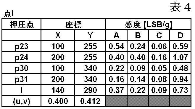
各基準点p23、p24、p30、p31の感度については、キャリブレーションにより取得した値であり表1から抜き出したものである。
なお表4には、押圧点Iにおける各荷重センサA~Dの感度が記入されているが、これら感度は現時点では不明である。この押圧点Iでの各荷重センサA~Dの感度を求めるために、最小格子30内における押圧点Iの位置比率u、vを求める。X方向の位置比率u及びY方向の位置比率vを以下の数式3により求めた。

数式3によれば、最小格子30内での押圧点IのX方向における位置比率uを、基準点p23のX座標を基準位置として求めた。また最小格子30内での押圧点IのY方向における位置比率vを、基準点p23のY座標を基準位置として求めた。
数式3に示すように、X方向の位置比率は0.4であり、Y方向の位置比率は、0.412であった。すなわち、図6に示す最小格子30内において、X方向の長さを1としたとき、押圧点Iは、基準点p23の位置から比率0.4の長さ分だけX1方向に離れたI´の位置に存在し、また、図6に示す最小格子30内において、Y方向の長さを1としたとき、押圧点Iは、I´の位置から比率0.412の長さ分だけY1方向に離れた位置(x1,y1)に存在している。
なお上記と同じようにして押圧点II、押圧点III、及び押圧点IVに近接する4つの基準点により囲まれる最小格子内での各押圧点II、押圧点III、及び押圧点IVの位置比率u、vを、数式3に準じて求めることができる。
以下の表5には、押圧点IIの位置比率u、vを求めるのに用いた基準点p5、p6、p12、p13の位置座標及び各基準点における各荷重センサA~Dの感度、押圧点IIの位置座標、及び押圧点IIにおける各荷重センサA~Dの感度、最小格子内での押圧点IIの位置比率u、vが掲載されている。
表6には、押圧点IIIの位置比率u、vを求めるのに用いた基準点p8、p9、p15、p16の位置座標及び各基準点における各荷重センサA~Dの感度、押圧点IIIの位置座標、及び押圧点IIIにおける各荷重センサA~Dの感度、最小格子内での押圧点IIIの位置比率u、vが掲載されている。
表7には、押圧点IVの位置比率u、vを求めるのに用いた基準点p20、p21、p27、p28の位置座標及び各基準点における各荷重センサA~Dの感度、押圧点IVの位置座標、及び押圧点IVにおける各荷重センサA~Dの感度、最小格子内での押圧点IVの位置比率u、vが掲載されている。
次に図7(b)のステップST7では、制御部2の算出部23により各押圧点I~IVにおける各荷重センサA~Dの感度を算出する。以下、押圧点Iでの感度について説明する。
本実施形態では、押圧点Iを囲む、基準点p23と基準点p24との間、基準点p23と基準点p30との間、基準点p30と基準点p31との間、及び基準点p24と基準点p31との間では、感度が長さの比率に比例して変化していると仮定する。すなわち例えば押圧点Iでの荷重センサAの感度(表4参照)について考察すると、基準点p23での感度は、0.54であり、基準点p24での感度は、0.40であるため、基準点p23と基準点p24の中間点における荷重センサAの感度を、0.47と仮定する。
既に述べたように、押圧点が荷重センサに近ければ近いほど(遠ければ遠いほど)、感度は大きくなる(小さくなる)。このとき、図6に示す最小格子30内では感度がX方向及びY方向に対して一次関数的に変化しているとみなして(上記のように例えば基準点p23と基準点p24の中間点での感度が、基準点p23と基準点p24との中間値とみなして)押圧点Iにおける各荷重センサA~Dの感度を求めても、押圧点Iでの実際の感度と、押圧点Iでの計算された感度との差(感度誤差)を小さく抑えることができる。
上記のように、最小格子30内における各荷重センサA~Dの感度は、最小格子30を構成する各基準点p23、p24、p30、p31での感度に対して比例換算したものであると仮定すると、図6に示すI´の位置における感度は、{感度(p24)-感度(p23)}・u+感度(p23)と示すことができ、I″の位置における感度は、{感度(p31)-感度(p30)}・u+感度(p30)と示すことができる。
そして、押圧点Iは、I´の位置からY1方向に位置比率vにて移動した位置にあるため、押圧点Iでの感度を以下の数式4にて示すことができる。

なお数式4は、押圧点Iにおける荷重センサAの感度を示した。各押圧点II~IVにおける荷重センサA及び押圧点I~IVにおける荷重センサB~Dの感度についても数式4に準じて求めることができる。
以上により、各押圧点I~IVでの各荷重センサA~Dの感度を求めることができた。各押圧点I~IVの位置座標、各押圧点I~IVでの各荷重センサA~Dの感度及び各荷重センサA~Dのセンサ出力をまとめたのが以下の表8である。

表8に示す「感度」欄における押圧点Iでの「A」は、押圧点Iでの荷重センサAの感度を示し、数式2の感度a(x1,y1)に該当し、押圧点Iでの「B」は、数式2の感度b(x1,y1)に該当し、押圧点Iでの「C」は、数式2の感度c(x1,y1)に該当し、押圧点Iでの「D」は、数式2の感度d(x1,y1)に該当する。表8の「感度」欄の各押圧点II~IVでの「A」~「D」と、数式2に示す感度a(x2,y2)~d(x4,y4)との関係についても同様である。
さて、数式2に表8に示す各センサ出力及び各感度を挿入すると、以下の数式5となる。

ここで未知数は、荷重Z(1)~Z(4)の4つである。一方、数式5に示すように連立一次式は4式あるから、数式5を解くことができ、各荷重Z(1)~Z(4)を求めることができる。数式5における計算を制御部2の算出部23にて行う。
数式5を解いた結果、押圧点Iでの荷重Z(1)は、100、押圧点IIでの荷重Z(2)は、202、押圧点IIIでの荷重Z(3)は、50、押圧点IVでの荷重Z(4)は、149であることがわかった(図7(b)のステップST8)。
以上のように、本実施形態では、キャリブレーションにより、予め、操作面4a上における複数の基準点p01~p35での感度を保持しておく(図7(a)、表1)。そして、ユーザーが操作面4a上の複数点(複数の押圧点I~IV)を同時押ししたら、まず各押圧点I~IVの位置比率u、vを求める(表4~表7、図7(b)のステップST6)。位置比率u、vは、図7(b)のステップST4で得た各押圧点I~IVの位置座標と、表1のテーブルから引き出した、各押圧点I~IVに近接して囲む最小格子を構成する複数の基準点での位置座標とから求めることができる。続いて、各押圧点I~IVでの感度を、最小格子を構成する各基準点での感度及び各押圧点I~IVの位置比率u、vに基づいて求める(表4~表7、図7(b)のステップST7)。そして、各押圧点I~IVでの感度、及び各荷重センサA~Dのセンサ感度に基づいて、各押圧点I~IVの荷重Zを算出することができる(表8、図7(b)のステップST8)。
このように本実施形態では、同時押しされた複数の押圧点I~IVの荷重を複雑な計算を用いることなく適切かつ簡単に求めることができる。
特に本実施形態によれば、同時押しされた複数の押圧点数を荷重センサA~Dの数と同数としても各押圧点の荷重を求めることができる。すなわち、上記の実施形態では、荷重センサA~Dを4つ設けているので、操作面4a上を同時に4か所、押しても各押圧点I~IVの荷重Zを求めることができる。これは、数式2,及び数式5に示すように荷重センサの数と同数の式からなる連立一次方程式を得ることができ、このとき未知数は、各押圧点の荷重だけであり、未知数は、連立一次方程式の式の数と同数であるため、連立一次方程式を解くことができる。なお当然のことながら、荷重センサA~Dが4つ設けられた場合において、操作面4a上での押圧点数が1点~3点の場合も、各押圧点の荷重を上記した数式により求めることができる。
また荷重センサの数は2つ以上であれば、特に限定されるものでないが、特に押圧点が3点よりも多くなると従来の方法では各押圧点の荷重を求める際の計算がきわめて煩雑化し、あるいは計算が不能となるため、荷重センサは4つ以上であることが好適である。
図7(a)に示すキャリブレーションは出荷前であっても出荷後、ユーザーが行うものであってもよい。ユーザーが行う場合には、少なくとも図1に示す操作面4a上に図5に示す各基準点p01~p35を表示し、ユーザーが指やペンを用いて、各基準点p01~p35を順次押圧して各基準点p01~p35での感度が得られるようにしてもよい。押圧した際に、所定荷重に到達したらユーザーに感度検出が完了したことを知らせるための音や表示を行うことが好ましい。
また、出荷前にキャリブレーションを行った後、ユーザーがキャリブレーションを行うこともできる。このときユーザーに図5に示す基準点p01~p35すべてを押圧させてもよいが、いくつかの基準点を押圧させるようにして押圧した基準点での感度を求め、このとき、出荷前のキャリブレーションによる感度データと比較してどの程度の感度誤差が生じているかを検出する。残りの基準点での感度については、出荷前のキャリブレーションによる感度データと、特定の基準点を押圧して得られた前記の感度誤差の値とを照合しながら求めることができる。
本実施形態では、各押圧点I~IVの位置比率u、vを求める際、各押圧点I~IVに近接する4点の基準点により囲まれる最小格子内での各押圧点I~IVのX方向の位置比率u及びY方向の位置比率vを求めることが好ましい。例えば、押圧点Iの位置比率u、vを求めるには、最小格子を構成する基準点p23、p24、p30、p31を用いなくても、例えば、もう少し大きな領域の格子点となる基準点p15、p18、p29、p32を用いて、その領域内での押圧点Iの位置比率u、vを求めることもできる。しかしながら、上記したように、位置比率u、vを用いて、押圧点Iを囲む各基準点での感度から比例換算したものを押圧点Iでの感度とみなすのであるから、押圧点Iを囲む領域を大きくするとそれだけ押圧点Iでの感度誤差が生じやすくなる。したがって、各押圧点I~IVに近接する基準点により囲まれる領域内にて、各押圧点I~IVでの感度を求めることで、感度誤差を小さくでき好適である。
また本実施形態では、XY座標系において、X方向及びY方向に交差してなる各格子点を基準点p01~p35とし、各押圧点I~IVに近接する4点の基準手により囲まれる最小格子での各押圧点I~IVでの位置比率u、vを求めることが好適である。例えば、X方向及びY方向のそれぞれを斜めに交差させた各交差点を基準点とすることもできる。ただしかかる構成では、押圧点の周囲にて近接する4点の基準点間を直線状に結んだ形状は、図5に示すような矩形や正方形の格子形状ではなくてひし形などになる。この場合、斜め方向への座標を用いて押圧点の位置比率を求めることが必要になり位置比率の計算が複雑化しやすいし、また感度誤差が生じやすくなる。一方、本実施形態のように、X方向及びY方向に交差してなる格子点を基準点p01~p35とし、最小格子内での各押圧点I~IVの位置比率を求めることで、位置比率u、vを簡単に算出しやすく、制御部2への算出負担を小さくでき、各押圧点I~IVの荷重をスピーディにかつ精度よく求めることができる。しかも各押圧点I~IVでの感度誤差を小さくすることができる。
本実施形態における入力装置(タッチパネル)1は、携帯電話、携帯用の情報処理装置、携帯用の記憶装置、携帯用のゲーム装置などに適用できる。
A~D 荷重センサ
I~IV 押圧点
p01~p35 基準点
u、v 位置比率
1 入力装置
2 制御部
4 静電容量式タッチパネルセンサ
22 記憶部
23 算出部
30 最小格子
I~IV 押圧点
p01~p35 基準点
u、v 位置比率
1 入力装置
2 制御部
4 静電容量式タッチパネルセンサ
22 記憶部
23 算出部
30 最小格子
Claims (4)
- 操作面上での押圧位置を検出可能な位置検出センサと、荷重に応じたセンサ出力を出力する複数の荷重センサと、前記操作面上に同時に押圧された複数の押圧点の各荷重を以下の処理により算出する制御部と、を有することを特徴とする入力装置。
(1) 前記操作面上の異なる複数の基準点での感度を、各荷重センサのセンサ出力から算出し、前記感度を保持しておくこと。
(2) 前記操作面上が複数の前記押圧点により同時に押圧されたとき、各荷重センサからセンサ出力を得るとともに、前記位置検出センサから各押圧点の位置座標を検出すること。
(3) 各押圧点及び各基準点の位置座標に基づいて、各押圧点に近接する複数の前記基準点により囲まれる領域内での各押圧点の位置比率を求めること。
(4) 各押圧点の感度を、前記(3)で用いた各基準点の感度及び各押圧点の位置比率に基づいて求めること。
(5) 前記(4)で得られた各押圧点の感度、及び、前記(2)で得られた各荷重センサのセンサ出力に基づいて、各押圧点の荷重を算出すること。 - XY座標系において、X方向及びY方向に交差してなる各格子点を前記基準点とし、前記(3)では、各押圧点に近接する4点の基準点により囲まれる最小格子内での各押圧点のX方向の位置比率u及びY方向の位置比率vを求める請求項1に記載の入力装置。
- 前記荷重センサが4つ以上設けられる請求項1又は2に記載の入力装置。
- 操作面上での押圧位置を検出可能な位置検出センサと、荷重に応じたセンサ出力を出力する複数の荷重センサと、前記操作面上に同時に押圧された複数の押圧点の各荷重を算出する制御部と、を有する入力装置を用いて、
(1) 前記操作面上の異なる複数の基準点での感度を、各荷重センサのセンサ出力から算出し、前記感度を保持するステップ、
(2) 前記操作面上が複数の前記押圧点により同時に押圧されたとき、各荷重センサからセンサ出力を得るとともに、前記位置検出センサから各押圧点の位置座標を検出するステップ、
(3) 前記制御部にて、各押圧点及び各基準点の位置座標に基づき、各押圧点に近接する複数の前記基準点により囲まれる領域内での各押圧点の位置比率を求めるステップ、
(4) 前記制御部にて、各押圧点の感度を、前記(3)で用いた各基準点の感度及び各押圧点の位置比率に基づいて求めるステップ、
(5) 前記制御部にて、前記(4)で得られた各押圧点の感度、及び、前記(2)で得られた各荷重センサのセンサ出力に基づいて、各押圧点の荷重を算出するステップ、
を有することを特徴とする入力装置の押圧点検出方法。
Priority Applications (3)
| Application Number | Priority Date | Filing Date | Title |
|---|---|---|---|
| JP2014540885A JP5898779B2 (ja) | 2012-10-11 | 2013-10-10 | 入力装置及び前記入力装置を用いた複数点の荷重検出方法 |
| CN201380053086.8A CN104704457B (zh) | 2012-10-11 | 2013-10-10 | 输入装置以及使用所述输入装置的多点负荷检测方法 |
| US14/625,476 US20150160751A1 (en) | 2012-10-11 | 2015-02-18 | Input device and method of detecting load at plurality of points using input device |
Applications Claiming Priority (2)
| Application Number | Priority Date | Filing Date | Title |
|---|---|---|---|
| JP2012-225837 | 2012-10-11 | ||
| JP2012225837 | 2012-10-11 |
Related Child Applications (1)
| Application Number | Title | Priority Date | Filing Date |
|---|---|---|---|
| US14/625,476 Continuation US20150160751A1 (en) | 2012-10-11 | 2015-02-18 | Input device and method of detecting load at plurality of points using input device |
Publications (1)
| Publication Number | Publication Date |
|---|---|
| WO2014058005A1 true WO2014058005A1 (ja) | 2014-04-17 |
Family
ID=50477472
Family Applications (1)
| Application Number | Title | Priority Date | Filing Date |
|---|---|---|---|
| PCT/JP2013/077563 Ceased WO2014058005A1 (ja) | 2012-10-11 | 2013-10-10 | 入力装置及び前記入力装置を用いた複数点の荷重検出方法 |
Country Status (4)
| Country | Link |
|---|---|
| US (1) | US20150160751A1 (ja) |
| JP (1) | JP5898779B2 (ja) |
| CN (1) | CN104704457B (ja) |
| WO (1) | WO2014058005A1 (ja) |
Cited By (1)
| Publication number | Priority date | Publication date | Assignee | Title |
|---|---|---|---|---|
| WO2018025438A1 (ja) * | 2016-08-05 | 2018-02-08 | アルプス電気株式会社 | 入力装置、荷重算出方法、及び荷重算出プログラム |
Families Citing this family (7)
| Publication number | Priority date | Publication date | Assignee | Title |
|---|---|---|---|---|
| CN106095169B (zh) * | 2016-06-03 | 2018-12-18 | 芯海科技(深圳)股份有限公司 | 一种矩阵式压力触控设备的三维位置识别方法 |
| CN106055157B (zh) * | 2016-06-03 | 2019-01-25 | 芯海科技(深圳)股份有限公司 | 一种压力触控设备的灵敏度一致性校准方法 |
| CN107335218B (zh) * | 2017-07-07 | 2021-02-19 | 网易(杭州)网络有限公司 | 游戏场景移动方法及装置、存储介质、处理器和终端 |
| JP6940698B2 (ja) * | 2018-05-18 | 2021-09-29 | アルプスアルパイン株式会社 | 入力装置 |
| CN108845692B (zh) * | 2018-06-01 | 2021-09-24 | Oppo广东移动通信有限公司 | 更换方法和电子装置 |
| JP7235003B2 (ja) * | 2020-05-19 | 2023-03-08 | 株式会社デンソー | 車両用操作装置 |
| DE102022101375A1 (de) * | 2022-01-21 | 2023-07-27 | Valeo Schalter Und Sensoren Gmbh | Verfahren zum bestimmen einer position und einer kraft eines fingerdrückens auf einer berührungsfläche und elektronisches gerät, das konfiguriert ist, das verfahren auszuführen |
Citations (5)
| Publication number | Priority date | Publication date | Assignee | Title |
|---|---|---|---|---|
| JP2005509221A (ja) * | 2001-11-08 | 2005-04-07 | コーニンクレッカ フィリップス エレクトロニクス エヌ ヴィ | マルチポイントタッチパッド |
| JP2008071102A (ja) * | 2006-09-14 | 2008-03-27 | Hitachi Ltd | 点図ディスプレイ装置 |
| JP2009163363A (ja) * | 2007-12-28 | 2009-07-23 | Canon Inc | 入力装置 |
| JP2009199427A (ja) * | 2008-02-22 | 2009-09-03 | Sega Corp | 位置入力装置、位置入力方法及び位置入力プログラム |
| JP2010033455A (ja) * | 2008-07-30 | 2010-02-12 | Canon Inc | 情報処理方法及び装置 |
Family Cites Families (7)
| Publication number | Priority date | Publication date | Assignee | Title |
|---|---|---|---|---|
| US5673066A (en) * | 1992-04-21 | 1997-09-30 | Alps Electric Co., Ltd. | Coordinate input device |
| US8169332B2 (en) * | 2008-03-30 | 2012-05-01 | Pressure Profile Systems Corporation | Tactile device with force sensitive touch input surface |
| US9477342B2 (en) * | 2008-08-26 | 2016-10-25 | Google Technology Holdings LLC | Multi-touch force sensing touch-screen devices and methods |
| US8570297B2 (en) * | 2009-12-14 | 2013-10-29 | Synaptics Incorporated | System and method for measuring individual force in multi-object sensing |
| EP2390766B1 (en) * | 2010-05-28 | 2013-09-25 | BlackBerry Limited | Electronic device including touch-sensitive display and method of controlling same |
| JP2012048623A (ja) * | 2010-08-30 | 2012-03-08 | Sony Corp | 情報処理装置、パラメータ設定方法、及びプログラム |
| US8508494B2 (en) * | 2011-06-01 | 2013-08-13 | Motorola Mobility Llc | Using pressure differences with a touch-sensitive display screen |
-
2013
- 2013-10-10 CN CN201380053086.8A patent/CN104704457B/zh active Active
- 2013-10-10 WO PCT/JP2013/077563 patent/WO2014058005A1/ja not_active Ceased
- 2013-10-10 JP JP2014540885A patent/JP5898779B2/ja active Active
-
2015
- 2015-02-18 US US14/625,476 patent/US20150160751A1/en not_active Abandoned
Patent Citations (5)
| Publication number | Priority date | Publication date | Assignee | Title |
|---|---|---|---|---|
| JP2005509221A (ja) * | 2001-11-08 | 2005-04-07 | コーニンクレッカ フィリップス エレクトロニクス エヌ ヴィ | マルチポイントタッチパッド |
| JP2008071102A (ja) * | 2006-09-14 | 2008-03-27 | Hitachi Ltd | 点図ディスプレイ装置 |
| JP2009163363A (ja) * | 2007-12-28 | 2009-07-23 | Canon Inc | 入力装置 |
| JP2009199427A (ja) * | 2008-02-22 | 2009-09-03 | Sega Corp | 位置入力装置、位置入力方法及び位置入力プログラム |
| JP2010033455A (ja) * | 2008-07-30 | 2010-02-12 | Canon Inc | 情報処理方法及び装置 |
Cited By (3)
| Publication number | Priority date | Publication date | Assignee | Title |
|---|---|---|---|---|
| WO2018025438A1 (ja) * | 2016-08-05 | 2018-02-08 | アルプス電気株式会社 | 入力装置、荷重算出方法、及び荷重算出プログラム |
| JPWO2018025438A1 (ja) * | 2016-08-05 | 2019-04-18 | アルプスアルパイン株式会社 | 入力装置、荷重算出方法、及び荷重算出プログラム |
| US10775922B2 (en) | 2016-08-05 | 2020-09-15 | Alps Alpine Co., Ltd. | Input device having load calculation method for a plurality of pressed positions |
Also Published As
| Publication number | Publication date |
|---|---|
| CN104704457B (zh) | 2017-09-15 |
| JP5898779B2 (ja) | 2016-04-06 |
| CN104704457A (zh) | 2015-06-10 |
| US20150160751A1 (en) | 2015-06-11 |
| JPWO2014058005A1 (ja) | 2016-09-05 |
Similar Documents
| Publication | Publication Date | Title |
|---|---|---|
| JP5898779B2 (ja) | 入力装置及び前記入力装置を用いた複数点の荷重検出方法 | |
| CN103518176B (zh) | 输入装置及使用所述输入装置的多个点的载荷检测方法 | |
| CN105975137B (zh) | 一种触控显示面板及触控显示装置 | |
| US9454255B2 (en) | Device and method for localized force sensing | |
| CN103221906B (zh) | 触摸屏呈现系统及其操作方法 | |
| TWI387908B (zh) | 物體位置偵測裝置與方法及應用該物體位置偵測裝置之影像顯示系統 | |
| CN104685455B (zh) | 输入装置以及使用了所述输入装置的控制方法 | |
| CN103270423B (zh) | 用于使用所估计刚性运动响应来确定物体信息的系统和方法 | |
| EP2629075A1 (en) | Method for determining a sensor value | |
| US20100079391A1 (en) | Touch panel apparatus using tactile sensor | |
| CN104407731B (zh) | 触控显示设备及其压力感应触控方法 | |
| US20140176498A1 (en) | Touch sensor device, electronic apparatus, position calculation method, and position calculation program | |
| CN104965623A (zh) | 一种触控模组、触摸屏、其触摸定位方法及显示装置 | |
| US10627951B2 (en) | Touch-pressure sensitivity correction method and computer-readable recording medium | |
| JP5865724B2 (ja) | 入力装置及び前記入力装置を用いた重心位置の補正方法 | |
| JP5538596B1 (ja) | タッチ入力装置、タッチ入力装置入力検出方法、およびコンピュータプログラム | |
| US10296148B2 (en) | Full-bridge strain-gauge array of finger thermal compensation | |
| JP2012073051A (ja) | 検出装置、電子機器、及びロボット | |
| CN201266370Y (zh) | 多点触摸检测系统 | |
| JP2011076341A (ja) | タッチパネル測定治具および測定方法 | |
| TWI394068B (zh) | 感測結構及包含該感測結構之顯示器 | |
| TWI492135B (zh) | 單層多點互容式觸控面板之驅動感應方法 | |
| KR101380801B1 (ko) | 자기정전용량 방식의 단일층 정전 터치 패널 장치의 터치 위치 인식 방법 | |
| US20140184564A1 (en) | Method and device for location detection | |
| Tsuji et al. | A proximity and pressure touch screen using mutual capacitance measurement |
Legal Events
| Date | Code | Title | Description |
|---|---|---|---|
| 121 | Ep: the epo has been informed by wipo that ep was designated in this application |
Ref document number: 13845895 Country of ref document: EP Kind code of ref document: A1 |
|
| ENP | Entry into the national phase |
Ref document number: 2014540885 Country of ref document: JP Kind code of ref document: A |
|
| NENP | Non-entry into the national phase |
Ref country code: DE |
|
| 122 | Ep: pct application non-entry in european phase |
Ref document number: 13845895 Country of ref document: EP Kind code of ref document: A1 |