WO2014057658A1 - 超音波信号処理装置、超音波信号処理方法、およびプログラム - Google Patents
超音波信号処理装置、超音波信号処理方法、およびプログラム Download PDFInfo
- Publication number
- WO2014057658A1 WO2014057658A1 PCT/JP2013/005989 JP2013005989W WO2014057658A1 WO 2014057658 A1 WO2014057658 A1 WO 2014057658A1 JP 2013005989 W JP2013005989 W JP 2013005989W WO 2014057658 A1 WO2014057658 A1 WO 2014057658A1
- Authority
- WO
- WIPO (PCT)
- Prior art keywords
- code
- pattern
- code pattern
- weight
- timing
- Prior art date
- Legal status (The legal status is an assumption and is not a legal conclusion. Google has not performed a legal analysis and makes no representation as to the accuracy of the status listed.)
- Ceased
Links
Images




Classifications
-
- G—PHYSICS
- G01—MEASURING; TESTING
- G01S—RADIO DIRECTION-FINDING; RADIO NAVIGATION; DETERMINING DISTANCE OR VELOCITY BY USE OF RADIO WAVES; LOCATING OR PRESENCE-DETECTING BY USE OF THE REFLECTION OR RERADIATION OF RADIO WAVES; ANALOGOUS ARRANGEMENTS USING OTHER WAVES
- G01S15/00—Systems using the reflection or reradiation of acoustic waves, e.g. sonar systems
- G01S15/02—Systems using the reflection or reradiation of acoustic waves, e.g. sonar systems using reflection of acoustic waves
- G01S15/04—Systems determining presence of a target
-
- G—PHYSICS
- G01—MEASURING; TESTING
- G01S—RADIO DIRECTION-FINDING; RADIO NAVIGATION; DETERMINING DISTANCE OR VELOCITY BY USE OF RADIO WAVES; LOCATING OR PRESENCE-DETECTING BY USE OF THE REFLECTION OR RERADIATION OF RADIO WAVES; ANALOGOUS ARRANGEMENTS USING OTHER WAVES
- G01S15/00—Systems using the reflection or reradiation of acoustic waves, e.g. sonar systems
- G01S15/88—Sonar systems specially adapted for specific applications
- G01S15/89—Sonar systems specially adapted for specific applications for mapping or imaging
- G01S15/8906—Short-range imaging systems; Acoustic microscope systems using pulse-echo techniques
- G01S15/8959—Short-range imaging systems; Acoustic microscope systems using pulse-echo techniques using coded signals for correlation purposes
-
- G—PHYSICS
- G01—MEASURING; TESTING
- G01S—RADIO DIRECTION-FINDING; RADIO NAVIGATION; DETERMINING DISTANCE OR VELOCITY BY USE OF RADIO WAVES; LOCATING OR PRESENCE-DETECTING BY USE OF THE REFLECTION OR RERADIATION OF RADIO WAVES; ANALOGOUS ARRANGEMENTS USING OTHER WAVES
- G01S15/00—Systems using the reflection or reradiation of acoustic waves, e.g. sonar systems
- G01S15/88—Sonar systems specially adapted for specific applications
- G01S15/89—Sonar systems specially adapted for specific applications for mapping or imaging
- G01S15/8906—Short-range imaging systems; Acoustic microscope systems using pulse-echo techniques
- G01S15/8909—Short-range imaging systems; Acoustic microscope systems using pulse-echo techniques using a static transducer configuration
- G01S15/8915—Short-range imaging systems; Acoustic microscope systems using pulse-echo techniques using a static transducer configuration using a transducer array
-
- G—PHYSICS
- G01—MEASURING; TESTING
- G01S—RADIO DIRECTION-FINDING; RADIO NAVIGATION; DETERMINING DISTANCE OR VELOCITY BY USE OF RADIO WAVES; LOCATING OR PRESENCE-DETECTING BY USE OF THE REFLECTION OR RERADIATION OF RADIO WAVES; ANALOGOUS ARRANGEMENTS USING OTHER WAVES
- G01S15/00—Systems using the reflection or reradiation of acoustic waves, e.g. sonar systems
- G01S15/88—Sonar systems specially adapted for specific applications
- G01S15/89—Sonar systems specially adapted for specific applications for mapping or imaging
- G01S15/8906—Short-range imaging systems; Acoustic microscope systems using pulse-echo techniques
- G01S15/8909—Short-range imaging systems; Acoustic microscope systems using pulse-echo techniques using a static transducer configuration
- G01S15/8915—Short-range imaging systems; Acoustic microscope systems using pulse-echo techniques using a static transducer configuration using a transducer array
- G01S15/8927—Short-range imaging systems; Acoustic microscope systems using pulse-echo techniques using a static transducer configuration using a transducer array using simultaneously or sequentially two or more subarrays or subapertures
Definitions
- the present invention relates to an ultrasonic signal processing apparatus that transmits ultrasonic waves to a subject and receives an echo reflected by the subject.
- an object of the present invention is to solve the above-described problem, and it is possible to accurately visualize the inside of the subject in both the region on the near side and the region on the heel side from the focal position of the ultrasonic wave.
- An object of the present invention is to provide an ultrasonic signal processing apparatus that can be used.
- an ultrasonic signal processing device includes a plurality of vibration elements, emits ultrasonic waves to a subject, and the ultrasonic waves are reflected by the subject.
- a vibration element array that receives an echo
- a transmission control unit that generates an ultrasonic wave according to a signal encoded from the vibration element array
- a reception control that decodes a signal according to the echo received by the vibration element array (I) two complementary sequence pairs in which the first code pattern and the second code pattern, and the third code pattern and the fourth code pattern respectively satisfy the complementary sequence relationship
- the transmission control unit includes a first code string formed by arranging the first code pattern and the third code pattern, and a second code string formed by arranging the second code pattern and the fourth code pattern.
- a first code generation unit for generating a first code set comprising: a third code string in which one code pattern of the first code string is replaced with a pause code pattern; and the one code of the second code string
- a second code generation unit that generates a second code set including a pattern and a fourth code string obtained by replacing the code pattern that is the complementary sequence pair with a pause code pattern; and (i) one of the plurality of vibration elements
- the first code string of the first code set is output at the first timing to the first vibration element, and the second code string is output at the second timing after the first timing.
- the third code string of the second code set is output at the first timing to a plurality of second vibration elements arranged at positions sandwiching the first vibration element
- the fourth code string is A pulser that generates the ultrasonic wave from the vibration element array by outputting at the second timing
- the reception control unit includes the first of the echoes received by the vibration element array.
- Ultrasound according to the first code string and the third code string output at one timing is reflected by the subject, the second code string output at the second timing, and the second code string A first filtering process by a first filter for extracting one of the two complementary series pairs for each of the second echoes reflected by the subject with an ultrasonic wave corresponding to a fourth code string; ,in front A decoding processing unit that performs a second filter process using a second filter for extracting the other of the two complementary series pairs, and a result of the first filter process for each of the first echo and the second echo And a code addition unit that adds the second results, which are the results of the second filter processing for each of the first echo and the second echo.
- the ultrasonic signal processing apparatus and the ultrasonic signal processing method of the present invention can accurately visualize the inside of the subject in both the region on the near side and the region on the heel side from the focal position of the ultrasonic wave.
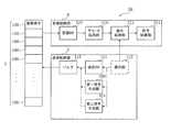
- FIG. 1 is a block diagram illustrating a configuration of the ultrasonic signal processing apparatus according to the first embodiment.
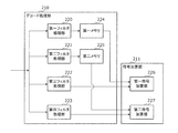
- FIG. 2 is a block diagram illustrating the decoding processing unit.
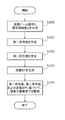
- FIG. 3 is a flowchart of transmission ultrasonic signal generation.
- FIG. 4 is a diagram illustrating the relationship between the code and the transmission aperture.
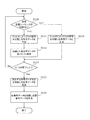
- FIG. 5 is a flowchart of a method for decoding a received ultrasonic signal.
- FIG. 6 is a block diagram illustrating a configuration of the ultrasonic signal processing apparatus according to the second embodiment.
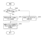
- FIG. 7 is a flowchart of the weight processing unit.
- FIG. 8 is a diagram illustrating an example of a vibration element array in which a plurality of vibration elements are arranged one-dimensionally.
- FIG. 9 is a diagram illustrating an example of a vibration element array in which a plurality of vibration elements are arranged two-dimensionally.
- FIG. 10 is a flowchart for explaining an ultrasonic signal processing method performed by the ultras
- the Golay code is a code sequence in which the sum of the aperiodic autocorrelation functions of two code sequences becomes 0 except for the 0 shift point.
- sequence S1 and the sequence S2 shown in (Equation 1) are two-phase (+, ⁇ ) Golay codes having the same length L, S1 and S2 satisfy the condition of (Equation 2).
- RS represents an autocorrelation function
- ⁇ represents a time shift
- an ultrasonic signal processing device includes a plurality of vibration elements, emits ultrasonic waves to a subject, and reflects the ultrasonic waves on the subject.
- An oscillating element array that receives the received echo
- a transmission control unit that generates an ultrasonic wave according to a signal encoded from the oscillating element array, and a signal that corresponds to the echo received at the oscillating element array
- the first code pattern and the third code pattern, and the second code pattern and the fourth code pattern are two orthogonal code pairs that satisfy the relationship of orthogonal codes, respectively.
- the transmission control unit further includes a first code string formed by arranging the first code pattern and the third code pattern, and a second code formed by arranging the second code pattern and the fourth code pattern.
- a first code generation unit that generates a first code set composed of a code string, a third code string in which one code pattern of the first code string is replaced with a pause code pattern, and the one of the second code string
- a second code generation unit that generates a second code set consisting of a code pattern of the second sequence and a fourth code string obtained by replacing the code pattern of the complementary sequence pair with a pause code pattern, and (i) among the plurality of vibration elements
- the first code string of the first code set is output to the one or more first vibrating elements at a first timing
- the second code string is output at a second timing after the first timing.
- the third code string of the second code set is output at the first timing to a plurality of second vibration elements arranged at positions sandwiching one or more first vibration elements, and the fourth code A pulser that generates the ultrasonic wave from the vibration element array by outputting a column at the second timing, and the reception control unit includes the echo received by the vibration element array,
- the first code string output at the first timing and the ultrasound corresponding to the third code string are reflected by the subject, and the second code string is output at the second timing.
- a first filter by a first filter for extracting one of the two complementary series pairs for each of the second echoes reflected by the subject with the ultrasonic wave corresponding to the fourth code string processing And a second filter process using a second filter for extracting the other of the two complementary series pairs, and a first filter process for each of the first echo and the second echo
- a code addition unit that adds the second results that are the results of the second filter processing for each of the first echo and the second echo.
- an ultrasonic wave with a small transmission aperture and an ultrasonic wave with a transmission aperture larger than the transmission aperture including at least the transmission aperture are included. Since both can be transmitted and both of the ultrasonic waves are easily separated, the inside of the subject can be accurately visualized in both the region on the near side and the region on the heel side from the focal position of the ultrasonic wave. .
- the transmission control unit may be configured as the first vibration element that does not vibrate the vibration element based on a predetermined F value for each of the plurality of vibration elements constituting the vibration element array. Either one of vibration and vibration as the second vibration element may be determined.
- an operation unit that receives an input related to a focal length from an operator is further provided, and the transmission control unit is received by the operation unit for each of the plurality of vibration elements constituting the vibration element array. Based on the position, any one of not vibrating, vibrating as the first vibrating element, and vibrating as the second vibrating element may be determined.
- a weight processing unit for multiplying the first weight corresponding to the first result and multiplying the second weight corresponding to the second result may be provided.
- the weight processing unit may determine the first weight and the second weight to be equal at the focal position based on a preset focal position.
- the weight processing unit is a result of the decoding process performed on an echo in which an ultrasonic wave having a code pattern included in the first code set and the second code set is reflected on the subject.
- one of the first weight and the second weight multiplied by one of the first result and the second result is multiplied by the first result and the second result.
- An area closer to the focal position than the other weight of the first weight and the second weight multiplied with respect to the other result of the second results is smaller than the focal position. You may determine so that it may become so large that the area
- the weight processing unit may determine the first weight and the second weight to be a constant value when they are added to each other regardless of the distance from the focal position.
- a recording medium recording medium such as a system, a method, an integrated circuit, a computer program or a computer-readable CD-ROM, and the system, method, integrated circuit, You may implement
- FIG. 1 is a block diagram illustrating a configuration of the ultrasonic signal processing apparatus according to the first embodiment.
- the ultrasonic signal processing apparatus 1 includes a vibration element array 2, a transmission control unit 3, and a reception control unit 4.
- the vibration element array 2 includes a plurality of vibration elements 100, emits ultrasonic waves to the subject, and receives echoes reflected by the ultrasonic waves on the subject.
- the transmission control unit 3 includes an operation unit 110, a transmission BF (Beam Former) 111, a pulsar 112, a first code generation unit 200, and a second code generation unit 201.
- the reception control unit 4 includes a reception BF (Beam Former) 120, a decoding processing unit 210, and a code addition unit 211.
- the vibration element array 2 includes a plurality of vibration elements 100, emits ultrasonic waves to the subject, and receives echoes that are reflected from the subject.
- the transmission control unit 3 generates an ultrasonic wave including a signal encoded from the vibration element array 2.
- the reception control unit 4 decodes a signal included in the echo received by the vibration element array 2.
- FIG. 2 is a block diagram illustrating the configuration of the decoding processing unit and the code addition unit of the first embodiment.
- the decode processing unit 210 includes a first filter processing unit 220, a second filter processing unit 221, a third filter processing unit 222, a fourth filter processing unit 223, a first memory 224, and a second memory 225.
- the code addition unit 211 includes a first code addition unit 226 and a second code addition unit 227.
- the operation unit 110 receives an input regarding the focal length from the operator.
- the operation unit 110 calculates a transmission beam signal, a first code signal, and a second code signal from the received operation signal.
- the operation unit 110 outputs the calculated transmission beam signal to the transmission BF 111, outputs the calculated first code signal to the first code generation unit 200, and outputs the calculated second code signal to the second code generation unit 201. .
- the transmission BF 111 calculates a transmission beam profile from the input transmission beam signal, and outputs the calculated transmission beam profile to the pulser 112.
- the first code generation unit 200 calculates a first code set from the input first code signal and outputs the first code set to the pulser 112.
- the second code generation unit 201 calculates a second code set from the input second code signal, and outputs the first code set to the pulser 112.
- the pulsar 112 is based on the transmission beam profile output from the transmission BF 111, the first code set generated by the first code generation unit 200, and the second code set generated by the second code generation unit 201.
- a drive signal for driving the plurality of vibration elements 100 of the vibration element array 2 is output to the plurality of vibration elements 100.
- the plurality of vibration elements 100 output ultrasonic waves based on the input drive signal into the subject.
- the plurality of vibration elements 100 receive echoes reflected in the subject according to the difference in acoustic impedance in the subject.
- the plurality of vibration elements 100 generate an RF (Radio Frequency) signal based on the received echo, and output the generated RF signal to the reception BF 120.
- RF Radio Frequency
- the reception BF 120 calculates a DAS (Delay and Sum) signal from the input RF signal, and outputs the calculated DAS signal to the decoding processing unit 210.
- DAS Delay and Sum
- the decoding processor 210 calculates first decoded data and second decoded data from the input DAS signal, and outputs the calculated first decoded data and second decoded data to the code adder 211.
- the code addition unit 211 calculates addition decoded data from the input first decoded data and second decoded data, and outputs the calculated addition decoded data.
- the first filter processing unit 220 calculates code data A from the input DAS signal, and outputs the calculated code data A to the first memory 224.
- the second filter processing unit 221 calculates code data B from the input DAS signal, and outputs the calculated code data B to the second memory 225.
- the third filter processing unit 222 calculates code data C from the input DAS signal, and outputs the calculated code data C to the first code addition unit 226.
- the fourth filter processing unit 223 calculates code data D from the input DAS signal, and outputs the calculated code data D to the second code adder 227.
- the first memory 224 stores the code data A until the timing at which the code data C is output by the third filter processing unit 222 to the first code addition unit 226, and the code data A is sent to the first code addition unit 226 at this timing. Output.
- the second memory 225 stores the code data B until the timing at which the code data D is output to the second code adder 227 by the fourth filter processing unit 223, and the code data D is sent to the second code adder 227 at this timing. Output.
- the first code adding unit 226 calculates first decoded data from the input code data A and code data C.
- the second code adder 227 calculates second decoded data from the input code data B and code data D.
- FIG. 3 is a flowchart showing transmission ultrasonic signal generation processing in the transmission control unit.
- the operation unit 110 When receiving a control signal from the operator, the operation unit 110 generates a transmission beam signal including at least the number of transmission vibration elements and a transmission aperture position, and a first code signal and a second code signal including at least a signal amplification amount (Ste S100).
- the “number of transmission vibration elements” indicates the number of vibration elements 100 driven by the control signal among the plurality of vibration elements 100.
- the “transmission aperture position” indicates the position of the vibration element 100 driven by the control signal.
- the “signal amplification amount” indicates the amplification amount of the ultrasonic signal assumed when the decoding process is performed.
- the first code generation unit 200 determines the code length (chip) and the code pattern from the signal amplification amount included in the first code signal, and is completely complementary.
- a first code set that is a code set that satisfies the sequence relationship is generated (step S101).
- a code set satisfying the relationship of a completely complementary sequence is an aperiodic cross-correlation between one sequence belonging to one Golay code sequence and one sequence belonging to the other Golay code sequence in two Golay code sequences.
- This is a code set in which the sum of the non-periodic cross-correlation function of the function and the other sequence belonging to one Golay code sequence and the other sequence belonging to the other Golay code sequence is 0 in all shifts.
- a complete complementary code set can be expressed by (Equation 3) if Golay code sequence ⁇ C1, C2 ⁇ and Golay code sequence ⁇ C3, C4 ⁇ .
- RC indicates a cross-correlation function
- the code pattern assumes all patterns satisfying the condition of (Equation 5)
- the first code set is the first code string G1 as shown in (Equation 5). It consists of the second code string G2.
- the first code generation unit 200 has the first code sequence G1 formed by arranging the first code pattern C1 and the third code pattern C3, and the second code pattern C2 and the fourth code pattern C4 arranged.
- a first code set consisting of the second code string G2 is generated.
- the first code pattern C1 and the second code pattern C2, and the third code pattern C3 and the fourth code pattern C4 are two complementary sequence pairs that satisfy the complementary sequence relationship.
- the first code pattern C1 and the third code pattern C3, and the second code pattern C2 and the fourth code pattern C4 are two orthogonal code pairs that satisfy the relationship of the orthogonal codes.
- the first code string G1 and the second code string G2 satisfy the relationship of a completely complementary sequence.
- the second code generation unit 201 determines a code length (chip) and a code pattern from the signal amplification amount included in the second code signal, A code set is generated (step S102).
- the second code set includes a third code string G3 and a fourth code string G4 as shown in (Equation 6).
- the third code sequence G3 and the fourth code sequence G4 are configured by one of the completely complementary code sets constituting the first code set and the pause code set, and can be expressed by (Equation 6).
- B represents the pause code pattern B and can be expressed by (Equation 7).
- the second code generation unit 201 includes the third code string G3 in which one code pattern (first code pattern C1) of the first code string G1 is replaced with the pause code pattern, and the one of the second code string G2.
- a second code set is generated which includes a code pattern (first code pattern C1) and a fourth code string G4 in which a code pattern (second code pattern C2) which is a complementary sequence pair is replaced with a pause code pattern.
- the pause code pattern is a code indicating a state in which no code is transmitted, and is 0, for example, as in (Equation 7).
- transmission BF 111 receives the transmission beam signal from the operation unit 110, at least the first vibration element number TA 1, the second vibration element number TA 2, the first transmission opening position 300, and the second transmission beam signal are received from the transmission beam signal.
- a transmission beam profile (hereinafter referred to as “transmission BP”) including the transmission aperture position 301 and the delay profile is calculated (step S103).
- the “first vibration element number TA1” indicates the number of vibration elements to be driven based on the first code set when transmitting ultrasonic waves to the subject
- the “second vibration element number TA2” is the second number.
- the number of vibration elements to be driven based on the code set is shown.
- the first vibration element number TA1 and the second vibration element number TA2 satisfy the condition of (Equation 8).
- FIG. 4 is a diagram for explaining the first transmission opening position 300 and the second transmission opening position 301 in the vibration element array in the ultrasonic probe.
- the first transmission opening position 300 indicates a predetermined position of one or more vibration elements that are driven based on the first code set among the plurality of vibration elements 100 of the vibration element array 2.
- the second transmission opening position 301 indicates a predetermined position of a plurality of vibration elements that are driven based on the second code set among the plurality of vibration elements 100 of the vibration element array 2.
- the first transmission opening position 300 is located at a position sandwiched between the second transmission opening positions 301. That is, the first transmission opening position 300 is surrounded by the second transmission opening position 301 and is the center of the plurality of vibration elements 100 configuring the vibration element array 2.
- the second transmission opening position 301 surrounds the first transmission opening position 300 and is an end of the plurality of vibration elements 100 constituting the vibration element array 2.
- the second transmission opening position 301 is separated at one or more points.
- the delay profile is calculated from the focal position 302 based on the region of interest that the operator wants to draw.
- steps S101 to S103 are processed in series so that step S102 is performed after step S101 and step S103 is performed after step S102, but they may be processed simultaneously in parallel after step S100.
- the pulser 112 uses the first code set generated by the first code generation unit 200, the second code set generated by the second code generation unit 201, and the transmission BP generated by the transmission BF111.
- the drive signal is generated, and the plurality of vibration elements 100 are driven based on the generated drive signal (step S104). More specifically, the pulsar 112 is connected to one or more first vibration elements (that is, vibration elements at the first transmission opening position 300) of the plurality of vibration elements 100 of the vibration element array 2 by the first code set.
- the first code string G1 is output at the first timing
- the second code string G2 is output at the second timing after the first timing.
- the pulser 112 further adds a third code string to a plurality of second vibration elements (that is, vibration elements at the second transmission opening position 301) arranged at positions where the first vibration element among the plurality of vibration elements 100 is sandwiched. G3 is output at the first timing, and the fourth code string G4 is output at the second timing.
- the pulser 112 outputs the first code string G1 and the third code string G3 at the first timing, and outputs the second code string G2 and the fourth code string G4 at the second timing, Ultrasonic waves are generated from the vibration element array 2.
- FIG. 5 is a flowchart showing a decoding process of the received ultrasonic signal in the reception control unit.
- the decoding processing unit 210 determines the code transmission sequence I (step S110).
- the decoding processing unit 210 performs the process of step S111.
- the decode processing unit 210 performs the process of step S112.
- the “code transmission sequence” is one or more transmission / reception times required for decoding, and transmission / reception is performed continuously or at an arbitrary interval.
- each of the first filter processing unit 220 and the second filter processing unit 221 receives the DAS signal from the reception BF120. Then, a predetermined filter process is performed on the DAS signal (step S111). As a result, the DAS signal is separated into code data A and code data B.
- the filter A used for the first filter processing performed by the first filter processing unit 220 is FA
- the filter B used for the second filter processing performed by the second filter processing unit 221 is FB
- FA and FB are represented by (Formula 9).
- the filter A and the filter B are called matched filters, and are configured by codes in which the order of the elements of the Golay code sequences C1 and C3 are reversed.
- code data A is DG A
- code data B is DG B
- DG A and DG B are expressed by (Equation 10).
- DS indicates DAS signal data
- symbol * indicates convolution
- the first memory 224 receives the code data A from the first filter processing unit 220
- the second memory 225 receives the code data B from the second filter processing unit 221, and stores the data in each memory space until a predetermined timing.
- the “predetermined timing” is a timing at which the code data A and the code data B are transferred from the first memory 224 and the second memory 225 to the first code adder 226 and the second code adder 227, respectively. Yes, specifically, the timing when step S113 ends.
- each of the third filter processing unit 222 and the fourth filter processing unit 223 receives the DAS signal from the reception BF120. Then, a predetermined filter process is performed on the DAS signal (step S113). As a result, the DAS signal is separated into code data C and code data D.
- FC and FD are expressed by (Formula 11).
- the filter C and the filter D are called matched filters, and are configured by codes in which the order of the elements of the Golay code sequences C2 and C4 are reversed.
- the code data C is DG C
- the code data D is DG D
- DG C and DG D are expressed by (Equation 12).
- the decoding processing unit 210 outputs the first ultrasonic wave corresponding to the first code string G1 and the third code string G3 output at the first timing out of the echoes received by the reception BF 120 and reflected by the subject.
- First filter processing for extracting one of Golay code sequence ⁇ C1, C2 ⁇ and Golay code sequence ⁇ C3, C4 ⁇ (here, Golay code sequence ⁇ C1, C2 ⁇ ) and Golay code sequence ⁇ C1 , C2 ⁇ and the other Golay code sequence ⁇ C3, C4 ⁇ (here, Golay code sequence ⁇ C3, C4 ⁇ ) is extracted.
- a filter process using the filter A and the filter C is performed.
- the filter process using the filter B and the filter D is performed as the second filter process for extracting the Golay code sequence ⁇ C3, C4 ⁇ . If the filter processing using the filter A is performed, the signal including the code pattern C1 is decoded, and the signal including the code pattern C3 is canceled. If the filter process using the filter B is performed, the signal including the code pattern C1 is canceled, and the signal including the code pattern C3 is decoded. If the filter process using the filter C is performed, the signal including the code pattern C2 is decoded, and the signal including the code pattern C4 is canceled.
- the filter process using the filter D is performed, the signal including the code pattern C2 is canceled and the signal including the code pattern C4 is decoded. That is, the first filter process can be said to be a process for canceling the Golay code sequence ⁇ C3, C4 ⁇ .
- the second filter process can also be said to be a process for canceling the Golay code sequence ⁇ C1, C2 ⁇ .
- the code pattern C1 and the code pattern C3 are orthogonal code pairs
- the code pattern C2 and the code pattern C4 are orthogonal code pairs.
- the code pattern C1 and the code pattern C3 can be separated from the signal including the code pattern C1 and the code pattern C3, respectively.
- the code pattern C2 and the code pattern C4 can be separated from the signal including the code pattern C2 and the code pattern C4, respectively.
- the code adding unit 211 calculates first decoded data DG1 and second decoded data DG2 from the code data A to D (step S115). Specifically, the first code adding unit 226 receives the code data C that is the processing result of the third filter processing unit 222 and the code data A held in the first memory 224, and receives the code data A and the code data. First decoded data DG1 is calculated from C. Further, the second code adding unit 227 receives the code data D that is the processing result of the fourth filter processing unit 223 and the code data B held in the second memory 225, and receives the code data B and the code data D from the code data B and the code data D. Second decoded data DG2 is calculated. Here, the first decoded data DG1 and the second decoded data DG2 are expressed by (Equation 13).
- the code addition unit 211 adds the first results (that is, the code data A and the code data C) that are the results of the first filter processing for each of the first echo and the second echo, and the first echo
- the second results that is, the code data B and the code data D
- the code data B and the code data D that are the results of the second filter processing for each of the second echoes are added.
- the code addition unit 211 receives the first decoded data DG1 added by the first code addition unit 226 and the second decoded data DG2 added by the second code addition unit 227, the code addition unit 211 receives the first decoded data DG1 and The additional decoded data DGS is calculated by further adding the second decoded data DG2 (step S116).
- the addition decoded data DGS is expressed by (Equation 14).
- the ultrasonic signal processing apparatus 1 includes, in one transmission of an ultrasonic wave using a pair in a complementary series relationship, the transmission including at least the ultrasonic wave with a small transmission aperture and the transmission aperture. Since both of the ultrasonic waves from the transmission aperture larger than the aperture can be transmitted and both ultrasonic waves are easily separated, the subject's object in both the near side and the far side from the focal point of the ultrasonic wave Internal visualization can be performed with high accuracy.
- the first code set is described as (Equation 6), but the first code set is not limited to this, and the first transmission code is configured by reversing the order of the codes or by nesting the codes. Or you may.
- the second code set has been described as (Equation 7), but the present invention is not limited to this, and the second transmission code may be configured by reversing the order of the codes, or may be configured by nesting the codes. May be.
- the second vibration element number TA2 may be calculated using (Equation 15).
- id indicates the image quality improvement position 303 in FIG. 4, and F indicates the F value.
- the image quality improvement position 303 may be arbitrarily set by the operator, or may be a position specified by reading a value preset in the ultrasonic signal processing apparatus.
- the image quality improvement position 303 is a position where the improvement effect of the azimuth resolution is to be emphasized, and is set on the near side from the focal position 302.
- the transmission control unit 3 causes each of the plurality of vibration elements 100 constituting the vibration element array 2 to vibrate the vibration element 100 as a first vibration element that does not vibrate based on a predetermined F value. And any one of vibrating as the second vibration element may be determined.
- the transmission control unit 3 serves as a first vibration element that does not vibrate the vibration element 100 based on the position received by the operation unit 110 for each of the plurality of vibration elements 100 constituting the vibration element array 2. Either one of vibration and vibration as the second vibration element may be determined.
- FIG. 6 is a block diagram illustrating a configuration of the ultrasonic signal processing apparatus according to the second embodiment.
- the ultrasonic signal processing device 1a includes a weight processing unit 212 in addition to the configuration of the first embodiment.
- the weight processing unit 212 based on the first decoded data and the second decoded data calculated by the decoding processing unit 210, and the weight control signal and weight setting signal input by the operation unit 110, Second weight decoded data is calculated and output to the code adding unit 211. That is, the weight processing unit 212 multiplies the first weight corresponding to the first result set (that is, the code data A and the code data C), and the second result set (that is, the code data B and the code data). Multiply by a second weight corresponding to data D).
- the “weight control signal” is information for determining a first weight vector WM1 (WA1) as a first weight and a second weight vector WM2 (WA2) as a second weight, which will be described later. It is a signal to show.
- the “weight setting signal” is a signal indicating whether the operator has selected a method for controlling a weight vector or whether the operator has selected a method for using a weight stored in advance in the apparatus.
- FIG. 7 is a flowchart showing the generation processing of the first weight decoded data and the second weight composite data in the weight processing unit.
- step S201 when the operation unit 110 accepts an input indicating that the operator changes the weight vector by performing input to the operation unit 110, the process proceeds to step S201.
- step S201 when the operation unit 110 receives an input indicating that the weight stored in advance in the apparatus is read and used, the process proceeds to step S202.
- the weight processing unit 212 determines a predetermined value from the weight control signal received from the operation unit 110.
- First weight vector WM1 and second weight vector WM2 are calculated (step S201).
- the first weight vector WM1 and the second weight vector WM2 are expressed by (Equation 16).
- N indicates the number of data in the depth direction of the first decoded data and the second decoded data calculated by the decoding processing unit 210.
- the predetermined first weight vector WM1 and the second weight vector WM2 are obtained by using a dial type device, a slide type device, a button type device, a touch display type device, etc., in which the operator is a physical user interface.
- An arbitrary value is set for each value or a plurality of values of the first weight vector WM1 and the second weight vector WM2.
- the first weight vector WM1 and the second weight vector WM2 may be set using a software graphical user interface.
- the weight processing unit 212 receives the value from the operation unit 110.
- a predetermined first weight vector WA1 and second weight vector WA2 are determined from the weight control signal (step S202). In this case, the first weight vector signal WA1 and the second weight vector signal WA2 are expressed by (Equation 17).
- N indicates the number of data in the depth direction of the first decoded data and the second decoded data calculated by the decoding processing unit 210.
- the predetermined first weight vector WA1 and the predetermined second weight vector WA2 can be designed using fd indicating the focal position 302.
- the first weight vector signal WA1 is expressed by (Equation 18).
- w 1 represents the first weight amount
- a 1 represents the first weight change amount.
- the second weight vector signal WA2 is expressed by (Equation 19).
- each weight vector signal may be designed such that the result of adding the values of the first weight vector WA1 and the second weight vector WA2 is constant.
- the first weight amount w 1 and the second weight vector The weight amount w 2 , the first weight change amount a 1, and the second weight change amount a 2 satisfy the condition of (Equation 20).
- the first weight vector WA1 and the second weight vector WA2 can be calculated from (Expression 21).
- the weight processing unit 212 may determine the first weight and the second weight to be equal at the focal position 302 based on the preset focal position 302. Further, as shown in (Equation 18), (Equation 19), and (Equation 21), the weight processing unit 212 uses the ultrasonic waves generated by the code patterns C3 and C4 that are commonly included in the first code set and the second code set. Is the result of the decoding process performed on the echo reflected from the subject, and is multiplied by one of the first result and the second result (here, the second result DG2). One weight vector (here, the second weight vector WA2) of the vector WA1 and the second weight vector WA2 is set to the other result (here, the first result DG1) of the first result and the second result.
- the second weight vector WA2 One weight vector (here, the second weight vector WA2) of the vector WA1 and the second weight vector WA2 is set to the other result (here, the first result DG1) of the first result and the second result.
- the region closer to the focal point 302 than the other weight vector (here, the first weight vector WA1) of the first weight vector WA1 and the second weight vector WA2 to be multiplied. Fence, may be determined to be larger as the area of ⁇ than the focal position 302. Further, as shown in (Equation 20), the weight processing unit 212 has a constant value when the first weight vector WA1 and the second weight vector WA2 are added to each other regardless of the distance from the focal position 302. You may decide to.
- the weight processing unit 212 calculates the first weight decoded data DGW1 and the second weight decoded data DGW2 (step S203). More specifically, the weight processing unit 212 calculates the first weight decoded data DGW1 from the first decoded data DG1 and the first weight vector WM1 (WA1), and the second decoded data DG2 and the second weight vector WM1 ( Second weight decoded data DGW2 is calculated from WA2).
- the first weight decoded data DGW1 and the second weight decoded data DGW2 can be expressed by (Expression 22) or (Expression 23).
- the ultrasonic signal processing device 1a can generate the first weight decoded data DGW1 and the second weight decoded data DGW2 obtained by multiplying a predetermined weight vector in the depth direction. For this reason, the first decoded data DG1 with high accuracy in the shallow portion can be emphasized in the shallow portion closer to the focal position 302, and the second decoding with high accuracy in the deep portion in the deep portion on the heel side than the focal position 302. Data DG2 can be highlighted.
- the first weight vector WA1 and the second weight vector WA2 have been described as (Equation 18) and (Equation 19).
- the first weight vector WA1 and the second weight vector WA2 are not limited to these.
- it may be expressed by a linear function that can be conceived by the person concerned.
- the first weight vector WA1 and the second weight vector WA2 may be generated using not only a linear function but also a non-linear function.
- first weight vector WA1 and the second weight WA2 are calculated from fd indicating the focal position 302, id indicating the image quality improvement position 303 may be used instead of fd indicating the focal position 302.
- the specific configuration of the vibration element array 2 is not mentioned, but for example, a plurality of one-dimensionally as shown in FIG.
- vibration elements 100 When a plurality of vibration elements 100 are arranged one-dimensionally as shown in FIG. 8, for example, five vibration elements 100 arranged in the center are set as the first vibration elements arranged in the first transmission opening position, and the first vibration element 100 is arranged. Six vibration elements sandwiched between three vibration elements from both sides around the element may be set as the second vibration elements arranged in the second transmission opening position.
- the vibration elements arranged at the center among the plurality of vibration elements 100. 100 is set as the first vibration element arranged at the first transmission opening position, and the vibration element 100 arranged around the first vibration element is set as the second vibration element arranged at the second transmission opening position. Good.
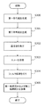
- FIG. 10 is a flowchart for explaining an ultrasonic signal processing method performed by the ultrasonic signal processing apparatus.
- the first code generation unit 200 arranges the first code sequence G1 formed by arranging the first code pattern C1 and the third code pattern C3, and the second code pattern C2 and the fourth code pattern C4.
- a first code set consisting of the second code string G2 is generated (step S300: first code generation step).
- the second code generation unit 201 includes a third code string G3 in which one code pattern (first code pattern C1) of the first code string G1 is replaced with a pause code pattern, and the one of the second code strings G2.
- the second code set is generated by the fourth code string G4 in which the code pattern (first code pattern C1) and the code pattern (second code pattern C2) which is a complementary sequence pair are replaced with a pause code pattern (step S301). : Second code generation step).
- the pulser 112 outputs (i) the first code string G1 of the first code group to the one or more first vibration elements of the plurality of vibration elements 100 at the first timing, and
- the second code sequence G2 is output at a second timing after the first timing, and
- a third code sequence is provided to a plurality of second vibration elements arranged at positions sandwiching one or more first vibration elements.
- the vibration element array 2 receives an echo in which the ultrasonic wave generated by the vibration element array 2 is reflected by the subject (step S303: reception step).
- First filter processing by the filters (filter A and filter C) and second filter processing by the second filter for extracting the other of the two complementary series pairs are performed (S304: decoding processing step).
- each component may be configured by dedicated hardware or may be realized by executing a software program suitable for each component.
- Each component may be realized by a program execution unit such as a CPU or a processor reading and executing a software program recorded on a recording medium such as a hard disk or a semiconductor memory.
- the software that realizes the ultrasonic signal processing apparatus according to each of the above-described embodiments is the following program.
- this program has a plurality of vibration elements in a computer, emits an ultrasonic wave to a subject, and receives an echo reflected by the subject, and the vibration element array
- An ultrasonic signal processing method in an ultrasonic signal processing apparatus comprising: a transmission control unit that generates ultrasonic waves from a transmission control unit; and a reception control unit that processes echoes received in the vibration element array, wherein: The code pattern and the second code pattern, and the third code pattern and the fourth code pattern are two complementary sequence pairs that satisfy the relationship of complementary sequences, respectively, and (ii) the first code pattern and the third code pattern When the code pattern, the second code pattern, and the fourth code pattern are two orthogonal code pairs that satisfy the relationship of the orthogonal codes, respectively, Generates a first code set consisting of a first code string formed by arranging the code pattern and the third code pattern and a second code string formed by arranging the second code pattern and the fourth code pattern A first code generation step, a third code string in which one code pattern of the first
- a part or all of the components constituting each of the above devices may be configured by one system LSI (Large Scale Integration).
- the system LSI is an ultra-multifunctional LSI manufactured by integrating a plurality of components on a single chip, and specifically, a computer system including a microprocessor, ROM, RAM, and the like. .
- the RAM stores a computer program that achieves the same operation as each of the above devices.
- the system LSI achieves its functions by the microprocessor operating according to the computer program.
- the present invention is not limited to LSI, and may be realized by a dedicated circuit or a general-purpose processor.
- An FPGA Field Programmable Gate Array
- reconfigurable processor that can reconfigure the connection and setting of circuit cells inside the LSI may be used.
- a part or all of the constituent elements constituting each of the above devices may be constituted by an IC card or a single module that can be attached to and detached from each device.
- the IC card or the module is a computer system including a microprocessor, a ROM, a RAM, and the like.
- the IC card or the module may include the super multifunctional LSI described above.
- the IC card or the module achieves its function by the microprocessor operating according to the computer program. This IC card or this module may have tamper resistance.
- the present invention may be a method realized by the computer processing described above.
- the present invention may be a computer program that is realized by a processor such as a CPU executing these methods, or may be a digital signal composed of the computer program.
- the computer program or the digital signal may be recorded on a computer-readable recording medium.
- the computer-readable recording medium include a flexible disk, a hard disk, a CD-ROM, an MO, a DVD, a DVD-ROM, a DVD-RAM, a BD (Blu-ray (registered trademark) Disc), and a semiconductor memory.
- the present invention may be the digital signal recorded on these recording media.
- the computer program or the digital signal may be transmitted via an electric communication line, a wireless or wired communication line, a network represented by the Internet, a data broadcast, or the like.
- the present invention may also be a computer system including a microprocessor and a memory.
- the memory may store the computer program, and the microprocessor may operate according to the computer program.
- the program or the digital signal is recorded on the recording medium and transferred, or the program or the digital signal is transferred via the network or the like, and executed by another independent computer system. It is good.
- division of functional blocks in the block diagram is an example, and a plurality of functional blocks can be realized as one functional block, a single functional block can be divided into a plurality of functions, or some functions can be transferred to other functional blocks. May be.
- functions of a plurality of functional blocks having similar functions may be processed in parallel or time-division by a single hardware or software.
- the present invention is useful as an ultrasonic signal processing apparatus and an ultrasonic signal processing method that can improve the trade-off relationship between the resolution of shallow portions and the sensitivity of deep portions in the generation of ultrasonic images.
Landscapes
- Physics & Mathematics (AREA)
- Engineering & Computer Science (AREA)
- Radar, Positioning & Navigation (AREA)
- Remote Sensing (AREA)
- Acoustics & Sound (AREA)
- Computer Networks & Wireless Communication (AREA)
- General Physics & Mathematics (AREA)
- Ultra Sonic Daignosis Equipment (AREA)
Description
本発明者は、「背景技術」の欄において記載した、システムに関し、以下の問題が生じることを見出した。


図1は、実施の形態1の超音波信号処理装置の構成を示すブロック図である。












図6は、実施の形態2の超音波信号処理装置の構成を示すブロック図である。以下、実施の形態1の超音波信号処理装置1と同様の構成については、同じ符号を用い、説明を省略する。超音波信号処理装置1aは、実施の形態1の構成に加えて重み処理部212を備える。





(1)
上記実施の形態1および2に係る超音波信号処理装置1、1aでは、振動素子アレイ2の具体的な構成については言及していないが、例えば、図8に示すような、一次元的に複数の振動素子100が並ぶ振動素子アレイ20としてもよいし、図9に示すような、二次元的に複数の振動素子100が並ぶ振動素子アレイ21としてもよい。
また、上記実施の形態1および2に係る超音波信号処理装置1、1aでは、送信制御部3で行われる処理と、受信制御部4で行われる処理とに分けて説明しているが、これに限らずに、図10に示すように、1つの処理フローで行われてもよい。図10は、超音波信号処理装置によって行われる超音波信号処理方法を説明するためのフローチャートである。
また、上記各実施の形態において、各構成要素は、専用のハードウェアで構成されるか、各構成要素に適したソフトウェアプログラムを実行することによって実現されてもよい。各構成要素は、CPUまたはプロセッサなどのプログラム実行部が、ハードディスクまたは半導体メモリなどの記録媒体に記録されたソフトウェアプログラムを読み出して実行することによって実現されてもよい。ここで、上記各実施の形態の超音波信号処理装置などを実現するソフトウェアは、次のようなプログラムである。
なお、本発明を上記実施の形態に基づいて説明してきたが、本発明は、上記の実施の形態に限定されず、以下のような場合も本発明に含まれる。
2、20、21 振動素子アレイ
3 送信制御部
4 受信制御部
100 振動素子
110 操作部
111 送信BF
112 パルサ
120 受信BF
200 第一符号生成部
201 第二符号生成部
210 デコード処理部
211 符号加算部
212 重み処理部
220 第一フィルタ処理部
221 第二フィルタ処理部
222 第三フィルタ処理部
223 第四フィルタ処理部
224 第一メモリ
225 第二メモリ
226 第一符号加算部
227 第二符号加算部
300 第一送信開口位置
301 第二送信開口位置
302 焦点位置
303 画質改善位置
C1 第一符号パタン
C2 第二符号パタン
C3 第三符号パタン
C4 第四符号パタン
G1 第一符号列
G2 第二符号列
G3 第三符号列
G4 第四符号列
Claims (9)
- [規則91に基づく訂正 27.11.2013]
複数の振動素子を有し、超音波を被検体に発すると共に、当該超音波が前記被検体において反射されたエコーを受信する振動素子アレイと、
前記振動素子アレイから符号化された信号に応じた超音波を発生させる送信制御部と、
前記振動素子アレイにおいて受信されたエコーに応じた信号を復号する受信制御部と、を備え、
(i)第一符号パタンおよび第二符号パタンと、第三符号パタンおよび第四符号パタンとがそれぞれ相補系列の関係を満たす2組の相補系列ペアであり、かつ、(ii)前記第一符号パタンおよび前記第三符号パタンと、前記第二符号パタンおよび前記第四符号パタンとがそれぞれ直交符号の関係を満たす2組の直交符号ペアである場合に、
前記送信制御部は、
前記第一符号パタンおよび前記第三符号パタンとが並ぶことによりなる第一符号列と、前記第二符号パタンおよび前記第四符号パタンとが並ぶことによりなる第二符号列とによりなる第一符号組を生成する第一符号生成部と、
前記第一符号列の一方の符号パタンを休止符号パタンに置き換えた第三符号列と、前記第二符号列のうち、第一符号列で休止符号パタンに置き換えた符号パタンと相補系列ペアである符号パタンを休止符号パタンに置き換えた第四符号列とによりなる第二符号組を生成する第二符号生成部と、
(i)前記複数の振動素子のうちの1以上の第一振動素子に、前記第一符号組のうちの前記第一符号列を第一タイミングで出力し、かつ、前記第二符号列を前記第一タイミングよりも後の第二タイミングで出力し、かつ、(ii)前記1以上の第一振動素子を挟み込む位置に配置される複数の第二振動素子に、前記第二符号組のうちの前記第三符号列を前記第一タイミングで出力し、かつ、前記第四符号列を前記第二タイミングで出力することで、前記振動素子アレイから前記超音波を発生させるパルサと、を有し、
前記受信制御部は、
前記振動素子アレイにより受信された前記エコーのうちの、前記第一タイミングで出力された前記第一符号列および前記第三符号列に応じた超音波が前記被検体において反射された第一エコーと、前記第二タイミングで出力された前記第二符号列および前記第四符号列に応じた超音波が前記被検体において反射された第二エコーとのそれぞれに対して、前記2組の相補系列ペアの一方を抽出するための第一フィルタによる第一フィルタ処理と、前記2組の相補系列ペアの他方を抽出するための第二フィルタによる第二フィルタ処理と、を行うデコード処理部と、
前記第一エコーおよび前記第二エコーのそれぞれに対する前記第一フィルタ処理の結果である第一結果同士を加算し、かつ、前記第一エコーおよび前記第二エコーのそれぞれに対する前記第二フィルタ処理の結果である第二結果同士を加算する符号加算部と、を有する
超音波信号処理装置。 - 前記送信制御部は、前記振動素子アレイを構成する前記複数の振動素子のそれぞれについて、予め定められたF値に基づいて、当該振動素子を、振動させない、前記第一振動素子として振動させる、および、前記第二振動素子として振動させる、のいずれか1つを決定する
請求項1に記載の超音波信号処理装置。 - さらに、
操作者からの焦点距離に関する入力を受け付ける操作部を備え、
前記送信制御部は、前記振動素子アレイを構成する前記複数の振動素子のそれぞれについて、前記操作部により受け付けられた位置に基づいて、当該振動素子を、振動させない、前記第一振動素子として振動させる、および、前記第二振動素子として振動させる、のいずれか1つを決定する
請求項1に記載の超音波信号処理装置。 - さらに、
前記第一結果に対応する第一の重みを乗算し、かつ、前記第二結果に対応する第二の重みを乗算する重み処理部を備える
請求項1から3のいずれか1項に記載の超音波信号処理装置。 - 前記重み処理部は、前記第一の重みおよび前記第二の重みを、予め設定されている焦点位置に基づいて、前記焦点位置において等しくなるように決定する
請求項4に記載の超音波信号処理装置。 - 前記重み処理部は、前記第一符号組および前記第二符号組に共通して含まれる符号パタンによる超音波が前記被検体において反射されたエコーに対する前記デコード処理が行われた結果であって、前記第一結果および前記第二結果のうちの一方の結果に対して乗算される前記第一の重みおよび前記第二の重みのうちの一方の重みを、前記第一結果および前記第二結果のうちの他方の結果に対して乗算される前記第一の重みおよび前記第二の重みのうちの他方の重みよりも、前記焦点位置より手前側の領域ほど小さく、前記焦点位置より奧側の領域ほど大きくなるように決定する
請求項5に記載の超音波信号処理装置。 - 前記重み処理部は、前記焦点位置からの距離にかかわらず、前記第一の重みおよび前記第二の重みを、互いに加算したときに一定値になるように決定する
請求項4から6のいずれか1項に記載の超音波信号処理装置。 - [規則91に基づく訂正 27.11.2013]
複数の振動素子を有し、超音波を被検体に発すると共に、当該超音波が前記被検体において反射されたエコーを受信する振動素子アレイと、
前記振動素子アレイから超音波を発生させる送信制御部と、
前記振動素子アレイにおいて受信されたエコーを処理する受信制御部と、を備える超音波信号処理装置における超音波信号処理方法であって、
(i)第一符号パタンおよび第二符号パタンと、第三符号パタンおよび第四符号パタンとがそれぞれ相補系列の関係を満たす2組の相補系列ペアであり、かつ、(ii)前記第一符号パタンおよび前記第三符号パタンと、前記第二符号パタンおよび前記第四符号パタンとがそれぞれ直交符号の関係を満たす2組の直交符号ペアである場合に、
前記第一符号パタンおよび前記第三符号パタンとが並ぶことによりなる第一符号列と、前記第二符号パタンおよび前記第四符号パタンとが並ぶことによりなる第二符号列とによりなる第一符号組を生成する第一符号生成ステップと、
前記第一符号列の一方の符号パタンを休止符号パタンに置き換えた第三符号列と、前記第二符号列のうち、第一符号列で休止符号パタンに置き換えた符号パタンと相補系列ペアである符号パタンを休止符号パタンに置き換えた第四符号列とによりなる第二符号組を生成する第二符号生成ステップと、
(i)前記複数の振動素子のうちの1以上の第一振動素子に、前記第一符号組のうちの前記第一符号列を第一タイミングで出力し、かつ、前記第二符号列を前記第一タイミングよりも後の第二タイミングで出力し、かつ、(ii)前記第一振動素子を挟み込む位置に配置される複数の第二振動素子に、前記第二符号組のうちの前記第三符号列を前記第一タイミングで出力し、かつ、前記第四符号列を前記第二タイミングで出力することで、前記振動素子アレイから前記超音波を発生させる超音波発生ステップと、
前記振動素子アレイが前記エコーを受信する受信ステップと、
前記振動素子アレイにより受信された前記エコーのうちの、前記第一タイミングで出力された前記第一符号列および前記第三符号列に応じた超音波が前記被検体において反射された第一エコーと、前記第二タイミングで出力された前記第二符号列および前記第四符号列に応じた超音波が前記被検体において反射された第二エコーのそれぞれに対して、前記2組の相補系列ペアの一方を抽出するための第一フィルタによる第一フィルタ処理と、前記2組の相補系列ペアの他方を抽出するための第二フィルタによる第二フィルタ処理と、を行うデコード処理ステップと、
前記第一エコーおよび前記第二エコーのそれぞれに対する前記第一フィルタ処理の結果である第一結果同士を加算し、かつ、前記第一エコーおよび前記第二エコーのそれぞれに対する前記第二フィルタ処理の結果である第二結果同士を加算する信号加算ステップと、を含む
超音波信号処理方法。 - 請求項8に記載の超音波信号処理方法をコンピュータに実行させるためのプログラム。
Priority Applications (2)
| Application Number | Priority Date | Filing Date | Title |
|---|---|---|---|
| JP2014540741A JPWO2014057658A1 (ja) | 2012-10-12 | 2013-10-08 | 超音波信号処理装置、超音波信号処理方法、およびプログラム |
| US14/432,897 US20150260842A1 (en) | 2012-10-12 | 2013-10-08 | Ultrasonic signal processing apparatus, ultrasonic signal processing method, and program |
Applications Claiming Priority (2)
| Application Number | Priority Date | Filing Date | Title |
|---|---|---|---|
| JP2012226575 | 2012-10-12 | ||
| JP2012-226575 | 2012-10-12 |
Publications (1)
| Publication Number | Publication Date |
|---|---|
| WO2014057658A1 true WO2014057658A1 (ja) | 2014-04-17 |
Family
ID=50477140
Family Applications (1)
| Application Number | Title | Priority Date | Filing Date |
|---|---|---|---|
| PCT/JP2013/005989 Ceased WO2014057658A1 (ja) | 2012-10-12 | 2013-10-08 | 超音波信号処理装置、超音波信号処理方法、およびプログラム |
Country Status (3)
| Country | Link |
|---|---|
| US (1) | US20150260842A1 (ja) |
| JP (1) | JPWO2014057658A1 (ja) |
| WO (1) | WO2014057658A1 (ja) |
Cited By (2)
| Publication number | Priority date | Publication date | Assignee | Title |
|---|---|---|---|---|
| WO2015198824A1 (ja) * | 2014-06-26 | 2015-12-30 | 日立アロカメディカル株式会社 | 超音波撮像装置 |
| WO2017022540A1 (ja) * | 2015-08-06 | 2017-02-09 | 株式会社日立製作所 | 超音波撮像装置および超音波撮像方法 |
Families Citing this family (2)
| Publication number | Priority date | Publication date | Assignee | Title |
|---|---|---|---|---|
| US10852169B2 (en) * | 2014-09-21 | 2020-12-01 | Transus Instruments Pty Ltd | Ultrasonic flowmeter and method of controlling an ultrasonic flowmeter by simultaneously driving a pair of transducers without correlation |
| JP7828222B2 (ja) * | 2022-04-07 | 2026-03-11 | 富士フイルム株式会社 | 超音波診断装置及びビーム形成方法 |
Citations (3)
| Publication number | Priority date | Publication date | Assignee | Title |
|---|---|---|---|---|
| JP2000041980A (ja) * | 1998-04-20 | 2000-02-15 | General Electric Co <Ge> | 超音波散乱体をイメ―ジングするためのシステム及び方法 |
| JP2000060850A (ja) * | 1998-08-21 | 2000-02-29 | Aloka Co Ltd | 超音波診断装置 |
| JP2003010181A (ja) * | 2001-04-25 | 2003-01-14 | Medison Co Ltd | 直交ゴレーコードを用いる超音波撮像方法及びその装置 |
Family Cites Families (4)
| Publication number | Priority date | Publication date | Assignee | Title |
|---|---|---|---|---|
| KR100488431B1 (ko) * | 2003-01-24 | 2005-05-11 | 전자부품연구원 | 정 진폭 이진직교 변조 및 복조장치 |
| US7388899B2 (en) * | 2003-03-10 | 2008-06-17 | Texas Instruments Incorporated | Spreading code structure for ultra wide band communications |
| JP4521633B2 (ja) * | 2004-03-12 | 2010-08-11 | 直樹 末広 | 符号分割多重信号の相関分離識別方式 |
| DE102011075650B4 (de) * | 2011-05-11 | 2013-07-11 | Reinhart Rudershausen | Verfahren und Decodierer zum Entspreizen von Datensignalen, die mit Walsh-Sequenzen gespreizt sind |
-
2013
- 2013-10-08 US US14/432,897 patent/US20150260842A1/en not_active Abandoned
- 2013-10-08 JP JP2014540741A patent/JPWO2014057658A1/ja active Pending
- 2013-10-08 WO PCT/JP2013/005989 patent/WO2014057658A1/ja not_active Ceased
Patent Citations (3)
| Publication number | Priority date | Publication date | Assignee | Title |
|---|---|---|---|---|
| JP2000041980A (ja) * | 1998-04-20 | 2000-02-15 | General Electric Co <Ge> | 超音波散乱体をイメ―ジングするためのシステム及び方法 |
| JP2000060850A (ja) * | 1998-08-21 | 2000-02-29 | Aloka Co Ltd | 超音波診断装置 |
| JP2003010181A (ja) * | 2001-04-25 | 2003-01-14 | Medison Co Ltd | 直交ゴレーコードを用いる超音波撮像方法及びその装置 |
Cited By (4)
| Publication number | Priority date | Publication date | Assignee | Title |
|---|---|---|---|---|
| WO2015198824A1 (ja) * | 2014-06-26 | 2015-12-30 | 日立アロカメディカル株式会社 | 超音波撮像装置 |
| JPWO2015198824A1 (ja) * | 2014-06-26 | 2017-04-20 | 株式会社日立製作所 | 超音波撮像装置 |
| WO2017022540A1 (ja) * | 2015-08-06 | 2017-02-09 | 株式会社日立製作所 | 超音波撮像装置および超音波撮像方法 |
| JPWO2017022540A1 (ja) * | 2015-08-06 | 2018-02-22 | 株式会社日立製作所 | 超音波撮像装置および超音波撮像方法 |
Also Published As
| Publication number | Publication date |
|---|---|
| JPWO2014057658A1 (ja) | 2016-08-25 |
| US20150260842A1 (en) | 2015-09-17 |
Similar Documents
| Publication | Publication Date | Title |
|---|---|---|
| JP6361528B2 (ja) | 超音波処理装置 | |
| CN114173670B (zh) | 粘弹性测量方法和超声测量系统 | |
| CN114245726B (zh) | 前列腺弹性测量方法和超声成像系统 | |
| WO2014057658A1 (ja) | 超音波信号処理装置、超音波信号処理方法、およびプログラム | |
| JP5467922B2 (ja) | 超音波診断装置 | |
| JP6634331B2 (ja) | 超音波撮像装置および超音波送受信方法 | |
| CN107204020B (zh) | 图像生成装置以及图像生成方法 | |
| JP6665614B2 (ja) | 超音波信号処理装置、超音波信号処理方法、及び、超音波診断装置 | |
| CN111855824A (zh) | 超声装置及其控制方法 | |
| RU2014123547A (ru) | Улучшение ультразвуковой трехмерной визуализации большого объема | |
| JP7052385B2 (ja) | 超音波信号処理装置、超音波信号処理方法、および、超音波診断装置 | |
| US10722213B2 (en) | Ultrasonic device, ultrasonic module, and ultrasonic measurement apparatus | |
| JP5389497B2 (ja) | 超音波診断装置およびその制御プログラム | |
| US9681854B2 (en) | Ultrasound signal processing device, ultrasound signal processing method, and non-transitory computer-readable recording medium | |
| JP5412604B1 (ja) | 超音波診断装置、およびビームフォーミング方法 | |
| JP6160166B2 (ja) | 超音波信号処理装置及び超音波信号処理方法 | |
| US11129595B2 (en) | Ultrasonic diagnostic apparatus, interpolation processing unit, and interpolation processing method | |
| JP7242618B2 (ja) | 超音波画像表示システム及びその制御プログラム | |
| JP2015521876A (ja) | 超音波イメージング | |
| JP5074963B2 (ja) | 超音波診断装置 | |
| JP6979853B2 (ja) | 超音波診断装置及びその制御プログラム | |
| JP6992277B2 (ja) | 超音波信号処理装置、超音波診断装置、および、超音波信号処理方法 | |
| JP4976231B2 (ja) | 超音波診断装置 | |
| JP2013244220A (ja) | 超音波診断装置、音速導出方法およびプログラム | |
| JP2007190045A (ja) | 超音波診断装置 |
Legal Events
| Date | Code | Title | Description |
|---|---|---|---|
| 121 | Ep: the epo has been informed by wipo that ep was designated in this application |
Ref document number: 13845039 Country of ref document: EP Kind code of ref document: A1 |
|
| ENP | Entry into the national phase |
Ref document number: 2014540741 Country of ref document: JP Kind code of ref document: A |
|
| WWE | Wipo information: entry into national phase |
Ref document number: 14432897 Country of ref document: US |
|
| NENP | Non-entry into the national phase |
Ref country code: DE |
|
| 122 | Ep: pct application non-entry in european phase |
Ref document number: 13845039 Country of ref document: EP Kind code of ref document: A1 |