WO2014054796A1 - 電池システム及び電池システムの評価方法 - Google Patents
電池システム及び電池システムの評価方法 Download PDFInfo
- Publication number
- WO2014054796A1 WO2014054796A1 PCT/JP2013/077136 JP2013077136W WO2014054796A1 WO 2014054796 A1 WO2014054796 A1 WO 2014054796A1 JP 2013077136 W JP2013077136 W JP 2013077136W WO 2014054796 A1 WO2014054796 A1 WO 2014054796A1
- Authority
- WO
- WIPO (PCT)
- Prior art keywords
- battery
- measurement
- secondary battery
- limit capacity
- mhz
- Prior art date
- Legal status (The legal status is an assumption and is not a legal conclusion. Google has not performed a legal analysis and makes no representation as to the accuracy of the status listed.)
- Ceased
Links
Images




Classifications
-
- H—ELECTRICITY
- H01—ELECTRIC ELEMENTS
- H01M—PROCESSES OR MEANS, e.g. BATTERIES, FOR THE DIRECT CONVERSION OF CHEMICAL ENERGY INTO ELECTRICAL ENERGY
- H01M10/00—Secondary cells; Manufacture thereof
- H01M10/42—Methods or arrangements for servicing or maintenance of secondary cells or secondary half-cells
- H01M10/48—Accumulators combined with arrangements for measuring, testing or indicating the condition of cells, e.g. the level or density of the electrolyte
- H01M10/482—Accumulators combined with arrangements for measuring, testing or indicating the condition of cells, e.g. the level or density of the electrolyte for several batteries or cells simultaneously or sequentially
-
- G—PHYSICS
- G01—MEASURING; TESTING
- G01R—MEASURING ELECTRIC VARIABLES; MEASURING MAGNETIC VARIABLES
- G01R31/00—Arrangements for testing electric properties; Arrangements for locating electric faults; Arrangements for electrical testing characterised by what is being tested not provided for elsewhere
- G01R31/36—Arrangements for testing, measuring or monitoring the electrical condition of accumulators or electric batteries, e.g. capacity or state of charge [SoC]
- G01R31/367—Software therefor, e.g. for battery testing using modelling or look-up tables
-
- G—PHYSICS
- G01—MEASURING; TESTING
- G01R—MEASURING ELECTRIC VARIABLES; MEASURING MAGNETIC VARIABLES
- G01R31/00—Arrangements for testing electric properties; Arrangements for locating electric faults; Arrangements for electrical testing characterised by what is being tested not provided for elsewhere
- G01R31/36—Arrangements for testing, measuring or monitoring the electrical condition of accumulators or electric batteries, e.g. capacity or state of charge [SoC]
- G01R31/374—Arrangements for testing, measuring or monitoring the electrical condition of accumulators or electric batteries, e.g. capacity or state of charge [SoC] with means for correcting the measurement for temperature or ageing
-
- G—PHYSICS
- G01—MEASURING; TESTING
- G01R—MEASURING ELECTRIC VARIABLES; MEASURING MAGNETIC VARIABLES
- G01R31/00—Arrangements for testing electric properties; Arrangements for locating electric faults; Arrangements for electrical testing characterised by what is being tested not provided for elsewhere
- G01R31/36—Arrangements for testing, measuring or monitoring the electrical condition of accumulators or electric batteries, e.g. capacity or state of charge [SoC]
- G01R31/389—Measuring internal impedance, internal conductance or related variables
-
- G—PHYSICS
- G01—MEASURING; TESTING
- G01R—MEASURING ELECTRIC VARIABLES; MEASURING MAGNETIC VARIABLES
- G01R31/00—Arrangements for testing electric properties; Arrangements for locating electric faults; Arrangements for electrical testing characterised by what is being tested not provided for elsewhere
- G01R31/36—Arrangements for testing, measuring or monitoring the electrical condition of accumulators or electric batteries, e.g. capacity or state of charge [SoC]
- G01R31/392—Determining battery ageing or deterioration, e.g. state of health
-
- H—ELECTRICITY
- H01—ELECTRIC ELEMENTS
- H01M—PROCESSES OR MEANS, e.g. BATTERIES, FOR THE DIRECT CONVERSION OF CHEMICAL ENERGY INTO ELECTRICAL ENERGY
- H01M10/00—Secondary cells; Manufacture thereof
- H01M10/42—Methods or arrangements for servicing or maintenance of secondary cells or secondary half-cells
- H01M10/4207—Methods or arrangements for servicing or maintenance of secondary cells or secondary half-cells for several batteries or cells simultaneously or sequentially
-
- H—ELECTRICITY
- H01—ELECTRIC ELEMENTS
- H01M—PROCESSES OR MEANS, e.g. BATTERIES, FOR THE DIRECT CONVERSION OF CHEMICAL ENERGY INTO ELECTRICAL ENERGY
- H01M10/00—Secondary cells; Manufacture thereof
- H01M10/42—Methods or arrangements for servicing or maintenance of secondary cells or secondary half-cells
- H01M10/48—Accumulators combined with arrangements for measuring, testing or indicating the condition of cells, e.g. the level or density of the electrolyte
- H01M10/486—Accumulators combined with arrangements for measuring, testing or indicating the condition of cells, e.g. the level or density of the electrolyte for measuring temperature
-
- H—ELECTRICITY
- H01—ELECTRIC ELEMENTS
- H01M—PROCESSES OR MEANS, e.g. BATTERIES, FOR THE DIRECT CONVERSION OF CHEMICAL ENERGY INTO ELECTRICAL ENERGY
- H01M10/00—Secondary cells; Manufacture thereof
- H01M10/05—Accumulators with non-aqueous electrolyte
- H01M10/052—Li-accumulators
- H01M10/0525—Rocking-chair batteries, i.e. batteries with lithium insertion or intercalation in both electrodes; Lithium-ion batteries
-
- Y—GENERAL TAGGING OF NEW TECHNOLOGICAL DEVELOPMENTS; GENERAL TAGGING OF CROSS-SECTIONAL TECHNOLOGIES SPANNING OVER SEVERAL SECTIONS OF THE IPC; TECHNICAL SUBJECTS COVERED BY FORMER USPC CROSS-REFERENCE ART COLLECTIONS [XRACs] AND DIGESTS
- Y02—TECHNOLOGIES OR APPLICATIONS FOR MITIGATION OR ADAPTATION AGAINST CLIMATE CHANGE
- Y02E—REDUCTION OF GREENHOUSE GAS [GHG] EMISSIONS, RELATED TO ENERGY GENERATION, TRANSMISSION OR DISTRIBUTION
- Y02E60/00—Enabling technologies; Technologies with a potential or indirect contribution to GHG emissions mitigation
- Y02E60/10—Energy storage using batteries
Definitions
- Embodiments of the present invention relate to a battery system having a secondary battery and a method for evaluating the battery system.
- Secondary batteries are used in portable devices, electric tools, electric cars, and so on.
- a lithium ion battery has a high operating voltage because it has a large tendency to ionize lithium, and has a feature of high energy density.
- application to large power sources such as stationary power sources or emergency power sources is also expected.
- an AC impedance method is known as a method for measuring characteristics of a secondary battery such as a lithium ion battery.
- Japanese Patent Application Laid-Open No. 2009-97878 discloses a measurement method for analyzing a Nyquist plot obtained by an AC impedance method using an equivalent circuit model.
- Japanese Laid-Open Patent Publication No. 8-43507 discloses a method for simply estimating a measured deterioration state or capacity of a battery by specifying a frequency having a high correlation between impedance and battery capacity. ing.
- an impedance locus A that draws a semicircle in the clockwise direction is obtained as a Nyquist plot.
- the locus A is caused by the influence of the battery solution resistance, charge transfer resistance, and electric double layer capacity. Since the battery has two electrodes (positive electrode and negative electrode), the locus A is a locus in which at least two semicircles overlap.
- Trajectory B is Warburg impedance caused by the influence of ion diffusion.
- the vertical trajectory C is a state showing a capacitance component that does not depend on the internal resistance. That is, the limit capacity CL (limit impedance ZL) having a correlation with the battery capacity can be easily obtained from the locus C. Then, a change in the active material of the battery, that is, deterioration due to the number of use (number of charge / discharge cycles) can be directly diagnosed from the relative value (for example, the ratio between the measured limit capacity CL and the initial limit capacity).
- An object of the embodiment of the present invention is to provide a battery system that can easily measure a change in state due to use of a secondary battery or a change with time, and a method for evaluating the battery system that can easily measure the change in state.
- a battery system includes a secondary battery in which a degree of deterioration is measured, a measurement frequency and a measurement temperature, and an initial limit capacity of a secondary battery having the same specifications as the secondary battery.
- a power supply unit that applies an AC signal of the measurement frequency of 5 mHz or more and less than 10 mHz, a measurement unit that measures the impedance of the secondary battery using the AC signal applied by the power supply unit, and a measurement value of the measurement unit And a calculating unit that calculates the degree of deterioration using the limit capacity of the secondary battery calculated using the initial limit capacity.
- a method for evaluating a secondary battery includes a step of manufacturing a plurality of battery systems each including a secondary battery, and an initial limit capacity of the secondary battery of 40 ° C. or higher and 70 ° C. or lower.
- the present invention it is possible to provide a battery system that can easily measure the deterioration degree of the secondary battery and a secondary battery evaluation method that can easily measure the deterioration degree.
- the battery system 1 of the first embodiment includes a lithium ion secondary battery (hereinafter referred to as “battery”) 10, a power supply unit 20, a control unit 30, and a heating unit that heats the battery 10. 40 and a temperature measuring unit 50 that measures the temperature of the battery 10.
- battery lithium ion secondary battery
- the battery 10 includes a unit cell 19 including a positive electrode 11 that occludes / releases lithium ions, electrolytes 12 and 14, a separator 13, and a negative electrode 15 that occludes / releases lithium ions.
- the battery 10 may have a plurality of unit cells 19 or may have a plurality of units composed of a plurality of unit cells.
- the positive electrode 11 may be lithiated / delithiated lithium
- the negative electrode 15 may be lithiated / delithiated lithium.
- the positive electrode 11 of the battery 10 contains, for example, lithium cobalt oxide
- the negative electrode 15 contains, for example, a carbon material
- the separator 13 is made of, for example, polyolefin.
- the electrolytes 12 and 14 are, for example, electrolytes in which LiPF6 is dissolved in cyclic and chain carbonates.
- a structure in which an electrolyte is filled in a separator made of a porous material or the like may be used.
- the electrolyte may be a solid electrolyte or a gel electrolyte. Further, when a solid electrolyte or the like is used as the electrolyte, the separator may not be provided.
- the battery 10 shown in FIG. 1 is a schematic diagram, and the unit cell 19 may have various known structures such as a wound cell, a coin cell, or a laminate cell. Furthermore, materials such as the positive electrode 11, the negative electrode 15, the electrolytes 12 and 14, and the separator 13 are not limited to the materials described above, and various known materials can be used.
- the control unit 30 includes a measurement unit 32, a storage unit 33, a calculation unit 34, and a display unit 35.
- the storage unit 33 stores the specific information of the battery having the same specifications as the battery 10 including the initial limit capacity CL0, the measurement temperature, and the measurement frequency. That is, the memory
- the initial limit capacity CL0 is an initial (starting use) limit capacity (Limiting ⁇ ⁇ Capacitance) that serves as a reference for calculating the degree of deterioration.
- the power supply unit 20 applies an AC signal having a measurement frequency stored in the storage unit 33 to the battery 10.
- the heating unit 40 heats the temperature of the battery 10 measured by the temperature measurement unit 50 during impedance measurement to a predetermined measurement temperature.
- the measurement unit 32 determines the battery 10 from the AC signal applied by the power supply unit 20 to the battery 10 at the measurement temperature. Measure the impedance.
- the calculation unit 34 calculates the degree of deterioration of the battery 10 from the impedance and unique information of the battery 10 measured by the measurement unit 32.
- the display unit 35 displays the calculation result of the calculation unit 34 in a form that the user can recognize.
- the display unit 35 is unnecessary if the user can recognize the calculation result using the display function of the other system.
- the temperature at the time of measurement of the battery becomes the measurement temperature without heating, the heating unit 40 is unnecessary.
- the temperature measurement unit 50 is not necessary if the other system has a temperature measurement function for measuring the temperature in the vicinity of the battery 10. In some cases.
- Two or more of the measurement unit 32, the storage unit 33, and the calculation unit 34 of the control unit 30 may be configured by the same CPU or the like.
- AC impedance method a voltage obtained by superimposing a minute AC voltage on a DC voltage is applied to a battery to be measured, and the impedance is measured from response characteristics.
- the DC voltage component of the applied signal can be set as appropriate, but it is preferable to set it to about the voltage of the battery to be measured. For example, in the case of a lithium secondary battery, it is about 3.7V. Since the voltage of the battery varies depending on the charging rate, it is desirable to measure it before measuring the AC impedance. Constant current impedance measurement is also possible. Further, the alternating voltage component to be superimposed is set to a voltage that does not affect the battery characteristics. The alternating voltage component to be superimposed may be an alternating current set to a voltage that does not affect the characteristics of the battery.
- the frequency of the AC voltage is swept from a high frequency to a low frequency, and the impedance of the battery at each frequency is measured at a predetermined frequency interval.
- the measurement frequencies are preferably logarithmically spaced.
- the frequency of the AC voltage may be swept from a low frequency to a high frequency.
- AC impedance measurement of a battery having the same specifications as the battery 10 is performed under the following conditions.
- the measurement time was about 170 minutes when the measurement frequency was 0.1 mHz, but 30 minutes when the measurement frequency was 0.5 mHz, 20 minutes when the measurement frequency was 1 mHz, and when the measurement frequency was 0.1 mHz. It can be shortened to 2 minutes.
- the limit capacity CL correlated with the capacity of the battery 10 decreases as the number of charge / discharge cycles increases. Therefore, for example, the degree of deterioration of the battery can be shown as a degradation index (Degradation index) that is a ratio between the initial limit capacity CL0 and the measured limit capacity CL.
- the degradation index (DI) of the battery after 300 cycles of charge / discharge is 68%.
- the deterioration degree calculation by the battery system 1 according to the embodiment does not require complicated processing such as analysis of the semicircle portion (see FIG. 1) of the Nyquist plot. Therefore, the battery system 1 can easily measure the degree of deterioration of the battery while the user is using the battery.
- Step S10> A large number of battery systems 1 having batteries 10 having predetermined specifications are manufactured. At this stage, the storage unit 33 stores no unique information.
- At least one battery is selected from the plurality of batteries 10 that are mass-produced.
- the number of batteries to be selected depends on the number of production, it is preferable to select a plurality of batteries, and it is particularly preferable to select from the initial lot and the final lot in consideration of variations during production.
- Step S12> The battery selected in step S11 is measured by the AC impedance method while being heated to a predetermined temperature of 40 ° C. or higher. Then, the Nyquist plot shown in FIG. 3 is acquired.
- the measurement temperature is 40 ° C. to 70 ° C.
- the limit capacity can be obtained at a frequency of 0.5 mHz or more and less than 10 mHz above the temperature range. If the temperature is below the above temperature range, the battery is less likely to fail due to heating.
- 40 ° C. to less than 60 ° C. is more preferable from the viewpoint of ensuring long-term reliability. That is, the measurement temperature is determined in consideration of the heat resistance of the electrolytic solution, the separator, and the package.
- the Nyquist plot acquired with a battery with a charge / discharge count of 1 cycle is unstable, it is preferable to set the characteristics of the battery after several cycles, for example, 3 cycles as the initial characteristics.
- the measurement frequency is less than 10 mHz, preferably less than 3 mHz, in order to obtain the limit capacity. On the other hand, if the measurement frequency is 0.5 mHz or more, preferably 1 mHz or more, the measurement time is practically within an allowable range. Measurement may be performed at a plurality of temperatures, and the lowest temperature at which the impedance locus is substantially perpendicular to the Z ′ axis may be set as the measurement temperature.
- Step S15 The storage unit 33 of each battery system 1 stores unique information including the initial limit capacity, the measurement frequency, and the measurement temperature. And it is shipped. That is, the steps up to here are steps at the time of manufacture.
- Step S16> When the deterioration degree of the battery 10 is measured after shipment, that is, after the user starts use, the battery 10 is heated to the measured temperature stored in the storage unit 33 of the battery system 1.
- the power supply unit 20 stands by until the temperature of the battery 10 measured by the temperature measurement unit 50 reaches the measurement temperature. When the measurement temperature is reached, the power supply unit 20 applies an AC signal having a measurement frequency to the battery 10. Then, the impedance is measured by the measuring unit 32.
- the calculation unit 34 calculates the limit capacity CL of the battery 10 from the measurement frequency and the measured impedance. Further, the calculation unit calculates the degree of deterioration based on the initial limit capacity CL0. The calculated deterioration degree is displayed on the display unit 35.
- steps S16 and S17 are repeated as necessary. Note that a warning may be displayed on the display unit 35 when the deterioration level is equal to or less than a predetermined value.
- the initial limit capacity CL0 stored in the storage unit 33 and the limit capacity CL calculated by the calculation unit 34 are not limited to the capacity of “F” calculated by (Equation 1). That is, the deterioration index, which is the ratio between the initial limit capacity CL0 and the measured limit capacity CL, can also be calculated from the ratio between the initial impedance and the measured impedance measured at the same frequency, for example. That is, in the battery system 1, some index proportional to the limit capacity may be regarded as the limit capacity and stored and acquired. In other words, in the battery system 1, “limit capacity” means “an index proportional to the limit capacity”.
- the value of the limit capacity may be different if the measurement method, measurement conditions, or calculation method is different.
- the “limit capacity” acquired by the battery system 1 of the embodiment is not necessarily the same value as the limit capacity acquired at an extremely low frequency of 0.1 mHz or less.
- the degree of deterioration (deterioration index) calculated as a ratio of (limit capacity CL / initial limit capacity CL0) Reliability is guaranteed.
- the battery system 1A of the second embodiment will be described. Since the battery system 1A is similar to the battery system 1, the same components are denoted by the same reference numerals and description thereof is omitted.
- the storage unit 33 stores a plurality of measurement frequencies
- the power supply unit 20 applies a plurality of measurement frequencies to the battery 10, and the measurement is performed when the lowest measurement frequency is applied among the plurality of measurement frequencies.
- the calculation unit 34 calculates a limit capacity using a plurality of impedance measurement values of 95% or more of the measured impedance value measured by the unit 32.
- the battery system 1A uses four measurement frequencies of 2.00 mHz, 1.59 mHz, 1.26 mHz, and 1.00 mHz. That is, for example, impedances at four frequencies are acquired as shown below.
- the horizontal axis represents impedance ⁇ Z ′′
- the limit capacitance CL is determined from the slope of the straight line when the above three measured values are linearly approximated.
- CL 2040 F.
- the straight line approximation may be approximated to a straight line from the origin.
- the calculation method of the limit capacity may be an average value of the limit capacity calculated from the impedance at each frequency. Further, the limit capacity may be calculated by fitting using an equivalent circuit equation for the impedance of the capacitor shown in (Equation 2).
- the battery system 1A of the present embodiment has the effect of the battery system 1, and the measurement time is longer than that of the battery system 1, but it is possible to calculate the degree of deterioration with higher accuracy.
- the number of measurement frequencies is determined by the specifications of the battery system, but if it is 2 or more, it is effective, and if it is 10 or less, the measurement time is within an allowable range.
- the battery system 1B of 3rd Embodiment is demonstrated. Since the battery system 1B is similar to the battery systems 1 and 1A, the same components are denoted by the same reference numerals, and description thereof is omitted.
- the value of the limit capacity obtained by the AC impedance method may change.
- the storage unit 33 stores the relationship between the initial battery charge rate SOC and voltage and the relationship between the charge rate SOC and the initial limit capacity CL0 shown in FIGS. Yes.
- the power supply unit 20 measures the impedance based on the voltage of the battery immediately before the measurement for obtaining the degree of deterioration.
- the calculation unit 34 determines the charge rate SOC from the battery voltage, and calculates the degree of deterioration using the initial limit capacity CL0 corresponding to the charge rate SOC.
- the battery system 1B of the present embodiment has the effects of the battery systems 1 and 1A, and can calculate the deterioration level with higher accuracy.
- a battery system 1C according to the second embodiment will be described. Since the battery system 1C is similar to the battery systems 1 to 1B, the same components are denoted by the same reference numerals and description thereof is omitted.
- the battery system 1C further includes a clock 60 for measuring time.
- the timepiece 60 as a dedicated component is not necessary.
- storage part 33 has memorize
- the usage time is the time after the battery 10 is regularly charged and discharged and the deterioration progresses. Specifically, the time after the user starts using the battery 10. It is.
- the deterioration degree of the battery 10 decreases according to the usage time (number of times of charging / discharging). Then, when the deterioration index (limit capacity CL / initial limit capacity CL0) becomes, for example, 60%, it is preferable to replace with a new battery.
- the calculation unit 34 calculates the remaining life of the battery based on the usage time and the deterioration level stored in the storage unit 33. For example, as illustrated in FIG. 10, the calculation unit 34 calculates the life expectancy by extrapolating the change over time in the deterioration degree. The calculated life expectancy is displayed on the display unit 35 together with the degree of deterioration.
- the battery system 1C has the effects of the battery system 1 and the like, and can calculate the life expectancy of the battery, which is useful information for the user.
- the lifetime (lifetime) of the battery 10 varies greatly depending on the use frequency (charge / discharge frequency).
- the battery system 1 ⁇ / b> C calculates the life expectancy based on the usage state of the battery 10. For this reason, accurate information can be acquired.
- the degree of deterioration may be calculated using a plurality of measurement frequencies as in the battery system 1A.
- the lithium ion secondary battery has been described as an example, but the battery 10 may be various types of secondary batteries.
Landscapes
- Physics & Mathematics (AREA)
- General Physics & Mathematics (AREA)
- Engineering & Computer Science (AREA)
- Chemical & Material Sciences (AREA)
- Manufacturing & Machinery (AREA)
- Chemical Kinetics & Catalysis (AREA)
- Electrochemistry (AREA)
- General Chemical & Material Sciences (AREA)
- Secondary Cells (AREA)
- Tests Of Electric Status Of Batteries (AREA)
- Charge And Discharge Circuits For Batteries Or The Like (AREA)
- Materials Engineering (AREA)
Abstract
電池システム1は、劣化度が測定される二次電池10と、測定周波数及び測定温度と、二次電池10と同じ仕様の一の二次電池の初期限界容量と、を含む固有情報を記憶する記憶部33と、二次電池10の温度を測定する温度測定部50と、記憶部33の情報をもとに、40℃以上70℃以下の測定温度の二次電池10に、0.5mHz以上10mHz未満の測定周波数の交流信号を印加する電源部20と、電源部20が印加した交流信号により、二次電池10のインピーダンスを測定する測定部32と、測定部32の測定値を用いて算出される二次電池10の限界容量と、初期限界容量と、を用いて劣化度を算出する算出部34と、を具備する。
Description
本発明の実施形態は、二次電池を有する電池システム及び前記電池システムの評価方法に関する。
携帯機器、電動工具及び電気自動車等に二次電池が用いられている。二次電池の中でリチウムイオン電池は、リチウムのイオン化傾向が大きいことから、動作電圧が高く高出力を得やすく、加えて、高エネルギー密度の特徴を有する。更に、定置用電源又は非常用電源などの大型電源への応用も期待されている。
ここで、リチウムイオン電池等の二次電池の特性を測定する方法として、交流インピーダンス法が知られている。例えば日本国特開2009-97878号公報には、交流インピーダンス法により取得したナイキストプロットを等価回路モデルを用いて解析する測定方法が開示されている。
また、日本国特開平8-43507号公報には、インピーダンスと電池容量との相関性が高い周波数を特定することで、簡易的に、測定した電池の劣化状態又は容量を推定する方法が開示されている。
図1に示すように、交流インピーダンス法において、測定周波数を高周波側から低周波側に走査していくと、ナイキストプロットとして、時計回りに半円を描くインピーダンスの軌跡Aが得られる。軌跡Aは電池の溶液抵抗、電荷移動抵抗、及び電気二重層容量の影響により生じる。電池には2つの電極(正電極、負電極)があるので、軌跡Aは少なくとも2つの半円が重なった軌跡となる。軌跡Aを等価回路モデルを用いて解析することで、電池を構成する電極及び電解質等の構成要素毎の特性を把握できる。
更に周波数を下げると、傾きが約45度の直線の軌跡Bが得られる。軌跡Bはイオン拡散の影響により生じるワールブルグインピーダンスである。
ここで、軌跡Bよりも更に測定周波数を下げると、Z’(実数インピーダンス)軸に垂直な軌跡Cが得られる。垂直な軌跡Cは、内部抵抗に依存しない容量成分を示す状態である。すなわち、軌跡Cから、簡単に、電池の容量と相関関係のある限界容量CL(限界インピーダンスZL)が取得できる。そして、測定した限界容量CLと初期の限界容量との相対値(例えば両者の比)から電池の活物質の変化、すなわち、使用回数(充放電サイクル回数)による劣化をダイレクトに診断できる。
しかし、軌跡Aを等価回路モデルを用いて解析するには高価な装置が必要であった。一方、軌跡Cが出現する周波数は、例えば0.1mHz以下と極めて低いため、限界容量CLを取得するには長時間を要する。例えば、周波数0.1mHzの測定を行うには約170分を要する。更に、より精度の高い結果を得るためには、所定周波数を中心に周波数を変化しながら測定が行われる。このため、ユーザーが電池の使用中に、その電池の劣化度を簡単に測定することは容易ではなかった。
本発明の実施形態は、二次電池の使用や経時変化にともなう状態変化を簡単に測定できる電池システム及び前記状態変化を簡単に測定できる電池システムの評価方法を提供することを目的とする。
本発明の実施形態の電池システムは、劣化度が測定される二次電池と、測定周波数及び測定温度と、前記二次電池と同じ仕様の一の二次電池の初期限界容量と、を含む固有情報を記憶する記憶部と、前記二次電池の温度を測定する温度測定部と、前記記憶部の情報をもとに、40℃以上70℃以下の前記測定温度の前記二次電池に、0.5mHz以上10mHz未満の前記測定周波数の交流信号を印加する電源部と、前記電源部が印加した前記交流信号により、前記二次電池のインピーダンスを測定する測定部と、前記測定部の測定値を用いて算出する前記二次電池の限界容量と、前記初期限界容量と、を用いて前記劣化度を算出する算出部と、を具備する。
別の実施形態の二次電池の評価方法は、それぞれが二次電池を具備する複数の電池システムを製造する工程と、一の前記二次電池の初期限界容量を、40℃以上70℃以下の測定温度で測定する工程と、電池システムの記憶部に、測定周波数、前記測定温度及び前記初期限界容量を含む固有情報を記憶する工程と、前記電池システムの前記二次電池を前記測定温度に加熱する工程と。前記測定温度の前記二次電池に、0.5mHz以上10mHz未満の前記測定周波数の交流信号を印加して、前記二次電池のインピーダンスを測定する工程と、前記インピーダンスを用いて算出する前記二次電池の限界容量と、前記初期限界容量と、を用いて劣化度を算出する工程と、を具備する。
本発明の実施形態によれば、二次電池の劣化度を簡単に測定できる電池システム及び劣化度を簡単に測定できる二次電池の評価方法を提供できる。
<第1実施形態>
<電池システムの構成>
図1に示すように、第1実施形態の電池システム1は、リチウムイオン二次電池(以下、「電池」という)10と、電源部20と、制御部30と、電池10を加熱する加熱部40と、電池10の温度を測定する温度測定部50と、を具備する。
<電池システムの構成>
図1に示すように、第1実施形態の電池システム1は、リチウムイオン二次電池(以下、「電池」という)10と、電源部20と、制御部30と、電池10を加熱する加熱部40と、電池10の温度を測定する温度測定部50と、を具備する。
電池10は、リチウムイオンを吸蔵/放出する正極11と、電解質12、14と、セパレータ13と、リチウムイオンを吸蔵/放出する負極15と、からなる単位セル19を有する。なお、電池10は複数の単位セル19を有していてもよいし、複数の単位セルからなるユニットを複数個有していてもよい。また、正極11が、リチウムをリチウム化/脱リチウム化し、負極15が、リチウムをリチウム化/脱リチウム化してもよい。
電池10の正極11は例えばリチウムコバルト酸化物等を含有しており、負極15は例えば炭素材料等を含有しており、セパレータ13は例えばポリオレフィン等からなる。そして電解質12、14は例えばLiPF6を環状及び鎖状カーボネートに溶解した電解質である。なお、多孔質等からなるセパレータの内部に電解質が充填された構造であってもよい。電解質は、固体電解質又はゲル電解質であってもよい。また電解質に、固体電解質等を用いた場合は、セパレータはなくてもよい。
なお、図1に示した電池10は模式図であり、その単位セル19の構造は公知の各種の構造、例えば、巻回型セル、コイン型セル又はラミネートセル等でもよい。更に、正極11、負極15、電解質12、14及びセパレータ13等の材料も上記記載の材料に限定されるものではなく、公知の各種材料を用いることができる。
制御部30は、測定部32と、記憶部33と、算出部34と、表示部35と、を有する。記憶部33は初期限界容量CL0、測定温度及び測定周波数を含む電池10と同じ仕様の電池の固有情報を記憶する。すなわち、同じ仕様の複数の電池システム1の記憶部33は出荷時に同じ固有情報を記憶している。
初期限界容量CL0は劣化度算出の基準となる初期(使用開始時)の限界容量(Limiting Capacitance)である。電源部20は、記憶部33に記憶されている測定周波数の交流信号を電池10に印加する。加熱部40はインピーダンス測定時に温度測定部50により測定される電池10の温度を所定の測定温度まで加熱する、測定部32は、測定温度の電池10に電源部20が印加した交流信号から電池10のインピーダンスを測定する。算出部34は、測定部32が測定した電池10のインピーダンス及び固有情報から電池10の劣化度を算出する。
表示部35は、算出部34の算出結果を使用者が認識できる形態で表示する。なお、電池システム1が他のシステムの一部として使用されている場合等において、他のシステムの表示機能等を用いて使用者が算出結果を認識できれば、表示部35は不要である。また、加熱を行わなくとも電池の測定時の温度が測定温度となる場合には、加熱部40は不要である。更に、電池システム1が他のシステムの一部として使用されている場合等において、他のシステムが電池10の近傍の温度を測定する温度測定機能を有していれば、温度測定部50は不要の場合もある。また制御部30の測定部32、記憶部33、算出部34の2以上が、同一のCPU等で構成されていてもよい。
<交流インピーダンス法>
ここで、交流インピーダンス法について詳細に説明する。交流インピーダンス法では、直流電圧に微小な交流電圧を重畳させた電圧を測定対象の電池に印加し、応答特性からインピーダンスを測定する。
ここで、交流インピーダンス法について詳細に説明する。交流インピーダンス法では、直流電圧に微小な交流電圧を重畳させた電圧を測定対象の電池に印加し、応答特性からインピーダンスを測定する。
印加する信号の直流電圧成分は適宜設定できるが、測定する電池の電圧程度に設定することが好ましい。例えば、リチウム二次電池の場合には、3.7V程度である。電池の電圧は充電率により異なるために、交流インピーダンス測定前に測定することが望ましい。なお、定電流インピーダンス測定も可能である。また、重畳する交流電圧成分は、電池の特性に影響を与えない程度の電圧に設定される。なお重畳する交流電圧成分は、電池の特性に影響を与えない程度の電圧に設定される交流電流を用いてもよい。
交流インピーダンス法では、交流電圧の周波数を高い周波数から低い周波数へ掃引し、所定の周波数間隔で、各周波数における電池のインピーダンスを測定する。なお、測定周波数は対数的に等間隔とすることが好ましい。交流電圧の周波数は低い周波数から高い周波数へ掃引してもよい。
例えば、電池10と同じ仕様の一の電池の交流インピーダンス測定は以下の条件にて行われる。
周波数測定範囲:100kHz~1mHz
電圧振幅:5mV
直流電圧:3.7V
温度:25℃(加熱なし):40℃、50℃、60℃
SOC(充電率:State of charge):50%
測定されたインピーダンスの周波数特性は、Z’(実数インピーダンス)軸を抵抗成分、Z”(虚数インピーダンス)軸をリアクタンス成分(通常は容量性)とする複素平面図に表すことができる。複素平面図のZ’軸とZ”軸の尺度は同じである。複素平面図に表されたインピーダンスの軌跡がナイキストプロットである。
電圧振幅:5mV
直流電圧:3.7V
温度:25℃(加熱なし):40℃、50℃、60℃
SOC(充電率:State of charge):50%
測定されたインピーダンスの周波数特性は、Z’(実数インピーダンス)軸を抵抗成分、Z”(虚数インピーダンス)軸をリアクタンス成分(通常は容量性)とする複素平面図に表すことができる。複素平面図のZ’軸とZ”軸の尺度は同じである。複素平面図に表されたインピーダンスの軌跡がナイキストプロットである。
図3に示すように、測定周波数を高周波から低周波に変化させていくと、時計回りに半円含むインピーダンスの軌跡と傾き45度の軌跡とが得られる。しかし、測定温度が25℃では、10mHz未満でも軌跡は、Z’軸に垂直とはならない。これに対して測定温度が40℃以上の場合には、周波数が10mHz未満、特に3mHz未満であっても、インピーダンスの軌跡が、Z’軸に略垂直となる。この軌跡から電池の限界インピーダンスZL(限界容量CL)が取得できる。
すなわち、40℃以上の温度に電池10を加熱することで、0.5mHz以上10mHz未満の比較的高い周波数の交流信号であっても、電池10の容量成分だけに依存する限界容量CLが取得可能である。そして、測定時間は、測定周波数が0.1mHzでは約170分であったが、測定周波数が0.5mHzでは30分であり、測定周波数が1mHzでは20分であり、測定周波数が0.1mHzでは2分、と短縮できる。
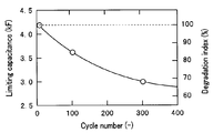
図4に示すように、電池10の容量と相関関係のある限界容量CLは、充放電回数が増加すると減少する。このため、例えば、初期限界容量CL0と測定した限界容量CLとの比である劣化指数(Degradation index)として、電池の劣化度を示すことができる。図4に示した例では、300サイクルの充放電を行った後の電池の劣化指数(DI)は68%である。
上記説明のように、実施形態の電池システム1による劣化度算出は、ナイキストプロットの半円部(図1参照)の解析等の複雑な処理が不要である。このため、電池システム1は、ユーザーが電池の使用中に、その電池の劣化度を簡単に測定できる。
<電池システム1の製造方法及び評価方法>
ここで、図5に示すフローチャートを用いて、電池システム1の評価方法について更に説明する。
ここで、図5に示すフローチャートを用いて、電池システム1の評価方法について更に説明する。
<ステップS10>
所定の仕様の電池10を有する電池システム1が大量に製造される。なお、この段階では、記憶部33には固有情報は記憶されていない。
所定の仕様の電池10を有する電池システム1が大量に製造される。なお、この段階では、記憶部33には固有情報は記憶されていない。
<ステップS11>
大量生産された複数の電池10の中から少なくとも1個の電池が選択される。選択される電池の数は生産数にもよるが複数個であることが好ましく、生産中の変動を考慮すると初期ロットと最終ロットとからも、それぞれ選択されることが特に好ましい。
大量生産された複数の電池10の中から少なくとも1個の電池が選択される。選択される電池の数は生産数にもよるが複数個であることが好ましく、生産中の変動を考慮すると初期ロットと最終ロットとからも、それぞれ選択されることが特に好ましい。
<ステップS12>
ステップS11で選択された電池は、40℃以上の所定温度に加熱された状態で、交流インピーダンス法により測定される。すると、図3に示したナイキストプロットが取得される。なお、測定温度は40℃~70℃である。すでに説明したように、前記温度範囲以上では0.5mHz以上10mHz未満の周波数において限界容量が取得できる。前記温度範囲以下であれば加熱により電池が故障するおそれが少ない。更に、長期信頼性担保の観点から40℃~60℃未満がより好ましい。すなわち、測定温度は、電解液、セパレータ及びパッケージの耐熱性を考慮して決定される。
ステップS11で選択された電池は、40℃以上の所定温度に加熱された状態で、交流インピーダンス法により測定される。すると、図3に示したナイキストプロットが取得される。なお、測定温度は40℃~70℃である。すでに説明したように、前記温度範囲以上では0.5mHz以上10mHz未満の周波数において限界容量が取得できる。前記温度範囲以下であれば加熱により電池が故障するおそれが少ない。更に、長期信頼性担保の観点から40℃~60℃未満がより好ましい。すなわち、測定温度は、電解液、セパレータ及びパッケージの耐熱性を考慮して決定される。
なお、充放電回数1サイクルの電池で取得されるナイキストプロットは、不安定であるため、数サイクル、例えば、3サイクル後の電池の特性を初期特性とすることが好ましい。
<ステップS13>
取得されたナイキストプロットから、インピーダンスの軌跡が、Z’軸に略垂直となる周波数が判明する。例えば、測定周波数のうち最も低い周波数1mHzのインピーダンスZ’に対して、95%以上のインピーダンスZ’を示す周波数が測定周波数として決定される。
取得されたナイキストプロットから、インピーダンスの軌跡が、Z’軸に略垂直となる周波数が判明する。例えば、測定周波数のうち最も低い周波数1mHzのインピーダンスZ’に対して、95%以上のインピーダンスZ’を示す周波数が測定周波数として決定される。
測定周波数は、限界容量を取得するためには、10mHz未満、好ましくは3mHz未満である。一方、測定周波数が0.5mHz以上、好ましくは1mHz以上であれば、測定時間が実用上、許容範囲内である。複数の温度で測定を行い、インピーダンスの軌跡が、Z’軸に略垂直となる最も低い温度を測定温度としてもよい。
<ステップS14>
測定温度における測定周波数fのインピーダンス測定値Z”から、以下の(式1)により、初期限界容量CL0が算出される。
測定温度における測定周波数fのインピーダンス測定値Z”から、以下の(式1)により、初期限界容量CL0が算出される。
CL0=-1/(2πfZ”) (式1)
例えば、Z”=-0.0857Ω、f=1mHzでは、CL0=1860Fとなる。
例えば、Z”=-0.0857Ω、f=1mHzでは、CL0=1860Fとなる。
<ステップS15>
それぞれの電池システム1の記憶部33に、初期限界容量と、測定周波数と、測定温度と、を含む固有情報が記憶される。そして出荷される。すなわち、ここまでの工程は製造時の工程である。
それぞれの電池システム1の記憶部33に、初期限界容量と、測定周波数と、測定温度と、を含む固有情報が記憶される。そして出荷される。すなわち、ここまでの工程は製造時の工程である。
<ステップS16>
出荷後に、すなわち、ユーザーが使用開始後に、電池10の劣化度を測定するときには、電池システム1の記憶部33に記憶されている測定温度に電池10が加熱される。電源部20は、温度測定部50により測定される電池10の温度が測定温度になるまで待機する。測定温度になったら、電源部20は、測定周波数の交流信号を電池10に印加する。そして、測定部32によりインピーダンスが測定される。
出荷後に、すなわち、ユーザーが使用開始後に、電池10の劣化度を測定するときには、電池システム1の記憶部33に記憶されている測定温度に電池10が加熱される。電源部20は、温度測定部50により測定される電池10の温度が測定温度になるまで待機する。測定温度になったら、電源部20は、測定周波数の交流信号を電池10に印加する。そして、測定部32によりインピーダンスが測定される。
<ステップS17>
算出部34は、測定周波数及び測定したインピーダンスから、電池10の限界容量CLを算出する。更に算出部は、初期限界容量CL0を基準に劣化度を算出する。算出された劣化度は、表示部35に表示される。
算出部34は、測定周波数及び測定したインピーダンスから、電池10の限界容量CLを算出する。更に算出部は、初期限界容量CL0を基準に劣化度を算出する。算出された劣化度は、表示部35に表示される。
そして、必要に応じて、ステップS16、S17が繰り返し行われる。なお、劣化度が所定値以下となった場合に、表示部35に警告を表示してもよい。
以上の説明のように、電池システム1によれば電池の劣化度評価を簡単に行うことができる。
なお、記憶部33に記憶する初期限界容量CL0及び算出部34が算出する限界容量CLは、(式1)により算出される、単位が「F」の容量に限られるものではない。すなわち、初期限界容量CL0と測定した限界容量CLとの比である劣化指数は、例えば、同じ周波数で測定された、初期インピーダンスと測定インピーダンスとの比からも算出することもできる。すなわち、電池システム1においては、限界容量と比例関係にある何らかの指数を限界容量と見なして、記憶し取得してもよい。言い換えれば、電池システム1において、「限界容量」は「限界容量と比例関係にある指数」を意味する。
また、限界容量は測定方法、測定条件、又は算出方法が異なると、値が異なることがある。例えば、実施形態の電池システム1が取得する「限界容量」は、0.1mHz以下の超低周波で取得される限界容量と同じ値とは限らない。しかし、初期限界容量CL0と限界容量CLとを同じ測定方法、同じ測定条件及び同じ算出方法で測定するため、(限界容量CL/初期限界容量CL0)という比として算出される劣化度(劣化指数)の信頼性は担保されている。
<第2実施形態>
次に、第2実施形態の電池システム1Aについて説明する。電池システム1Aは、電池システム1と類似しているため、同じ構成要素には同じ符号を付し説明は省略する。
次に、第2実施形態の電池システム1Aについて説明する。電池システム1Aは、電池システム1と類似しているため、同じ構成要素には同じ符号を付し説明は省略する。
電池システム1Aでは、記憶部33が複数の測定周波数を記憶し、電源部20が複数の測定周波数を電池10に印加し、複数の測定周波数のうち最も低周波の測定周波数を印加したときの測定部32が測定したインピーダンスの測定値に対して、95%以上の値の複数のインピーダンス測定値を用いて、算出部34が限界容量を算出する。
例えば、電池システム1Aは、2.00mHz、1.59mHz、1.26mHz、1.00mHzの4つの測定周波数を用いる。すなわち、例えば以下に示すように4つの周波数のインピーダンスを取得する。
Z”(f=2.00mHz)=-0.0474Ω
Z”(f=1.59mHz)=-0.0569Ω
Z”(f=1.26mHz)=-0.0697Ω
Z”(f=1.00mHz)=-0.0857Ω
最も低周波のf=1.00mHzにおけるインピーダンスに対する、各周波数におけるインピーダンスの比は以下の通りである。
Z”(f=1.59mHz)=-0.0569Ω
Z”(f=1.26mHz)=-0.0697Ω
Z”(f=1.00mHz)=-0.0857Ω
最も低周波のf=1.00mHzにおけるインピーダンスに対する、各周波数におけるインピーダンスの比は以下の通りである。
Z”(f=2.00mHz)/Z”(f=1.00mHz)×100=92%
Z”(f=1.59mHz)/Z”(f=1.00mHz)×100=98%
Z”(f=1.26mHz)/Z”(f=1.00mHz)×100=98%
Z”(f=1.00mHz)/Z”(f=1.00mHz)×100=100%
そして、算出部34は、比が95%以上の、Z”(f=1.59mHz)、Z”(f=1.26mHz)及びZ”(f=1.00mHz)の3つの測定値を用いて、限界容量を算出する。言い換えれば、比が95%未満のZ”(f=2.00mHz)は、インピーダンスの軌跡が、Z’軸に略垂直ではない範囲と見なして、算出には用いない。
Z”(f=1.59mHz)/Z”(f=1.00mHz)×100=98%
Z”(f=1.26mHz)/Z”(f=1.00mHz)×100=98%
Z”(f=1.00mHz)/Z”(f=1.00mHz)×100=100%
そして、算出部34は、比が95%以上の、Z”(f=1.59mHz)、Z”(f=1.26mHz)及びZ”(f=1.00mHz)の3つの測定値を用いて、限界容量を算出する。言い換えれば、比が95%未満のZ”(f=2.00mHz)は、インピーダンスの軌跡が、Z’軸に略垂直ではない範囲と見なして、算出には用いない。
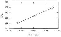
例えば、図6に示すように、横軸をインピーダンス-Z”、縦軸を1/ω(なお、ω=2πf)とし、上記3つの測定値を直線近似した場合の直線の傾きから限界容量CLが算出される。図6では、CL=2040Fとなる。なお、直線近似は原点からの直線に近似してもよい。
また、限界容量の算出方法は、それぞれの周波数におけるインピーダンスから算出した限界容量の平均値等でもよい。更に、限界容量は、(式2)に示すキャパシターのインピーダンスに対する等価回路式を用いたフィッティングにより算出してもよい。
Z=1/(jωC) (式2)
本実施形態の電池システム1Aは、電池システム1が有する効果を有し、電池システム1よりも測定時間が長くなるが、より精度の高い劣化度の算出が可能である。
本実施形態の電池システム1Aは、電池システム1が有する効果を有し、電池システム1よりも測定時間が長くなるが、より精度の高い劣化度の算出が可能である。
なお、測定周波数の数は電池システムの仕様により決定されるが、2以上であれば効果があり、10以下であれば測定時間が許容範囲内である。
<第3実施形態>
次に、第3実施形態の電池システム1Bについて説明する。電池システム1Bは、電池システム1、1Aと類似しているため、同じ構成要素には同じ符号を付し説明は省略する。
次に、第3実施形態の電池システム1Bについて説明する。電池システム1Bは、電池システム1、1Aと類似しているため、同じ構成要素には同じ符号を付し説明は省略する。
電池10によっては、充電率SOCが異なると、交流インピーダンス法により取得される限界容量の値が変化することがある。電池システム1では、例えばSOC≒100%の場合の初期限界容量CL0を測定し記憶しておいて、SOC≒100%の状態(直流成分=4.2V)で測定することで、劣化度を算出する。
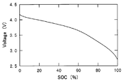
これに対して、電池システム1Aでは、記憶部33に、図7、図8に示す初期の電池の充電率SOCと電圧との関係及び充電率SOCと初期限界容量CL0との関係を記憶している。
そして、電源部20は、劣化度を取得するための測定直前の電池の電圧を基準としてインピーダンスを測定する。算出部34は電池の電圧から充電率SOCを判断し、充電率SOCに応じた初期限界容量CL0を用いて劣化度を算出する。
本実施形態の電池システム1Bは、電池システム1、1Aが有する効果を有し、より精度の高い劣化度の算出が可能である。
<第4実施形態>
次に、第2実施形態の電池システム1Cについて説明する。電池システム1Cは、電池システム1~1Bと類似しているため、同じ構成要素には同じ符号を付し説明は省略する。
次に、第2実施形態の電池システム1Cについて説明する。電池システム1Cは、電池システム1~1Bと類似しているため、同じ構成要素には同じ符号を付し説明は省略する。
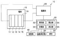
図9に示すように、電池システム1Cは時間を計測する時計60を、更に具備している。なお、電池システム1Cが他のシステムの一部として使用されている場合等において、他のシステムの時計のデータを利用可能な場合は、専用の構成部材としての時計60は不要である。
そして、記憶部33は、算出部34が算出した劣化度と、時計60のデータをもとにした電池10の使用時間と、を記憶している。ここで使用時間とは、電池10の充放電が定常的に行われ劣化が進行するようになってからの時間であり、具体的には使用者が電池10の使用を開始してからの時間である。
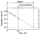
図10に示すように、電池10の劣化度は使用時間(充放電回数)に応じて減少していく。そして、劣化指数(限界容量CL/初期限界容量CL0)が、例えば、60%になると新しい電池と交換することが好ましい。
電池システム1Cでは、算出部34が、記憶部33に記憶されている使用時間及び劣化度をもとに、電池の余命(remaining lifetime)を算出する。例えば、図10に示すように算出部34は、劣化度の経時変化を外挿することで、余命を算出する。算出された余命は、劣化度とともに表示部35に表示される。
電池システム1Cは、電池システム1等の効果を有し、更に、使用者にとって有益な情報である電池の余命を算出できる。なお、電池10の寿命(lifetime)は使用頻度(充放電頻度)により大きく異なる。しかし、電池システム1Cは、その電池10の使用状態に基づいて余命を算出する。このため、正確な情報を取得することができる。
なお、電池システム1B、1Cにおいても電池システム1Aと同様に複数の測定周波数を用いて劣化度を算出してもよい。
また、以上の説明では、リチウムイオン二次電池を例に説明したが、電池10としては各種の二次電池であってもよい。
すなわち、本発明は、上述した実施形態に限定されるものではなく、本発明の要旨を変えない範囲において、種々の変更、改変、例えば、実施形態の構成要素の組み合わせ等が可能である。
本出願は、2012年10月5日に日本国に出願された特願2012-223124号を優先権主張の基礎として出願するものであり、上記の開示内容は、本願明細書、請求の範囲、図面に引用されたものとする。
Claims (9)
- 劣化度が測定される二次電池と、
測定周波数及び測定温度と、前記二次電池と同じ仕様の一の二次電池の初期限界容量と、を含む固有情報を記憶する記憶部と、
前記二次電池の温度を測定する温度測定部と、
前記記憶部の情報をもとに、40℃以上70℃以下の前記測定温度の前記二次電池に、0.5mHz以上10mHz未満の前記測定周波数の交流信号を印加する電源部と、
前記電源部が印加した前記交流信号により、前記二次電池のインピーダンスを測定する測定部と、
前記測定部の測定値を用いて算出する前記二次電池の限界容量と、前記初期限界容量と、を用いて前記劣化度を算出する算出部と、を具備することを特徴とする電池システム。 - 前記二次電池を前記測定温度に加熱する加熱部を、更に具備することを特徴とする請求項1に記載の電池システム。
- 前記測定周波数が、1mHz以上3mHz未満であることを特徴とする請求項2に記載の電池システム。
- 前記記憶部が、複数の前記測定周波数を記憶し、
前記電源部が、前記複数の測定周波数を前記二次電池に印加し、
前記算出部が、前記複数の測定周波数による複数の測定値を用いて前記限界容量を算出することを特徴とする請求項3に記載の電池システム。 - 前記算出部が、前記複数の測定周波数のうちの最も低い周波数による測定値に対して、95%以上の値の測定値を用いて、前記限界容量を算出することを特徴とする請求項4に記載の電池システム。
- 前記固有情報が、電圧の充電率依存性情報及び前記初期限界容量の充電率依存性情報を含み、
前記算出部が、充電率に応じた前記初期限界容量を用いることを特徴とする請求項5に記載の電池システム。 - 時計を、更に具備し、
前記記憶部が、前記算出部が算出する劣化度及び前記電池の使用時間を記憶し、
前記算出部が、前記劣化度及び前記使用時間をもとに、前記電池の余命(remaining lifetime)を算出することを特徴とする請求項3から請求項6のいずれか1項に記載の電池システム。 - 前記二次電池が、リチウムイオン二次電池であることを特徴とする請求項1から請求項7のいずれか1項に記載の電池システム。
- それぞれが二次電池を具備する複数の電池システムを製造する工程と、
一の前記二次電池の初期限界容量を、40℃以上70℃以下の測定温度で測定する工程と、
電池システムの記憶部に、測定周波数、前記測定温度及び前記初期限界容量を含む固有情報を記憶する工程と、
前記電池システムの前記二次電池を前記測定温度に加熱する工程と。
前記測定温度の前記二次電池に、0.5mHz以上10mHz未満の前記測定周波数の交流信号を印加して、前記二次電池のインピーダンスを測定する工程と、
前記インピーダンスを用いて算出する前記二次電池の限界容量と、前記初期限界容量と、を用いて劣化度を算出する工程と、を具備することを特徴とする電池システムの評価方法。
Priority Applications (1)
| Application Number | Priority Date | Filing Date | Title |
|---|---|---|---|
| US14/433,447 US9531040B2 (en) | 2012-10-05 | 2013-10-04 | Battery system and method for evaluating battery system |
Applications Claiming Priority (2)
| Application Number | Priority Date | Filing Date | Title |
|---|---|---|---|
| JP2012223124A JP6004334B2 (ja) | 2012-10-05 | 2012-10-05 | 電池システム及び電池システムの評価方法 |
| JP2012-223124 | 2012-10-05 |
Publications (1)
| Publication Number | Publication Date |
|---|---|
| WO2014054796A1 true WO2014054796A1 (ja) | 2014-04-10 |
Family
ID=50435114
Family Applications (1)
| Application Number | Title | Priority Date | Filing Date |
|---|---|---|---|
| PCT/JP2013/077136 Ceased WO2014054796A1 (ja) | 2012-10-05 | 2013-10-04 | 電池システム及び電池システムの評価方法 |
Country Status (3)
| Country | Link |
|---|---|
| US (1) | US9531040B2 (ja) |
| JP (1) | JP6004334B2 (ja) |
| WO (1) | WO2014054796A1 (ja) |
Cited By (5)
| Publication number | Priority date | Publication date | Assignee | Title |
|---|---|---|---|---|
| CN105866690A (zh) * | 2016-03-28 | 2016-08-17 | 广州市香港科大霍英东研究院 | 一种基于电容传感器的电池状态检测方法及系统 |
| CN106371030A (zh) * | 2016-08-29 | 2017-02-01 | 丹阳亿豪电子科技有限公司 | 一种非确定性推理的新能源汽车电池故障诊断方法 |
| US10281530B2 (en) | 2016-09-06 | 2019-05-07 | Primearth Ev Energy Co., Ltd. | Battery capacity measuring device and battery capacity measuring method |
| EP3505946A1 (en) | 2017-12-27 | 2019-07-03 | Primearth EV Energy Co., Ltd. | Battery state estimation device and battery state estimation method |
| JPWO2023127319A1 (ja) * | 2021-12-28 | 2023-07-06 |
Families Citing this family (16)
| Publication number | Priority date | Publication date | Assignee | Title |
|---|---|---|---|---|
| DE102014205495A1 (de) * | 2014-03-25 | 2015-10-01 | Robert Bosch Gmbh | Elektronischer Batteriesensor und Verfahren zur Bestimmung eines Innenwiderstandes einer Batterie |
| US10191479B2 (en) * | 2015-09-29 | 2019-01-29 | General Electric Company | Methods and systems for network-based detection of component wear |
| GB2556076B (en) | 2016-11-17 | 2022-02-23 | Bboxx Ltd | Method |
| JP6508729B2 (ja) * | 2016-12-02 | 2019-05-08 | トヨタ自動車株式会社 | 電池状態推定装置 |
| JP6575548B2 (ja) * | 2017-03-22 | 2019-09-18 | トヨタ自動車株式会社 | 電池状態推定装置 |
| JP6561407B2 (ja) | 2017-04-07 | 2019-08-21 | 学校法人早稲田大学 | 組電池、電池モジュールおよび電池モジュールの評価方法 |
| CN109671997B (zh) * | 2017-10-13 | 2021-10-19 | 神讯电脑(昆山)有限公司 | 电子装置与充电方法 |
| JP7025287B2 (ja) * | 2017-12-27 | 2022-02-24 | プライムアースEvエナジー株式会社 | 電池状態推定装置及び電池状態推定方法 |
| JP7070224B2 (ja) * | 2018-08-08 | 2022-05-18 | トヨタ自動車株式会社 | 電池情報処理システムおよび電池情報処理方法 |
| JP7116484B2 (ja) * | 2018-09-19 | 2022-08-10 | 学校法人早稲田大学 | 電気化学システム、および、電気化学システムの作動方法 |
| JP7157909B2 (ja) * | 2018-12-20 | 2022-10-21 | トヨタ自動車株式会社 | 電池容量の推定方法、および電池容量の推定装置 |
| US11415634B2 (en) | 2019-05-20 | 2022-08-16 | Waikatolink Limited | Battery performance assessment method and apparatus |
| WO2021040146A1 (en) * | 2019-08-27 | 2021-03-04 | Samsung Electronics Co., Ltd. | Method and system for determining health parameter of a battery |
| JP2022007515A (ja) * | 2020-06-26 | 2022-01-13 | 株式会社デンソー | 電池診断システム |
| JP7792094B2 (ja) * | 2022-02-08 | 2025-12-25 | メタウォーター株式会社 | 情報処理システム、情報処理装置、情報処理方法及びプログラム |
| US12451538B2 (en) * | 2022-05-03 | 2025-10-21 | GM Global Technology Operations LLC | Closed loop thermal control and estimation of a parameter of a battery assembly |
Citations (1)
| Publication number | Priority date | Publication date | Assignee | Title |
|---|---|---|---|---|
| JP2011038857A (ja) * | 2009-08-07 | 2011-02-24 | Sanyo Electric Co Ltd | 容量維持率判定装置、バッテリシステムおよびそれを備える電動車両 |
Family Cites Families (2)
| Publication number | Priority date | Publication date | Assignee | Title |
|---|---|---|---|---|
| JPH0843507A (ja) | 1994-08-04 | 1996-02-16 | Nippon Telegr & Teleph Corp <Ntt> | Ni系電池の劣化状態検知方法 |
| JP5088081B2 (ja) | 2007-10-12 | 2012-12-05 | 富士通株式会社 | 電池の測定方法及び電池の製造方法 |
-
2012
- 2012-10-05 JP JP2012223124A patent/JP6004334B2/ja active Active
-
2013
- 2013-10-04 WO PCT/JP2013/077136 patent/WO2014054796A1/ja not_active Ceased
- 2013-10-04 US US14/433,447 patent/US9531040B2/en not_active Expired - Fee Related
Patent Citations (1)
| Publication number | Priority date | Publication date | Assignee | Title |
|---|---|---|---|---|
| JP2011038857A (ja) * | 2009-08-07 | 2011-02-24 | Sanyo Electric Co Ltd | 容量維持率判定装置、バッテリシステムおよびそれを備える電動車両 |
Cited By (7)
| Publication number | Priority date | Publication date | Assignee | Title |
|---|---|---|---|---|
| CN105866690A (zh) * | 2016-03-28 | 2016-08-17 | 广州市香港科大霍英东研究院 | 一种基于电容传感器的电池状态检测方法及系统 |
| CN106371030A (zh) * | 2016-08-29 | 2017-02-01 | 丹阳亿豪电子科技有限公司 | 一种非确定性推理的新能源汽车电池故障诊断方法 |
| US10281530B2 (en) | 2016-09-06 | 2019-05-07 | Primearth Ev Energy Co., Ltd. | Battery capacity measuring device and battery capacity measuring method |
| EP3505946A1 (en) | 2017-12-27 | 2019-07-03 | Primearth EV Energy Co., Ltd. | Battery state estimation device and battery state estimation method |
| US10976372B2 (en) | 2017-12-27 | 2021-04-13 | Primearth Ev Energy Co., Ltd. | Battery state estimation device and battery state estimation method |
| JPWO2023127319A1 (ja) * | 2021-12-28 | 2023-07-06 | ||
| JP7639947B2 (ja) | 2021-12-28 | 2025-03-05 | 株式会社デンソー | 電池診断システム |
Also Published As
| Publication number | Publication date |
|---|---|
| US20150303533A1 (en) | 2015-10-22 |
| JP6004334B2 (ja) | 2016-10-05 |
| US9531040B2 (en) | 2016-12-27 |
| JP2014074686A (ja) | 2014-04-24 |
Similar Documents
| Publication | Publication Date | Title |
|---|---|---|
| JP6004334B2 (ja) | 電池システム及び電池システムの評価方法 | |
| JP5850492B2 (ja) | 電池システムおよび電池の評価方法 | |
| US11686699B2 (en) | System and method for anomaly detection and total capacity estimation of a battery | |
| CN106324508B (zh) | 电池健康状态的检测装置及方法 | |
| CN102761141B (zh) | 一种锂离子动力蓄电池的电量校正和控制方法 | |
| TWI591358B (zh) | 電池狀態計算裝置及電池狀態計算方法 | |
| JP5994521B2 (ja) | 状態推定装置、開放電圧特性生成方法 | |
| EP3021127A1 (en) | Method for estimating state of electricity storage device | |
| JP2016085062A (ja) | 電池劣化判定装置及び方法 | |
| CN103884991A (zh) | 一种单体电池直流内阻的测试方法 | |
| CN103399277A (zh) | 一种动力电池实际容量估算方法 | |
| CN104198948A (zh) | 一种锂电池自放电的测量方法 | |
| JPWO2017033311A1 (ja) | 劣化度推定装置及び劣化度推定方法 | |
| WO2014103705A1 (ja) | 蓄電デバイスの寿命予測装置及び蓄電デバイスの寿命予測方法 | |
| US20110215761A1 (en) | Method for determining the state of charge of a battery in charging or discharging phase | |
| CN106443467A (zh) | 基于充电过程的锂离子电池充入电量建模方法与应用 | |
| JP2014102248A (ja) | 蓄電状態検出装置 | |
| JP6342612B2 (ja) | 二次電池診断装置及び二次電池診断方法 | |
| JP5754392B2 (ja) | 電池の検査方法 | |
| KR20150045600A (ko) | 배터리 시험기 및 그 제어방법 | |
| CN102879743A (zh) | 锂离子电池剩余电量值实时分析计算法 | |
| CN108963354A (zh) | 锂离子电池的状态推定装置和状态推定方法 | |
| CN103487696A (zh) | 一种母排温升一致性评价方法及装置 | |
| WO2019058666A1 (ja) | 二次電池劣化検出システム | |
| CN107589374A (zh) | 电动汽车电池包容量估算方法 |
Legal Events
| Date | Code | Title | Description |
|---|---|---|---|
| 121 | Ep: the epo has been informed by wipo that ep was designated in this application |
Ref document number: 13843507 Country of ref document: EP Kind code of ref document: A1 |
|
| WWE | Wipo information: entry into national phase |
Ref document number: 14433447 Country of ref document: US |
|
| NENP | Non-entry into the national phase |
Ref country code: DE |
|
| 122 | Ep: pct application non-entry in european phase |
Ref document number: 13843507 Country of ref document: EP Kind code of ref document: A1 |