WO2014054436A1 - 着用物品 - Google Patents
着用物品 Download PDFInfo
- Publication number
- WO2014054436A1 WO2014054436A1 PCT/JP2013/075457 JP2013075457W WO2014054436A1 WO 2014054436 A1 WO2014054436 A1 WO 2014054436A1 JP 2013075457 W JP2013075457 W JP 2013075457W WO 2014054436 A1 WO2014054436 A1 WO 2014054436A1
- Authority
- WO
- WIPO (PCT)
- Prior art keywords
- edge
- elastic
- wearing article
- fastener assembly
- side panel
- Prior art date
- Legal status (The legal status is an assumption and is not a legal conclusion. Google has not performed a legal analysis and makes no representation as to the accuracy of the status listed.)
- Ceased
Links
Images




Classifications
-
- A—HUMAN NECESSITIES
- A61—MEDICAL OR VETERINARY SCIENCE; HYGIENE
- A61F—FILTERS IMPLANTABLE INTO BLOOD VESSELS; PROSTHESES; DEVICES PROVIDING PATENCY TO, OR PREVENTING COLLAPSING OF, TUBULAR STRUCTURES OF THE BODY, e.g. STENTS; ORTHOPAEDIC, NURSING OR CONTRACEPTIVE DEVICES; FOMENTATION; TREATMENT OR PROTECTION OF EYES OR EARS; BANDAGES, DRESSINGS OR ABSORBENT PADS; FIRST-AID KITS
- A61F13/00—Bandages or dressings; Absorbent pads
- A61F13/15—Absorbent pads, e.g. sanitary towels, swabs or tampons for external or internal application to the body; Supporting or fastening means therefor; Tampon applicators
- A61F13/45—Absorbent pads, e.g. sanitary towels, swabs or tampons for external or internal application to the body; Supporting or fastening means therefor; Tampon applicators characterised by the shape
- A61F13/49—Absorbent pads, e.g. sanitary towels, swabs or tampons for external or internal application to the body; Supporting or fastening means therefor; Tampon applicators characterised by the shape specially adapted to be worn around the waist, e.g. diapers, nappies
- A61F13/49007—Form-fitting, self-adjusting disposable diapers
- A61F13/49009—Form-fitting, self-adjusting disposable diapers with elastic means
- A61F13/49014—Form-fitting, self-adjusting disposable diapers with elastic means the elastic means is located at the side panels
Definitions
- the present invention relates to a wearing article suitable for use as a disposable diaper, a disposable diaper cover, an incontinence pad holder, or the like.
- wearing articles that detachably connect the front and rear waist regions of the wearing article through fasteners.
- the worn article is a disposable diaper, it is known under the name of an open diaper.
- wearing article is also known.
- a wing that is elastically stretchable in the lateral direction of the diaper is also known.
- a disposable diaper described in Japanese Patent Application Laid-Open No. 2005-95648 includes an elastic wing extending in a lateral direction from a side edge portion of a rear waist region, and a tape fastener is attached to a tip portion of the elastic wing. It has been.
- the elastic wing is formed by sandwiching an elastic plastic film in a laterally stretched state with two nonwoven fabrics, and can be expanded and contracted in the lateral direction.
- the tape fastener is used to detachably connect the front waist region and the rear waist region via the elastic wing, and the dimension in the direction intersecting the extending direction of the tape fastener is the tip portion of the elastic wing. In other words, the tape fastener is narrower than the elastic wing.
- the elastic wing is pulled from the rear waist region toward the front waist region, and the tape fastener is held at a required portion of the front waist region in an elastically stretched state.
- the elastic wings pulled in such a manner extend in the lateral direction while being in close contact with the front waist region covering the skin of the diaper wearer with the central portion in the vertical direction, in other words, the central portion in the width direction being in tension.
- the inner and outer edges of the elastic wing may warp away from the front waist area.
- the outer surface of the diaper worn may be impaired and the outer surface may be uncomfortable.
- shirts and skirts worn by infants may be inflated to deteriorate the appearance of the shirts and skirts.
- the place which this invention makes a subject is provision of the wearing article improved so that the external appearance in the wearing article when it exists in a wearing state can be kept favorable.
- the present invention provides a chassis having a longitudinal direction and a transverse direction orthogonal to each other, and having a front waist region, a rear waist region, and a crotch region, and extending from both side edges of the chassis.
- a side panel having a proximal edge, a distal edge, an inner edge, an outer edge, and a central region between the inner and outer edges, and the distal edge of the side panel
- a wearing article including a fastener assembly for positioning and connecting the front and rear waist regions to each other.
- the features of the present invention are as follows. That is, in the side panel, the longitudinal separation between the inner edge portion and the outer edge portion gradually decreases from the proximal edge toward the distal edge,
- the outer edge portion is formed by an extension portion extending along the inner edge portion and the outer edge portion, and an additional material that is separate from the extension portion joined to the extension portion. It is characterized by.
- At least one of the inner edge and the outer edge of the side panel extending from both side edges of the chassis forms a central region in the vertical direction of the side panel. Formed by an extended portion of the sheet material and an additional material extending along one edge of the sheet material but separate from the extended portion and joined to the extended portion. Since it is difficult to deform compared, the inner edge and outer edge of the side panel in worn articles such as worn diapers are less likely to wrinkle, bend and warp, and adhere well to the outer surface of the front waist area, The smoothness of the outer surface is not impaired.
- FIG. 3 illustrates certain embodiments of the invention and include selective and preferred embodiments, as well as essential features of the invention.
- the partial fracture top view of a disposable diaper shown as an example of a wearing article.
- the elements on larger scale of FIG. FIG. 3 is an enlarged sectional view taken along line III-III in FIG. 2.
- the figure which shows an example of the process of attaching an inner side elastic body and an outer side elastic body to an elastic sheet.
- FIG. 3 which shows an example of an embodiment.
- FIG. 3 which shows an example of an embodiment.
- FIG. 2 shows an example of an embodiment.
- the following embodiments relate to the wearing articles shown in FIGS. 1 to 7 and include selective and preferable configurations as well as the indispensable configurations of the invention.
- the diaper 1 is of an open type and has a substantially rectangular chassis 20.
- the chassis 20 includes a liquid-permeable body-side liner 2 and a liquid-impervious outer cover 3 and an absorbent body 10 interposed therebetween.
- the body side liner 2 and the outer cover 3 overlap at a portion extending from the peripheral edge of the absorbent body 10 and are joined to each other via, for example, a hot melt adhesive (not shown).
- the horizontal direction and vertical direction of the diaper 1 are indicated by double-headed arrows X and Y.
- the chassis 20 has a front waist region 6, a rear waist region 7, and a crotch region 8 interposed between both the regions 6 and 7 in the longitudinal direction Y.
- tape-like waist elastic bodies 11 and 12 extending in the lateral direction X are between the body side liner 2 and the outer cover 3, and contract in an expanded state to at least one of these. Fixed as possible.
- a plurality of leg elastic bodies 13 extending in the longitudinal direction Y along the side edge portion 21 of the chassis 20 are interposed between the body side liner 2 and the outer cover 3, and extend to at least one of them. It is fixed so that it can contract in a state.
- the leg elastic body 13 reaches at least the rear waist region 7 of the front and rear waist regions 6, 7.
- the side panel 30 extends in the lateral direction X from the side edge 21 of the rear waist region 7 in the chassis 20.
- the central region 45 in the vertical direction Y has elasticity in the horizontal direction X.
- the elastic panel material 31 is formed.
- the side panel 30 also has a proximal edge 32, a distal edge 33, an inner edge 34, and an outer edge 36, in addition to the central region 45, with the proximal edge 32 and the distal edge
- the edge 33 extends in the longitudinal direction Y, while the inner edge 34 and the outer edge 36 extend so as to approach each other between the proximal edge 32 and the distal edge 33.
- the proximal edge 32 is between the outer cover 3 and the barrier cuff 16 described later, and is joined to these 3 and 16 via the hot melt adhesive 17.
- the inner edge 34 and the outer edge 36 are formed by an extended portion in the longitudinal direction Y of the elastic panel material 31 that forms the central region 45.
- the diaper 1 includes a fastener assembly 37, and the fastener assembly 37 includes a tape tab 38 attached to the elastic panel material 31 and a fastening portion 39.
- the tape tab 38 is formed of, for example, a non-extensible fiber nonwoven fabric or a plastic film, and has a fixed area 38a and an extended area 38b.
- the fixing area 38a is joined to the side panel 30 so as not to be peeled off through a joining means (not shown) such as a hot melt adhesive.
- the extension region 38b extends from the distal edge 33 in the lateral direction X and can be gripped, and a fastening portion 39 is fixed to the inner surface thereof.
- the fastening part 39 is detachably fastened to a target area (not shown) provided on the outer surface of the front waist area 6 or an appropriate part in place thereof, and is known by a trade name Velcro (registered trademark) or the like. For example, it is formed by a hook element or adhesive of a mechanical fastener.
- Each of the side edges 21 of the chassis 20 has a barrier cuff 16 extending in the longitudinal direction Y.
- the barrier cuff 16 is formed of a sheet material such as a nonwoven fabric on the back having water repellency, more preferably water repellency, for example, an outer proximal edge 16a and a distal edge 16b parallel to each other, and a front edge 16c parallel to each other. And a rear edge 16d.
- the proximal edge 16a, the front edge 16c, and the rear edge 16d are joined to the chassis 20 via, for example, a hot melt adhesive 17.
- the distal edge portion 16 b is not joined to the chassis 20 at least in the crotch region 8 in the longitudinal direction Y.
- the distal edge portion 16b also has a sleeve 18, and a thread / strand or string-like elastic body 19 as a space means is stretched inside the sleeve 18 through, for example, a hot melt adhesive (not shown). It is fixed so that it can shrink.
- a hot melt adhesive not shown
- the elastic body 19 in the stretched state contracts, and the distal edge 16 b becomes The excrement is separated from the body side liner 2, the barrier cuff 16 rises with respect to the body side liner 2, a space is defined between the body side liner 2 and the barrier cuff 16, and is excreted on the body side liner 2. It has a function to contain.
- the side panel 30 has an inner edge 34 extending transversely X from the proximal edge 32 and intersects the proximal edge 32 at an angle ⁇ , and an outer edge 36 is the proximal edge 32. And intersect at an intersection angle ⁇ .
- the intersection angles ⁇ and ⁇ are in the range of 50-80 °, for example, and in the preferred side panel 30, the intersection angle ⁇ and the intersection angle ⁇ are equal.
- the dimension in the longitudinal direction Y of the proximal edge portion 32 is preferably in the range of 40 to 130 mm
- the dimension in the longitudinal direction Y of the distal edge portion 33 is preferably in the range of 20 to 100 mm.
- a preferable planar view shape of the side panel 30 in one embodiment of the present invention is an isosceles trapezoid.
- the fastening region 38 a of the fastener assembly 37 that is pulled in the direction around the waist has the leg elastic body 13 in the chassis 20 via the side panel 30 as indicated by phantom lines 46 and 47.
- a force can be applied so as to lift the diaper toward the upper side of the body of the diaper wearer, thereby preventing the diaper 1 from sliding down.
- the imaginary lines 46, 47 are connected to the inner edge portion 50 c of the joint portion 48 where the proximal edge portion 32 of the side panel 30 is joined to the chassis 20 and the barrier cuff 16 and the inner edge portion 38 c of the fastening region 38 a of the fastener assembly 37. And intersects the leg elastic body 13 extending toward the rear waist region 7.
- the elastic panel material 31 forming the side panel 30 is bent toward the outside of the diaper 1 along the inner edge 34 and the outer edge 36, and the inner side of each bent portion is inside.
- the inner multilayer portion 41 and the outer multilayer portion 42 are formed by interposing the elastic body 51 and the outer elastic body 52.
- the multi-layered portion here refers to the elastic panel material 31 with respect to the inner edge 34 and the outer edge 36 which are extended portions in the longitudinal direction Y of the elastic panel material 31 forming the central region 45 of the side panel 30. Means that separate materials, for example, the inner elastic body 41 and the outer elastic body 42 overlap.
- the elastic panel material 31 and the elastic panel material 31 and the inner elastic body 51 in the form of a string, a strand, or a string are connected to each other through a hot melt adhesive 43, for example.
- the yarns / strands or string-like outer elastic bodies 52 are joined to each other.
- the inner elastic body 51 and the outer elastic body 52 are additional materials for the elastic panel material 31 at the inner edge portion 34 and the outer edge portion 36, and can take the form of threads, ribbons, etc. It extends between the leading edge 32 and the distal edge 33 in an extended or non-extended state.
- the elastic bodies 51 and 52 in the stretched state are preferably 3.5 times or less, more preferably 2.5 times or less, and even more preferably 1.5 times or less, depending on their elastic modulus. If this is done, the inner edge 34 and the outer edge 36 will not be excessively contracted.
- the elastic panel material 31 can be elastically stretchable, such as an elastically stretchable nonwoven fabric including polyethylene fibers, polypropylene fibers and polyurethane fibers, an elastically stretchable nonwoven fabric formed of polyurethane fibers, and a polyurethane film. Can be used.
- the fixing region 38 a of the fastener assembly 37 is attached to the distal edge portion 33 of the side panel 30 using a bonding means (not shown) such as an adhesive or embossing / debossing.
- the fastener assembly 37 has a width W 3 in the longitudinal direction Y, and the width W 3 is smaller than the separation dimension D 1 between the inner multilayer portion 41 and the outer multilayer portion 42 at the distal edge 33, and the inner multilayer portion. 41 and the outer multilayer portion 42 are attached to the side panel 30 so as not to overlap.
- Preferred fastener assembly 37 is from the central portion or central portion thereof distal edge 33 having a separation dimension D 1 attached to the side panel 30 at a position close to the rear.
- the front and rear waist regions 6 and 7 are applied around the wearer's waist, the extension region 38b of the fastener assembly 37 is gripped, and the side panel 30 is pulled along the waist and the fastening portion 39 is pulled. Is attached to a required portion such as a target zone in the front waist region 6.
- the central region 45 in the longitudinal direction Y of the side panel 30 located on the extension of the fixed region 38a in the elastic panel material 31 is shown in FIG. It is equivalent to being stretched and stretched in the transverse direction X.
- the inner edge 34 and the outer edge 36 of the side panel 30 are not easily deformed by the presence of the folded elastic panel material 31 and the presence of the inner elastic body 51 and the outer elastic body 52 which are additional materials. In the state, it is difficult to cause wrinkles, bends, or warp toward the outer surface side of the side panel 30. Therefore, when the outer surface of the diaper 1 after wearing is viewed, the area where the side panel 30 is present is relatively smooth and does not impair the appearance of the diaper 1.
- the outer edge portion 36 that is difficult to be deformed causes the elastic body 12 of the rear waist region 7 to act on the elastic body 12 of the rear waist region 7 that acts on the fastener assembly 37. It also acts to make the contact with the wearer.
- the inner edge 38c of the fixing region 38a moves the leg elastic body 13 in the chassis 20 toward the upper side of the diaper wearer's body. A force is applied to pull up, and as described above, the diaper 1 can be prevented from sliding down.
- the inner elastic body 51 and / or the outer elastic body 52 can be attached to the inner surface of the side panel 30 and sandwiched by the elastic panel material 31.
- FIG. 4 is a diagram illustrating an example of a method of attaching the inner elastic body 51 and the outer elastic body 52 illustrated in FIGS. 2 and 3 to the elastic panel material 31.
- the web 300 of the elastic panel material 31 is running.
- a first arm 301 and a second arm 302 that reciprocate in the direction indicated by the double-headed arrow F are disposed upstream of the machine direction MD.
- a first continuous elastic body 351 in the form of a thread / strand or a string and a second continuous elastic body 352 in the form of a thread / strand or a string have a required elongation rate. And at the required speed.
- the web 300 and / or the first and second continuous elastic bodies 351 and 352 are preliminarily coated with a hot melt adhesive in a process not shown.
- the first and second arms 301 and 302 are required to supply the first and second continuous elastic bodies 351 and 352 to the required portions of the web 300 while turning.
- the composite web 310 of the illustrated example in which the undulations of the above pattern are repeated is obtained.
- the web 300 in order to cover each of the first and second continuous elastic bodies 351 and 352, the web 300 is folded along a folding guide line 305 indicated by an imaginary line and joined together. Thereafter, by cutting the composite web 310 along the cut line C extending in the cross direction CD, a pair of the side panels 30 that can be attached to the chassis 20 can be obtained.
- a fastener assembly 37 is attached to the side panel 30 in an appropriate process.
- FIG. 5 this is a view similar to FIG. 3 showing an example of the embodiment.
- the inner side on the outer surface side of the inner edge 34 As an additional material to the elastic panel material 31, the inner side on the outer surface side of the inner edge 34.
- the elastic body 51 and the elongated elastic covering sheet 53 are attached via the hot melt adhesive 43 to form the inner multilayer portion 41, while the outer elastic body is provided on the outer surface side of the outer edge 36 as another additional material.
- 52 and the elastic covering sheet 54 are attached via a hot-melt adhesive 43 to form the outer multilayer portion 42.
- the inner elastic body 51, the elastic covering sheet 53, the outer elastic body 52, and the elastic covering sheet 54 extend between the proximal edge portion 32 and the distal edge portion 33 in an extended state or a non-extended state.
- the inner elastic body 51 and the outer elastic body 52 are thus covered with the elastic covering sheet 53 and the elastic covering sheet 54 that are separate from the elastic panel material 31, or separate from the elastic panel material 31 if necessary.
- the elastic panel material 31 may be covered with an elastic covering sheet 53 or an elastic covering sheet 54 having a different elastic modulus.
- the embodiment of FIG. 4 can be changed to a mode in which one of the inner elastic body 51 and the outer elastic body 52 is not used.
- the inner elastic body 51 and the outer elastic body 52 can also be attached to the inner surface of the side panel 30.
- FIG. 6 this is also similar to FIG. 5 showing an example of the embodiment.
- a band-shaped elastic backing sheet 55 instead of the inner elastic body 51 and the elastic covering sheet 53 is interposed via a hot melt adhesive 43.
- a belt-like elastic backing sheet 56 which replaces the outer elastic body 52 and the elastic covering sheet 43, is added to the outer edge 36 as an additional material for the elastic panel material 31 by hot-melt bonding.
- the outer multilayer portion 42 is formed by being attached via the agent 43.
- These elastic backing sheets 55, 56 extend between the proximal edge 32 and the distal edge 33 in an extended or non-extended state.
- a panel material having an elastic modulus different from that of the elastic panel material 31 can be used for the elastic backing sheets 55 and 56.
- at least one of the elastic backing sheets 55 and 56 can be attached to the inner surface of the side panel 30.
- FIG. 7 this is also a view similar to FIG. 2 showing an example of the embodiment, but showing a part of the member broken.
- the inner elastic sheet 57 and the outer elastic sheet 58 which are sheet-like elastic members, are not stretched via the hot melt adhesive 43.
- the inner multilayer portion 41 and the outer multilayer portion 42 are formed.
- the inner elastic sheet 57 is between the inner edge 34 and the fastener assembly 37, more specifically between the inner edge 34 and the central region 45
- the outer elastic sheet 58 is between the outer edge 36 and the fastener assembly 37. More particularly, between the outer edge 36 and the central zone 45.
- the central region 45 is easily elastically extended, while the portion between the inner edge portion 34 and the central region 45 is provided.
- the inner multi-layered portion 41 and the outer multi-layered portion 42 that is a portion between the outer edge 36 and the central region 46 become difficult to extend, thereby suppressing deformation of the inner edge 34 and the outer edge 36. it can.
- the elastic modulus of the inner elastic sheet 57 and the outer elastic sheet 58 may be the same as or different from that of the elastic panel material 31.
- the inner edge portion 34, the outer edge portion 36, and the central region 45 are easily elastically stretched and difficult to stretch.
- the inner edge 34 and the outer edge 36 specimens having a width of 5 mm in the direction orthogonal to the extending direction and a length of 40 mm in the parallel direction are collected.
- the central region 45 a specimen having a width in the vertical direction Y of 5 mm and a length in the horizontal direction X of 40 mm is collected.
- the tensile speed is set to 50 mm / min and the elongation rate is 20%
- the stress generated in each specimen is compared, and it is determined that the specimen having the smaller stress is easily extended.
- the length of the specimen released from the extension after the specimen is extended by 20% should be 1.05 times or less of the original length within one minute. means.
- the side panel 30 can also be made of a non-extensible panel material in place of the elastic panel material 31 that can be repeatedly expanded and contracted in the illustrated example.
- a non-extensible panel material in place of the elastic panel material 31 that can be repeatedly expanded and contracted in the illustrated example.
- a non-extensible plastic film can be used.
- the additional material used for these non-extensible sheets may be an elastic material capable of repeating expansion and contraction, such as the inner elastic body 51 and the outer elastic body 52 in the illustrated example, It may be an inelastic material that cannot be repeatedly expanded and contracted.
- the present invention includes a chassis having a vertical direction and a horizontal direction orthogonal to each other, and having a front waist region, a rear waist region, and a crotch region, and extending from both side edges of the chassis, and a proximal edge, A side panel having a lateral edge, an inner edge, an outer edge, and a central region between the inner and outer edges, and the front and rear waist regions positioned at the distal edge of the side panel.
- a wearing article comprising a fastener assembly for coupling, In the side panel, the longitudinal separation between the inner edge and the outer edge is gradually reduced from the proximal edge toward the distal edge, The inner edge and the outer edge by the inner edge, an extension portion extending along the outer edge, and an additional material that is separate from the extension portion joined to the extension portion; It is formed.
- the present invention includes at least the following embodiments, which are adopted separately from each other or in combination.
- the additional material is an elastic material that extends in either an extended state or a non-extended state along the inner edge and the outer edge.
- the additional material is either a string / strand or a string or ribbon.
- the additional material is sandwiched by the extended portion folded over at the inner edge and the outer edge.
- the fastener assembly is located between the inner edge and the outer edge in the longitudinal direction, and the additional material is disposed between the inner edge and the fastener assembly in the longitudinal direction. , And at least one of the outer edge and the fastener assembly.
- the side panel has a trapezoidal shape, the distal edge extends in the longitudinal direction and is parallel to the proximal edge, the inner edge and the outer edge are equal in length, and The angle of intersection with the proximal edge is equal.
- the fastener assembly includes a tape tab having a fixed region joined to the distal edge and an extending region extending in the lateral direction from the distal edge, and the front waist region in the extending region. A fastening portion that is detachable from a required portion, and the fixing area is located between the inner edge portion and the outer edge portion, and does not overlap the additional material. Join the distal edge.
- the fastener assembly is joined to the distal edge so that the fastener assembly does not overlap with the folded extension portion.
- the chassis has leg elastic bodies extending in the longitudinal direction at both side edges, and includes an inner edge of the fixing region and an inner edge of the proximal edge of the fastener assembly. An extension line of the line connecting the end portions intersects the leg elastic body.
- the panel material forming the central region of the side panel is one of an elastic material that can be repeatedly expanded and contracted in the lateral direction and an inelastic sheet that cannot be repeated. .
Landscapes
- Health & Medical Sciences (AREA)
- Epidemiology (AREA)
- Engineering & Computer Science (AREA)
- Biomedical Technology (AREA)
- Heart & Thoracic Surgery (AREA)
- Vascular Medicine (AREA)
- Life Sciences & Earth Sciences (AREA)
- Animal Behavior & Ethology (AREA)
- General Health & Medical Sciences (AREA)
- Public Health (AREA)
- Veterinary Medicine (AREA)
- Absorbent Articles And Supports Therefor (AREA)
Description
この発明は、使い捨てのおむつ、使い捨てのおむつカバー、失禁パッドのホルダー等として使用するのに好適な着用物品に関する。
これら着用物品であって、その着用物品における前後ウエスト域をファスナを介して分離可能に連結するものは知られている。例えば、着用物品が使い捨てのおむつである場合には、開放型のおむつの名の下に知られている。また、ファスナを着用物品の後ウエスト域の側縁部から延出するウイングまたはサイドパネルの先端縁部にファスナを設ける例も知られている。さらにはまた、おむつの横方向に弾性的に伸縮可能なウイングも知られている。
例えば、特開2005-95648号公報(特許文献1)に記載の使い捨ておむつは、後ウエスト域の側縁部から横方向へ延出する弾性ウイングを備え、弾性ウイングの先端部分にテープファスナが取り付けられている。弾性ウイングは、横方向へ伸長された状態にある弾性プラスチックフィルムを二枚の不織布でサンドウィッチすることにより形成されていて、横方向への伸縮可能である。テープファスナは、弾性ウイングを介して前ウエスト域と後ウエスト域とを分離可能に連結するために使用されるもので、テープファスナの延出方向と交差するその方向の寸法が弾性ウイングの先端部分における幅方向の寸法よりも小さい、すなわち、テープファスナは、弾性ウイングよりも幅の狭いものである。
前記従来のおむつを乳幼児に対して着用させるときには、後ウエスト域から前ウエスト域に向けて弾性ウイングを引張り、弾性的に伸長させた状態でテープファスナを前ウエスト域の所要部位に留付ける。その弾性ウイングを引張るときには、幅の狭いテープファスナを持つのが通例である。そのようにして引張られた弾性ウイングは、縦方向の中央部、換言すると、幅方向の中央部が緊張状態になっておむつ着用者の肌を覆う前ウエスト域に密着する一方、横方向へ延びる弾性ウイングの内側縁部と外側縁部は前ウエスト域から離れるように反り返ることがある。そのような状態にある弾性ウイングは、その外観が好ましいものではないことに加えて、着用したおむつの外面の滑らかさを損ない、その外面を肌触りの悪いものにするということがある。また、乳幼児が着用したシャツやスカート等をふくらませて、それらシャツやスカートの外観を悪いものにするということもある。
この発明が課題とするところは、着用状態にあるときの着用物品における外観を良好に保つことができるように改良された着用物品の提供である。
前記課題を解決するための、この発明は、互いに直交する縦方向と横方向とを有し、前ウエスト域と後ウエスト域とクロッチ域とを有するシャシーと、前記シャシーの両側縁部から延出し、近位縁部と、遠位縁部と、内側縁部と、外側縁部と、前記内外側縁部の間の中央域とを有するサイドパネルと、前記サイドパネルの前記遠位縁部に位置し前記前後ウエスト域を互いに連結するためのファスナアッセンブリとを含む着用物品である。
この発明が特徴とするところは、以下のとおりである。すなわち、前記サイドパネルは、前記内側縁部と前記外側縁部との前記縦方向における離間寸法が前記近位縁部から前記遠位縁部に向かって次第に小さくなっており、前記内側縁部と前記外側縁部とが、前記内側縁部と前記外側縁部とに沿って延びる拡張部分と、前記拡張部分に接合する前記拡張部分とは別体である追加の材料とによって形成されていることを特徴とする。
この発明に係る着用物品は、シャシーの両側縁部から延出するサイドパネルの内側縁部と外側縁部とのうちの少なくとも一方の縁部が、サイドパネルの縦方向における中央域を形成しているシート材料の拡張部分と、その一方の縁部に沿って延びてはいるが拡張部分とは別体のものであって拡張部分に接合している追加の材料とによって形成され、中央域に比べて変形しにくくなっているので、着用したおむつ等の着用物品におけるサイドパネルの内側縁部と外側縁部は、しわや折れ曲がりや反り返りが生じにくく、前ウエスト域の外面によく密着して、その外面の滑らかさを損なうことがない。
図面は、この発明の特定の実施の態様を示し、発明の不可欠な構成とともに、選択的および好ましい実施の形態を含む。
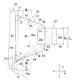
着用物品の一例として示す、使い捨ておむつの部分破断平面図。
図1の部分拡大図。
図2のIII-III線拡大断面図。
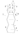
弾性シートに内側弾性体と外側弾性体を取り付ける工程の一例を示す図。
実施態様の一例を示す図3と同様な図。
実施態様の一例を示す図3と同様な図。
実施態様の一例を示す図2と同様な図。
下記の実施の形態は、図1~7に示す着用物品に関し、発明の不可欠な構成とともに、選択的および好ましい構成を含む。
この発明に係る着用物品として使い捨ておむつを例にとり、この発明の詳細を説明すると、以下のとおりである。
図1を参照すると、おむつ1は開放型のものであって、ほぼ矩形のシャシー20を有する。シャシー20は、透液性身体側ライナー2と、不透液性外カバー3とを有し、これらの間に介在する吸収体10とを含む。身体側ライナー2および外カバー3は、吸収体10の周縁から延出する部分において重なり合い、例えばホットメルト接着剤(図示せず)を介して互いに接合されている。おむつ1の横方向と縦方向とは、双頭矢印X,Yで示される。シャシー20は、その縦方向Yにおいて、前ウエスト域6と、後ウエスト域7と、これら両域6,7の間に介在するクロッチ域8とを有する。前ウエスト域6と後ウエスト域7とには、横方向Xへ延びるテープ状のウエスト弾性体11,12が身体側ライナー2と外カバー3との間にあって、これらの少なくとも一方に伸長状態で収縮可能に固定される。クロッチ域8には、シャシー20の側縁部21に沿って縦方向Yへ延びる複数条のレッグ弾性体13が身体側ライナー2と外カバー3との間に介在し、これらの少なくとも一方に伸長状態で収縮可能に固定される。好ましいシャシー20において、レッグ弾性体13は前後ウエスト域6,7のうちの少なくとも後ウエスト域7に達する。
図1を併せて図2を参照すると、シャシー20における後ウエスト域7の側縁部21からは、サイドパネル30が横方向Xへ延出する。サイドパネル30は、縦方向Yにおける中央域45が横方向Xに弾性を有する。例えば弾性パネル材料31から形成される。サイドパネル30はまた、中央域45に加えて、近位縁部32と、遠位縁部33と、内側縁部34と、外側縁部36とを有し、近位縁部32と遠位縁部33とが縦方向Yへ延びる一方、内側縁部34と外側縁部36とは近位縁部32と遠位縁部33との間に互いに外に向かって近寄るように延びる。近位縁部32は、外カバー3と後記バリヤーカフ16との間にあり、ホットメルト接着剤17を介してこれら3,16に接合される。内側縁部34と外側縁部36とは、中央域45を形成する弾性パネル材料31が縦方向Yへの拡張部分によって形成される。おむつ1はファスナアッセンブリ37を含み、ファスナアッセンブリ37は、弾性パネル材料31に取り付けられるテープタブ38と、留付部39とを含む。テープタブ38は例えば非伸長性の繊維不織布やプラスチックフィルムで形成され、固定域38aと延出域38bとを有する。固定域38aは、例えばホットメルト接着剤等の接合手段(図示せず)を介してサイドパネル30に剥離不能に接合される。延出域38bは、遠位縁部33から横方向Xに延出していて摘持可能であって、その内面に留付部39が固定されている。留付部39は、前ウエスト域6の外面に設けられたターゲット域(図示せず)またはそれに代わる適宜の部位に対して剥離可能に留付けられ、商品名ベルクロ(登録商標)等で知られる例えばメカニカルファスナのフック要素または粘着剤によって形成される。
シャシー20の各側縁部21のそれぞれは、バリヤーカフ16が縦方向Yに延びている。バリヤーカフ16は、例えば撥水性、より好ましくは撥水性を有する背に不織布などのシート材料から形成され、互いに並行する外近位縁部16aと遠位縁部16b、および互いに並行する前端縁部16cと後端縁部16dを有する。近位縁部16aと前端縁部16cと後端縁部16dとは、例えばホットメルト接着剤17を介してシャシー20に接合される。遠位縁部16bは、縦方向Yのうちの少なくともクロッチ域8においてはシャシー20に接合されない。遠位縁部16bはまたスリーブ18を有し、スリーブ18の内側にはスペース手段としての糸・ストランドまたはストリング状の弾性体19が例えばホットメルト接着剤(図示せず)を介して伸長状態で収縮可能に固定されている。かようなバリヤーカフ16は、おむつ1が着用されてシャシー20が身体側ライナー2を内側にしてほぼU字形に湾曲すると、伸長状態にあった弾性体19が収縮して、遠位縁部16bが身体側ライナー2から離間し、身体側ライナー2に対してバリヤーカフ16が起ち上がって、身体側ライナー2とバリヤーカフ16との間にスペースが画定され、身体側ライナー2の上に排泄される排泄物を封じ込める機能を有する。
再び、図2を参照すると、サイドパネル30は、近位縁部32から横方向Xへ延びる内側縁部34が近位縁部32と交角αで交わり、外側縁部36が近位縁部32と交角βで交わる。交角α,βは例えば50-80°の範囲にあり、好ましいサイドパネル30では、交角αと交角βとが等しい。また、近位縁部32の縦方向Yにおける寸法は40-130mmの範囲にあり、遠位縁部33の縦方向Yにおける寸法は20-100mmの範囲にあることが好ましい。交角α,βが50°よりも小さいと、サイドパネル30に作用させる横方向Xの引張り力によってウエスト弾性体12をウエスト回り方向へ引張るということが難しい。また、交角α,βが80°よりも大きいと、サイドパネル30が必要以上に大きなものになることがある。サイドパネル30の延出方向における内側縁部34と外側縁部36との寸法は、近位縁部32と遠位縁部33との前記寸法と交角α,βの大きさとによって決まる値であるが、好ましいサイドパネル30では、内側縁部34と外側縁部36とが同じ寸法を有する。したがって、この発明の一つの実施の形態における好ましいサイドパネル30の平面視形状は等脚台形である。また、好ましいサイドパネル30とシャシー20とでは、ウエスト回り方向へ引張られるファスナアッセンブリ37の固定域38aが、仮想線46,47で示すように、サイドパネル30を介してシャシー20におけるレッグ弾性体13をおむつ着用者の身体の上方に向かって引き上げるように力を作用させ、そのおむつ1のずり下がりを防ぐことができる。仮想線46,47は、サイドパネル30の近位縁部32をシャシー20とバリヤーカフ16とに対して接合される接合部48の内端部分50とファスナアッセンブリ37の固定域38aにおける内側縁部38cとを結ぶ線であって、後ウエスト域7に向かって延びるレッグ弾性体13と交差する。
図3を参照すると、サイドパネル30を形成する弾性パネル材料31が内側縁部34と外側縁部36とに沿っておむつ1の外側に向かって折曲され、それぞれの折曲部分の内部に内側が弾性体51および外側弾性体52が介在することにより、内側重層部41と外側重層部42とが形成される。ここでいう重層部とは、サイドパネル30の中央域45を形成している弾性パネル材料31の縦方向Yにおける拡張部分である内側縁部34および外側縁部36に対して弾性パネル材料31とは別体の材料、例えば内側弾性体41や外側弾性体42が重なることを意味している。そのような内側重層部41と外側重層部42とのそれぞれでは、例えばホットメルト接着剤43を介して弾性パネル材料31を互いに、および弾性パネル材料31と糸・ストランドまたはストリング状の内側弾性体51および糸・ストランドまたはストリング状の外側弾性体52のそれぞれとが接合される。内側弾性体51と外側弾性体52とは、内側縁部34と外側縁部36とにおいての弾性パネル材料31に対する追加の材料であって、糸状やリボン状等の形態をとることができ、近位縁部32と遠位縁部33との間において伸長状態または非伸長状態で延びる。伸長状態にある弾性体51や52は、それらの弾性率にもよるが、伸長率が好ましくは3.5倍以下、より好ましくは2.5倍以下、さらに好ましくは1.5倍以下に抑えられると、内側縁部34や外側縁部36を過度に収縮させることがない。内側縁部34が延びる方向と直交する方向において測定される内側重層部41の幅W1と、外側縁部36が延びる方向と直交する方向において測定される外側重層部42の幅W2とは(図2参照)、約3-15mmの範囲にある。弾性パネル材料31には、例えばポリエチレン繊維やポリプロピレン繊維とポリウレタン繊維とを含む弾性的に伸長可能な不織布、ポリウレタン繊維で形成された弾性的に伸長可能な不織布、ポリウレタンフィルムの如き弾性的に伸長可能なフィルム等を使用することができる。
再び図2において、サイドパネル30における遠位縁部33にはファスナアッセンブリ37における固定域38aが接着剤やエンボス/デボス加工等の接合手段(図示せず)を使用して取り付けられる。ファスナアッセンブリ37は、縦方向Yに幅W3を有し、その幅W3は、遠位縁部33における内側重層部41と外側重層部42との離間寸法D1よりも小さく、内側重層部41と外側重層部42とに重なることがないようにサイドパネル30に取り付けられている。好ましいファスナアッセンブリ37は、離間寸法D1を有する遠位縁部33の中央部分またはその中央部分から後方に寄った位置においてサイドパネル30に取り付けられる。
おむつ1を着用するときには、前後ウエスト域6,7を着用者のウエスト回りにあてがってファスナアッセンブリ37の延出域38bを摘持し、サイドパネル30をウエスト回りに沿って引張りながら留付部39を前ウエスト域6におけるターゲットゾーン等の所要部位に留付ける。このときのサイドパネル30は、それを図2のサイドパネル30でみると、弾性パネル材料31のうちで固定域38aの延長上に位置するサイドパネル30の縦方向Yにおける中央域45が図2における横方向Xへ引張られ、伸長することに相当する。一方、サイドパネル30の内側縁部34と外側縁部36とは、折り重ねられた弾性パネル材料31の存在と追加の材料である内側弾性体51および外側弾性体52の存在とによって変形しにくい状態にあり、しわが生じたり、折れ曲がったり、サイドパネル30の外面側に向かって反り返ったりするということが生じにくい。それゆえ、着用後のおむつ1の外面をみると、サイドパネル30の存在する域は比較的に平滑で、おむつ1の外観を損ねるということがない。
また、おむつ1を着用しているときに、変形しにくい外側縁部36は、ファスナアッセンブリ37に作用するウエスト回り方向の張力を後ウエスト域7の弾性体12に作用させて、後ウエスト域7を着用者に密着させるようにも作用する。
さらにはまた、着用状態にあるおむつ1では、ファスナアッセンブリ37が引張られることに伴って、固定域38aの内側縁部38cがシャシー20におけるレッグ弾性体13をおむつ着用者の身体の上方に向かって引き上げるように力を作用させ、既述のように、おむつ1のずり下がりを防ぐことができる。なお、この発明において、内側弾性体51および/または外側弾性体52を、サイドパネル30の内面に取り付けて、弾性パネル材料31によってサンドウィッチすることもできる。
図4は、図2,3に例示の内側弾性体51と外側弾性体52とを弾性パネル材料31に取り付ける方法の一例を示す図である。図に示された機械方向MDには、弾性パネル材料31のウエブ300が走行している。機械方向MDの上流側には、双頭矢印Fで示されている方向へ往復旋回運動をする第1アーム301と第2アーム302とが配置されている。それぞれのアーム301,302における先端のガイド孔301a,302aには、糸・ストランドまたはストリング状の第1連続弾性体351と糸・ストランドまたはストリング状の第2連続弾性体352とが所要の伸長率と所要の速度とで供給される。ウエブ300および/または第1,第2連続弾性体351,352は、図示されていない工程で予めホットメルト接着剤が塗布される。第1,第2アーム301,302は、旋回しながら第1,第2連続弾性体351,352をウエブ300の所要部位に供給することによって、第1,第2連続弾性体351,352が所要のパターンの起伏を繰り返している図示例の複合ウエブ310が得られる。複合ウエブ310では、第1,第2連続弾性体351,352のそれぞれを被覆するために、仮想線で示す折曲案内線305に沿ってウエブ300を折り重ね、互いに接合する。しかる後に交差方向CDへ伸びるカットラインCに沿って複合ウエブ310を切断することによって、シャシー20に取り付けることのできる一対の前記サイドパネル30を得ることができる。そのサイドパネル30には、適宜の工程においてファスナアッセンブリ37を取り付ける。
図5を参照するとこれは、実施態様の一例を示す図3と同様な図であって、図5におけるサイドパネル30では、弾性パネル材料31に対する追加の材料として内側縁部34の外面側に内側弾性体51と細長い弾性被覆シート53とがホットメルト接着剤43を介して取り付けられ、内側重層部41が形成される一方、もう一つの追加の材料として外側縁部36の外面側に外側弾性体52と弾性被覆シート54とがホットメルト接着剤43を介して取り付けられ、外側重層部42が形成される。これら内側弾性体51、弾性被覆シート53、外側弾性体52、弾性被覆シート54は、近位縁部32と遠位縁部33との間に伸長状態または非伸長状態で延びている。内側弾性体51と外側弾性体52とは、このように弾性パネル材料31とは別体の弾性被覆シート53や弾性被覆シート54によって被覆したり、必要ならば弾性パネル材料31とは別体であるだけではなくて、弾性パネル材料31とは弾性率の異なる弾性被覆シート53や弾性被覆シート54によって被覆したりすることができる。この発明において、図4の実施態様は、内側弾性体51と外側弾性体52とのうちの一方を使用することのない態様に変更させることもできる。内側弾性体51および外側弾性体52は、サイドパネル30の内面に取り付けることもできる。
図6を参照するとこれもまた、実施態様の一例を示す図5と同様な図である。サイドパネル30における内側縁部34の外面には、弾性パネル材料31に対する追加の材料として、内側弾性体51と弾性被覆シート53とに替わる帯状の弾性裏打ちシート55がホットメルト接着剤43を介して取り付けられて内側重層部41が形成され、外側縁部36には、弾性パネル材料31に対する追加の材料として、外側弾性体52と弾性被覆シート43とに替わる帯状の弾性裏打ちシート56がホットメルト接着剤43を介して取り付けられ外側重層部42が形成される。これらの弾性裏打ちシート55,56は、近位縁部32と遠位縁部33との間に伸長状態または非伸長状態で延びる。弾性裏打ちシート55,56には、弾性パネル材料31とは異なる弾性率を有するパネル材料を使用することができる。また、弾性裏打ちシート55,56のうちの少なくとも一方をサイドパネル30の内面に取り付けることもできる。
図7を参照すると、これもまた、実施態様の一例を示す図2と同様な図であるが、部材の一部が破断した状態で示されている。図7のサイドパネル30の内面では、弾性パネル材料31に対する追加の材料として、シート状の弾性部材である内側弾性シート57と外側弾性シート58とが非伸長状態でホットメルト接着剤43を介して取り付けられることによって、内側重層部41と外側重層部42とが形成される。内側弾性シート57は内側縁部34とファスナアッセンブリ37との間、より詳しくは内側縁部34と中央域45との間にあり、外側弾性シート58は外側縁部36とファスナアッセンブリ37との間、より詳しくは外側縁部36と中央域45との間にある。このように形成されるサイドパネル30もまた、ファスナアッセンブリ37が横方向Xへ引張られると、中央域45が容易に弾性的に伸長する一方、内側縁部34と中央域45との間の部分である内側重層部41、および外側縁部36と中央域46との間の部分である外側重層部42が伸長しにくい部分となって内側縁部34や外側縁部36の変形を抑えることができる。内側弾性シート57と外側弾性シート58とは、弾性率が弾性パネル材料31のそれと同じであってもよいし、異なっていてもよい。
この発明において、サイドパネル30が弾性的に伸長と収縮とを反復することができるものである場合、内側縁部34、外側縁部36、中央域45の弾性的な伸び易さ、伸びにくさを比較するのには、次のようにする。すなわち、内側縁部34と外側縁部36とについては、それぞれが延びる方向と直交する方向の幅が5mm、平行する方向の長さが40mmの試片を採取する。また、中央域45については縦方向Yの幅が5mm、横方向Xの長さが40mmの試片を採取する。これらの試片について、引張試験機のチャック間隔が20mmとなるように引張試験機にセットする。引張速度を50mm/minに設定し、伸長率が20%であるときに、各試片に生じた応力を比較して、応力の小さい方の試片を延びやすいものと判断する。なお、この発明において、弾性的に伸びるというときには、試片を20%伸長後に、その伸長から解放した試片の長さが1分以内に元の長さの1.05倍以下になることを意味する。
この発明においてはまた、サイドパネル30について、図示例の伸長と収縮との反復が可能な弾性パネル材料31に替えて、非伸長性のパネル材料を使用することもできる。ポリエチレン繊維やポリプロピレン繊維、ポリエステル繊維等で形成されていて、実質的な意味において非伸長性であるポイントボンド不織布、スパンボンド不織布、スパンレース不織布、これら不織布の積層体等を使用することができる他に、非伸長性のプラスチックフィルムを使用することもできる。これら非伸長性のシートに対して使用される追加の材料は、図示例の内側弾性体51や外側弾性体52の如き伸長と収縮とを反復することのできる弾性材料であってもよいし、伸長と収縮とを反復することのできない非弾性的な材料であってもよい。
以上のこの発明に関する開示は、少なくとも下記事項に整理することができる。
この発明は、互いに直交する縦方向と横方向とを有し、前ウエスト域と後ウエスト域とクロッチ域とを有するシャシーと、前記シャシーの両側縁部から延出し、近位縁部と、遠位縁部と、内側縁部と、外側縁部と、前記内外側縁部の間の中央域とを有するサイドパネルと、前記サイドパネルの前記遠位縁部に位置し前記前後ウエスト域を互いに連結するためのファスナアッセンブリとを含む着用物品であって、
前記サイドパネルは、前記内側縁部と前記外側縁部との前記縦方向における離間寸法が前記近位縁部から前記遠位縁部に向かって次第に小さくなっており、
前記内側縁部と前記外側縁部とが、前記内側縁部と、前記外側縁部に沿って延びる拡張部分と、前記拡張部分に接合する前記拡張部分とは別体である追加の材料とによって形成されていることを特徴とする。
この発明は、互いに直交する縦方向と横方向とを有し、前ウエスト域と後ウエスト域とクロッチ域とを有するシャシーと、前記シャシーの両側縁部から延出し、近位縁部と、遠位縁部と、内側縁部と、外側縁部と、前記内外側縁部の間の中央域とを有するサイドパネルと、前記サイドパネルの前記遠位縁部に位置し前記前後ウエスト域を互いに連結するためのファスナアッセンブリとを含む着用物品であって、
前記サイドパネルは、前記内側縁部と前記外側縁部との前記縦方向における離間寸法が前記近位縁部から前記遠位縁部に向かって次第に小さくなっており、
前記内側縁部と前記外側縁部とが、前記内側縁部と、前記外側縁部に沿って延びる拡張部分と、前記拡張部分に接合する前記拡張部分とは別体である追加の材料とによって形成されていることを特徴とする。
この発明は、少なくとも下記の実施の形態を含み、該実施の形態は、互いに分離しまたは組み合わせて採択される。
(1)前記追加の材料が、前記内側縁部と前記外側縁部に沿って伸長状態および非伸長状態のいずれかの状態で延びる弾性材料である。
(2)前記追加の材料が、糸・ストランドまたはストリング状のものおよびリボン状のもののいずれかである。
(3)前記追加の材料が、前記内側縁部と前記外側縁部において折り重ねられている前記拡張部分によってサンドウィッチされている。
(4)前記ファスナアッセンブリが、前記縦方向において前記内側縁部と前記外側縁部との間に位置し、前記追加の材料が、前記縦方向において、前記内側縁部と前記ファスナアッセンブリとの間、および前記外側縁部と前記ファスナアッセンブリとの間のうちの少なくとも一方に広がるシート状のものである。
(5)前記サイドパネルは、台形を有し、前記遠位縁部が前記縦方向へ延びて前記近位縁部に平行し、前記内側縁部と前記外側縁部とは長さが等しくかつ前記近位縁部との交角が等しい。
(6)前記ファスナアッセンブリは、前記遠位縁部に接合する固定域と前記遠位縁部から前記横方向へ延びる延出域とを有するテープタブと、前記延出域にあって前記前ウエスト域の所要部位に対して離脱可能な留付部とを含み、前記固定域が前記内側縁部と前記外側縁部との間に位置し、かつ、前記追加の材料と重なることがないように前記遠位縁部に接合する。
(7)前記ファスナアッセンブリは、前記折り重ねられている前記拡張部分と重なることがないように前記固定域が前記遠位縁部に接合する。
(8)前記シャシーは、前記両側縁部に前記縦方向へ伸長状態で延びるレッグ弾性体を有し、前記ファスナアッセンブリにおける前記固定域の内側縁部と前記近位縁部における前記接合部の内端部分とを結ぶ線の延長線が前記レッグ弾性体と交差する。
(9)前記サイドパネルの前記中央域を形成しているパネル材料が、前記横方向において伸長と収縮との反復が可能である弾性材料および前記反復が不能である非弾性シートの一つである。
(1)前記追加の材料が、前記内側縁部と前記外側縁部に沿って伸長状態および非伸長状態のいずれかの状態で延びる弾性材料である。
(2)前記追加の材料が、糸・ストランドまたはストリング状のものおよびリボン状のもののいずれかである。
(3)前記追加の材料が、前記内側縁部と前記外側縁部において折り重ねられている前記拡張部分によってサンドウィッチされている。
(4)前記ファスナアッセンブリが、前記縦方向において前記内側縁部と前記外側縁部との間に位置し、前記追加の材料が、前記縦方向において、前記内側縁部と前記ファスナアッセンブリとの間、および前記外側縁部と前記ファスナアッセンブリとの間のうちの少なくとも一方に広がるシート状のものである。
(5)前記サイドパネルは、台形を有し、前記遠位縁部が前記縦方向へ延びて前記近位縁部に平行し、前記内側縁部と前記外側縁部とは長さが等しくかつ前記近位縁部との交角が等しい。
(6)前記ファスナアッセンブリは、前記遠位縁部に接合する固定域と前記遠位縁部から前記横方向へ延びる延出域とを有するテープタブと、前記延出域にあって前記前ウエスト域の所要部位に対して離脱可能な留付部とを含み、前記固定域が前記内側縁部と前記外側縁部との間に位置し、かつ、前記追加の材料と重なることがないように前記遠位縁部に接合する。
(7)前記ファスナアッセンブリは、前記折り重ねられている前記拡張部分と重なることがないように前記固定域が前記遠位縁部に接合する。
(8)前記シャシーは、前記両側縁部に前記縦方向へ伸長状態で延びるレッグ弾性体を有し、前記ファスナアッセンブリにおける前記固定域の内側縁部と前記近位縁部における前記接合部の内端部分とを結ぶ線の延長線が前記レッグ弾性体と交差する。
(9)前記サイドパネルの前記中央域を形成しているパネル材料が、前記横方向において伸長と収縮との反復が可能である弾性材料および前記反復が不能である非弾性シートの一つである。
1 着用物品(おむつ)
6 前ウエスト域
7 後ウエスト域
8 クロッチ域
13 レッグ弾性体
20 シャシー
21 側縁部
30 サイドパネル
31 弾性パネル材料
32 近位縁部
33 遠位縁部
34 内側縁部(拡張部分)
36 外側縁部(拡張部分)
37 ファスナアッセンブリ
38 テープタブ
38a 固定域
38b 延出域
38c 内側縁部
39 留付部
45 中央域
46 線
47 線
48 接合部
50 内側部分
51,52,53,54,55,56,57,58 追加の材料(弾性体)
W3 離間寸法
X 横方向
Y 縦方向
α 交角
β 交角
6 前ウエスト域
7 後ウエスト域
8 クロッチ域
13 レッグ弾性体
20 シャシー
21 側縁部
30 サイドパネル
31 弾性パネル材料
32 近位縁部
33 遠位縁部
34 内側縁部(拡張部分)
36 外側縁部(拡張部分)
37 ファスナアッセンブリ
38 テープタブ
38a 固定域
38b 延出域
38c 内側縁部
39 留付部
45 中央域
46 線
47 線
48 接合部
50 内側部分
51,52,53,54,55,56,57,58 追加の材料(弾性体)
W3 離間寸法
X 横方向
Y 縦方向
α 交角
β 交角
Claims (10)
- 互いに直交する縦方向と横方向とを有し、前ウエスト域と後ウエスト域とクロッチ域とを有するシャシーと、前記シャシーの両側縁部から延出し、近位縁部と、遠位縁部と、内側縁部と、外側縁部と、前記内外側縁部の間の中央域とを有するサイドパネルと、前記サイドパネルの前記遠位縁部に位置し前記前後ウエスト域を互いに連結するためのファスナアッセンブリとを含む着用物品であって、
前記サイドパネルは、前記内側縁部と前記外側縁部との前記縦方向における離間寸法が前記近位縁部から前記遠位縁部に向かって次第に小さくなっており、
前記内側縁部と前記外側縁部とが、前記内側縁部と、前記外側縁部に沿って延びる拡張部分と、前記拡張部分に接合する前記拡張部分とは別体である追加の材料とによって形成されていることを特徴とする前記着用物品。 - 前記追加の材料が、前記内側縁部と前記外側縁部に沿って伸長状態および非伸長状態のいずれかの状態で延びる弾性材料である請求項1記載の着用物品。
- 前記追加の材料が、糸・ストランドまたはストリング状のものおよびリボン状のもののいずれかである請求項1または2記載の着用物品。
- 前記追加の材料が、前記内側縁部と前記外側縁部において折り重ねられている前記拡張部分によってサンドウィッチされている請求項1-3のいずれかに記載の着用物品。
- 前記ファスナアッセンブリが、前記縦方向において前記内側縁部と前記外側縁部との間に位置し、前記追加の材料が、前記縦方向において、前記内側縁部と前記ファスナアッセンブリとの間、および前記外側縁部と前記ファスナアッセンブリとの間のうちの少なくとも一方に広がるシート状のものである請求項1記載の着用物品。
- 前記サイドパネルは、台形を有し、前記遠位縁部が前記縦方向へ延びて前記近位縁部に平行し、前記内側縁部と前記外側縁部とは長さが等しくかつ前記近位縁部との交角が等しい請求項1-5のいずれかに記載の着用物品。
- 前記ファスナアッセンブリは、前記遠位縁部に接合する固定域と前記遠位縁部から前記横方向へ延びる延出域とを有するテープタブと、前記延出域にあって前記前ウエスト域の所要部位に対して離脱可能な留付部とを含み、前記固定域が前記内側縁部と前記外側縁部との間に位置し、かつ、前記追加の材料と重なることがないように前記遠位縁部に接合する請求項1-6のいずれかに記載の着用物品。
- 前記ファスナアッセンブリは、前記折り重ねられている前記拡張部分と重なることがないように前記固定域が前記遠位縁部に接合する請求項7記載の着用物品。
- 前記シャシーは、前記両側縁部に前記縦方向へ伸長状態で延びるレッグ弾性体を有し、前記ファスナアッセンブリにおける前記固定域の内側縁部と前記近位縁部における前記接合部の内端部分とを結ぶ線の延長線が前記レッグ弾性体と交差する請求項7または8記載の着用物品。
- 前記サイドパネルの前記中央域を形成しているパネル材料が、前記横方向において伸長と収縮との反復が可能である弾性材料および前記反復が不能である非弾性シートの一つである請求項1-9のいずれかに記載の着用物品。
Priority Applications (1)
| Application Number | Priority Date | Filing Date | Title |
|---|---|---|---|
| SA515360234A SA515360234B1 (ar) | 2012-10-02 | 2015-04-02 | منتج ارتداء يستخدم لمره واحدة |
Applications Claiming Priority (2)
| Application Number | Priority Date | Filing Date | Title |
|---|---|---|---|
| JP2012-222392 | 2012-10-04 | ||
| JP2012222392A JP2014073251A (ja) | 2012-10-04 | 2012-10-04 | 着用物品 |
Publications (1)
| Publication Number | Publication Date |
|---|---|
| WO2014054436A1 true WO2014054436A1 (ja) | 2014-04-10 |
Family
ID=50434766
Family Applications (1)
| Application Number | Title | Priority Date | Filing Date |
|---|---|---|---|
| PCT/JP2013/075457 Ceased WO2014054436A1 (ja) | 2012-10-02 | 2013-09-20 | 着用物品 |
Country Status (3)
| Country | Link |
|---|---|
| JP (1) | JP2014073251A (ja) |
| SA (1) | SA515360234B1 (ja) |
| WO (1) | WO2014054436A1 (ja) |
Citations (3)
| Publication number | Priority date | Publication date | Assignee | Title |
|---|---|---|---|---|
| JPH08191860A (ja) * | 1995-01-11 | 1996-07-30 | Procter & Gamble Co:The | 使い捨ておむつ |
| JP2004174210A (ja) * | 2002-09-30 | 2004-06-24 | Uni Charm Corp | 使い捨てオムツ |
| JP2010227509A (ja) * | 2009-03-30 | 2010-10-14 | Daio Paper Corp | 吸収性物品 |
Family Cites Families (2)
| Publication number | Priority date | Publication date | Assignee | Title |
|---|---|---|---|---|
| JP2003153955A (ja) * | 2001-11-22 | 2003-05-27 | Uni Charm Corp | 開放型の使い捨ておむつ |
| JP5328168B2 (ja) * | 2008-02-04 | 2013-10-30 | ユニ・チャーム株式会社 | 着用物品 |
-
2012
- 2012-10-04 JP JP2012222392A patent/JP2014073251A/ja active Pending
-
2013
- 2013-09-20 WO PCT/JP2013/075457 patent/WO2014054436A1/ja not_active Ceased
-
2015
- 2015-04-02 SA SA515360234A patent/SA515360234B1/ar unknown
Patent Citations (3)
| Publication number | Priority date | Publication date | Assignee | Title |
|---|---|---|---|---|
| JPH08191860A (ja) * | 1995-01-11 | 1996-07-30 | Procter & Gamble Co:The | 使い捨ておむつ |
| JP2004174210A (ja) * | 2002-09-30 | 2004-06-24 | Uni Charm Corp | 使い捨てオムツ |
| JP2010227509A (ja) * | 2009-03-30 | 2010-10-14 | Daio Paper Corp | 吸収性物品 |
Also Published As
| Publication number | Publication date |
|---|---|
| SA515360234B1 (ar) | 2017-04-03 |
| JP2014073251A (ja) | 2014-04-24 |
Similar Documents
| Publication | Publication Date | Title |
|---|---|---|
| TWI241907B (en) | Disposable absorbent article and method of producing the same | |
| RU2580990C2 (ru) | Подгузник одноразового использования и способ его изготовления | |
| JP6473327B2 (ja) | 吸収性物品 | |
| RU2570498C1 (ru) | Впитывающее изделие типа трусов | |
| EP2891479B1 (en) | Pull-on clothing article | |
| KR101395437B1 (ko) | 성인용 기저귀 | |
| JP2013188379A (ja) | パンツタイプ使い捨ておむつ及びその製造方法 | |
| CN107847370B (zh) | 一次性穿着物品 | |
| CN111971013A (zh) | 短裤型一次性尿布 | |
| JP5306889B2 (ja) | 着用物品 | |
| WO2014073648A1 (ja) | 使い捨ておむつ | |
| JP6278710B2 (ja) | 使い捨てのパンツ型着用物品 | |
| WO2014054436A1 (ja) | 着用物品 | |
| WO2013047152A1 (ja) | 使い捨ておむつ | |
| JP6453146B2 (ja) | 使い捨て着用物品 | |
| JP6436771B2 (ja) | 使い捨ての着用物品 | |
| JP6080467B2 (ja) | 着用物品 | |
| JP5638314B2 (ja) | 吸収性物品 | |
| JP6453145B2 (ja) | 使い捨ての着用物品 | |
| WO2019123572A1 (ja) | 吸収性物品 | |
| WO2017029998A1 (ja) | 使い捨て着用物品及び使い捨て着用物品の製造方法 | |
| JP6495710B2 (ja) | 使い捨て着用物品 | |
| JP3211618U (ja) | パンツ型着用物品 | |
| JP2014217583A (ja) | パンツ型着用物品 | |
| JP2013027647A (ja) | 吸収性物品 |
Legal Events
| Date | Code | Title | Description |
|---|---|---|---|
| 121 | Ep: the epo has been informed by wipo that ep was designated in this application |
Ref document number: 13843182 Country of ref document: EP Kind code of ref document: A1 |
|
| NENP | Non-entry into the national phase |
Ref country code: DE |
|
| 122 | Ep: pct application non-entry in european phase |
Ref document number: 13843182 Country of ref document: EP Kind code of ref document: A1 |