WO2014050997A1 - 分離モジュール、分離システム及び分離システム群 - Google Patents
分離モジュール、分離システム及び分離システム群 Download PDFInfo
- Publication number
- WO2014050997A1 WO2014050997A1 PCT/JP2013/076129 JP2013076129W WO2014050997A1 WO 2014050997 A1 WO2014050997 A1 WO 2014050997A1 JP 2013076129 W JP2013076129 W JP 2013076129W WO 2014050997 A1 WO2014050997 A1 WO 2014050997A1
- Authority
- WO
- WIPO (PCT)
- Prior art keywords
- gas
- separation
- flow path
- separation module
- supply
- Prior art date
- Legal status (The legal status is an assumption and is not a legal conclusion. Google has not performed a legal analysis and makes no representation as to the accuracy of the status listed.)
- Ceased
Links
Images








Classifications
-
- B—PERFORMING OPERATIONS; TRANSPORTING
- B01—PHYSICAL OR CHEMICAL PROCESSES OR APPARATUS IN GENERAL
- B01D—SEPARATION
- B01D53/00—Separation of gases or vapours; Recovering vapours of volatile solvents from gases; Chemical or biological purification of waste gases, e.g. engine exhaust gases, smoke, fumes, flue gases, aerosols
- B01D53/22—Separation of gases or vapours; Recovering vapours of volatile solvents from gases; Chemical or biological purification of waste gases, e.g. engine exhaust gases, smoke, fumes, flue gases, aerosols by diffusion
-
- B—PERFORMING OPERATIONS; TRANSPORTING
- B01—PHYSICAL OR CHEMICAL PROCESSES OR APPARATUS IN GENERAL
- B01D—SEPARATION
- B01D53/00—Separation of gases or vapours; Recovering vapours of volatile solvents from gases; Chemical or biological purification of waste gases, e.g. engine exhaust gases, smoke, fumes, flue gases, aerosols
- B01D53/02—Separation of gases or vapours; Recovering vapours of volatile solvents from gases; Chemical or biological purification of waste gases, e.g. engine exhaust gases, smoke, fumes, flue gases, aerosols by adsorption, e.g. preparative gas chromatography
- B01D53/04—Separation of gases or vapours; Recovering vapours of volatile solvents from gases; Chemical or biological purification of waste gases, e.g. engine exhaust gases, smoke, fumes, flue gases, aerosols by adsorption, e.g. preparative gas chromatography with stationary adsorbents
- B01D53/0407—Constructional details of adsorbing systems
- B01D53/0446—Means for feeding or distributing gases
-
- B—PERFORMING OPERATIONS; TRANSPORTING
- B01—PHYSICAL OR CHEMICAL PROCESSES OR APPARATUS IN GENERAL
- B01D—SEPARATION
- B01D53/00—Separation of gases or vapours; Recovering vapours of volatile solvents from gases; Chemical or biological purification of waste gases, e.g. engine exhaust gases, smoke, fumes, flue gases, aerosols
- B01D53/22—Separation of gases or vapours; Recovering vapours of volatile solvents from gases; Chemical or biological purification of waste gases, e.g. engine exhaust gases, smoke, fumes, flue gases, aerosols by diffusion
- B01D53/225—Multiple stage diffusion
- B01D53/226—Multiple stage diffusion in serial connexion
-
- B—PERFORMING OPERATIONS; TRANSPORTING
- B01—PHYSICAL OR CHEMICAL PROCESSES OR APPARATUS IN GENERAL
- B01D—SEPARATION
- B01D63/00—Apparatus in general for separation processes using semi-permeable membranes
- B01D63/10—Spiral-wound membrane modules
- B01D63/101—Spiral winding
-
- B—PERFORMING OPERATIONS; TRANSPORTING
- B01—PHYSICAL OR CHEMICAL PROCESSES OR APPARATUS IN GENERAL
- B01D—SEPARATION
- B01D2256/00—Main component in the product gas stream after treatment
- B01D2256/16—Hydrogen
-
- B—PERFORMING OPERATIONS; TRANSPORTING
- B01—PHYSICAL OR CHEMICAL PROCESSES OR APPARATUS IN GENERAL
- B01D—SEPARATION
- B01D2257/00—Components to be removed
- B01D2257/50—Carbon oxides
- B01D2257/504—Carbon dioxide
-
- B—PERFORMING OPERATIONS; TRANSPORTING
- B01—PHYSICAL OR CHEMICAL PROCESSES OR APPARATUS IN GENERAL
- B01D—SEPARATION
- B01D2259/00—Type of treatment
- B01D2259/40—Further details for adsorption processes and devices
- B01D2259/41—Further details for adsorption processes and devices using plural beds of the same adsorbent in series
-
- B—PERFORMING OPERATIONS; TRANSPORTING
- B01—PHYSICAL OR CHEMICAL PROCESSES OR APPARATUS IN GENERAL
- B01D—SEPARATION
- B01D2311/00—Details relating to membrane separation process operations and control
- B01D2311/13—Use of sweep gas
-
- B—PERFORMING OPERATIONS; TRANSPORTING
- B01—PHYSICAL OR CHEMICAL PROCESSES OR APPARATUS IN GENERAL
- B01D—SEPARATION
- B01D2313/00—Details relating to membrane modules or apparatus
- B01D2313/23—Specific membrane protectors, e.g. sleeves or screens
-
- Y—GENERAL TAGGING OF NEW TECHNOLOGICAL DEVELOPMENTS; GENERAL TAGGING OF CROSS-SECTIONAL TECHNOLOGIES SPANNING OVER SEVERAL SECTIONS OF THE IPC; TECHNICAL SUBJECTS COVERED BY FORMER USPC CROSS-REFERENCE ART COLLECTIONS [XRACs] AND DIGESTS
- Y02—TECHNOLOGIES OR APPLICATIONS FOR MITIGATION OR ADAPTATION AGAINST CLIMATE CHANGE
- Y02C—CAPTURE, STORAGE, SEQUESTRATION OR DISPOSAL OF GREENHOUSE GASES [GHG]
- Y02C20/00—Capture or disposal of greenhouse gases
- Y02C20/40—Capture or disposal of greenhouse gases of CO2
Definitions
- the present invention relates to a separation module, a separation system, and a separation system group.
- Japanese Patent Laid-Open No. 5-131123 discloses a separation member that permeates and separates a gas component in a supplied gas, and a permeating gas passage member that serves as a passage for the gas component that has permeated the separation member.
- a separation module is disclosed in which a laminated body including a wound body is wound around a tubular body having a through-hole formed on an outer peripheral surface, and the wound laminated body is covered with a covering member.
- both ends in the width direction and the winding end of the permeate gas flow path member are sealed with an adhesive, and the gas component that has permeated the separation member flows through the permeate gas flow path member and passes through the hole. It is going to go to.
- a sweep gas is caused to flow from the tube body into the permeate gas flow path member through the through hole.
- the present invention has been made in view of the above circumstances, and an object thereof is to provide a separation module, a separation system, and a separation system group having high separation efficiency of gas components.
- the separation module according to the first aspect of the present invention includes a tubular body having a through-hole formed on an outer peripheral surface, a supply gas passage member to which a gas is supplied, and the gas that passes through the supply gas passage member.
- a covering member having a sweep gas inlet.
- the supply gas channel member is supplied by the gas pressure of the sweep gas.
- the discharged gas passes through the supply gas flow path member and is discharged to the outside without flowing out in the middle in principle. Gas components in the gas passing through the supply gas flow path member permeate through the separation member, are separated, accumulated in the tubular body through the permeated gas flow path member and the through hole, and discharged from the tubular body. . Then, when the gas component flows through the permeate gas channel member, it sweeps from the outside to the inside of the permeate gas channel member through the inlet of the covering member and the open winding end of the permeate gas channel member.
- the sweep gas sweeps through the gas components and reaches the inside of the permeate gas channel member. Thereby, the retention of the gas component inside the permeating gas channel member can be suppressed, and the separation efficiency of the gas component can be increased.
- both end portions in the width direction of the permeate gas flow path member are sealed, and both end portions in the width direction of the supply gas flow path member are in the gas. It becomes an introduction port, and the winding end portion of the supply gas flow path member is sealed.
- a winding end portion of the permeating gas channel member is exposed from the introduction port of the sweep gas.
- the sweep gas is easily introduced into the winding end without passing through the inside of the covering member.
- the separation member is a gas component in the gas that passes through the supply gas flow path member. Containing a carrier that reacts with an acid gas and a water-soluble polymer compound that supports the carrier, a facilitated transport film provided on the supply gas flow path member side, and provided on the permeate gas flow path member side; And a porous support that supports the facilitated transport membrane.
- the water-soluble polymer compound absorbs the water vapor, and the facilitated transport film containing the water-soluble polymer compound retains moisture, so that the carrier is acidic. Since the gas can be easily transported, the separation efficiency is increased as compared with the case of using another separation membrane such as a dissolution diffusion membrane.
- the facilitated transport membrane includes the carrier and the water-soluble polymer compound, an alkyl group having 3 to 20 carbon atoms, or a carbon group having 3 to 20 carbon atoms.
- the carrier is an alkali metal salt.
- the carbon dioxide gas in the gas passing through the supply gas flow path member reacts with the alkali metal salt.
- the separation module according to any one of the first aspect to the sixth aspect, a cylindrical storage portion that stores the separation module, and a side end of the storage portion
- the gas supply port facing the one side end of the laminate, the sweep gas supply port facing the introduction port provided on the outer periphery of the storage unit, and the storage unit
- the gas component and the sweep gas discharge port provided at the side end portion and flowing out from the tube body, and the gas discharge port provided at the side end portion of the storage unit and opposed to the other side end portion of the stacked body
- a container containing a container containing.
- the separation system according to the seventh aspect is disposed in series, and one of the sweep gas supply ports of each container is connected to a sweep gas supply source. The remaining supply ports are connected to discharge ports for discharging the sweep gas of other containers.
- the number of sweep gas supply sources can be reduced as compared with the case where the sweep gas supply source is connected to the sweep gas supply port of each container.
- the separation efficiency of the separation module is increased.
- FIG. 4A It is the figure which represented typically the manufacturing process which continues from the manufacturing process shown to FIG. 4A. It is the figure which represented typically the manufacturing process which continues from the manufacturing process shown to FIG. 4B. It is the figure which represented typically the manufacturing process which continues from the manufacturing process shown to FIG. 4C. It is the figure which represented typically the manufacturing process which continues from the manufacturing process shown to FIG. 4D.
- FIG. 4E It is the figure which represented typically the manufacturing process which continues from the manufacturing process shown to FIG. 4E. It is the figure which represented typically the manufacturing process which continues from the manufacturing process shown to FIG. 4F. It is the figure which represented typically the manufacturing process which continues from the manufacturing process shown to FIG. 4G. It is the figure which represented typically the manufacturing process which continues from the manufacturing process shown to FIG. 4H. It is the figure which represented typically the manufacturing process which continues from the manufacturing process shown to FIG. 4I. It is the figure which represented typically the manufacturing process which continues from the manufacturing process shown to FIG. 4J. It is the figure which represented typically the manufacturing process which continues from the manufacturing process shown to FIG. 4K. It is the figure which represented typically the manufacturing process which continues from the manufacturing process shown to FIG. 4L.
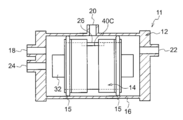
- FIG. 1 is a front sectional view of a separation system group and a separation system according to an embodiment of the present invention.
- the separation system group 10 has a configuration in which a plurality (three in the figure) of separation systems 11 are arranged in series.
- Each separation system 11 has a pressure vessel 12 and a separation module 14.
- the pressure vessel 12 includes a cylindrical storage portion 16 in which a cylindrical separation module 14 is fitted and stored via an O-ring 15. In a state where the separation module 14 is stored in the storage unit 16, the axial direction of the storage unit 16 and the axial direction of the separation module 14 are aligned.
- the storage unit 16 includes a raw material gas supply port 18, a sweep gas supply port 20, a raw material gas discharge port 22, and a sweep gas discharge port 24.
- the source gas supply port 18 is provided at one side end portion 16A of the storage unit 16 and faces one side end portion 26A of a laminate 26 of the separation module 14 described later, and supplies the source gas 28 to the storage unit 16. To do.
- the sweep gas supply port 20 is provided in the outer peripheral portion 16B of the storage unit 16 and is opposed to a later-described sweep gas introduction port 40C to supply the sweep gas 30 to the storage unit 16.
- the source gas discharge port 22 is provided at the other side end portion 16C of the storage unit 16, faces the other side end portion 26B of the stacked body 26, and passes through the stacked body 26 (the remaining gas 46). Are to be discharged.
- the sweep gas discharge port 24 is provided at one side end portion 16A of the storage unit 16, and discharges the carbon dioxide gas 44 as a gas component flowing out from the sweep gas 30 and a central tube 32 of the separation module 14 described later. .
- one of the source gas supply ports 18 of each pressure vessel 12 is connected to the source gas supply source 34 via a pipe, and the remaining source gas supply ports 18 are connected to the other pressure vessel 12. Is connected to the raw material gas discharge port 22 via a pipe.
- One of the sweep gas supply ports 20 of each pressure vessel 12 is connected to a sweep gas supply source 36 via a pipe, and the remaining sweep gas supply ports 20 are sweeps of other pressure vessels 12.
- the gas exhaust port 24 is connected via a pipe.
- the source gas discharge port 22 and the sweep gas discharge port 24 of the pressure vessel 12 farthest from the source gas supply port 18 connected to the source gas supply source 34 are not connected to other pressure vessels 12, and the gas Flows out to the outside.
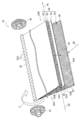
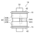
- FIG. 2 is a perspective view of the separation module 14 shown in FIG.
- the outermost periphery of the laminate 26 is covered with a covering member 40 in a state where one or more laminates 26 are wound around the central tube 32.
- Telescope prevention plates 42 are attached to both end portions of the member 40, respectively.
- the center tube 32 is a cylindrical tube body in which a plurality of circular through holes 32A are formed along the tube axis direction A on the outer peripheral surface thereof.
- One end side (one side end portion 26A side) of the center tube 32 is opened, and serves as a discharge port 32B through which the carbon dioxide gas 44 that permeates the laminated body 26 and collects from the through hole 32A is discharged.
- the other end portion side (the other side end portion 26 ⁇ / b> B side) of the center tube 32 is closed by a cap 48.
- the covering member 40 is formed of a blocking material that covers the laminated body 26 and can block the passage of gas to the outside.
- the covering member 40 has a two-layer structure of a Kapton tape 40A and a cover 40B.
- the Kapton tape 40A is wound around the outermost periphery of the laminate 26.
- a rectangular inlet 40 ⁇ / b> C serving as a place where the sweep gas 30 is introduced is provided at the center of the Kapton tape 40 ⁇ / b> A in the tube axis direction A.
- the longitudinal direction of the introduction port 40C is along the tube axis direction A, and a part of the laminated body 26 including the winding end portion 54A of the permeating gas channel member described later is exposed from the introduction port 40C.
- the cover 40B is a pair in the tube axis direction A, and is made of fiber reinforced plastic (Fiber Reinforced Plastics, FRP) or the like.
- FRP Fiber Reinforced Plastics
- the telescoping prevention plate 42 is a kind of anti-winding member, and a cylindrical portion 42A into which the central tube 32 is inserted, and a spoke portion 42B that extends radially from the outer peripheral surface of the cylindrical portion 42A and contacts the end surface of the laminate 26. And a cap portion 42C that is provided at the tip end portion of the spoke portion 42B and is fitted into the outer peripheral end portion of the cover 40B.
- FIG. 3 is a perspective view before winding the laminated body 26 of the separation module 14 shown in FIG.
- the laminate 26 is a carbon dioxide gas in which a supply gas flow path member 50 is folded inward with a facilitated transport film, which will be described later, in a state wound around the central tube 32 from the direction of arrow C in the figure.
- the carbon dioxide gas separation member 52 is sandwiched between the separation member 52 and adhered by an adhesive 56, and the carbon dioxide gas separation member 52 is adhered to the permeating gas flow path member 54 by an adhesive 58 on the inner side in the radial direction.
- the supply gas flow path member 50 is a member to which the raw material gas 28 including the carbon dioxide gas 44 is supplied from the one side end portion 26A side of the laminate 26, has a function as a spacer, and is a raw material gas. Since it is preferable to generate a turbulent flow in 28, a net-like member is preferably used. Since the gas flow path changes depending on the shape of the net, the shape of the unit cell of the net is selected from shapes such as rhombus and parallelogram according to the purpose.
- the material of the supply gas flow path member 50 is not limited in any way, but paper, fine paper, coated paper, cast coated paper, synthetic paper, cellulose, polyester, polyolefin, polyamide, polyimide, polysulfone, aramid, Examples thereof include resin materials such as polycarbonate and inorganic materials such as metal, glass and ceramics.
- the resin materials include polyethylene, polystyrene, polyethylene terephthalate, polytetrafluoroethylene (PTFE), polyethersulfone (PES), polyphenylene sulfide (PPS), polysulfone (PSF), polypropylene (PP), polyimide, polyetherimide, poly Suitable examples include ether ether ketone and polyvinylidene fluoride.
- Both ends in the width direction of the supply gas flow path member 50 are open because they serve as inlets for the source gas 28, but the winding end of the supply gas flow path member 50 is sealed with an adhesive 56. ing.
- the material of the adhesive 56 is not particularly limited.
- an epoxy resin for example, an epoxy resin, a vinyl chloride copolymer, a vinyl chloride-vinyl acetate copolymer, a vinyl chloride-vinylidene chloride copolymer, a vinyl chloride-acrylonitrile copolymer, Butadiene-acrylonitrile copolymer, polyamide resin, polyvinyl butyral, polyester, cellulose derivatives (nitrocellulose, etc.), styrene-butadiene copolymer, various synthetic rubber resins, phenol resin, urea resin, melamine resin, phenoxy resin, silicon Examples thereof include resins and urea formamide resins.
- the carbon dioxide gas separating member 52 has a two-layer structure, and supports a facilitated transport film 52A provided on the supply gas flow path member 50 side, and supports the facilitated transport film 52A on the permeate gas flow path member 54 side. And provided porous support 52B.
- the facilitated transport film 52 ⁇ / b> A has a function of selectively allowing the carbon dioxide gas 44 to permeate from the source gas 28.
- the facilitated transport film 52A preferably contains a carrier that reacts with the carbon dioxide gas 44 in the raw material gas 28 that passes through the supply gas flow path member 50 and a water-soluble polymer compound that supports the carrier.
- the facilitated transport film 52A generally has higher heat resistance than the dissolution diffusion film, and therefore the carbon dioxide gas 44 is selectively permeated even under a temperature condition of, for example, 80 ° C. to 200 ° C. Can be done.
- the water-soluble polymer compound absorbs the water vapor, and the facilitated transport film 52A containing the water-soluble polymer compound retains moisture, so that the carrier can be further absorbed. Since it becomes easy to transport, the separation efficiency is increased as compared with the case where a dissolution diffusion membrane is used.
- the facilitated transport film 52A preferably has a cross-linked structure from the viewpoint of improving heat resistance. From such a viewpoint, a preferred embodiment will be described.
- the facilitated transport film 52A is formed of, for example, a single or a plurality of crosslinkable groups selected from the following group (A), and has a crosslinked structure including a hydrolysis-resistant bond selected from the following group (B). It is composed of a conductive polymer compound layer.
- the facilitated transport membrane 52A is formed of a single crosslinkable group selected from the following group (A), and has resistance selected from the following group (B). It is preferably composed of a water-soluble polymer compound layer having a crosslinked structure containing a hydrolyzable bond.
- (A) group —OH, —NH 2 , —Cl, —CN, —COOH, epoxy group
- the water-soluble polymer compound is water-soluble.
- water-soluble means that the polymer compound is soluble in water at 80 ° C. or higher.
- the weight average molecular weight of the water-soluble polymer compound is appropriately selected within a range where a stable film can be formed. For example, when it has —OH as a crosslinkable group, the weight average molecular weight is 30,000 or more. Is preferred.
- the weight average molecular weight is more preferably 40,000 or more, and more preferably 50,000 or more.
- limiting in particular in the upper limit of a weight average molecular weight From a viewpoint of manufacturing aptitude, it is preferable that it is 6 million or less.
- the weight average molecular weight is 10,000 or more.
- the weight average molecular weight is more preferably 15,000 or more, and more preferably 20,000 or more.
- the weight average molecular weight of the water-soluble polymer compound is, for example, a value measured according to JIS K 6726 when PVA is used as the water-soluble polymer compound.
- the molecular weight nominally used by a catalog, a specification, etc. is used.
- crosslinkable group of the water-soluble polymer compound one capable of forming a hydrolysis-resistant crosslinked structure is selected, and a hydroxy group (—OH), an amino group (—NH 2 ), a carboxy group (—COOH), An epoxy group, a chlorine atom (—Cl), a cyano group (—CN) and the like can be mentioned.
- an amino group and a hydroxy group are preferable, and a hydroxy group is most preferable from the viewpoint of affinity with a carrier and a carrier carrying effect.
- water-soluble polymer compound having a single crosslinkable group examples include polyallylamine, polyacrylic acid, polyvinyl alcohol, polyvinylpyrrolidone, polyacrylamide, polyethyleneimine, polyvinylamine, polyornithine, polylysine and the like. Most preferred is polyvinyl alcohol.
- water-soluble polymer compound having a plurality of crosslinkable groups include polyvinyl alcohol-polyacrylate copolymer.
- Polyvinyl alcohol is also available as a commercial product, and examples thereof include Poval (manufactured by Kuraray), polyvinyl alcohol (manufactured by Aldrich), and J-Poval (manufactured by Nippon Vinegar Poval). Although there are various molecular weight grades, it is preferable to select one having a weight average molecular weight of 30,000 to 300,000.
- the crosslinked structure of the water-soluble polymer compound can be formed by a conventionally known method such as thermal crosslinking, ultraviolet crosslinking, electron beam crosslinking, radiation crosslinking, or photocrosslinking. Photocrosslinking or thermal crosslinking is preferred, and thermal crosslinking is most preferred.
- a composition containing a crosslinking agent together with the water-soluble polymer compound.
- the coating composition for forming a polymer compound layer used for forming the polymer compound layer may be simply referred to as “coating solution composition” or “composition”.
- cross-linking agent a cross-linking agent formed by selecting and containing a cross-linking agent having two or more functional groups capable of undergoing thermal cross-linking or photo-cross-linking by reacting with the water-soluble polymer having the single or plural cross-linkable groups is formed.
- the structure needs to be a hydrolysis-resistant crosslinked structure selected from the group (B).
- an epoxy crosslinking agent a polyvalent glycidyl ether, a polyhydric alcohol, a polyvalent isocyanate, a polyvalent aziridine, a haloepoxy compound, a polyvalent aldehyde, a polyvalent amine
- examples include organometallic crosslinking agents.
- Preferred are polyvalent aldehydes, organometallic crosslinking agents, and epoxy crosslinking agents, more preferred are organometallic crosslinking agents and epoxy crosslinking agents, and most preferred are glutaraldehyde and formaldehyde having two or more aldehyde groups. It is a polyvalent aldehyde.
- a preferable compound as an epoxy crosslinking agent is a compound having two or more epoxy groups, and a compound having four or more epoxy groups is also preferable.
- Epoxy crosslinking agents are also available as commercial products. For example, Kyoeisha Chemical Co., Ltd., Epolite 100MF (trimethylolpropane triglycidyl ether), Nagase ChemteX Corporation EX-411, EX-313, EX-614B, EX -810, EX-811, EX-821, EX-830, Epiol E400 manufactured by NOF Corporation, and the like.
- an oxetane compound having a cyclic ether is also preferably used as a compound similar to an epoxy crosslinking agent.
- the oxetane compound is preferably a polyvalent glycidyl ether having two or more functional groups.
- Examples of commercially available products include EX-411, EX-313, EX-614B, EX-810, EX-811, EX manufactured by Nagase ChemteX Corporation. -821, EX-830, and the like.
- polyvalent glycidyl ether examples include ethylene glycol diglycidyl ether, polyethylene glycol diglycidyl ether, glycerol polyglycidyl ether, diglycerol polyglycidyl ether, polyglycerol polyglycidyl ether, sorbitol polyglycidyl ether, pentaerythritol polyglycidyl ether, propylene Examples thereof include glycol glycidyl ether and polypropylene glycol diglycidyl ether.
- polyhydric alcohol examples include ethylene glycol, diethylene glycol, triethylene glycol, tetraethylene glycol, polyethylene glycol, glycerin, polyglycerin, propylene glycol, diethanolamine, triethanolamine, polyoxypropyl, oxyethyleneoxypropylene block copolymer , Pentaerythritol, sobiltol and the like.
- Examples of the polyvalent isocyanate include 2,4-toluylene diisocyanate and hexamethylene diisocyanate.
- Examples of the polyvalent aziridine include 2,2-bishydroxymethylbutanol-tris [3- (1-acylidinyl) propionate], 1,6-hexamethylenediethyleneurea, diphenylmethane-bis-4,4′- N, N′-diethylene urea and the like can be mentioned.
- Examples of the haloepoxy compound include epichlorohydrin and ⁇ -methylchlorohydrin.
- Examples of the polyvalent aldehyde include glutaraldehyde and glyoxal.
- Examples of the polyvalent amine include ethylenediamine, diethylenetriamine, triethylenetetramine, tetraethylenepentamine, pentaethylenehexamine, and polyethyleneimine.
- Examples of the organometallic crosslinking agent include organic titanium crosslinking agents and organic zirconia crosslinking agents.
- crosslinking agents for example, when a high molecular weight polyvinyl alcohol having a weight average molecular weight of 130,000 or more is used as the water soluble polymer compound, the reactivity with the water soluble polymer compound is good, and the hydrolysis resistance is high.
- an epoxy compound and glutaraldehyde are particularly preferable because an excellent crosslinked structure can be formed.
- polyallylamine having a weight average molecular weight of 10,000 or more it is possible to form a crosslinked structure having good reactivity with this water-soluble polymer compound and excellent hydrolysis resistance.
- Epoxy compounds, glutaraldehyde, and organometallic crosslinking agents are particularly preferred.
- an epoxy compound is particularly preferable as the crosslinking agent.
- the coating composition for forming a water-soluble polymer compound layer contains a crosslinking agent
- the content is 0.001 part by mass to 80 parts by mass with respect to 100 parts by mass of the crosslinkable group possessed by the water-soluble polymer compound. Parts, more preferably 0.01 parts by weight to 60 parts by weight, and most preferably 0.1 parts by weight to 50 parts by weight.
- the content is in the above range, the formability of the crosslinked structure is good and the shape maintaining property of the formed gel film is excellent.
- the crosslinked structure is a crosslink formed by reacting 0.001 mol to 80 mol of a crosslinking agent with 100 mol of the crosslinkable group possessed by the water-soluble polymer compound.
- a structure is preferred.
- alkali metal carbonate alkali metal bicarbonate, And selected from alkali metal hydroxides.
- alkali metal an alkali metal element selected from cesium, rubidium, potassium, lithium, and sodium is preferably used.
- Examples of the alkali metal carbonate include lithium carbonate, sodium carbonate, potassium carbonate, rubidium carbonate, and cesium carbonate.
- Examples of the alkali metal bicarbonate include lithium hydrogen carbonate, sodium hydrogen carbonate, potassium hydrogen carbonate, rubidium hydrogen carbonate, and cesium hydrogen carbonate.
- Examples of the alkali metal hydroxide include lithium hydroxide, sodium hydroxide, potassium hydroxide, rubidium hydroxide, and cesium hydroxide. Among these, a compound containing potassium, rubidium, or cesium as an alkali metal element is preferable from the viewpoint of good affinity with acidic gas. A compound containing potassium, rubidium, and cesium as alkali metal elements is also preferable.
- the facilitated transport membrane 52A since the hygroscopic facilitated transport membrane 52A is used as the carbon dioxide gas separation membrane, the facilitated transport membrane 52A becomes a gel due to moisture absorbed during manufacture, and the facilitated transport membrane 52A is formed between the membranes during manufacture. And a phenomenon (blocking) that sticks to other members. When this blocking occurs, when the facilitated transport film 52A is peeled off, the facilitated transport film 52A may cause a defect due to the sticking, resulting in a gas leak. Therefore, in this embodiment, it is preferable to prevent blocking.
- the carrier preferably contains two or more kinds of alkali metal carbonates. This is because, by using two or more kinds of carriers, blocking of the same kind of carriers in the film can be created by creating a non-uniformity of blocking by separating the distances. Furthermore, it is more preferable that the carrier includes a first alkali metal carbonate having deliquescence and a second alkali metal carbonate having a lower deliquescence and a lower specific gravity than the first alkali metal carbonate. Specifically, the first alkali metal carbonate includes cesium carbonate, and the second alkali metal carbonate includes potassium carbonate.
- the carrier includes the first alkali metal carbonate and the second alkali metal carbonate
- the second alkali metal carbonate having a small specific gravity is disposed on the film surface side of the facilitated transport film 52A, and the first alkali metal carbonate having a large specific gravity is disposed.
- the salt is disposed inside the facilitated transport film 52A.
- positioned at the film surface side is lower in deliquescence than the 1st alkali metal carbonate, compared with the case where the 1st alkali metal carbonate is arrange
- the first alkali metal carbonate having high deliquescence is disposed on the inner side of the membrane, blocking is suppressed as compared with the case where the second alkali metal carbonate is simply disposed on the entire membrane, and the carbon dioxide gas Separation efficiency can be increased. Since the second alkali metal carbonate only needs to be on the film surface side to prevent blocking, the second alkali metal carbonate is preferably contained in a smaller amount than the first alkali metal carbonate. Thereby, the amount of the first alkali metal carbonate having high deliquescence is relatively large in the entire membrane, and the carbon dioxide separation efficiency can be further increased.
- the total content of carriers in the water-soluble polymer compound layer is preferably 0.1 to 5 parts by weight, more preferably 0.2 to 4 parts by weight with respect to 1 part by weight of the water-soluble polymer compound. Part is more preferable, and 0.3 to 3 parts by mass is even more preferable.
- the content is in the above range, sufficient carrier ability is obtained, and salting out of the carrier, which is a concern when the carrier is excessively contained in the gel film, is suppressed.
- composition used for forming the facilitated transport film 52A various additives may be used in combination with the water-soluble polymer compound, the crosslinking agent, and the carbon dioxide carrier.
- the water as the solvent may also contain a small amount of water that is dried during production.
- a nitrogen-containing compound or a sulfur oxide that is a reaction promoting additive is used for the purpose of promoting the reaction between the acidic gas and the carrier. It is preferable.
- nitrogen-containing compounds include amino acids such as glycine, alanine, serine, proline, histidine, taurine, and diaminopropionic acid, hetero compounds such as pyridine, histidine, piperazine, imidazole, and triazine, monoethanolamine, diethanolamine, and triazine.
- Alkanolamines such as ethanolamine, monopropanolamine, dipropanolamine, tripropanolamine, cyclic polyetheramines such as cryptand [2.1] and cryptand [2.2], cryptand [2.2.1] Bicyclic polyetheramines such as cryptand [2.2.2], porphyrin, phthalocyanine, ethylenediaminetetraacetic acid and the like can be used.
- amino acids such as cystine and cysteine, polythiophene, dodecylthiol and the like can be used.
- the coating liquid composition used for forming the facilitated transport film 52A may contain an antioxidant as long as the effects of the present embodiment are not impaired.
- the addition of an antioxidant has the advantage of further improving wet heat resistance.
- suitable antioxidants include, for example, dibutylhydroxytoluene (BHT), Irganox 1010, Irganox 1035FF, Irganox 565, and the like.
- the composition used for forming the facilitated transport film 52A includes (1) a hydrophobic portion having an alkyl group having 3 to 20 carbon atoms or a fluorinated alkyl group having 3 to 20 carbon atoms and a hydrophilic portion.
- the specific compound and / or polymer particles are not simply present in the facilitated transport film 52A. It is made to be unevenly distributed near the film surface. At this time, it is unevenly distributed so that carbon dioxide can permeate. By doing in this way, generation
- the facilitated transport film 52A does not include or includes the polymer particles described later, and includes a compound having an alkyl group having 3 to 20 carbon atoms or a fluorinated alkyl group having 3 to 20 carbon atoms and a hydrophilic group, and a siloxane structure. 1 type or 2 types or more of compounds (specific compound) chosen from the group which consists of a compound which has.
- the content of the specific compound is preferably 0.0001 to 1% by mass, more preferably 0.0003 to 0.8% by mass, and more preferably 0.001 to 0% with respect to the total mass of the composition of the facilitated transport film 52A. More preferably, 1% by mass.
- the content of the specific compound is 0.0001% by mass or more, the effect of inhibiting the occurrence of blocking is excellent.
- the content of the specific compound is 1% by mass or less, the separability of acidic gas such as carbon dioxide is kept good.
- the compound having an alkyl group having 3 to 20 carbon atoms or a fluorinated alkyl group having 3 to 20 carbon atoms and a hydrophilic group tends to be unevenly distributed so as to cover the surface of the film when a coating film is formed by coating, It is effective in preventing the occurrence of blocking.
- the compound in the step of forming the facilitated transport film 52A containing the surfactant having an alkyl group or a fluorinated alkyl group, the compound is formed into a film due to the highly hydrophobic alkyl group or fluoroalkyl group. Blocking is effectively prevented by orienting the surface and reducing the surface energy of the film surface. Therefore, it is preferable that the compound has a higher hydrophobicity, that is, an alkyl group or fluoroalkyl group having a long carbon chain.
- a compound having a hydrophobic part and a hydrophilic part which contains an alkyl group having 3 to 20 carbon atoms or a fluorinated alkyl group having 3 to 20 carbon atoms, can be used.
- Specific examples include surfactants having an alkyl group having 3 to 20 carbon atoms or a fluorinated alkyl group having 3 to 20 carbon atoms in the hydrophobic portion.
- alkyl group having 3 to 20 carbon atoms examples include groups such as propyl, butyl, pentyl, hexyl, octyl, decyl, dodecyl, and eicosyl. Of these, a long-chain alkyl group is preferable because it is easily distributed on the film surface. Specifically, an alkyl group having 5 to 20 carbon atoms is more preferable, and more preferably 6 to 20 carbon atoms. It is an alkyl group. Among them, the case of having hexyl, octyl, decyl, dodecyl, and eicosyl is particularly preferable as the alkyl group.
- Examples of the fluorinated alkyl group having 3 to 20 carbon atoms include groups such as fluoropropyl, perfluorobutyl, perfluorohexyl, perfluorooctyl, and perfluorodecyl. Among them, it is preferable to have a fluoroalkyl group having a long carbon chain from the viewpoint of being easily distributed on the film surface, and specifically, a fluorinated alkyl group having 4 to 20 carbon atoms is preferable, more preferably carbon. A fluorinated alkyl group having 5 to 20 carbon atoms, more preferably a fluorinated alkyl group having 6 to 20 carbon atoms. Among them, it is preferable that the fluoroalkyl group has perfluorohexyl, perfluorooctyl, or perfluorodecyl.
- an alkyl group having no fluorine atom is preferred to a fluorinated alkyl group from the viewpoint of achieving a high level of compatibility between blocking inhibition and excellent acid gas separation.
- hydrophilic groups include hydroxyl groups, carboxylic acid groups, sulfonic acid groups, phosphoric acid groups, alkyleneoxy groups, amino groups, and quaternary amino groups.
- Examples of the surfactant having an alkyl group having 3 to 20 carbon atoms or a fluorinated alkyl group having 3 to 20 carbon atoms include the following compounds.
- Cationic surfactant- Quaternary ammonium salt type
- Chloride dodecyl dimethyl benzyl ammonium C 12 H 25 N + ( CH 3) 2 CH 2 C 6 H 5 Cl) ⁇ Octyltrimethylammonium chloride (C 8 H 17 N + (CH 3 ) 3 Cl) Decyltrimethylammonium chloride (C 10 H 21 N + (CH 3 ) 3 Cl) ⁇ Dodecyltrimethylammonium chloride (C 12 H 25 N + (CH 3 ) 3 Cl) ⁇ Tetradecyltrimethylammonium chloride (C 14 H 29 N + (CH 3 ) 3 Cl) Cetyltrimethylammonium chloride (CTAC) (C 16 H 33 N + (CH 3 ) 3 Cl) ⁇ Stearyltrimethylammonium chloride (C 18 H 37 N + (CH 3 ) 3 Cl) - hexadecyltrimethylammonium bromide (CTAB) (C 16 H 33 N +
- Nonionic surfactant (Ester type) Lauric glyceryl (C 11 H 23 COOCH 2 CH (OH) CH 2 OH, w: Glyceryl laurate) ⁇ Glyceryl monostearate (C 17 H 35 COOCH 2 CH (OH) CH 2 OH) ⁇ Sorbitan fatty acid ester (RCOOCH 2 CH (CHOH) 3 CH 2 O [R: alkyl having 3 to 20 carbon atoms]) ⁇ Sucrose fatty acid ester (RCOOC 12 H 21 O 10 [R: alkyl having 3 to 20 carbon atoms]) (Ether type) ⁇ Polyoxyethylene alkyl ether (RO (CH 2 CH 2 O) n H [R: alkyl having 3 to 20 carbon atoms]) ⁇ Pentaethylene glycol monododecyl ether (C 12 H 25 O (CH 2 CH 2 O) 5 H, w: Pentaethylene glycol monododecyl ether) -Oct
- Amphoteric surfactant (Alkyl betaine type) Lauryl betaine (C 12 H 25 N + ( CH 3) 2 CH 2 COO -) Stearyl betaine (C 18 H 37 N + ( CH 3) 2 CH 2 COO -) Dodecyl amino methyl dimethyl sulfopropyl betaine (C 12 H 25 N + ( CH 3) 2 (CH 2) 3 SO 3 -) - octadecyl amino methyl dimethyl sulfopropyl betaine (C 18 H 37 N + ( CH 3) 2 (CH 2) 3 SO 3 -) (Fatty acid amide propyl betaine type) - cocamidopropyl betaine (C 11 H 23 CONH (CH 2) 3 N + (CH 3) 2 CH 2 COO -, w: Cocamidopropyl betaine) ⁇ Cocamidopropyl hydroxysultain (C 11 H 23 CONH (CH 2 ) 3 N + (CH 3 ) 2 CH 2 CHOH
- the molecular weight of the surfactant having an alkyl group having 3 to 20 carbon atoms or a fluorinated alkyl group having 3 to 20 carbon atoms is preferably in the range of 60 to 2000, and more preferably in the range of 80 to 1500.
- the molecular weight is 60 or more, it is advantageous in that blocking can be suppressed uniformly as a film surface.
- the molecular weight is 2000 or less, it is possible to ensure acid gas separation while suppressing blocking.
- the content of the surfactant may be facilitated transport. It is preferably 0.01% by mass to 10% by mass and more preferably 0.01% by mass to 3% by mass with respect to the total solid content of the film 52A.
- the content of the “surfactant having an alkyl group having 3 to 20 carbon atoms or a fluorinated alkyl group having 3 to 20 carbon atoms” is 0.01% by mass or more, the effect of inhibiting the occurrence of blocking is excellent.
- the content of the surfactant is 10% by mass or less, the separability of the carbon dioxide gas 44 is kept good.
- a compound having a siloxane structure tends to be unevenly distributed so as to cover the surface of the film when the facilitated transport film 52A is formed by coating, and is effective in suppressing the occurrence of blocking.
- the siloxane structure is not particularly limited as long as it has a siloxane skeleton represented by “—Si—O—Si—” as a partial structure.
- a compound containing a structural unit having a siloxane structure in the side chain is preferable from the viewpoint of enhancing surface segregation when the facilitated transport film 52A is formed by coating.
- Siloxane compounds useful for introducing a siloxane structure into the molecule can be obtained from commercially available products such as X-22-173DX and X-22-173BX manufactured by Shin-Etsu Chemical Co., Ltd.
- One terminal reactive silicone is mentioned.
- Such a compound can be synthesized by reacting a siloxane having a reactive end with a compound having a cationic polymerizable group.
- a compound having a hydroxyl group at one end such as Chisso's Silaplane series FM-0411, FM-0421, FM-0425, etc., and epichlorohydrin, or in JP-A-11-80315. It can be synthesized by the method described.
- the content of the compound having a siloxane structure is 0.01% by mass to 10% by mass with respect to the total solid content of the facilitated transport film 52A.
- the content is preferably 0.01 to 3% by mass.
- the content of the compound having a siloxane structure is 0.01% by mass or more, the effect of inhibiting the occurrence of blocking is excellent.
- the content of the specific compound is 10% by mass or less, the separability of an acidic gas such as carbon dioxide is kept good.
- Polymer particles for example, particles of polyolefin (eg, polyethylene, polypropylene, polymethylpentene, etc.), polymethyl methacrylate, polystyrene, thermoplastic elastomer, silicone, etc. are preferably mentioned. Among these, polyolefin particles are preferable in that blocking can be uniformly suppressed.
- polyolefin eg, polyethylene, polypropylene, polymethylpentene, etc.
- polymethyl methacrylate e.g., polystyrene, thermoplastic elastomer, silicone, etc.
- polyolefin particles are preferable in that blocking can be uniformly suppressed.
- the average particle diameter of the polymer particles is preferably in the range of 0.01 ⁇ m to 1000 ⁇ m.
- the particle diameter of the polymer particles is 0.01 ⁇ m or more, the particles do not clog too tightly, so that the area occupied on the film surface when the coating film is formed can be ensured without lowering the separation performance.
- the average particle diameter of the polymer particles is 1000 ⁇ m or less, there is not much polymer on the film surface when the coating film is formed, the carbon dioxide permeability does not decrease, and the polymer particles are difficult to fall off.
- the average particle diameter of the polymer particles is more preferably in the range of 0.02 ⁇ m to 750 ⁇ m, still more preferably in the range of 0.03 ⁇ m to 500 ⁇ m, and particularly preferably in the range of 0.1 ⁇ m to 50 ⁇ m.
- the particle diameter of the polymer particles is a value measured using FPAR1000 manufactured by Otsuka Electronics Co., Ltd.
- the specific gravity of the polymer particles is preferably in the range of 0.5 g / cm 3 to 1.3 g / cm 3 .
- the specific gravity of the polymer particles is 0.5 g / cm 3 or more, it is difficult to block the membrane surface, and the carbon dioxide permeability is not easily impaired.
- the specific gravity of the polymer particles is 1.3 g / cm 3 or less, it is difficult to settle in the coating liquid, and the polymer is likely to be present on the film surface when the coating film is formed, so that the blocking inhibiting effect is good. become.
- the specific gravity of the polymer particles more preferably in the range of 0.52g / cm 3 ⁇ 1.28g / cm 3, more preferably in the range of from 0.55g / cm 3 ⁇ 1.27g / cm 3.
- the polymer particles can be used, for example, in the form of an emulsion (emulsion) in which a polymer is dispersed in a liquid state in an aqueous medium and a dispersion (suspension) in which a polymer is dispersed in a solid state in an aqueous medium. .
- polystyrene resin particles As the polymer particles, commercially available products may be used. For example, Chemipearl w-308, w-400, w-100, wp-100, and A-100 manufactured by Mitsui Chemicals, Inc. may be used. Can be used.
- the total content in the facilitated transport film 52A is preferably such that the area occupied by the polymer particles on the surface of the facilitated transport film 52A is 0.1% to 60%.
- the occupied area by the polymer particles is 0.1% or more, the effect of inhibiting the occurrence of blocking is excellent. Further, when the area occupied by the polymer particles is 60% or less, the acid gas separability can be kept good while blocking is suppressed.
- the occupied area of the polymer particles is more preferably 0.5% to 30%, further preferably 1% to 10%.
- the occupied area is determined by image analysis of the particle coverage per unit area using a scanning electron microscope (JSM6610, manufactured by JEOL).
- the specific gravity of the polymer particles is low. Therefore, in the process of forming the facilitated transport film 52A using a coating liquid containing polymer particles and drying, the polymer is applied to the coating film surface. Particles are unevenly distributed. Thereby, the polymer particles are unevenly distributed on the surface to prevent blocking without performing a special treatment such as applying only to the surface.
- the facilitated transport film 52A is prepared on the porous support 52B by preparing a first coating liquid containing polymer particles and the specific compound, and a second coating liquid not containing the polymer particles and the specific compound, respectively.
- the second coating liquid and the first coating liquid so as to be in the multilayer order, it is possible to form a layer in which polymer particles and a specific compound are unevenly distributed on the film surface. Since these compounds and polymer particles are not compatible with other components constituting the water-soluble polymer compound layer, they do not impair the separation ability inherent in the water-soluble polymer compound layer.
- porous support As the porous support 52B that constitutes the carbon dioxide gas separation member 52 together with the facilitated transport film 52A, the same material as the supply gas flow path member 50 can be used.
- the permeating gas flow path member 54 that constitutes the laminate 16 together with the carbon dioxide gas separating member 52 is a member that guides the carbon dioxide gas 44 that has reacted with the carrier and permeated the carbon dioxide gas separating member 52 toward the through hole 32A. It is.
- the permeate gas channel member 54 has a function as a spacer, and has a function of flowing the permeated carbon dioxide gas 44 to the inside of the permeate gas channel member 54, and further penetrates an adhesive 56 described later.
- the permeate gas flow path member 54 is preferably a net-like member.
- the material of the permeating gas flow path member 54 can be the same as that of the supply gas flow path member 50.
- Both ends in the width direction of the permeate gas channel member 54 are sealed with an adhesive 58, while the winding end 54A of the permeate gas channel member 54 is opened so that the sweep gas 30 is introduced. ing.
- the material of the adhesive 58 can be the same as that of the adhesive 56.
- the (winding start end) is fixed to the outer peripheral surface of the center tube 32.
- a long supply gas flow path member 50 is sandwiched between long carbon dioxide gas separation members 52 in which a facilitated transport film 52A is folded inward.
- the carbon dioxide gas separating member 52 may be divided into two parts, but may be shifted and folded as shown in FIG. 4B.
- the end of winding of the supply gas flow path member 50 is sealed with an adhesive 56, and the supply gas flow path member 50 and the carbon dioxide gas separation member are sealed. 52 is adhered.
- the longer carbon dioxide gas separation member 52 in the folded state extends beyond the winding end of the supply gas flow path member 50.
- the adhesive 62 is also applied to the inner surface of the stretched end (the end of winding of the carbon dioxide gas separating member 52). Note that the adhesive 62 is not necessary when the carbon dioxide gas separating member 52 is divided into two parts.
- an adhesive 58 is applied to both ends in the width direction on the outer surface of the shorter carbon dioxide gas separating member 52 in the folded carbon dioxide gas separating member 52.
- the supply gas flow path member 50 is sandwiched between the longitudinally central surface of the permeate gas flow path member 54 fixed to the central tube 32 via adhesives 58 and 62.
- a carbon dioxide gas separation member 52 is attached.
- the adhesive 58 penetrates to the inside of the permeate gas flow path member 54 and seals both ends in the width direction of the permeate gas flow path member 54 together with permeation of the adhesive 58 shown in FIG. 4E described later.
- the adhesive 62 does not permeate the permeate gas flow path member 54, and the carbon dioxide gas separation member 52 and the permeate gas flow to prevent the sweep gas 30 from entering the supply gas flow path member 50 side.
- the road member 54 is still adhered.
- the laminate 26 including the supply gas flow path member 50, the carbon dioxide gas separation member 52, and the permeate gas flow path member 54 is formed.
- an adhesive is applied to both ends in the width direction with respect to the surface of the carbon dioxide gas separating member 52 attached to the permeating gas channel member 54 (the surface opposite to the attached surface). 58 is applied.
- the laminated body 26 is wound around the central tube 32 in the direction of arrow C in the figure so as to cover the through hole 32A with the permeating gas channel member 54.
- tension is applied to the permeating gas channel member 54 extending from the laminate 26.
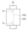
- the hot melt 70 is applied to the permeating gas flow path member 54 around the laminate 26.
- a permeate gas flow path member 54 extending from the laminate 26 is further wound around the laminate 26 and fixed via the hot melt 70, and the permeate extending before the hot melt 70.
- the gas flow path member 54 is cut.
- the amount and area are adjusted so that the entire winding end portion 54C of the permeating gas channel member 54 is not sealed.
- the Kapton tape 40A as the covering member 40 is wound around the outermost periphery of the laminate 26 wound around the central tube 32.
- both ends in the width direction may be cut.
- the adhesive 58 that permeates the both end portions in the width direction of the permeating gas channel member 54 is also applied to the inside of the both end portions in the width direction in consideration of cutting.
- the inlet 40C of the sweep gas 30 is formed in the Kapton tape 40A. At this time, the inlet 40C is formed so that the winding end portion 54A of the permeating gas channel member 54 is exposed.
- the telescope prevention plate 42 is attached to the both ends of the laminated body 26 and the Kapton tape 40A.
- the separation module 14 according to the embodiment of the present invention is obtained.
- the O-ring 15 is fitted into the outer peripheral surface of the telescope prevention plate 42 in the separation module 14.
- the separation module 14 is fitted into the inner peripheral surface of the storage portion 16 of the pressure vessel 12 via the O-ring 15 and stored in the storage portion 16.
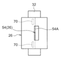
- FIG. 7 is a schematic view showing a state in which the laminated body 26 is spread frontward in the separation module according to the reference example of the embodiment of the present invention.
- the laminate 26 is wound around the outer peripheral surface of the center tube 32.
- the permeate gas flow path member 102 in the stacked body 26 is sealed not only by the width direction both end portions 102A but also the winding end end portion 102B by the adhesive 104. Yes.
- a partition member 106 is provided in the center of the center tube 32 to block the center.
- the raw material gas 28 (or the remaining gas 46) containing the carbon dioxide gas 44 is supplied to the laminate 26 from one end side.
- the structure of the facilitated transport film 52A separates the raw material gas 28 into the carbon dioxide gas 44 and the remaining gas 46, and the carbon dioxide gas 44 passes through the permeating gas channel member 102 and the through hole 32A.
- the remaining gas 46 is separately discharged from the laminated body 26 on the other end side through the central tube 32.
- the sweep gas 30 is supplied from one end side of the central tube 32, hits the partition member 106, flows into the permeate gas flow path member 102 through the through hole 32 ⁇ / b> A.
- a sweep gas is provided at a location such as the vicinity of a portion where the sealing portion by the adhesive 104 at the both ends 102A in the width direction intersects with a sealing portion by the adhesive 104 at the winding end portion 102B. Since 30 does not spread, the stagnation of carbon dioxide gas 44 occurs at the same location, and the separation efficiency of carbon dioxide gas 44 cannot be sufficiently increased.
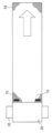
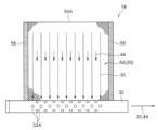
- FIG. 5 is a schematic diagram showing a state in which the laminate 26 is spread frontward in the separation module 14 according to the embodiment of the present invention.
- the source gas 28 is supplied from the source gas supply port 18 into the storage unit 16 of the pressure vessel 12.
- the source gas 28 supplied into the storage unit 16 is supplied to one side end portion 26 ⁇ / b> A of the stacked body 26 of the separation module 14.
- the sweep gas 30 is supplied from the sweep gas supply port 20 into the storage portion 16 of the pressure vessel 12 in a direction substantially perpendicular to the supply direction of the source gas 28.
- the sweep gas 30 supplied into the storage unit 16 is supplied to the introduction port 40 ⁇ / b> C formed in the covering member 40 of the separation module 14.
- the laminate 26 of the separation module 14 is covered with a covering member 40 as shown in FIG. 2, and the sweep gas 30 is also introduced into the inlet 40C of the covering member 40 from the outside.
- the raw material gas 28 supplied from one side end portion 26A of the laminate 26 to the supply gas flow path member 50 by the gas pressure of the sweep gas 30 is, as shown in FIG. Without flowing out, the gas passes through the supply gas flow path member 50 and is discharged to the storage unit 16, and is discharged from the source gas discharge port 22 to the outside of the pressure vessel 12.
- the carbon dioxide gas 44 in the raw material gas 28 passing through the supply gas flow path member 50 is separated by passing through the facilitated transport film 52A of the carbon dioxide gas separation member 52, and the permeated gas flow path member 54 and the through hole are separated.
- the gas is accumulated in the central tube 32 through 32 ⁇ / b> A, and discharged from the sweep gas discharge port 24 to the outside of the pressure vessel 12 through the discharge port 32 ⁇ / b> B of the central tube 32.
- the winding end end portion 54A of the permeate gas channel member 54 opened from the inlet 40C of the covering member 40 (Kapton tape 40A) is used. Since the sweep gas 30 is introduced into the permeate gas channel member 54 and travels toward the central tube 32, the sweep gas 30 sweeps the carbon dioxide gas 44 while the sweep gas 30 sweeps the carbon dioxide gas 44, as shown in FIG. Go inside. Thereby, the retention of the carbon dioxide gas 44 inside the permeating gas channel member 54 can be suppressed, and the separation efficiency of the carbon dioxide gas 44 can be increased.
- both end portions in the width direction of the permeating gas flow path member 54 are sealed.
- the gas 30 and the carbon dioxide gas 44 do not flow out, and flow through the inside of the permeating gas channel member 54 evenly.
- the winding end end portion 54A of the permeating gas channel member 54 is exposed from the introduction port 40C.
- the gas 30 is easily introduced into the winding end portion 54A without passing through the inside of the covering member 40.
- the source gas supply port 18 is provided at one side end 16A of the storage unit 16, and the sweep gas supply port 20 is stored. Since the supply direction of the raw material gas 28 and the sweep gas 30 is substantially perpendicular, the sweep gas 30 sweeps the carbon dioxide gas 44 flowing into the permeate gas flow path member 54 because it is provided on the outer peripheral portion 16B of the portion 16. It becomes easy to do.
- one sweep gas supply port 20 is a sweep gas supply source 36.
- the remaining sweep gas supply port 20 is connected to the sweep gas discharge port 24 of the other pressure vessel 12.
- the sweep gas supply source 36 can be reduced compared with the case where the individual sweep gas supply source 36 is connected to the sweep gas supply port 20 of each pressure vessel 12.
- separation member examples include a dissolution diffusion membrane, a Knudsen diffusion membrane, a molecular sieve membrane, and a surface diffusion membrane.
- gas component of the source gas 28 separated by the separation member is not limited to the carbon dioxide 44, and may be other gas such as hydrogen.
- the case where the supply direction of the raw material gas 28 and the discharge direction of the sweep gas 30 and the carbon dioxide gas 44 from the center pipe 32 are opposite has been described, but the supply direction and the discharge direction are the same. Also good. Further, when the sweep gas 30 is introduced from the introduction port 40C as in the present embodiment, the total pressure on the front and back of the carbon dioxide gas separation member 52 can be made substantially close, so that leakage from the laminate 16 is suppressed and supplied. The flow direction of the gas flow path member 50 and the permeate gas flow path member 54 can be changed.
- the sweep gas 30 flows from the introduction port 40C through the inside of the covering member 40 (Kapton tape 40A) to the introduction port 40C.
- the winding end portion of the supply gas flow path member 50 is sealed with the adhesive 56
- it may be opened.
- the method of sealing is not limited to the method of penetrating the adhesive, and may be a method of attaching a double-sided tape or the like.
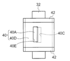
- the cover 40B covering the Kapton tape 40A covers both ends of the outer peripheral surface of the Kapton tape 40A in the tube axis direction A with the center portion of the Kapton tape 40A in the tube axis direction A sandwiched so that the introduction port 40C is exposed.
- the configuration of the cover 40B is not limited to the above.
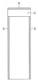
- a cover 40D as shown in FIG. 6 may be used instead of the cover 40B.
- the cover 40D covers the entire area of the Kapton tape 40A, and the introduction port 40E is formed so that a part of the Kapton tape 40A including the introduction port 40C is exposed.
- the covering member 40 may be a single layer or three or more layers.
- the carbon dioxide gas separation member composed of the facilitated transport film and the porous support was produced by applying and drying this coating composition using PTFE / PP nonwoven fabric (manufactured by GE) as the porous support.
- the produced carbon dioxide gas separation member was folded in half with the facilitated transport membrane inside.
- Kapton tape was applied to the valley part folded in half, and the end part of the supply gas flow path member was reinforced so as not to damage the surface shape of the film valley part.
- network of thickness 0.5mm was inserted
- the end of winding of the polypropylene net is sealed with an adhesive.
- Adhesive (Three Bond Co., Ltd.) TB2088E) is applied to both ends of the carbon dioxide gas separation member in the width direction, and a tricot knitted epoxy-impregnated polyester permeating gas flow path member is stacked, and these laminates are placed around the central tube. Wrapped in multiple. Note that both end portions in the width direction of the permeate gas channel member are sealed with an adhesive. Further, a Kapton tape was wound around the laminate, and a sweep gas inlet was provided so that a part of the laminate was exposed to the Kapton tape. Next, the telescope prevention board was attached to the both-ends part of a laminated body and a Kapton tape.
- both ends of the outer peripheral surface of the Kapton tape in the tube axis direction were covered with a cover, with the center portion of the Kapton tape in the tube axis direction sandwiched so that at least a part of the introduction port was exposed.
- the separation module 1 (see FIG. 2) was produced.
- the membrane area of the separation module 1 was 0.05 m 2 .
- the produced separation module 1 was housed in a pressure vessel having a sweep gas supply port in a direction perpendicular to the raw material gas supply port to obtain a separation system 1.
- a separation module 2 was produced in the same manner as the separation module 1 except that the winding end of the polypropylene net was not sealed with an adhesive.
- the produced separation module 2 was housed in a pressure vessel having a sweep gas supply port in a direction perpendicular to the raw material gas supply port to obtain a separation system 2.
- Separation module is provided by providing a partition member in the central tube and sealing not only both ends in the width direction of the permeate gas channel member with an adhesive, but also sealing the winding end of the permeate gas channel member with an adhesive. 3 (see FIG. 7) was produced.
- the produced separation module 3 was housed in a pressure vessel having a sweep gas supply port parallel to the source gas supply port to obtain a separation system 3.
- Table 1 shows the results of gas separation evaluation using each of the produced separation systems 1 to 3 by flowing a raw material gas and a sweep gas and dividing the results into an example and a comparative example.
- the gas separation evaluation was performed by analyzing the permeated carbon dioxide gas with a gas chromatograph and calculating the CO 2 permeation rate (P (CO 2 )) and the CO 2 / H 2 separation factor ( ⁇ ).
- gas conditions are the same for all examples and are as follows.
- the sweep gas supplied from the sweep gas supply port has the conditions shown in Table 1.
- the separation systems according to Examples 1 to 4 have improved CO 2 permeation rate (P (CO 2 )) and CO 2 / H 2 separation factor ( ⁇ ) compared to the separation system according to Example 5. I understand that.
Landscapes
- Chemical & Material Sciences (AREA)
- Chemical Kinetics & Catalysis (AREA)
- Engineering & Computer Science (AREA)
- Analytical Chemistry (AREA)
- General Chemical & Material Sciences (AREA)
- Oil, Petroleum & Natural Gas (AREA)
- Separation Using Semi-Permeable Membranes (AREA)
Description
本発明は、分離モジュール、分離システム及び分離システム群に関する。
近年、ガス中の二酸化炭素ガス等のガス成分を選択的に分離する分離モジュールの開発が進んでいる。
例えば、特開平5-131123号公報には、供給されるガス中のガス成分を透過して分離させる分離部材と、分離部材を透過したガス成分の流路となる透過ガス流路用部材とを含む積層体を、外周面に貫通孔が形成された管体に巻き付けて、巻き付けた積層体を被覆部材で覆う分離モジュールが開示されている。
この分離モジュールでは、透過ガス流路用部材の幅方向両端部と巻き終わり端部を接着剤で封止して、分離部材を透過したガス成分が透過ガス流路用部材内を流れて貫通孔に向かうようになっている。そして、この透過ガス流路用部材内でのガス成分の滞留を防ぐために、管体から貫通孔を介して透過ガス流路用部材内にスイープガスを流している。
この分離モジュールでは、透過ガス流路用部材の幅方向両端部と巻き終わり端部を接着剤で封止して、分離部材を透過したガス成分が透過ガス流路用部材内を流れて貫通孔に向かうようになっている。そして、この透過ガス流路用部材内でのガス成分の滞留を防ぐために、管体から貫通孔を介して透過ガス流路用部材内にスイープガスを流している。
しかしながら、特開平5-131123号公報の構成では、透過ガス流路用部材内の、例えば幅方向両端部の封止部分と巻き終わり端部の封止部分との交差する近傍等の箇所にスイープガスが行き渡らないため、同箇所でガス成分の滞留が起こり、ガス成分の分離効率を十分に高めることができない。
本発明は上記事情に鑑みてなされたものであり、ガス成分の分離効率が高い分離モジュール、分離システム及び分離システム群を提供することを目的とする。
本発明の上記課題は下記の手段によって解決された。
本発明の第1態様に係る分離モジュールは、外周面に貫通孔が形成された管体と、ガスが供給される供給ガス流路用部材と、前記供給ガス流路用部材を通過する前記ガス中のガス成分を透過して分離させる分離部材と、前記分離部材を透過した前記ガス成分が前記貫通孔に向かって流れる透過ガス流路用部材と、を積層し、前記貫通孔を覆うように前記管体に多重に巻き付けられた積層体と、前記積層体を覆って外部への前記ガスの通過を遮断すると共に、外部から前記透過ガス流路用部材の開放された巻き終わり端部へのスイープガスの導入口が形成された被覆部材と、を有する。
本発明の第1態様に係る分離モジュールは、外周面に貫通孔が形成された管体と、ガスが供給される供給ガス流路用部材と、前記供給ガス流路用部材を通過する前記ガス中のガス成分を透過して分離させる分離部材と、前記分離部材を透過した前記ガス成分が前記貫通孔に向かって流れる透過ガス流路用部材と、を積層し、前記貫通孔を覆うように前記管体に多重に巻き付けられた積層体と、前記積層体を覆って外部への前記ガスの通過を遮断すると共に、外部から前記透過ガス流路用部材の開放された巻き終わり端部へのスイープガスの導入口が形成された被覆部材と、を有する。
この構成によれば、積層体が被覆部材によって覆われており、また被覆部材の導入口も外部からスイープガスが導入されるため、そのスイープガスのガス圧により、供給ガス流路用部材に供給されたガスは、原則途中で外側に流れ出すことなく、供給ガス流路用部材を通過して外部へ排出される。この供給ガス流路用部材を通過するガス中のガス成分は、分離部材を透過して分離され、透過ガス流路用部材及び貫通孔を介して管体に集積され、管体から排出される。
そして、透過ガス流路用部材をガス成分が流れる際、外部から被覆部材の導入口及び透過ガス流路用部材の開放された巻き終わり端部を介して透過ガス流路用部材の内部へスイープガスが導入され中心管に向かうため、スイープガスがガス成分をスイープしながら透過ガス流路用部材の内部に行き渡る。これにより、透過ガス流路用部材の内部でのガス成分の滞留を抑制して、ガス成分の分離効率を高くすることができる。
そして、透過ガス流路用部材をガス成分が流れる際、外部から被覆部材の導入口及び透過ガス流路用部材の開放された巻き終わり端部を介して透過ガス流路用部材の内部へスイープガスが導入され中心管に向かうため、スイープガスがガス成分をスイープしながら透過ガス流路用部材の内部に行き渡る。これにより、透過ガス流路用部材の内部でのガス成分の滞留を抑制して、ガス成分の分離効率を高くすることができる。
本発明の第2態様に係る分離モジュールでは、第1態様において、前記透過ガス流路用部材の幅方向両端部は封止され、前記供給ガス流路用部材の幅方向両端部は前記ガスの導入口となり、前記供給ガス流路用部材の巻き終わり端部は封止されている。
この構成によれば、スイープガスが被覆部材の導入口を介して開放された透過ガス流路用部材の巻き終わり端部から導入されても、供給ガス流路用部材の巻き終わり端部は封止されているため供給ガス流路用部材の内部にはスイープガスが導入されない。したがって、スイープガスによって、供給ガス流路用部材に供給されるガスが乱されてしまうことを回避できる。また、透過ガス流路用部材の幅方向両端部は封止されているため、この幅方向両端部からスイープガスやガス成分が流出することがなく、透過ガス流路用部材の内部をまんべんなく流れる。
本発明の第3態様に係る分離モジュールでは、第1態様又は第2態様において、前記スイープガスの導入口からは、前記透過ガス流路用部材の巻き終わり端部が露出している。
この構成によれば、スイープガスが被覆部材の内部を通ることなく巻き終わり端部へ導入され易い。
本発明の第4態様に係る分離モジュールでは、第1態様~第3態様の何れか1つの態様において、前記分離部材は、前記供給ガス流路用部材を通過する前記ガス中のガス成分である酸性ガスと反応するキャリア及び前記キャリアを担持する水溶性高分子化合物を含有し、前記供給ガス流路用部材側に設けられた促進輸送膜と、前記透過ガス流路用部材側に設けられ、前記促進輸送膜を支持する多孔質支持体と、を有する。
この構成によれば、気体に水蒸気が含まれていても、当該水蒸気を水溶性高分子化合物が吸湿して当該水溶性高分子化合物を含有する促進輸送膜が水分を保持することでキャリアが酸性ガスを輸送し易くなるので、溶解拡散膜等の他の分離膜を用いる場合に比べて分離効率が高まる。
本発明の第5態様に係る分離モジュールでは、第4態様において、前記促進輸送膜は、前記キャリアと前記水溶性高分子化合物の他、炭素数3~20のアルキル基又は炭素数3~20のフッ化アルキル基と親水性基とを有する化合物及びシロキサン構造を有する化合物からなる群より選ばれる化合物、並びに平均粒子径が0.01μm~1000μmでかつ比重が0.5g/cm3~1.3g/cm3のポリマー粒子から選ばれる少なくとも一種を含む。
この構成によれば、分離モジュールの製造過程においてブロッキングの発生を抑制することができる。
本発明の第6態様に係る分離モジュールでは、第4態様又は第5態様において、前記キャリアは、アルカリ金属塩である。
この構成によれば、供給ガス流路用部材を通過するガス中の二酸化炭素ガスが、アルカリ金属塩と反応する。
本発明の第7態様に係る分離システムでは、第1態様~第6態様の何れか1つに記載の分離モジュールと、前記分離モジュールを収納する筒状の収納部と、前記収納部の側端部に設けられ前記積層体の一方の側端部と対向する前記ガスの供給口と、前記収納部の外周部に設けられ前記導入口と対向する前記スイープガスの供給口と、前記収納部の側端部に設けられ前記管体から流れ出す前記ガス成分及び前記スイープガスの排出口と、前記収納部の側端部に設けられ前記積層体の他方の側端部と対向する前記ガスの排出口と、を含む容器と、を有する。
この構成によれば、ガスとスイープガスの供給方向が略直角となるので、スイープガスが透過ガス流路用部材内に流れるガス成分をスイープし易くなる
本発明の第8態様に係る分離システム群は、第7態様に記載の分離システムを直列に配置し、各容器のスイープガスの供給口のうち、一の供給口はスイープガス供給源に繋がれ、残りの供給口は他の容器のスイープガスを排出する排出口に繋がれている。
この構成によれば、各容器のスイープガスの供給口にスイープガス供給源を繋げる場合に比べて、スイープガス供給源を削減することができる。
本発明によれば、分離モジュールの分離効率が高くされる。
以下、添付の図面を参照しながら、本発明の実施形態に係る分離モジュール、分離システム及び分離システム群について具体的に説明する。なお、図中、同一又は対応する機能を有する部材(構成要素)には同じ符号を付して適宜説明を省略する。
<分離システム群及び分離システム>
まず、本発明の実施形態に係る分離システム群及び分離システムについて説明する。図1は、本発明の実施形態に係る分離システム群及び分離システムの正面断面図である。
まず、本発明の実施形態に係る分離システム群及び分離システムについて説明する。図1は、本発明の実施形態に係る分離システム群及び分離システムの正面断面図である。
図1に示すように、本発明の実施形態に係る分離システム群10は、複数(図では3つ)の分離システム11を直列に配置した構成である。
各分離システム11は、圧力容器12と、分離モジュール14とを有している。
圧力容器12は、Oリング15を介して筒状の分離モジュール14を内周面に嵌め込んで収納した筒状の収納部16を含んでいる。収納部16に分離モジュール14が収納された状態では、収納部16の軸方向と分離モジュール14の軸方向が揃っている。
収納部16は、原料ガス供給口18と、スイープガス供給口20と、原料ガス排出口22と、スイープガス排出口24と、を有している。
原料ガス供給口18は、収納部16の一方の側端部16Aに設けられ、後述する分離モジュール14の積層体26の一方の側端部26Aと対向し、原料ガス28を収納部16に供給するものである。
スイープガス供給口20は、収納部16の外周部16Bに設けられ、後述するスイープガスの導入口40Cと対向し、スイープガス30を収納部16に供給するものである。
原料ガス排出口22は、収納部16の他方の側端部16Cに設けられ、積層体26の他方の側端部26Bと対向し、積層体26を通過した原料ガス28(残余のガス46)を排出するものである。
スイープガス排出口24は、収納部16の一方の側端部16Aに設けられ、スイープガス30及び後述する分離モジュール14の中心管32から流れ出すガス成分としての二酸化炭素ガス44を排出するものである。
ここで、各圧力容器12の原料ガス供給口18のうち一の原料ガス供給口18は、原料ガス供給源34に配管を介して繋がれ、残りの原料ガス供給口18は他の圧力容器12の原料ガス排出口22に配管を介して繋がれている。また、各圧力容器12のスイープガス供給口20のうち一のスイープガス供給口20はスイープガス供給源36に配管を介して繋がれ、残りのスイープガス供給口20は他の圧力容器12のスイープガス排出口24に配管を介して繋がれている。
ただし、原料ガス供給源34に繋がれた原料ガス供給口18から最も遠い圧力容器12の原料ガス排出口22とスイープガス排出口24は、他の圧力容器12には繋がれておらず、ガスが外部に流れ出るようになっている。
ただし、原料ガス供給源34に繋がれた原料ガス供給口18から最も遠い圧力容器12の原料ガス排出口22とスイープガス排出口24は、他の圧力容器12には繋がれておらず、ガスが外部に流れ出るようになっている。
<分離モジュール>
次に、本発明の実施形態に係る分離モジュール14について説明する。図2は、図1に示す分離モジュール14の斜視図である。
次に、本発明の実施形態に係る分離モジュール14について説明する。図2は、図1に示す分離モジュール14の斜視図である。
分離モジュール14は、その基本構造として、中心管32の周りに、積層体26が単数あるいは複数が巻き付けられた状態で積層体26の最外周が被覆部材40で覆われ、これら積層体26及び被覆部材40の両側端部にそれぞれテレスコープ防止板42が取り付けられて構成される。
このような構成の分離モジュール14では、積層体26の一方の側端部26A側から積層体26に二酸化炭素ガスを含む原料ガス28が供給されると、後述する積層体26の構成により、原料ガス28をガス成分である二酸化炭素ガス44と残余のガス46に分離して二酸化炭素ガス44は中心管32から、残余のガス46は積層体26の他方の側端部26B側から別々に排出する。
このような構成の分離モジュール14では、積層体26の一方の側端部26A側から積層体26に二酸化炭素ガスを含む原料ガス28が供給されると、後述する積層体26の構成により、原料ガス28をガス成分である二酸化炭素ガス44と残余のガス46に分離して二酸化炭素ガス44は中心管32から、残余のガス46は積層体26の他方の側端部26B側から別々に排出する。
中心管32は、その外周面に円形の貫通孔32Aが管軸方向Aに沿って複数形成された円筒状の管体である。中心管32の管一端部側(一方の側端部26A側)は開口し、積層体26を透過して貫通孔32Aから集合した二酸化炭素ガス44が排出される排出口32Bとなっている。また、中心管32の管他端部側(他方の側端部26B側)は、キャップ48によって閉じられている。
被覆部材40は、積層体26を覆って外部へのガスの通過を遮断しうる遮断材料で形成されている。
この被覆部材40は、カプトンテープ40Aと、カバー40Bとの二層構造となっている。
この被覆部材40は、カプトンテープ40Aと、カバー40Bとの二層構造となっている。
カプトンテープ40Aは、積層体26の最外周に巻きつけられている。このカプトンテープ40Aの管軸方向Aの中央部には、スイープガス30の導入箇所となる長方形の導入口40Cが設けられている。この導入口40Cの長手方向は管軸方向Aに沿っており、導入口40Cから後述する透過ガス流路用部材の巻き終わり端部54Aを含む積層体26の一部が露出している。
カバー40Bは、管軸方向Aに一対となっており、繊維強化プラスチック(Fiber Reinforced Plastics、FRP)等で構成されている。このカバー40Bは、導入口40Cが露出するようにカプトンテープ40Aにおける管軸方向Aの中央部を挟んで、カプトンテープ40Aにおける管軸方向Aの外周面両端部を覆っている。
テレスコープ防止板42は、巻きズレ防止部材の一種であり、中心管32が挿入される筒部42Aと、この筒部42Aの外周面から放射状に延び積層体26の端面に当接するスポーク部42Bと、スポーク部42Bの先端部に設けられ、カバー40Bの外周部端部へ嵌め込まれるキャップ部42Cと、を有している。
図3は、図2に示す分離モジュール14の積層体26の巻き付け前の斜視図である。
図3に示すように、積層体26は、図中矢印C方向から中心管32に巻き付けられた状態で、供給ガス流路用部材50が後述する促進輸送膜を内側に二つ折りした二酸化炭素ガス分離部材52に挟み込まれ接着剤56で接着され、これらの径方向内側で二酸化炭素ガス分離部材52が透過ガス流路用部材54に、接着剤58で接着されて構成される。
(供給ガス流路用部材50)
供給ガス流路用部材50は、積層体26の一方の側端部26A側から二酸化炭素ガス44を含む原料ガス28が供給される部材であり、スペーサーとしての機能を有し、且つ、原料ガス28に乱流を生じさせることが好ましいことから、ネット状の部材が好ましく用いられる。ネットの形状によりガスの流路が変わることから、ネットの単位格子の形状は、目的に応じて、例えば、菱形、平行四辺形などの形状から選択して用いられる。
供給ガス流路用部材50は、積層体26の一方の側端部26A側から二酸化炭素ガス44を含む原料ガス28が供給される部材であり、スペーサーとしての機能を有し、且つ、原料ガス28に乱流を生じさせることが好ましいことから、ネット状の部材が好ましく用いられる。ネットの形状によりガスの流路が変わることから、ネットの単位格子の形状は、目的に応じて、例えば、菱形、平行四辺形などの形状から選択して用いられる。
供給ガス流路用部材50の材質としては、何ら限定されるものではないが、紙、上質紙、コート紙、キャストコート紙、合成紙、セルロース、ポリエステル、ポリオレフィン、ポリアミド、ポリイミド、ポリスルホン、アラミド、ポリカーボネートなどの樹脂材料、金属、ガラス、セラミックスなどの無機材料等が挙げられる。樹脂材料としては、ポリエチレン、ポリスチレン、ポリエチレンテレフタレート、ポリテトラフルオロエチレン(PTFE)、ポリエーテルスルホン(PES)、ポリフェニレンサルファイド(PPS)、ポリスルホン(PSF)、ポリプロピレン(PP)、ポリイミド、ポリエーテルイミド、ポリエーテルエーテルケトン及びポリフッ化ビニリデン等が好適なものとして挙げられる。
この供給ガス流路用部材50の幅方向両端部は、原料ガス28の導入口となるため開放されているが、供給ガス流路用部材50の巻き終わり端部は接着剤56で封止されている。
接着剤56の材料としては、特に限定されないが、例えば、エポキシ樹脂、塩化ビニル共重合体、塩化ビニル-酢酸ビニル共重合体、塩化ビニル-塩化ビニリデン共重合体、塩化ビニル-アクリロニトリル共重合体、ブタジエン-アクリロニトリル共重合体、ポリアミド樹脂、ポリビニルブチラール、ポリエステル、セルロース誘導体(ニトロセルロース等)、スチレン-ブタジエン共重合体、各種の合成ゴム系樹脂、フェノール樹脂、尿素樹脂、メラミン樹脂、フェノキシ樹脂、シリコン樹脂、尿素ホルムアミド樹脂等が挙げられる。
(二酸化炭素ガス分離部材52)
二酸化炭素ガス分離部材52は、二層構造となっており、供給ガス流路用部材50側に設けられた促進輸送膜52Aと、促進輸送膜52Aを支持し透過ガス流路用部材54側に設けられた多孔質支持体52Bと、を有している。
二酸化炭素ガス分離部材52は、二層構造となっており、供給ガス流路用部材50側に設けられた促進輸送膜52Aと、促進輸送膜52Aを支持し透過ガス流路用部材54側に設けられた多孔質支持体52Bと、を有している。
(促進輸送膜52A)
促進輸送膜52Aは、原料ガス28から二酸化炭素ガス44を選択的に透過させる機能を有している。促進輸送膜52Aには、供給ガス流路用部材50を通過する原料ガス28中の二酸化炭素ガス44と反応するキャリアと当該キャリアを担持する水溶性高分子化合物とを含有することが好ましい。
本実施形態では、促進輸送膜52Aが一般的に溶解拡散膜よりも耐熱性を有していることから、例えば80℃~200℃の温度条件下でも二酸化炭素ガス44を選択的に透過させることができるようになっている。また、原料ガス28に水蒸気が含まれていても、当該水蒸気を水溶性高分子化合物が吸湿して当該水溶性高分子化合物を含有する促進輸送膜52Aが水分を保持することで、さらにキャリアが輸送し易くなるので、溶解拡散膜を用いる場合に比べて分離効率が高まる。
促進輸送膜52Aは、原料ガス28から二酸化炭素ガス44を選択的に透過させる機能を有している。促進輸送膜52Aには、供給ガス流路用部材50を通過する原料ガス28中の二酸化炭素ガス44と反応するキャリアと当該キャリアを担持する水溶性高分子化合物とを含有することが好ましい。
本実施形態では、促進輸送膜52Aが一般的に溶解拡散膜よりも耐熱性を有していることから、例えば80℃~200℃の温度条件下でも二酸化炭素ガス44を選択的に透過させることができるようになっている。また、原料ガス28に水蒸気が含まれていても、当該水蒸気を水溶性高分子化合物が吸湿して当該水溶性高分子化合物を含有する促進輸送膜52Aが水分を保持することで、さらにキャリアが輸送し易くなるので、溶解拡散膜を用いる場合に比べて分離効率が高まる。
また、促進輸送膜52Aは、耐熱性を向上させる観点から、水溶性高分子化合物を含有する促進輸送膜52Aは架橋構造を有することが好ましい。そのような観点から、好ましい形態を挙げて説明する。
促進輸送膜52Aは、例えば下記(A)群より選ばれた単一又は複数の架橋可能基により形成された、下記(B)群より選ばれた耐加水分解性結合を含む架橋構造を有する水溶性高分子化合物層で構成されている。特に酸性ガス分離特性や耐久性に優れるという観点から、促進輸送膜52Aは、下記(A)群より選ばれた単一の架橋可能基により形成された、下記(B)群より選ばれた耐加水分解性結合を含む架橋構造を有する水溶性高分子化合物層で構成されていることが好ましい。
促進輸送膜52Aは、例えば下記(A)群より選ばれた単一又は複数の架橋可能基により形成された、下記(B)群より選ばれた耐加水分解性結合を含む架橋構造を有する水溶性高分子化合物層で構成されている。特に酸性ガス分離特性や耐久性に優れるという観点から、促進輸送膜52Aは、下記(A)群より選ばれた単一の架橋可能基により形成された、下記(B)群より選ばれた耐加水分解性結合を含む架橋構造を有する水溶性高分子化合物層で構成されていることが好ましい。
(A)群:-OH、-NH2、-Cl、-CN、―COOH、エポキシ基
(B)群:エーテル結合、アセタール結合、-NH-CH2-C(OH)-、-O-M-O-(Mは、Ti又はZrを表す)、-NH-M-O-(Mは、Ti又はZrを表す)、ウレタン結合、-CH2-CH(OH)-、アミド結合
(B)群:エーテル結合、アセタール結合、-NH-CH2-C(OH)-、-O-M-O-(Mは、Ti又はZrを表す)、-NH-M-O-(Mは、Ti又はZrを表す)、ウレタン結合、-CH2-CH(OH)-、アミド結合
-水溶性高分子化合物-
水溶性高分子化合物は、水溶性である。ここで、「水溶性」とは、高分子化合物が80℃以上の水に溶けることを意味する。
水溶性高分子化合物の重量平均分子量は、安定な膜を形成しうる範囲で適宜選択されるが、例えば、架橋可能基として-OHを有する場合には、重量平均分子量が3万以上であるものが好ましい。重量平均分子量は更に好ましくは分子量4万以上であり、より好ましくは、5万以上である。重量平均分子量の上限値には特に制限はないが、製造適性の観点からは、600万以下であることが好ましい。
また、水溶性高分子化合物が架橋可能基として-NH2を有する場合には、重量平均分子量が1万以上であるものが好ましい。重量平均分子量は更に好ましくは1.5万以上であり、より好ましくは、重量平均分子量2万以上である。重量平均分子量の上限値には特に制限はないが、製造適性の観点からは、100万以下であることが好ましい。
なお、水溶性高分子化合物の重量平均分子量は、例えば、水溶性高分子化合物としてPVAを用いる場合には、JIS K 6726に準じて測定した値を用いている。また、市販品を用いる場合には、カタログ、仕様書などで公称される分子量を用いている。
水溶性高分子化合物は、水溶性である。ここで、「水溶性」とは、高分子化合物が80℃以上の水に溶けることを意味する。
水溶性高分子化合物の重量平均分子量は、安定な膜を形成しうる範囲で適宜選択されるが、例えば、架橋可能基として-OHを有する場合には、重量平均分子量が3万以上であるものが好ましい。重量平均分子量は更に好ましくは分子量4万以上であり、より好ましくは、5万以上である。重量平均分子量の上限値には特に制限はないが、製造適性の観点からは、600万以下であることが好ましい。
また、水溶性高分子化合物が架橋可能基として-NH2を有する場合には、重量平均分子量が1万以上であるものが好ましい。重量平均分子量は更に好ましくは1.5万以上であり、より好ましくは、重量平均分子量2万以上である。重量平均分子量の上限値には特に制限はないが、製造適性の観点からは、100万以下であることが好ましい。
なお、水溶性高分子化合物の重量平均分子量は、例えば、水溶性高分子化合物としてPVAを用いる場合には、JIS K 6726に準じて測定した値を用いている。また、市販品を用いる場合には、カタログ、仕様書などで公称される分子量を用いている。
水溶性高分子化合物の架橋可能基としては、耐加水分解性の架橋構造を形成しうるものが選択され、ヒドロキシ基(-OH)、アミノ基(-NH2)、カルボキシ基(-COOH)、エポキシ基、塩素原子(-Cl)、シアノ基(-CN)等が挙げられる。これらの中でも、アミノ基、及びヒドロキシ基が好ましく、最も好ましくはキャリアとの親和性及びキャリア担持効果の観点からヒドロキシ基である。
このような単一の架橋可能基を有する水溶性高分子化合物として、好ましくはポリアリルアミン、ポリアクリル酸、ポリビニルアルコール、ポリビニルピロリドン、ポリアクリルアミド、ポリエチレンイミン、ポリビニルアミン、ポリオルニチン、ポリリジンなどが挙げられ、最も好ましくはポリビニルアルコールである。また、複数の架橋可能基を有する水溶性高分子化合物として、ポリビニルアルコール-ポリアクリル酸塩共重合体が挙げられる。
ポリビニルアルコールは市販品としても入手可能であり、例えば、ポバール(クラレ製)、ポリビニルアルコール(アルドリッチ社製)、J-ポバール(日本酢ビ・ポバール社製)が挙げられる。分子量のグレードは種々存在するが、重量平均分子量が3万から30万のものを選択することが好ましい。
-架橋剤-
上記水溶性高分子化合物の架橋構造は、熱架橋、紫外線架橋、電子線架橋、放射線架橋、光架橋等、従来公知の手法により形成することができる。好ましくは光架橋又は熱架橋であり、最も好ましくは熱架橋である。
本実施形態における水溶性高分子化合物層の形成には、水溶性高分子化合物とともに架橋剤を含む組成物を用いることが好ましい。高分子化合物層の形成に用いられる高分子化合物層形成用塗布液組成物を以下、単に「塗布液組成物」又は「組成物」と称することがある。
架橋剤としては、上記単一又は複数の架橋可能基を有する水溶性高分子と反応し、熱架橋又は光架橋し得る官能基を2以上有する架橋剤を含むものが選択され、形成された架橋構造は、前記(B)群より選択される耐加水分解性の架橋構造となることを要する。このような観点から、本実施形態に使用しうる架橋剤としては、エポキシ架橋剤、多価グリシジルエーテル、多価アルコール、多価イソシアネート、多価アジリジン、ハロエポキシ化合物、多価アルデヒド、多価アミン、有機金属系架橋剤などが挙げられる。好ましくは多価アルデヒド、有機金属系架橋剤、及びエポキシ架橋剤であり、有機金属系架橋剤、及びエポキシ架橋剤がより好ましく、最も好ましいのは、アルデヒド基を2以上有するグルタルアルデヒドやホルムアルデヒドなどの多価アルデヒドである。
上記水溶性高分子化合物の架橋構造は、熱架橋、紫外線架橋、電子線架橋、放射線架橋、光架橋等、従来公知の手法により形成することができる。好ましくは光架橋又は熱架橋であり、最も好ましくは熱架橋である。
本実施形態における水溶性高分子化合物層の形成には、水溶性高分子化合物とともに架橋剤を含む組成物を用いることが好ましい。高分子化合物層の形成に用いられる高分子化合物層形成用塗布液組成物を以下、単に「塗布液組成物」又は「組成物」と称することがある。
架橋剤としては、上記単一又は複数の架橋可能基を有する水溶性高分子と反応し、熱架橋又は光架橋し得る官能基を2以上有する架橋剤を含むものが選択され、形成された架橋構造は、前記(B)群より選択される耐加水分解性の架橋構造となることを要する。このような観点から、本実施形態に使用しうる架橋剤としては、エポキシ架橋剤、多価グリシジルエーテル、多価アルコール、多価イソシアネート、多価アジリジン、ハロエポキシ化合物、多価アルデヒド、多価アミン、有機金属系架橋剤などが挙げられる。好ましくは多価アルデヒド、有機金属系架橋剤、及びエポキシ架橋剤であり、有機金属系架橋剤、及びエポキシ架橋剤がより好ましく、最も好ましいのは、アルデヒド基を2以上有するグルタルアルデヒドやホルムアルデヒドなどの多価アルデヒドである。
エポキシ架橋剤として好ましい化合物は、エポキシ基を2以上有する化合物であり、エポキシ基を4以上有する化合物も好ましい。エポキシ架橋剤は市販品としても入手可能であり、例えば、共栄社化学株式会社製、エポライト100MF(トリメチロールプロパントリグリシジルエーテル)、ナガセケムテックス社製EX-411、EX-313、EX-614B、EX-810、EX-811、EX-821、EX-830、日油株式会社製エピオールE400などが挙げられる。
また、エポキシ架橋剤に類似する化合物として、環状エーテルを有するオキセタン化合物もまた好ましく使用される。オキセタン化合物としては、官能基を2以上有する多価グリシジルエーテルが好ましく、市販品としては、例えばナガセケムテックス社製EX-411、EX-313、EX-614B、EX-810、EX-811、EX-821、EX-830、などが挙げられる。
また、エポキシ架橋剤に類似する化合物として、環状エーテルを有するオキセタン化合物もまた好ましく使用される。オキセタン化合物としては、官能基を2以上有する多価グリシジルエーテルが好ましく、市販品としては、例えばナガセケムテックス社製EX-411、EX-313、EX-614B、EX-810、EX-811、EX-821、EX-830、などが挙げられる。
以下、本実施形態において架橋構造の形成に用いられる他の架橋剤について説明する。
多価グリシジルエーテルとしては、例えば、エチレングリコールジグリシジルエーテル、ポリエチレングリコールジグリシジルエーテル、グリセロールポリグリシジルエーテル、ジグリセロールポリグリシジルエーテル、ポリグリセロールポリグリシジルエーテル、ソルビトールポリグリシジルエーテル、ペンタエリスリトールポリグリシジルエーテル、プロピレングリコールグリシジルエーテル、ポリプロピレングリコールジグリシジルエーテル等が挙げられる。
多価グリシジルエーテルとしては、例えば、エチレングリコールジグリシジルエーテル、ポリエチレングリコールジグリシジルエーテル、グリセロールポリグリシジルエーテル、ジグリセロールポリグリシジルエーテル、ポリグリセロールポリグリシジルエーテル、ソルビトールポリグリシジルエーテル、ペンタエリスリトールポリグリシジルエーテル、プロピレングリコールグリシジルエーテル、ポリプロピレングリコールジグリシジルエーテル等が挙げられる。
多価アルコールとしては、例えば、エチレングリコール、ジエチレングリコール、トリエチレングリコール、テトラエチレングリコール、ポリエチレングリコール、グリセリン、ポリグリセリン、プロピレングリコール、ジエタノールアミン、トリエタノールアミン、ポリオキシプロピル、オキシエチレンオキシプロピレンブロック共重合体、ペンタエリスリトール、ソビルトール等が挙げられる。
多価イソシアネートとしては、例えば、2,4-トルイレンジイソシアネート、ヘキサメチレンジイソシアネート等が挙げられる。また、上記多価アジリジンとしては、例えば、2,2-ビスヒドロキシメチルブタノール-トリス〔3-(1-アシリジニル)プロピオネート〕、1,6-ヘキサメチレンジエチレンウレア、ジフェニルメタン-ビス-4,4’-N,N’-ジエチレンウレア等が挙げられる。
ハロエポキシ化合物としては、例えば、エピクロルヒドリン、α-メチルクロルヒドリン等が挙げられる。
多価アルデヒドとしては、例えば、グルタルアルデヒド、グリオキサール等が挙げられる。
多価アミンとしては、例えば、エチレンジアミン、ジエチレントリアミン、トリエチレンテトラミン、テトラエチレンペンタミン、ペンタエチレンヘキサミン、ポリエチレンイミン等が挙げられる。
有機金属系架橋剤としては、有機チタン架橋剤、有機ジルコニア架橋剤等が挙げられる。
多価アルデヒドとしては、例えば、グルタルアルデヒド、グリオキサール等が挙げられる。
多価アミンとしては、例えば、エチレンジアミン、ジエチレントリアミン、トリエチレンテトラミン、テトラエチレンペンタミン、ペンタエチレンヘキサミン、ポリエチレンイミン等が挙げられる。
有機金属系架橋剤としては、有機チタン架橋剤、有機ジルコニア架橋剤等が挙げられる。
上記架橋剤のうち、水溶性高分子化合物として、例えば、重量平均分子量が13万以上の高分子量体ポリビニルアルコールを用いる場合には、この水溶性高分子化合物と反応性が良好で、加水分解耐性も優れている架橋構造が形成可能である点からエポキシ化合物やグルタルアルデヒドが特に好ましい。
また、例えば、重量平均分子量が1万以上のポリアリルアミンを用いる場合には、この水溶性高分子化合物と反応性が良好で、加水分解耐性も優れている架橋構造が形成可能である点から、エポキシ化合物、グルタルアルデヒド、及び有機金属架橋剤が特に好ましい。
水溶性高分子化合物として、ポリエチレンイミン又はポリアリルアミンを用いる場合、架橋剤としてはエポキシ化合物が特に好ましい。
また、例えば、重量平均分子量が1万以上のポリアリルアミンを用いる場合には、この水溶性高分子化合物と反応性が良好で、加水分解耐性も優れている架橋構造が形成可能である点から、エポキシ化合物、グルタルアルデヒド、及び有機金属架橋剤が特に好ましい。
水溶性高分子化合物として、ポリエチレンイミン又はポリアリルアミンを用いる場合、架橋剤としてはエポキシ化合物が特に好ましい。
水溶性高分子化合物層形成用塗布液組成物が架橋剤を含有する場合の含有量は、上記水溶性高分子化合物が有する架橋可能基量100質量部に対して0.001質量部から80質量部が好ましく、更に好ましくは0.01質量部から60質量部が好ましく、もっとも好ましくは0.1質量部~50質量部である。含有量が上記範囲であることで、架橋構造の形成性が良好であり、且つ、形成されたゲル膜の形状維持性に優れる。
また、水溶性高分子化合物の有する架橋可能基に着目すれば、架橋構造は、水溶性高分子化合物が有する架橋可能基100molに対し、架橋剤0.001mol~80molを反応させて形成された架橋構造であることが好ましい。
また、水溶性高分子化合物の有する架橋可能基に着目すれば、架橋構造は、水溶性高分子化合物が有する架橋可能基100molに対し、架橋剤0.001mol~80molを反応させて形成された架橋構造であることが好ましい。
-キャリア-
キャリアは、酸性ガス(例えば炭酸ガス)と親和性を有し、かつ、塩基性を示す各種の水溶性の無機物質であり、本実施形態においては、アルカリ金属炭酸塩、アルカリ金属重炭酸塩、及びアルカリ金属水酸化物から選択される。ここで、アルカリ金属としては、セシウム、ルビジウム、カリウム、リチウム、及びナトリウムから選ばれたアルカリ金属元素が好ましく用いられる。
キャリアは、酸性ガス(例えば炭酸ガス)と親和性を有し、かつ、塩基性を示す各種の水溶性の無機物質であり、本実施形態においては、アルカリ金属炭酸塩、アルカリ金属重炭酸塩、及びアルカリ金属水酸化物から選択される。ここで、アルカリ金属としては、セシウム、ルビジウム、カリウム、リチウム、及びナトリウムから選ばれたアルカリ金属元素が好ましく用いられる。
アルカリ金属炭酸塩としては、例えば、炭酸リチウム、炭酸ナトリウム、炭酸カリウム、炭酸ルビジウム、及び炭酸セシウムなどが挙げられる。
アルカリ金属重炭酸塩としては、例えば、炭酸水素リチウム、炭酸水素ナトリウム、炭酸水素カリウム、炭酸水素ルビジウム、及び炭酸水素セシウムなどが挙げられる。
アルカリ金属水酸化物としては、例えば、水酸化リチウム、水酸化ナトリウム、水酸化カリウム、水酸化ルビジウム、及び水酸化セシウムなどが挙げられる。
これらの中でも、酸性ガスとの親和性がよいという観点から、カリウム、ルビジウム、又はセシウムをアルカリ金属元素として含む化合物が好ましい。カリウム、ルビジウム、及びセシウムをアルカリ金属元素として含む化合物も好ましい。
アルカリ金属重炭酸塩としては、例えば、炭酸水素リチウム、炭酸水素ナトリウム、炭酸水素カリウム、炭酸水素ルビジウム、及び炭酸水素セシウムなどが挙げられる。
アルカリ金属水酸化物としては、例えば、水酸化リチウム、水酸化ナトリウム、水酸化カリウム、水酸化ルビジウム、及び水酸化セシウムなどが挙げられる。
これらの中でも、酸性ガスとの親和性がよいという観点から、カリウム、ルビジウム、又はセシウムをアルカリ金属元素として含む化合物が好ましい。カリウム、ルビジウム、及びセシウムをアルカリ金属元素として含む化合物も好ましい。
ここで、本実施形態では、炭酸ガス分離膜として、吸湿性の促進輸送膜52Aを用いているため、製造時に吸湿した水分で促進輸送膜52Aがゲル状となり促進輸送膜52Aが製造時に膜同士や他の部材にくっつくという現象(ブロッキング)が生じ易い。このブロッキングが起こると、促進輸送膜52Aを剥がす際に促進輸送膜52Aがそのくっつきにより欠陥を生じてしまい、結果としてガス漏れが生じ得る。したがって、本実施形態では、ブロッキング抑止を図る方が好ましい。
そこで、本実施形態では、キャリアは、アルカリ金属炭酸塩を2種以上含むことが好ましい。2種以上のキャリアとすることで、膜中の同種のキャリアを距離的に離すことでブロッキングの不均一さを生み出してブロッキング抑止を図ることができるからである。
さらに、キャリアは、潮解性を有する第1アルカリ金属炭酸塩と、当該第1アルカリ金属炭酸塩よりも潮解性が低く比重が小さい第2アルカリ金属炭酸塩とを含むことがより好ましい。具体的に、第1アルカリ金属炭酸塩として炭酸セシウムが挙げられ、第2アルカリ金属炭酸塩として炭酸カリウムが挙げられる。
キャリアが第1アルカリ金属炭酸塩と第2アルカリ金属炭酸塩を含むことで、比重が小さい第2アルカリ金属炭酸塩が促進輸送膜52Aの膜面側に配置され、比重が大きい第1アルカリ金属炭酸塩が促進輸送膜52Aの膜内側に配置される。そして、膜面側に配置される第2アルカリ金属炭酸塩は第1アルカリ金属炭酸塩よりも潮解性が低いため、膜面側に第1アルカリ金属炭酸塩が配置される場合に比べて、膜面がべたつかず、ブロッキングを抑止することができる。また、膜内側には潮解性の高い第1アルカリ金属炭酸塩が配置されるので、単に第2アルカリ金属炭酸塩が膜全体に配置される場合に比べて、ブロッキングを抑止するとともに、炭酸ガスの分離効率を高めることができる。
なお、第2アルカリ金属炭酸塩はブロッキング抑止のため膜面側にのみあればよいので、第2アルカリ金属炭酸塩は第1アルカリ金属炭酸塩よりも少量含まれていることが好ましい。これにより、潮解性の高い第1アルカリ金属炭酸塩は膜全体において相対的に量が多くなり、炭酸ガスの分離効率をより高めることができる。
さらに、キャリアは、潮解性を有する第1アルカリ金属炭酸塩と、当該第1アルカリ金属炭酸塩よりも潮解性が低く比重が小さい第2アルカリ金属炭酸塩とを含むことがより好ましい。具体的に、第1アルカリ金属炭酸塩として炭酸セシウムが挙げられ、第2アルカリ金属炭酸塩として炭酸カリウムが挙げられる。
キャリアが第1アルカリ金属炭酸塩と第2アルカリ金属炭酸塩を含むことで、比重が小さい第2アルカリ金属炭酸塩が促進輸送膜52Aの膜面側に配置され、比重が大きい第1アルカリ金属炭酸塩が促進輸送膜52Aの膜内側に配置される。そして、膜面側に配置される第2アルカリ金属炭酸塩は第1アルカリ金属炭酸塩よりも潮解性が低いため、膜面側に第1アルカリ金属炭酸塩が配置される場合に比べて、膜面がべたつかず、ブロッキングを抑止することができる。また、膜内側には潮解性の高い第1アルカリ金属炭酸塩が配置されるので、単に第2アルカリ金属炭酸塩が膜全体に配置される場合に比べて、ブロッキングを抑止するとともに、炭酸ガスの分離効率を高めることができる。
なお、第2アルカリ金属炭酸塩はブロッキング抑止のため膜面側にのみあればよいので、第2アルカリ金属炭酸塩は第1アルカリ金属炭酸塩よりも少量含まれていることが好ましい。これにより、潮解性の高い第1アルカリ金属炭酸塩は膜全体において相対的に量が多くなり、炭酸ガスの分離効率をより高めることができる。
水溶性高分子化合物層におけるキャリアの合計の含有量は、水溶性高分子化合物1質量部に対して0.1質量部~5質量部であることが好ましく、さらに0.2質量部~4質量部であることがより好ましく、さらに0.3質量部~3質量部であることが特に好ましい。含有量が上記範囲であることで、十分なキャリア能が得られ、且つ、ゲル膜中において、キャリアが過剰に含まれる際に懸念されるキャリアの塩析が抑制される。
-その他の成分-
促進輸送膜52Aの形成に使用される組成物には、水溶性高分子化合物、架橋剤、二酸化炭素キャリアに加え、種々の添加剤を併用してもよい。また溶媒としての水についても、製造時に乾燥され少量残留している水を含有してもよい。
促進輸送膜52Aの形成に使用される組成物には、水溶性高分子化合物、架橋剤、二酸化炭素キャリアに加え、種々の添加剤を併用してもよい。また溶媒としての水についても、製造時に乾燥され少量残留している水を含有してもよい。
-反応促進添加剤-
また、促進輸送膜52Aの形成に使用される組成物に添加される添加剤として、酸性ガスとキャリアとの反応を促進する目的で、反応促進添加剤である窒素含有化合物や硫黄酸化物を用いることが好ましい。
また、促進輸送膜52Aの形成に使用される組成物に添加される添加剤として、酸性ガスとキャリアとの反応を促進する目的で、反応促進添加剤である窒素含有化合物や硫黄酸化物を用いることが好ましい。
窒素含有化合物としては、例えば、グリシン、アラニン、セリン、プロリン、ヒスチジン、タウリン、ジアミノプロピオン酸などのアミノ酸類、ピリジン、ヒスチジン、ピペラジン、イミダゾール、トリアジンなどのヘテロ化合物類、モノエタノールアミン、ジエタノールアミン、トリエタノールアミン、モノプロパノールアミン、ジプロパノールアミン、トリプロパノールアミンなどのアルカノールアミン類や、クリプタンド〔2.1〕、クリプタンド〔2.2〕などの環状ポリエーテルアミン類、クリプタンド〔2.2.1〕、クリプタンド〔2.2.2〕などの双環式ポリエーテルアミン類やポルフィリン、フタロシアニン、エチレンジアミン四酢酸などを用いることができる。
硫黄化合物としては、例えば、シスチン、システインなどのアミノ酸類、ポリチオフェン、ドデシルチオールなどを用いることができる。
硫黄化合物としては、例えば、シスチン、システインなどのアミノ酸類、ポリチオフェン、ドデシルチオールなどを用いることができる。
-酸化防止剤-
上記促進輸送膜52Aの形成に使用される塗布液組成物には、本実施形態の効果を損なわない限り、酸化防止剤を含有してもよい。酸化防止剤を添加することで湿熱耐性をさらに向上させるという利点を有する。
酸化防止剤は市販品を用いてもよく、好適な酸化防止剤としては、例えば、ジブチルヒドロキシトルエン(BHT)、イルガノックス1010、イルガノックス1035FF、イルガノックス565などが挙げられる。
上記促進輸送膜52Aの形成に使用される塗布液組成物には、本実施形態の効果を損なわない限り、酸化防止剤を含有してもよい。酸化防止剤を添加することで湿熱耐性をさらに向上させるという利点を有する。
酸化防止剤は市販品を用いてもよく、好適な酸化防止剤としては、例えば、ジブチルヒドロキシトルエン(BHT)、イルガノックス1010、イルガノックス1035FF、イルガノックス565などが挙げられる。
-特定化合物及びポリマー粒子-
また添加剤として、促進輸送膜52Aの形成に使用される組成物には、(1)疎水部として炭素数3~20のアルキル基又は炭素数3~20のフッ化アルキル基と親水部である親水性基とを有する化合物、(2)シロキサン構造を有する化合物、(3)平均粒子径が0.01μm~1000μmでかつ比重が0.5g/cm3~1.3g/cm3のポリマー粒子の3つからなる群より選択された一種又は二種以上を含有してもよい。
これらの一種又は二種以上を含有する促進輸送膜52Aを形成する場合に、促進輸送膜52Aに特定化合物及び/又はポリマー粒子を単に存在させるのではなく、本実施形態においては、一見成膜しているかのように膜面近傍に偏在させるようにする。このとき、二酸化炭素が透過可能なように偏在させる。このようにすることで、酸性ガス分離性を良好に維持しながら、連続製膜する際のブロッキングの発生が効果的に抑えられる。ひいては、膜剥がれの発生抑止による生産性を向上させることができる。これは、特にロールツーロールで連続製膜する場合に特に有効である。
また添加剤として、促進輸送膜52Aの形成に使用される組成物には、(1)疎水部として炭素数3~20のアルキル基又は炭素数3~20のフッ化アルキル基と親水部である親水性基とを有する化合物、(2)シロキサン構造を有する化合物、(3)平均粒子径が0.01μm~1000μmでかつ比重が0.5g/cm3~1.3g/cm3のポリマー粒子の3つからなる群より選択された一種又は二種以上を含有してもよい。
これらの一種又は二種以上を含有する促進輸送膜52Aを形成する場合に、促進輸送膜52Aに特定化合物及び/又はポリマー粒子を単に存在させるのではなく、本実施形態においては、一見成膜しているかのように膜面近傍に偏在させるようにする。このとき、二酸化炭素が透過可能なように偏在させる。このようにすることで、酸性ガス分離性を良好に維持しながら、連続製膜する際のブロッキングの発生が効果的に抑えられる。ひいては、膜剥がれの発生抑止による生産性を向上させることができる。これは、特にロールツーロールで連続製膜する場合に特に有効である。
(特定化合物)
促進輸送膜52Aは、後述のポリマー粒子を含まずに又は含むと共に、炭素数3~20のアルキル基又は炭素数3~20のフッ化アルキル基と親水性基とを有する化合物、及びシロキサン構造を有する化合物からなる群より選ばれる化合物(特定化合物)を一種又は二種以上含有している。
促進輸送膜52Aは、後述のポリマー粒子を含まずに又は含むと共に、炭素数3~20のアルキル基又は炭素数3~20のフッ化アルキル基と親水性基とを有する化合物、及びシロキサン構造を有する化合物からなる群より選ばれる化合物(特定化合物)を一種又は二種以上含有している。
特定化合物の含有量としては、促進輸送膜52Aの組成物の総質量に対して、0.0001~1質量%が好ましく、0.0003~0.8質量%がより好ましく、0.001~0.1質量%が更に好ましい。特定化合物の含有量が0.0001質量%以上であると、ブロッキングの発生抑止の効果により優れる。また、特定化合物の含有量が1質量%以下であると、二酸化炭素等の酸性ガスの分離性が良好に保たれる。
炭素数3~20のアルキル基又は炭素数3~20のフッ化アルキル基と親水性基とを有する化合物は、塗布により塗膜形成した際の膜表面に該表面を覆うように偏在しやすく、ブロッキングの発生抑止に効果がある。具体的には、アルキル基、フッ化アルキル基を有する界面活性剤は、これを含有する促進輸送膜52Aを形成する工程において、疎水性の高いアルキル基又はフルオロアルキル基に起因して化合物が膜面に配向し、その膜面の表面エネルギーを低下させることでブロッキングを効果的に防止する。そのため、化合物がより疎水性の高い、つまり炭素鎖の長いアルキル基又はフルオロアルキル基を有していることが好ましい。
この化合物としては、疎水部と親水部とを有し、該疎水部として炭素数3~20のアルキル基又は炭素数3~20のフッ化アルキル基を含むものを用いることができる。具体的な例として、炭素数3~20のアルキル基又は炭素数3~20のフッ化アルキル基を疎水部に有する界面活性剤が挙げられる。
炭素数が3~20のアルキル基としては、例えば、プロピル、ブチル、ペンチル、ヘキシル、オクチル、デシル、ドデシル、エイコシルなどの基が挙げられる。中でも、膜表面に偏在させやすい点で、長鎖アルキル基を有していることが好ましく、具体的には、炭素数5~20のアルキル基がより好ましく、更に好ましくは炭素数6~20のアルキル基である。中でも、アルキル基として、特にヘキシル、オクチル、デシル、ドデシル、エイコシルを有している場合が好ましい。
炭素数が3~20のフッ化アルキル基としては、例えば、フルオロプロピル、パーフルオロブチル、パーフルオロヘキシル、パーフルオロオクチル、パーフルオロデシルなどの基が挙げられる。中でも、膜表面に偏在させやすい点で、長炭素鎖を持つフルオロアルキル基を有していることが好ましく、具体的には、炭素数4~20のフッ化アルキル基が好ましく、より好ましくは炭素数5~20のフッ化アルキル基であり、更に好ましくは炭素数6~20のフッ化アルキル基である。中でも、フッ化アルキル基として、特にパーフルオロヘキシル、パーフルオロオクチル、パーフルオロデシルを有していることが好ましい。
上記のアルキル基及びフッ化アルキル基のうち、ブロッキング抑止と優れた酸性ガス分離性との両立を高い水準で達成する観点から、フッ化アルキル基よりもフッ素原子を有しないアルキル基の方が好ましい。
親水性基としては、水酸基、カルボン酸基、スルホン酸基、リン酸基、アルキレンオキシ基、アミノ基、4級アミノ基などが挙げられる。
炭素数3~20のアルキル基又は炭素数3~20のフッ化アルキル基を有する界面活性剤の例としては、下記の化合物を挙げることができる。
[界面活性剤]
-1.陰イオン系界面活性剤-
(カルボン酸型)
・オクタン酸ナトリウム(C7H15COONa)
・デカン酸ナトリウム (C9H19COONa)
・ラウリン酸ナトリウム(C11H23COONa)
・ミリスチン酸ナトリウム(C13H27COONa)
・パルミチン酸ナトリウム(C15H31COONa)
・ステアリン酸ナトリウム(C17H35COONa、w:Sodium stearate)
・PFOA(C7F15COOH)
・ペルフルオロノナン酸(C8F17COOH、w:Perfluorononanoic acid)
・N-ラウロイルサルコシンナトリウム (C11H23CON(CH3)CH2COONa、w:Sodium lauroyl sarcosinate)
・ココイルグルタミン酸ナトリウム(HOOCCH2CH2CH(NHCOR)COONa〔R:炭素数11~17のアルキル〕)
・アルファスルホ脂肪酸メチルエステル塩(CH3(CH2)nCH(SO3Na)COOCH3〔n=1~19〕)
(スルホン酸型)
・1-ヘキサンスルホン酸ナトリウム(C6H13SO3Na)
・1-オクタンスルホン酸ナトリウム(C8H17SO3Na)
・1-デカンスルホン酸ナトリウム(C10H21SO3Na)
・1-ドデカンスルホン酸ナトリウム(C12H25SO3Na)
・ペルフルオロブタンスルホン酸 (C4F9SO3H、w:Perfluorobutanesulfonic acid)
・直鎖アルキルベンゼンスルホン酸ナトリウム(RC6H4SO3Na〔R:炭素数3~20のアルキル〕)
・トルエンスルホン酸ナトリウム(CH3C6H4SO3Na)
・クメンスルホン酸ナトリウム(C3H7C6H4SO3Na)
・オクチルベンゼンスルホン酸ナトリウム(C8H17C6H4SO3Na)
・ドデシルベンゼンスルホン酸ナトリウム(DBS;C12H25C6H4SO3Na)
・ナフタレンスルホン酸ナトリウム(C10H7SO3Na)
・ナフタレンジスルホン酸二ナトリウム(C10H6(SO3Na)2)
・ナフタレントリスルホン酸三ナトリウム(C10H5(SO3Na)3)
・ブチルナフタレンスルホン酸ナトリウム(C4H9C10H6SO3Na)
・ジ(2-エチルヘキシル)スルホこはく酸ナトリウム(下記化合物;ラピゾールA-90、日油社製)
-1.陰イオン系界面活性剤-
(カルボン酸型)
・オクタン酸ナトリウム(C7H15COONa)
・デカン酸ナトリウム (C9H19COONa)
・ラウリン酸ナトリウム(C11H23COONa)
・ミリスチン酸ナトリウム(C13H27COONa)
・パルミチン酸ナトリウム(C15H31COONa)
・ステアリン酸ナトリウム(C17H35COONa、w:Sodium stearate)
・PFOA(C7F15COOH)
・ペルフルオロノナン酸(C8F17COOH、w:Perfluorononanoic acid)
・N-ラウロイルサルコシンナトリウム (C11H23CON(CH3)CH2COONa、w:Sodium lauroyl sarcosinate)
・ココイルグルタミン酸ナトリウム(HOOCCH2CH2CH(NHCOR)COONa〔R:炭素数11~17のアルキル〕)
・アルファスルホ脂肪酸メチルエステル塩(CH3(CH2)nCH(SO3Na)COOCH3〔n=1~19〕)
(スルホン酸型)
・1-ヘキサンスルホン酸ナトリウム(C6H13SO3Na)
・1-オクタンスルホン酸ナトリウム(C8H17SO3Na)
・1-デカンスルホン酸ナトリウム(C10H21SO3Na)
・1-ドデカンスルホン酸ナトリウム(C12H25SO3Na)
・ペルフルオロブタンスルホン酸 (C4F9SO3H、w:Perfluorobutanesulfonic acid)
・直鎖アルキルベンゼンスルホン酸ナトリウム(RC6H4SO3Na〔R:炭素数3~20のアルキル〕)
・トルエンスルホン酸ナトリウム(CH3C6H4SO3Na)
・クメンスルホン酸ナトリウム(C3H7C6H4SO3Na)
・オクチルベンゼンスルホン酸ナトリウム(C8H17C6H4SO3Na)
・ドデシルベンゼンスルホン酸ナトリウム(DBS;C12H25C6H4SO3Na)
・ナフタレンスルホン酸ナトリウム(C10H7SO3Na)
・ナフタレンジスルホン酸二ナトリウム(C10H6(SO3Na)2)
・ナフタレントリスルホン酸三ナトリウム(C10H5(SO3Na)3)
・ブチルナフタレンスルホン酸ナトリウム(C4H9C10H6SO3Na)
・ジ(2-エチルヘキシル)スルホこはく酸ナトリウム(下記化合物;ラピゾールA-90、日油社製)
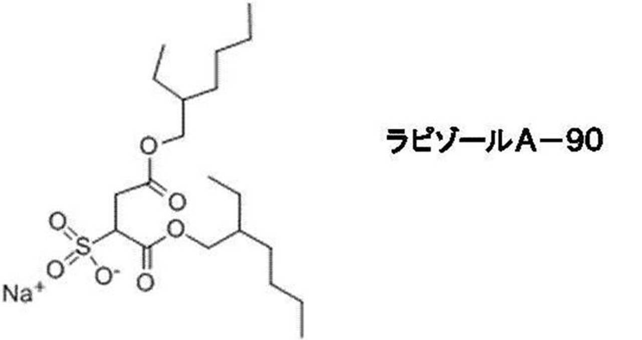
(硫酸エステル型)
・ラウリル硫酸ナトリウム(C12H25OSO3Na)
・ミリスチル硫酸ナトリウム(C14H29OSO3Na)
・ラウレス硫酸ナトリウム(C12H25(CH2CH2O)nOSO3Na、w:Sodium laureth sulfate)
・ポリオキシエチレンアルキルフェノールスルホン酸ナトリウム(C8H17C6H4O[CH2CH2O]3SO3Na)
・ラウリル硫酸アンモニウム(C12H25OSO3NH4、w:Ammonium lauryl sulfate)
(リン酸エステル型)
・ラウリルリン酸(C12H25OPO(OH)2)
・ラウリルリン酸ナトリウム(C12H25OPOOHONa)
・ラウリルリン酸カリウム(C12H25OPOOHOK)
・ラウリル硫酸ナトリウム(C12H25OSO3Na)
・ミリスチル硫酸ナトリウム(C14H29OSO3Na)
・ラウレス硫酸ナトリウム(C12H25(CH2CH2O)nOSO3Na、w:Sodium laureth sulfate)
・ポリオキシエチレンアルキルフェノールスルホン酸ナトリウム(C8H17C6H4O[CH2CH2O]3SO3Na)
・ラウリル硫酸アンモニウム(C12H25OSO3NH4、w:Ammonium lauryl sulfate)
(リン酸エステル型)
・ラウリルリン酸(C12H25OPO(OH)2)
・ラウリルリン酸ナトリウム(C12H25OPOOHONa)
・ラウリルリン酸カリウム(C12H25OPOOHOK)
-2.陽イオン系界面活性剤-
(第4級アンモニウム塩型)
・塩化ドデシルジメチルベンジルアンモニウム(C12H25N+(CH3)2CH2C6H5Cl)
・塩化オクチルトリメチルアンモニウム(C8H17N+(CH3)3Cl)
・塩化デシルトリメチルアンモニウム(C10H21N+(CH3)3Cl)
・塩化ドデシルトリメチルアンモニウム(C12H25N+(CH3)3Cl)
・塩化テトラデシルトリメチルアンモニウム(C14H29N+(CH3)3Cl)
・塩化セチルトリメチルアンモニウム (CTAC)(C16H33N+(CH3)3Cl)
・塩化ステアリルトリメチルアンモニウム(C18H37N+(CH3)3Cl)
・臭化ヘキサデシルトリメチルアンモニウム (CTAB)(C16H33N+(CH3)3Br)
・塩化ベンジルトリメチルアンモニウム(C6H5CH2N+(CH3)3Cl)
・塩化ベンジルトリエチルアンモニウム(C6H5CH2N+(C2H5)3Cl)
・塩化ベンザルコニウム(C6H5CH2N+(CH3)2RCl〔R:炭素数8~17のアルキル〕)
・臭化ベンザルコニウム(C6H5CH2N+(CH3)2RBr〔R:炭素数8~17のアルキル〕)
・塩化ベンゼトニウム(C6H5CH2N+(CH3)2(CH2CH2O)2C6H4C8H17Cl)
・塩化ジアルキルジメチルアンモニウム(RN+R(CH3)2Cl〔R:炭素数3~20のアルキル〕)
・塩化ジデシルジメチルアンモニウム(C10H21N+C10H21(CH3)2Cl)
・塩化ジステアリルジメチルアンモニウム(C18H37N+C18H37(CH3)2Cl、w:Dimethyldioctadecylammonium chloride)
(アルキルアミン塩型)
・モノメチルアミン塩酸塩(CH3NH2・HCl)
・ジメチルアミン塩酸塩((CH3)2NH・HCl)
・トリメチルアミン塩酸塩((CH3)3N・HCl)
(ピリジン環を有する物質)
・塩化ブチルピリジニウム(C5H5N+C4H9Cl)
・塩化ドデシルピリジニウム(C5H5N+C12H25Cl)
・塩化セチルピリジニウム(C5H5N+C16H33Cl)
(第4級アンモニウム塩型)
・塩化ドデシルジメチルベンジルアンモニウム(C12H25N+(CH3)2CH2C6H5Cl)
・塩化オクチルトリメチルアンモニウム(C8H17N+(CH3)3Cl)
・塩化デシルトリメチルアンモニウム(C10H21N+(CH3)3Cl)
・塩化ドデシルトリメチルアンモニウム(C12H25N+(CH3)3Cl)
・塩化テトラデシルトリメチルアンモニウム(C14H29N+(CH3)3Cl)
・塩化セチルトリメチルアンモニウム (CTAC)(C16H33N+(CH3)3Cl)
・塩化ステアリルトリメチルアンモニウム(C18H37N+(CH3)3Cl)
・臭化ヘキサデシルトリメチルアンモニウム (CTAB)(C16H33N+(CH3)3Br)
・塩化ベンジルトリメチルアンモニウム(C6H5CH2N+(CH3)3Cl)
・塩化ベンジルトリエチルアンモニウム(C6H5CH2N+(C2H5)3Cl)
・塩化ベンザルコニウム(C6H5CH2N+(CH3)2RCl〔R:炭素数8~17のアルキル〕)
・臭化ベンザルコニウム(C6H5CH2N+(CH3)2RBr〔R:炭素数8~17のアルキル〕)
・塩化ベンゼトニウム(C6H5CH2N+(CH3)2(CH2CH2O)2C6H4C8H17Cl)
・塩化ジアルキルジメチルアンモニウム(RN+R(CH3)2Cl〔R:炭素数3~20のアルキル〕)
・塩化ジデシルジメチルアンモニウム(C10H21N+C10H21(CH3)2Cl)
・塩化ジステアリルジメチルアンモニウム(C18H37N+C18H37(CH3)2Cl、w:Dimethyldioctadecylammonium chloride)
(アルキルアミン塩型)
・モノメチルアミン塩酸塩(CH3NH2・HCl)
・ジメチルアミン塩酸塩((CH3)2NH・HCl)
・トリメチルアミン塩酸塩((CH3)3N・HCl)
(ピリジン環を有する物質)
・塩化ブチルピリジニウム(C5H5N+C4H9Cl)
・塩化ドデシルピリジニウム(C5H5N+C12H25Cl)
・塩化セチルピリジニウム(C5H5N+C16H33Cl)
-3.非イオン系界面活性剤-
(エステル型)
・ラウリン酸グリセリン(C11H23COOCH2CH(OH)CH2OH、w:Glyceryl laurate)
・モノステアリン酸グリセリン(C17H35COOCH2CH(OH)CH2OH)
・ソルビタン脂肪酸エステル(RCOOCH2CH(CHOH)3CH2O〔R:炭素数3~20のアルキル〕)
・ショ糖脂肪酸エステル(RCOOC12H21O10〔R:炭素数3~20のアルキル〕)
(エーテル型)
・ポリオキシエチレンアルキルエーテル(RO(CH2CH2O)nH〔R:炭素数3~20のアルキル〕)
・ペンタエチレングリコールモノドデシルエーテル(C12H25O(CH2CH2O)5H、w:Pentaethylene glycol monododecyl ether)
・オクタエチレングリコールモノドデシルエーテル(C12H25O(CH2CH2O)8H、w:Octaethylene glycol monododecyl ether)
・ポリオキシエチレンアルキルフェニルエーテル(RC6H4O(CH2CH2O)nH〔R:炭素数3~20のアルキル〕)
・ノノキシノール(C9H19C6H4O(CH2CH2O)nH、w:Nonoxynols)
・ノノキシノール-9(C9H19C6H4O(CH2CH2O)9H、w:Nonoxynol-9)
・ポリオキシエチレンポリオキシプロピレングリコール(H(OCH2CH2)l(OC3H6)m(OCH2CH2)nOH)
(エステルエーテル型)
・ポリオキシエチレンソルビタン脂肪酸エステル
・ポリオキシエチレンヘキシタン脂肪酸エステル
・ソルビタン脂肪酸エステルポリエチレングリコール
(アルカノールアミド型)
・ラウリン酸ジエタノールアミド(C11H23CON(C2H4OH)2)
・オレイン酸ジエタノールアミド(C17H33CON(C2H4OH)2)
・ステアリン酸ジエタノールアミド(C17H35CON(C2H4OH)2)
・コカミドDEA (CH3(CH2)nCON(C2H4OH)2、w:Cocamide DEA)
(アルキルグリコシド)
・オクチルグルコシド(C8H17C6H11O6)
・デシルグルコシド(C10H21C6H11O6、w:Decyl glucoside)
・ラウリルグルコシド(C12H25C6H11O6、w:Lauryl glucoside)
(高級アルコール)
・セタノール(C16H33OH、w:Cetyl alcohol)
・ステアリルアルコール(C18H37OH、w:Stearyl alcohol)
・オレイルアルコール(CH3(CH2)7CH=CH(CH2)8OH、w:Oleyl alcohol)
(エステル型)
・ラウリン酸グリセリン(C11H23COOCH2CH(OH)CH2OH、w:Glyceryl laurate)
・モノステアリン酸グリセリン(C17H35COOCH2CH(OH)CH2OH)
・ソルビタン脂肪酸エステル(RCOOCH2CH(CHOH)3CH2O〔R:炭素数3~20のアルキル〕)
・ショ糖脂肪酸エステル(RCOOC12H21O10〔R:炭素数3~20のアルキル〕)
(エーテル型)
・ポリオキシエチレンアルキルエーテル(RO(CH2CH2O)nH〔R:炭素数3~20のアルキル〕)
・ペンタエチレングリコールモノドデシルエーテル(C12H25O(CH2CH2O)5H、w:Pentaethylene glycol monododecyl ether)
・オクタエチレングリコールモノドデシルエーテル(C12H25O(CH2CH2O)8H、w:Octaethylene glycol monododecyl ether)
・ポリオキシエチレンアルキルフェニルエーテル(RC6H4O(CH2CH2O)nH〔R:炭素数3~20のアルキル〕)
・ノノキシノール(C9H19C6H4O(CH2CH2O)nH、w:Nonoxynols)
・ノノキシノール-9(C9H19C6H4O(CH2CH2O)9H、w:Nonoxynol-9)
・ポリオキシエチレンポリオキシプロピレングリコール(H(OCH2CH2)l(OC3H6)m(OCH2CH2)nOH)
(エステルエーテル型)
・ポリオキシエチレンソルビタン脂肪酸エステル
・ポリオキシエチレンヘキシタン脂肪酸エステル
・ソルビタン脂肪酸エステルポリエチレングリコール
(アルカノールアミド型)
・ラウリン酸ジエタノールアミド(C11H23CON(C2H4OH)2)
・オレイン酸ジエタノールアミド(C17H33CON(C2H4OH)2)
・ステアリン酸ジエタノールアミド(C17H35CON(C2H4OH)2)
・コカミドDEA (CH3(CH2)nCON(C2H4OH)2、w:Cocamide DEA)
(アルキルグリコシド)
・オクチルグルコシド(C8H17C6H11O6)
・デシルグルコシド(C10H21C6H11O6、w:Decyl glucoside)
・ラウリルグルコシド(C12H25C6H11O6、w:Lauryl glucoside)
(高級アルコール)
・セタノール(C16H33OH、w:Cetyl alcohol)
・ステアリルアルコール(C18H37OH、w:Stearyl alcohol)
・オレイルアルコール(CH3(CH2)7CH=CH(CH2)8OH、w:Oleyl alcohol)
-4.両性界面活性剤-
(アルキルベタイン型)
・ラウリルジメチルアミノ酢酸ベタイン(C12H25N+(CH3)2CH2COO-)
・ステアリルジメチルアミノ酢酸ベタイン(C18H37N+(CH3)2CH2COO-)
・ドデシルアミノメチルジメチルスルホプロピルベタイン(C12H25N+(CH3)2(CH2)3SO3 -)
・オクタデシルアミノメチルジメチルスルホプロピルベタイン(C18H37N+(CH3)2(CH2)3SO3 -)
(脂肪酸アミドプロピルベタイン型)
・コカミドプロピルベタイン(C11H23CONH(CH2)3N+(CH3)2CH2COO-、w:Cocamidopropyl betaine)
・コカミドプロピルヒドロキシスルタイン(C11H23CONH(CH2)3N+(CH3)2CH2CHOHCH2SO3 -)
(アルキルイミダゾール型)
・2-アルキル-N-カルボキシメチル-N-ヒドロキシエチルイミダゾリニウムベタイン(RC3H4N2(C2H4OH)CH2COO-〔R:炭素数3~20のアルキル〕)
(アミノ酸型)
・ラウロイルグルタミン酸ナトリウム(C11H23CON(C2H4COOH)HCHCOONa)
・ラウロイルグルタミン酸カリウム(C11H23CON(C2H4COOH)HCHCOOK)
・ラウロイルメチル-β-アラニン(C11H23CONH(C2H4COOCH3)
(アミンオキシド型)
・ラウリルジメチルアミン-N-オキシド(C12H25N+(CH3)2O-)
・オレイルジメチルアミン-N-オキシド(C18H37N+(CH3)2O-)
(アルキルベタイン型)
・ラウリルジメチルアミノ酢酸ベタイン(C12H25N+(CH3)2CH2COO-)
・ステアリルジメチルアミノ酢酸ベタイン(C18H37N+(CH3)2CH2COO-)
・ドデシルアミノメチルジメチルスルホプロピルベタイン(C12H25N+(CH3)2(CH2)3SO3 -)
・オクタデシルアミノメチルジメチルスルホプロピルベタイン(C18H37N+(CH3)2(CH2)3SO3 -)
(脂肪酸アミドプロピルベタイン型)
・コカミドプロピルベタイン(C11H23CONH(CH2)3N+(CH3)2CH2COO-、w:Cocamidopropyl betaine)
・コカミドプロピルヒドロキシスルタイン(C11H23CONH(CH2)3N+(CH3)2CH2CHOHCH2SO3 -)
(アルキルイミダゾール型)
・2-アルキル-N-カルボキシメチル-N-ヒドロキシエチルイミダゾリニウムベタイン(RC3H4N2(C2H4OH)CH2COO-〔R:炭素数3~20のアルキル〕)
(アミノ酸型)
・ラウロイルグルタミン酸ナトリウム(C11H23CON(C2H4COOH)HCHCOONa)
・ラウロイルグルタミン酸カリウム(C11H23CON(C2H4COOH)HCHCOOK)
・ラウロイルメチル-β-アラニン(C11H23CONH(C2H4COOCH3)
(アミンオキシド型)
・ラウリルジメチルアミン-N-オキシド(C12H25N+(CH3)2O-)
・オレイルジメチルアミン-N-オキシド(C18H37N+(CH3)2O-)
炭素数3~20のアルキル基又は炭素数3~20のフッ化アルキル基を有する界面活性剤の分子量としては、60~2000の範囲が好ましく、80~1500の範囲がより好ましい。分子量が60以上であると、膜面として均一にブロッキング抑制できる点で有利である。分子量が2000以下であることで、ブロッキングを抑制しつつ、酸性ガス分離性をも確保することができる。
「炭素数3~20のアルキル基又は炭素数3~20のフッ化アルキル基を有する界面活性剤」を含有する促進輸送膜52Aを形成する場合、該界面活性剤の含有量としては、促進輸送膜52Aの全固形分に対して、0.01質量%~10質量%であることが好ましく、更には0.01~3質量%であることが好ましい。「炭素数3~20のアルキル基又は炭素数3~20のフッ化アルキル基を有する界面活性剤」の含有量が0.01質量%以上であることで、ブロッキングの発生抑止の効果により優れる。また、該界面活性剤の含有量が10質量%以下であると、二酸化炭素ガス44の分離性が良好に保たれる。
[シロキサン構造を有する化合物]
シロキサン構造を有する化合物は、促進輸送膜52Aを塗布により塗膜形成した際の膜表面に該表面を覆うように偏在しやすく、ブロッキングの発生抑止に効果がある。シロキサン構造とは、「-Si-O-Si-」で示されるシロキサン骨格を部分構造として有していれば、特に制限はない。
シロキサン構造を有する化合物は、促進輸送膜52Aを塗布により塗膜形成した際の膜表面に該表面を覆うように偏在しやすく、ブロッキングの発生抑止に効果がある。シロキサン構造とは、「-Si-O-Si-」で示されるシロキサン骨格を部分構造として有していれば、特に制限はない。
シロキサン構造を有する化合物としては、促進輸送膜52Aを塗布により塗膜形成したときの表面偏析性を高める観点から、側鎖にシロキサン構造を有する構造単位を含む化合物が好ましい。
分子内にシロキサン構造を導入する際に有用なシロキサン化合物は、上市されている市販品より入手することができ、例えば、信越化学工業社製のX-22-173DX、X-22-173BXなどの片末端反応性シリコーンが挙げられる。
また、このような化合物は、反応性末端を有するシロキサンとカチオン重合性基を持つ化合物を反応させることで合成することができる。例えば、チッソ社製のサイラプレーンシリーズFM-0411,同FM-0421,同FM-0425等の片末端水酸基を持つ化合物とエピクロロヒドリンとから合成することや、特開平11-80315号公報に記載の方法にて合成することができる。
また、このような化合物は、反応性末端を有するシロキサンとカチオン重合性基を持つ化合物を反応させることで合成することができる。例えば、チッソ社製のサイラプレーンシリーズFM-0411,同FM-0421,同FM-0425等の片末端水酸基を持つ化合物とエピクロロヒドリンとから合成することや、特開平11-80315号公報に記載の方法にて合成することができる。
シロキサン構造を有する化合物を含む促進輸送膜52Aを形成する場合、シロキサン構造を有する化合物の含有量としては、促進輸送膜52Aの全固形分に対して、0.01質量%~10質量%であることが好ましく、更には0.01~3質量%であることが好ましい。シロキサン構造を有する化合物の含有量が0.01質量%以上であることで、ブロッキングの発生抑止の効果により優れる。また、特定化合物の含有量が10質量%以下であると、二酸化炭素等の酸性ガスの分離性が良好に保たれる。
(ポリマー粒子)
ポリマー粒子としては、例えば、ポリオレフィン(例:ポリエチレン、ポリプロピレン、ポリメチルペンテンなど)、ポリメタクリル酸メチル、ポリスチレン、熱可塑性エラストマー、シリコーンなどの粒子が好適に挙げられる。中でも、均一にブロッキング抑止できる点で、ポリオレフィンの粒子が好ましい。
ポリマー粒子としては、例えば、ポリオレフィン(例:ポリエチレン、ポリプロピレン、ポリメチルペンテンなど)、ポリメタクリル酸メチル、ポリスチレン、熱可塑性エラストマー、シリコーンなどの粒子が好適に挙げられる。中でも、均一にブロッキング抑止できる点で、ポリオレフィンの粒子が好ましい。
ポリマー粒子の平均粒子径は、0.01μm~1000μmの範囲とすることが好ましい。ポリマー粒子の粒子径が0.01μm以上であると、粒子が密に詰まりすぎないために、塗膜形成したときの膜表面に占める面積を分離性能を下げずに確保することができる。また、ポリマー粒子の平均粒子径が1000μm以下であると、塗膜形成したときの膜表面にポリマーが多く存在し過ぎず、二酸化炭素透過性が低下しないとともに、ポリマー粒子が脱落しにくい。中でも、ポリマー粒子の平均粒子径としては、0.02μm~750μmの範囲がより好ましく、更に好ましくは0.03μm~500μmの範囲であり、特に好ましくは0.1μm~50μmの範囲である。
ポリマー粒子の粒子径は、大塚電子社製のFPAR1000を用いて測定される値である。
ポリマー粒子の粒子径は、大塚電子社製のFPAR1000を用いて測定される値である。
ポリマー粒子の比重は、0.5g/cm3~1.3g/cm3の範囲とすることが好ましい。ポリマー粒子の比重が0.5g/cm3以上であると、膜表面を閉塞しにくく、二酸化炭素の透過性が損なわれにくい。また、ポリマー粒子の比重が1.3g/cm3以下であると、塗布液中に沈降しにくくなり、塗膜形成したときの膜表面にポリマーが存在しやすくなることで、ブロッキング抑止効果が良好になる。中でも、ポリマー粒子の比重としては、0.52g/cm3~1.28g/cm3の範囲がより好ましく、更に好ましくは0.55g/cm3~1.27g/cm3の範囲である。
ポリマー粒子は、例えば、水性媒体中にポリマーが液体状態で分散された乳化物(エマルション)、及び水性媒体中にポリマーが固体状態で分散された分散物(サスペンション)の形態で使用することができる。
ポリマー粒子は、上市されている市販品を用いてもよく、例えば、三井化学工業社製のケミパールw-308、同w-400、同w-100、同wp-100、同A-100などを使用することができる。
促進輸送膜52Aがポリマー粒子を含有する場合、促進輸送膜52A中における総含有量は、促進輸送膜52Aの表面におけるポリマー粒子の占有面積が0.1%~60%となる量が好ましい。ポリマー粒子による占有面積が0.1%以上であることで、ブロッキングの発生抑止の効果により優れる。また、ポリマー粒子による占有面積が60%以下であると、ブロッキングが抑止しつつも、酸性ガス分離性を良好に保つことができる。ポリマー粒子の占有面積としては、0.5%~30%であるのがより好ましく、1%~10%であるのが更に好ましい。
占有面積は、走査型電子顕微鏡(JSM6610、JEOL社製)を用い、単位面積あたりの粒子被覆率を画像解析することにより求められる。
占有面積は、走査型電子顕微鏡(JSM6610、JEOL社製)を用い、単位面積あたりの粒子被覆率を画像解析することにより求められる。
ポリマー粒子を用いて促進輸送膜52Aを塗布形成する場合、ポリマー粒子は比重が低いため、ポリマー粒子を含有する塗布液を用いて促進輸送膜52Aを形成し乾燥する過程において、塗膜表面にポリマー粒子が偏在する。これにより、表面のみに付与するといった特段の処理を行なわなくとも、ポリマー粒子が表面に偏在してブロッキングを防止する。
また、促進輸送膜52Aは、ポリマー粒子や上記の特定化合物を含有する第1の塗布液と、ポリマー粒子や特定化合物を含有しない第2の塗布液とをそれぞれ調製し、多孔質支持体52B上に第2の塗布液、第1の塗布液の重層順になるように重層塗布することによって、ポリマー粒子や特定化合物を膜面に偏在させてなる層として形成することができる。
これらの化合物やポリマー粒子は、いずれも水溶性高分子化合物層を構成する他の成分と相溶しないために、水溶性高分子化合物層が本来有する分離能を損なうことはない。
また、促進輸送膜52Aは、ポリマー粒子や上記の特定化合物を含有する第1の塗布液と、ポリマー粒子や特定化合物を含有しない第2の塗布液とをそれぞれ調製し、多孔質支持体52B上に第2の塗布液、第1の塗布液の重層順になるように重層塗布することによって、ポリマー粒子や特定化合物を膜面に偏在させてなる層として形成することができる。
これらの化合物やポリマー粒子は、いずれも水溶性高分子化合物層を構成する他の成分と相溶しないために、水溶性高分子化合物層が本来有する分離能を損なうことはない。
(多孔質支持体)
促進輸送膜52Aと共に二酸化炭素ガス分離部材52を構成する多孔質支持体52Bは、供給ガス流路用部材50と同様のものを用いることができる。
促進輸送膜52Aと共に二酸化炭素ガス分離部材52を構成する多孔質支持体52Bは、供給ガス流路用部材50と同様のものを用いることができる。
(透過ガス流路用部材)
二酸化炭素ガス分離部材52と共に積層体16を構成する透過ガス流路用部材54は、キャリアと反応して二酸化炭素ガス分離部材52を透過した二酸化炭素ガス44を貫通孔32Aに向かって案内する部材である。透過ガス流路用部材54は、スペーサーとしての機能を有し、また透過した二酸化炭素ガス44を透過ガス流路用部材54よりも内側に流す機能を有し、さらに後述する接着剤56を浸透させる機能を有するように、透過ガス流路用部材54は、供給ガス流路用部材50と同様に、ネット状の部材が好ましい。透過ガス流路用部材54の材質は、供給ガス流路用部材50と同様のものを用いることができる。
二酸化炭素ガス分離部材52と共に積層体16を構成する透過ガス流路用部材54は、キャリアと反応して二酸化炭素ガス分離部材52を透過した二酸化炭素ガス44を貫通孔32Aに向かって案内する部材である。透過ガス流路用部材54は、スペーサーとしての機能を有し、また透過した二酸化炭素ガス44を透過ガス流路用部材54よりも内側に流す機能を有し、さらに後述する接着剤56を浸透させる機能を有するように、透過ガス流路用部材54は、供給ガス流路用部材50と同様に、ネット状の部材が好ましい。透過ガス流路用部材54の材質は、供給ガス流路用部材50と同様のものを用いることができる。
透過ガス流路用部材54の幅方向両端部は接着剤58で封止されている一方で、透過ガス流路用部材54の巻き終わり端部54Aはスイープガス30が導入されるように開放されている。なお、接着剤58の材料は、接着剤56と同様のものを用いることができる。
<分離モジュールの製造方法>
次に、本発明の実施形態に係る分離システム11の製造方法について説明する。図4A~図4Mは、図1に示す分離システム11の製造工程図である。
次に、本発明の実施形態に係る分離システム11の製造方法について説明する。図4A~図4Mは、図1に示す分離システム11の製造工程図である。
本発明の実施形態に係る分離システム11の製造方法では、まず、図4Aに示すように、カプトンテープ又は接着剤等の固定部材60で、長尺状の透過ガス流路用部材54の先端部(巻き始め端部)を中心管32の外周面に固定する。
次に、図4Bに示すように、促進輸送膜52Aを内側に二つ折りした長尺状の二酸化炭素ガス分離部材52に長尺状の供給ガス流路用部材50を挟み込む。なお、二酸化炭素ガス分離部材52を二つ折りする際は、二酸化炭素ガス分離部材52を二分割してもよいが、図4Bに示すように、ずらして折ってもよい。
また、二酸化炭素ガス分離部材52を二つ折りする際、供給ガス流路用部材50の巻き終わり端部を接着剤56で封止し、且つ、供給ガス流路用部材50と二酸化炭素ガス分離部材52を接着させる。
また、二酸化炭素ガス分離部材52をずらして二つ折りする場合、二つ折りした中で長い方の二酸化炭素ガス分離部材52は、供給ガス流路用部材50の巻き終わり端部よりも延伸しており、延伸先の端部(二酸化炭素ガス分離部材52の巻き終わり端部)の内側表面にも接着剤62を塗布する。なお、二酸化炭素ガス分離部材52を二分割して二つ折りする場合接着剤62は不要である。
次に、図4Cに示すように、二つ折りした二酸化炭素ガス分離部材52の中で短い方の二酸化炭素ガス分離部材52の外側表面における幅方向両端部に接着剤58を塗布する。
次に、図4Dに示すように、中心管32に固定した透過ガス流路用部材54の長手方向中央部表面に、接着剤58及び62を介して、供給ガス流路用部材50を挟んだ二酸化炭素ガス分離部材52を貼り付ける。ここで、接着剤58は透過ガス流路用部材54の内部にまで浸透し、後述する図4Eに示す接着剤58の浸透も合わせて透過ガス流路用部材54の幅方向両端部を封止する。一方で、接着剤62は、透過ガス流路用部材54には浸透せず、供給ガス流路用部材50側にスイープガス30が浸入するのを防ぐために二酸化炭素ガス分離部材52と透過ガス流路用部材54を接着するに留まっている。これにより供給ガス流路用部材50、二酸化炭素ガス分離部材52、透過ガス流路用部材54を含む積層体26が形成される。
次に、図4Eに示すように、透過ガス流路用部材54に貼り付けた二酸化炭素ガス分離部材52の表面(貼り付け面とは逆の面)に対して、幅方向両端部に接着剤58を塗布する。
次に、透過ガス流路用部材54で貫通孔32Aを覆うように、中心管32に積層体26を図中矢印C方向に多重に巻き付ける。
次に、図4Fに示すように、積層体26から延伸する透過ガス流路用部材54にテンションをかける。そして、積層体26周辺の透過ガス流路用部材54にホットメルト70を塗布する。
次に、図4Gに示すように、積層体26から延伸する透過ガス流路用部材54をさらに積層体26に巻いて、ホットメルト70を介して固定し、ホットメルト70より先に延伸する透過ガス流路用部材54をカットする。なお、ホットメルト70を塗布する際、透過ガス流路用部材54の巻き終わり端部54C全体が封止されないように量及び面積を調整する。また、巻き終わり端部54C全体が封止されないように、透過ガス流路用部材54の幅方向両端部にホットメルト70を塗布することが好ましい。また、巻き終わり端部54C全体が封止されないように、ホットメルト70の塗布面積は小さいほど好ましい。
次に、図4Hに示すように、中心管32に巻き付けた積層体26の最外周に被覆部材40としてのカプトンテープ40Aを巻き付ける。なお、この際、積層体26及びカプトンテープ40Aの幅方向の長さが長い場合には、その幅方向両端部をカットするようにしてもよい。この場合、透過ガス流路用部材54の幅方向両端部に浸透させる接着剤58もカットを考慮して、当該幅方向両端部の内側寄りに塗布するようにする。
次に、図4Iに示すように、カプトンテープ40Aにスイープガス30の導入口40Cを形成する。この際、透過ガス流路用部材54の巻き終わり端部54Aが露出するように導入口40Cを形成する。
次に、図4Jに示すように、テレスコープ防止板42を積層体26及びカプトンテープ40Aの両側端部に取り付ける。
次に、図4Kに示すように、導入口40Cの少なくとも一部が露出するようにカプトンテープ40Aにおける管軸方向Aの中央部を挟んで、カプトンテープ40Aにおける管軸方向Aの外周面両端部をカバー40Bで覆う。
以上の工程を経ることにより、本発明の実施形態に係る分離モジュール14が得られる。
次に、図4Lに示すように、分離モジュール14におけるテレスコープ防止板42の外周面にOリング15を嵌め込む。
最後に、図4Mに示すように、Oリング15を介して分離モジュール14を圧力容器12の収納部16の内周面に嵌め込んで収納部16内に収納する。
以上の工程を経ることにより、本発明の実施形態に係る分離システム11が得られる。
<作用>
次に、本発明の実施形態の参考例に係る作用について説明する。
次に、本発明の実施形態の参考例に係る作用について説明する。
図7は、本発明の実施形態の参考例に係る分離モジュールにおいて、積層体26を正面に広げた状態を示す模式図である。
参考例に係る分離モジュール100は、中心管32の外周面に積層体26が巻きつけられている。積層体26中の透過ガス流路用部材102は、実施形態に係る透過ガス流路用部材54と異なり、幅方向両端部102Aだけでなく巻き終わり端部102Bも接着剤104で封止されている。また、中心管32の中央内部には、当該中央内部を遮断する仕切部材106が設けられている。
このような構成の分離モジュール100では、一端部側から積層体26に二酸化炭素ガス44を含む原料ガス28(又は残余のガス46)が供給される。原料ガス28が供給されると、促進輸送膜52Aの構成により、原料ガス28を二酸化炭素ガス44と残余のガス46に分離して二酸化炭素ガス44は透過ガス流路用部材102及び貫通孔32Aを通って中心管32から、残余のガス46は他端部側の積層体26から別々に排出する。
この際、スイープガス30が、中心管32の一端部側から供給され、仕切部材106に当り、貫通孔32Aを通って、透過ガス流路用部材102内に流入する。流入したスイープガス30は、透過ガス流路用部材102内に流れる二酸化炭素ガス44をスイープしながら、二酸化炭素ガス44とともに仕切部材106を越えて、再び貫通孔32Aを通って、中心管32の他端部側から排出される。
しかしながら、透過ガス流路用部材内の、例えば幅方向両端部102Aの接着剤104による封止部分と巻き終わり端部102Bの接着剤104による封止部分との交差する近傍等の箇所にスイープガス30が行き渡らないため、同箇所で二酸化炭素ガス44の滞留が起こり、二酸化炭素ガス44の分離効率を十分に高めることができない。
そこで、本発明の実施形態に係る作用について図1、図2、図3及び図5を用いて説明する。
図5は、本発明の実施形態に係る分離モジュール14において、積層体26を正面に広げた状態を示す模式図である。
まず、図1に示すように、分離システム11では、原料ガス供給口18から原料ガス28が圧力容器12の収納部16内に供給される。収納部16内に供給された原料ガス28は、分離モジュール14の積層体26の一方の側端部26Aに供給される。また、スイープガス供給口20からスイープガス30が圧力容器12の収納部16内に、原料ガス28の供給方向とは略直角方向で供給される。収納部16内に供給されたスイープガス30は、分離モジュール14の被覆部材40に形成された導入口40Cに供給される。
ここで、分離モジュール14の積層体26は、図2に示すように、被覆部材40によって覆われており、また被覆部材40の導入口40Cも外部からスイープガス30が導入される。このため、そのスイープガス30のガス圧により、積層体26の一方の側端部26Aから供給ガス流路用部材50に供給された原料ガス28は、図3に示すように、原則途中で外側に流れ出すことなく、供給ガス流路用部材50を通過して収納部16へ排出され、原料ガス排出口22から圧力容器12の外部へ排出される。この供給ガス流路用部材50を通過する原料ガス28中の二酸化炭素ガス44は、二酸化炭素ガス分離部材52の促進輸送膜52Aを透過して分離され、透過ガス流路用部材54及び貫通孔32Aを介して中心管32に集積され、中心管32の排出口32Bを介してスイープガス排出口24から圧力容器12の外部へ排出される。
そして、透過ガス流路用部材54を二酸化炭素ガス44が流れる際、被覆部材40(カプトンテープ40A)の導入口40Cから開放された透過ガス流路用部材54の巻き終わり端部54Aを介して透過ガス流路用部材54の内部へスイープガス30が導入され中心管32に向かうため、図5に示すように、スイープガス30が二酸化炭素ガス44をスイープしながら透過ガス流路用部材54の内部に行き渡る。これにより、透過ガス流路用部材54の内部での二酸化炭素ガス44の滞留を抑制して、二酸化炭素ガス44の分離効率を高くすることができる。
また、図3に示すように、本発明の実施形態に係る分離モジュール14によれば、透過ガス流路用部材54の幅方向両端部は封止されているため、この幅方向両端部からスイープガス30や二酸化炭素ガス44が流出することがなく、透過ガス流路用部材54の内部をまんべんなく流れる。
また、図3に示すように、本発明の実施形態に係る分離モジュール14によれば、スイープガス30が被覆部材40の導入口40Cを介して開放された透過ガス流路用部材54の巻き終わり端部54Aから導入されても、供給ガス流路用部材50の巻き終わり端部は接着剤56で封止されているため供給ガス流路用部材50の内部にはスイープガス30が導入されない。したがって、スイープガス30によって、供給ガス流路用部材50に供給される原料ガス28が乱されてしまうことを回避できる。
また、図2に示すように、本発明の実施形態に係る分離モジュール14によれば、導入口40Cからは、透過ガス流路用部材54の巻き終わり端部54Aが露出しているため、スイープガス30が被覆部材40の内部を通ることなく巻き終わり端部54Aへ導入され易い。
また、図1に示すように、本発明の実施形態に係る分離システム11によれば、原料ガス供給口18は収納部16の一方の側端部16Aに設けられ、スイープガス供給口20は収納部16の外周部16Bに設けられているため、原料ガス28とスイープガス30の供給方向が略直角となるので、スイープガス30が透過ガス流路用部材54内に流れる二酸化炭素ガス44をスイープし易くなる。
また、図1に示すように、本発明の実施形態に係る分離システム群10によれば、各圧力容器12のスイープガス供給口20のうち、一のスイープガス供給口20はスイープガス供給源36に繋がれ、残りのスイープガス供給口20は他の圧力容器12のスイープガス排出口24に繋がれている。このため、各圧力容器12のスイープガス供給口20に個別のスイープガス供給源36を繋げる場合に比べて、スイープガス供給源36を削減することができる。
<変形例>
なお、本発明を複数の実施形態について詳細に説明したが、本発明はかかる実施形態に限定されるものではなく、本発明の範囲内にて他の種々の実施形態が可能であることは当業者にとって明らかである。また、上述の実施形態や下記の変形例は、適宜、組み合わせて実施可能である。
なお、本発明を複数の実施形態について詳細に説明したが、本発明はかかる実施形態に限定されるものではなく、本発明の範囲内にて他の種々の実施形態が可能であることは当業者にとって明らかである。また、上述の実施形態や下記の変形例は、適宜、組み合わせて実施可能である。
例えば、分離部材として促進輸送膜52Aを用いる場合を説明したが、他の分離部材を用いてもよい。他の分離膜としては、例えば、溶解拡散型の膜やクヌーセン拡散型の膜、分子ふるい型の膜、表面拡散型の膜などが挙げられる。
また、分離部材が分離する原料ガス28のガス成分も二酸化炭素44に限られず、水素等の他の気体であってもよい。
また、分離モジュール14では、原料ガス28の供給方向と中心管32からのスイープガス30及び二酸化炭素ガス44の排出方向が逆である場合を説明したが、供給方向と排出方向が同じであってもよい。
また、本実施形態のように、スイープガス30が導入口40Cから導入される場合、二酸化炭素ガス分離部材52の表裏の全圧をかなり近くできるので、積層体16からのリークが抑制され、供給ガス流路用部材50や透過ガス流路用部材54の流れ方向を取り替えることができる。
また、本実施形態のように、スイープガス30が導入口40Cから導入される場合、二酸化炭素ガス分離部材52の表裏の全圧をかなり近くできるので、積層体16からのリークが抑制され、供給ガス流路用部材50や透過ガス流路用部材54の流れ方向を取り替えることができる。
また、分離モジュール14では、導入口40Cから透過ガス流路用部材54の巻き終わり端部54Aが露出している場合を説明したが、露出していなくてもよい。この場合であっても、スイープガス30は導入口40Cから被覆部材40(カプトンテープ40A)の内部を通って、導入口40Cに流れ込む。
また、供給ガス流路用部材50の巻き終わり端部は接着剤56で封止されている場合を説明したが、開放されていてもよい。ただし、供給ガス流路用部材50に供給される原料ガス28を乱さないという観点から、供給ガス流路用部材50の巻き終わり端部は封止した方が好ましい。なお、封止の仕方は、接着剤を浸透させる方法に限定されず、両面テープを貼り付ける方法等であってもよい。
また、カプトンテープ40Aを覆うカバー40Bは、導入口40Cが露出するようにカプトンテープ40Aにおける管軸方向Aの中央部を挟んで、カプトンテープ40Aにおける管軸方向Aの外周面両端部を覆っている場合を説明した。しかしながら、カバー40Bの構成は上記に限定されない。例えば、カバー40Bの代わりに図6に示すようなカバー40Dを用いてもよい。このカバー40Dは、原則カプトンテープ40Aの全域を覆い、導入口40Cを含む一部のカプトンテープ40Aが露出するように、導入口40Eが形成されている。
また、被覆部材40は二層構造である場合を説明したが、一層であっても三層以上であってもよい。
以下、本発明について実施例に基づきさらに詳細に説明するが、本発明はこれらの実施例によって何ら限定して解釈されるものではない。
<分離モジュール1>
クラストマーAP-20(クラレ社製):2.4重量%、25%グルタルアルデヒド水溶液(Wako社製):0.01重量%を含む水溶液に、1M塩酸をpH1になるまで添加し、架橋後、キャリアとしての40%炭酸セシウム(稀産金属社製)水溶液を炭酸セシウム濃度が6重量%になるように、添加した。さらに、1%ラピゾールA-90(日油社製)が0.003重量%になるように添加し、昇温後、別に調液しておいた寒天水溶液を加え、塗布組成物とした。
クラストマーAP-20(クラレ社製):2.4重量%、25%グルタルアルデヒド水溶液(Wako社製):0.01重量%を含む水溶液に、1M塩酸をpH1になるまで添加し、架橋後、キャリアとしての40%炭酸セシウム(稀産金属社製)水溶液を炭酸セシウム濃度が6重量%になるように、添加した。さらに、1%ラピゾールA-90(日油社製)が0.003重量%になるように添加し、昇温後、別に調液しておいた寒天水溶液を加え、塗布組成物とした。
この塗布組成物を、PTFE/PP不織布(GE社製)を多孔質支持体として、塗布・乾燥させることで、促進輸送膜と多孔質支持体からなる二酸化炭素ガス分離部材を作製した。
次に、作製した二酸化炭素ガス分離部材を、促進輸送膜を内側にして二つ折りした。二つ折りした谷部にカプトンテープをはり、供給ガス流路用部材の端部が膜谷部の面状を傷つけないように補強した。そして、二つ折りした二酸化炭素ガス分離部材に、供給ガス流路用部材として厚み0.5mmのポリプロピレン製ネットを挟み込んだ。なお、このポリプロピレン製ネットの巻き終わり端部は接着剤で封止されている。
この二酸化炭素ガス分離部材裏面の幅方向両端部に接着剤((スリーボンド社製)TB2088E)を塗り、トリコット編みのエポキシ含浸ポリエステル製透過ガス流路部材を重ね、これら積層体を中心管の周りに多重に巻き付けた。なお、この透過ガス流路部材の幅方向両端部は接着剤で封止されている。さらに、積層体にカプトンテープを巻き付け、このカプトンテープに積層体の一部が露出するようにスイープガスの導入口を設けた。次に、テレスコープ防止板を積層体及びカプトンテープの両側端部に取り付けた。そして、導入口の少なくとも一部が露出するようにカプトンテープにおける管軸方向の中央部を挟んで、カプトンテープにおける管軸方向の外周面両端部をカバーで覆った。
これにより、分離モジュール1(図2参照)を作製した。かかる分離モジュール1の膜面積は0.05m2であった。
この二酸化炭素ガス分離部材裏面の幅方向両端部に接着剤((スリーボンド社製)TB2088E)を塗り、トリコット編みのエポキシ含浸ポリエステル製透過ガス流路部材を重ね、これら積層体を中心管の周りに多重に巻き付けた。なお、この透過ガス流路部材の幅方向両端部は接着剤で封止されている。さらに、積層体にカプトンテープを巻き付け、このカプトンテープに積層体の一部が露出するようにスイープガスの導入口を設けた。次に、テレスコープ防止板を積層体及びカプトンテープの両側端部に取り付けた。そして、導入口の少なくとも一部が露出するようにカプトンテープにおける管軸方向の中央部を挟んで、カプトンテープにおける管軸方向の外周面両端部をカバーで覆った。
これにより、分離モジュール1(図2参照)を作製した。かかる分離モジュール1の膜面積は0.05m2であった。
作製した分離モジュール1を、原料ガス供給口に対して垂直方向にスイープガス供給口がある、圧力容器に収納して、分離システム1を得た。
<分離モジュール2>
ポリプロピレン製ネットの巻き終わり端部を接着剤で封止しない以外は、分離モジュール1と同様に、分離モジュール2を作製した。作製した分離モジュール2を、原料ガス供給口に対して垂直方向にスイープガス供給口がある、圧力容器に収納して、分離システム2を得た。
ポリプロピレン製ネットの巻き終わり端部を接着剤で封止しない以外は、分離モジュール1と同様に、分離モジュール2を作製した。作製した分離モジュール2を、原料ガス供給口に対して垂直方向にスイープガス供給口がある、圧力容器に収納して、分離システム2を得た。
<分離モジュール3>
中心管に仕切部材を設け、透過ガス流路部材の幅方向両端部を接着剤で封止するだけでなく、透過ガス流路部材の巻き終わり端部も接着剤で封止して、分離モジュール3(図7参照)を作製した。作製した分離モジュール3を、原料ガス供給口に対してスイープガス供給口が平行にある、圧力容器に収納して、分離システム3を得た。
中心管に仕切部材を設け、透過ガス流路部材の幅方向両端部を接着剤で封止するだけでなく、透過ガス流路部材の巻き終わり端部も接着剤で封止して、分離モジュール3(図7参照)を作製した。作製した分離モジュール3を、原料ガス供給口に対してスイープガス供給口が平行にある、圧力容器に収納して、分離システム3を得た。
<ガス分離評価>
作製した各分離システム1~3を用いて、原料ガスとスイープガスを流し、ガス分離評価を行った結果を実施例と比較例に分けて表1に示す。なお、ガス分離評価は、透過してきた二酸化炭素ガスをガスクロマトグラフで分析し、CO2透過速度(P(CO2))とCO2/H2分離係数(α)を算出した。
作製した各分離システム1~3を用いて、原料ガスとスイープガスを流し、ガス分離評価を行った結果を実施例と比較例に分けて表1に示す。なお、ガス分離評価は、透過してきた二酸化炭素ガスをガスクロマトグラフで分析し、CO2透過速度(P(CO2))とCO2/H2分離係数(α)を算出した。
ここで、ガス条件は全例とも同一で下記に示す条件である。
-ガス条件-
原料ガス供給口で供給する原料ガスは、H2:CO2:H2O=45:5:50の原料ガス(流量2.2L/min)とし、温度130℃、全圧301.3kPaで供給する。スイープガス供給口から供給するスイープガスは、表1に示す条件とする。
原料ガス供給口で供給する原料ガスは、H2:CO2:H2O=45:5:50の原料ガス(流量2.2L/min)とし、温度130℃、全圧301.3kPaで供給する。スイープガス供給口から供給するスイープガスは、表1に示す条件とする。
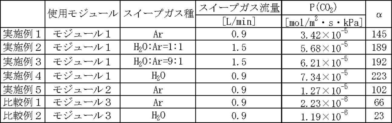
表1に示すように、実施例1~5に係る分離システムは、比較例1及び比較例2に係る分離システムよりも、CO2透過速度(P(CO2))とCO2/H2分離係数(α)が飛躍的に向上していることが分かる。
また、実施例1~4に係る分離システムは、実施例5に係る分離システムに比べ、CO2透過速度(P(CO2))とCO2/H2分離係数(α)が向上していることが分かる。
10 分離システム群
11 分離システム
12 圧力容器
14 分離モジュール
16 積層体
18 原料ガス供給口(ガスの供給口)
20 スイープガス供給口(スイープガスの供給口)
22 原料ガス排出口(ガスの排出口)
24 スイープガス排出口(スイープガスの排出口)
26 積層体
28 原料ガス(ガス)
30 スイープガス
32 中心管(管体)
32A 貫通孔
34 原料ガス供給源
36 スイープガス供給源
38A 促進輸送膜
40C 導入口
40 被覆部材
44 二酸化炭素ガス(ガス成分)
50 供給ガス流路用部材
52 二酸化炭素ガス分離部材(分離部材)
52A 促進輸送膜
52B 多孔質支持体
54 透過ガス流路用部材
11 分離システム
12 圧力容器
14 分離モジュール
16 積層体
18 原料ガス供給口(ガスの供給口)
20 スイープガス供給口(スイープガスの供給口)
22 原料ガス排出口(ガスの排出口)
24 スイープガス排出口(スイープガスの排出口)
26 積層体
28 原料ガス(ガス)
30 スイープガス
32 中心管(管体)
32A 貫通孔
34 原料ガス供給源
36 スイープガス供給源
38A 促進輸送膜
40C 導入口
40 被覆部材
44 二酸化炭素ガス(ガス成分)
50 供給ガス流路用部材
52 二酸化炭素ガス分離部材(分離部材)
52A 促進輸送膜
52B 多孔質支持体
54 透過ガス流路用部材
2012年9月28日に出願された日本国特許出願2012-218422の開示は、その全体が参照により本明細書に取り込まれる。本明細書に記載された全ての文献、特許出願、および技術規格は、個々の文献、特許出願、および技術規格が参照により取り込まれることが具体的かつ個々に記された場合と同程度に、本明細書中に参照により取り込まれる。本発明の例示的実施形態についての以上の記載は例示および説明の目的でされたものであり、網羅的であることあるいは発明を開示されている形態そのものに限定することを意図するものではない。明らかなことではあるが、多くの改変あるいは変更が当業者には自明である。上記実施形態は発明の原理及び実用的応用を最もうまく説明し、想定される特定の用途に適するような種々の実施形態や種々の改変と共に他の当業者が発明を理解できるようにするために選択され、記載された。本発明の範囲は以下の請求項およびその均等物によって規定されることが意図されている。
Claims (13)
- 外周面に貫通孔が形成された管体と、
ガスが供給される供給ガス流路用部材と、前記供給ガス流路用部材を通過する前記ガス中のガス成分を透過して分離させる分離部材と、前記分離部材を透過した前記ガス成分が前記貫通孔に向かって流れる透過ガス流路用部材と、を積層し、前記貫通孔を覆うように前記管体に多重に巻き付けられた積層体と、
前記積層体を覆って外部への前記ガスの通過を遮断すると共に、外部から前記透過ガス流路用部材の開放された巻き終わり端部へのスイープガスの導入口が形成された被覆部材と、
を有する分離モジュール。 - 前記透過ガス流路用部材の幅方向両端部は封止され、
前記供給ガス流路用部材の幅方向両端部は前記ガスの導入口となり、前記供給ガス流路用部材の巻き終わり端部は封止されている、
請求項1に記載の分離モジュール。 - 前記透過ガス流路用部材の幅方向両端部は封止され、
前記供給ガス流路用部材の幅方向両端部は前記ガスの導入口となり、前記供給ガス流路用部材の巻き終わり端部は封止されていない、
請求項1に記載の分離モジュール。 - 前記スイープガスの導入口からは、前記透過ガス流路用部材の巻き終わり端部が露出している、
請求項1~請求項3の何れか1項に記載の分離モジュール。 - 前記スイープガスの導入口からは、前記透過ガス流路用部材の巻き終わり端部が露出していない、
請求項1~請求項3の何れか1項に記載の分離モジュール。 - 前記分離部材は、
前記供給ガス流路用部材を通過する前記ガス中のガス成分である酸性ガスと反応するキャリア及び前記キャリアを担持する水溶性高分子化合物を含有し、前記供給ガス流路用部材側に設けられた促進輸送膜と、
前記透過ガス流路用部材側に設けられ、前記促進輸送膜を支持する多孔質支持体と、
を有する、
請求項1~請求項5の何れか1項に記載の分離モジュール。 - 前記促進輸送膜は、前記キャリアと前記水溶性高分子化合物の他、炭素数3~20のアルキル基又は炭素数3~20のフッ化アルキル基と親水性基とを有する化合物及びシロキサン構造を有する化合物からなる群より選ばれる化合物、並びに平均粒子径が0.01μm~1000μmでかつ比重が0.5g/cm3~1.3g/cm3のポリマー粒子から選ばれる少なくとも一種を含む、
請求項6に記載の分離モジュール。 - 前記キャリアは、アルカリ金属塩である、
請求項6又は請求項7に記載の分離モジュール。 - 前記アルカリ金属塩が、セシウム、ルビジウム、カリウム、リチウム、及びナトリウムからなる群から選択されるアルカリ金属元素を含む化合物である、請求項8に記載の分離モジュール。
- 前記水溶性高分子化合物が、下記(A)群より選ばれた単一又は複数の架橋可能基により形成された、下記(B)群より選ばれた耐加水分解性結合を含む架橋構造を有する水溶性高分子化合物である、請求項6~請求項9の何れか1項に記載の分離モジュール。
(A)群:-OH、-NH2、-Cl、-CN、―COOH、エポキシ基
(B)群:エーテル結合、アセタール結合、-NH-CH2-C(OH)-、-O-M-O-(Mは、Ti又はZrを表す)、-NH-M-O-(Mは、Ti又はZrを表す)、ウレタン結合、-CH2-CH(OH)-、アミド結合 - 前記水溶性高分子化合物が、ポリビニルアルコールまたはポリビニルアルコール-ポリアクリル酸塩共重合体である、請求項6~請求項10の何れか1項に記載の分離モジュール。
- 請求項1~請求項11の何れか1項に記載の分離モジュールと、
前記分離モジュールを収納する筒状の収納部と、前記収納部の側端部に設けられ前記積層体の一方の側端部と対向する前記ガスの供給口と、前記収納部の外周部に設けられ前記導入口と対向する前記スイープガスの供給口と、前記収納部の側端部に設けられ前記管体から流れ出す前記ガス成分及び前記スイープガスの排出口と、前記収納部の側端部に設けられ前記積層体の他方の側端部と対向する前記ガスの排出口と、を含む容器と、
を有する分離システム。 - 請求項12に記載の分離システムを直列に配置し、
各容器のスイープガスの供給口のうち、一の供給口はスイープガス供給源に繋がれ、残りの供給口は他の容器のスイープガスを排出する排出口に繋がれている、
分離システム群。
Applications Claiming Priority (2)
| Application Number | Priority Date | Filing Date | Title |
|---|---|---|---|
| JP2012-218422 | 2012-09-28 | ||
| JP2012218422A JP2014069147A (ja) | 2012-09-28 | 2012-09-28 | 分離モジュール、分離システム及び分離システム群 |
Publications (1)
| Publication Number | Publication Date |
|---|---|
| WO2014050997A1 true WO2014050997A1 (ja) | 2014-04-03 |
Family
ID=50388392
Family Applications (1)
| Application Number | Title | Priority Date | Filing Date |
|---|---|---|---|
| PCT/JP2013/076129 Ceased WO2014050997A1 (ja) | 2012-09-28 | 2013-09-26 | 分離モジュール、分離システム及び分離システム群 |
Country Status (2)
| Country | Link |
|---|---|
| JP (1) | JP2014069147A (ja) |
| WO (1) | WO2014050997A1 (ja) |
Families Citing this family (1)
| Publication number | Priority date | Publication date | Assignee | Title |
|---|---|---|---|---|
| KR20240004912A (ko) | 2021-05-07 | 2024-01-11 | 엔테그리스, 아이엔씨. | 다단 가스 샘플링 트랩 및 유황 종 오염물의 검출 |
Citations (6)
| Publication number | Priority date | Publication date | Assignee | Title |
|---|---|---|---|---|
| JPS5351183A (en) * | 1976-10-21 | 1978-05-10 | Toshiba Corp | Assembled body of gas separatin cells |
| JPS61120603A (ja) * | 1984-11-16 | 1986-06-07 | Hitachi Ltd | 液体分離装置 |
| JPH05131122A (ja) * | 1991-11-11 | 1993-05-28 | Toray Ind Inc | スパイラル型気体透過膜エレメント |
| JPH05131123A (ja) * | 1991-11-08 | 1993-05-28 | Nitto Denko Corp | スパイラル型膜分離装置 |
| WO1993010889A1 (en) * | 1991-11-25 | 1993-06-10 | The Dow Chemical Company | Spirally wound membrane device having three channels |
| JP2009195900A (ja) * | 2008-01-24 | 2009-09-03 | Renaissance Energy Research:Kk | 二酸化炭素分離装置 |
-
2012
- 2012-09-28 JP JP2012218422A patent/JP2014069147A/ja active Pending
-
2013
- 2013-09-26 WO PCT/JP2013/076129 patent/WO2014050997A1/ja not_active Ceased
Patent Citations (6)
| Publication number | Priority date | Publication date | Assignee | Title |
|---|---|---|---|---|
| JPS5351183A (en) * | 1976-10-21 | 1978-05-10 | Toshiba Corp | Assembled body of gas separatin cells |
| JPS61120603A (ja) * | 1984-11-16 | 1986-06-07 | Hitachi Ltd | 液体分離装置 |
| JPH05131123A (ja) * | 1991-11-08 | 1993-05-28 | Nitto Denko Corp | スパイラル型膜分離装置 |
| JPH05131122A (ja) * | 1991-11-11 | 1993-05-28 | Toray Ind Inc | スパイラル型気体透過膜エレメント |
| WO1993010889A1 (en) * | 1991-11-25 | 1993-06-10 | The Dow Chemical Company | Spirally wound membrane device having three channels |
| JP2009195900A (ja) * | 2008-01-24 | 2009-09-03 | Renaissance Energy Research:Kk | 二酸化炭素分離装置 |
Also Published As
| Publication number | Publication date |
|---|---|
| JP2014069147A (ja) | 2014-04-21 |
Similar Documents
| Publication | Publication Date | Title |
|---|---|---|
| JP5490281B2 (ja) | 酸性ガス分離モジュール、及び酸性ガス分離システム | |
| JP5829227B2 (ja) | 酸性ガス分離モジュール、酸性ガス分離装置、及びテレスコープ防止板 | |
| JP5990556B2 (ja) | 酸性ガス分離用積層体および該積層体を備えた酸性ガス分離用モジュール | |
| WO2014051117A1 (ja) | 分離モジュール、分離モジュールの製造方法、管体及び巻きズレ防止部材 | |
| JP6001013B2 (ja) | 酸性ガス分離用スパイラル型モジュール | |
| EP2959957A1 (en) | Complex for acid gas separation, module for acid gas separation, and method for manufacturing module for acid gas separation | |
| JP5990225B2 (ja) | 酸性ガス分離用積層体および該積層体を備えた酸性ガス分離用モジュール | |
| JP2016026860A (ja) | 酸性ガス分離モジュール | |
| JP2014014806A (ja) | 酸性ガス分離用複合体及びその製造方法並びに酸性ガス分離モジュール | |
| JPWO2018168820A1 (ja) | ガス分離膜エレメント、ガス分離膜モジュール、及びガス分離装置 | |
| JP6145349B2 (ja) | 酸性ガス分離モジュール | |
| JP2014065034A (ja) | 酸性ガス分離層、その製造方法及びその促進輸送膜、並びに、酸性ガス分離モジュール及び酸性ガス分離システム | |
| WO2014050997A1 (ja) | 分離モジュール、分離システム及び分離システム群 | |
| JP6037965B2 (ja) | 酸性ガス分離モジュール | |
| WO2014156087A1 (ja) | 酸性ガス分離用複合体、酸性ガス分離用モジュールおよび酸性ガス分離用モジュールの製造方法 | |
| JP2015136634A (ja) | 酸性ガス分離用スパイラル型モジュールおよび製造方法 | |
| JP2015061721A (ja) | 酸性ガス分離層、酸性ガス分離層の製造方法、および、酸性ガス分離モジュール | |
| JP5972232B2 (ja) | 酸性ガス分離モジュール | |
| JP6005003B2 (ja) | 酸性ガス分離用スパイラル型モジュール | |
| JP2015020147A (ja) | 酸性ガス分離用スパイラル型モジュール | |
| JP2015029959A (ja) | 酸性ガス分離モジュール | |
| JP2016064384A (ja) | 酸性ガス分離モジュール |
Legal Events
| Date | Code | Title | Description |
|---|---|---|---|
| 121 | Ep: the epo has been informed by wipo that ep was designated in this application |
Ref document number: 13841046 Country of ref document: EP Kind code of ref document: A1 |
|
| NENP | Non-entry into the national phase |
Ref country code: DE |
|
| 122 | Ep: pct application non-entry in european phase |
Ref document number: 13841046 Country of ref document: EP Kind code of ref document: A1 |