WO2014050940A1 - 発電機 - Google Patents
発電機 Download PDFInfo
- Publication number
- WO2014050940A1 WO2014050940A1 PCT/JP2013/076001 JP2013076001W WO2014050940A1 WO 2014050940 A1 WO2014050940 A1 WO 2014050940A1 JP 2013076001 W JP2013076001 W JP 2013076001W WO 2014050940 A1 WO2014050940 A1 WO 2014050940A1
- Authority
- WO
- WIPO (PCT)
- Prior art keywords
- stator
- bracket
- cylindrical portion
- cooling fan
- fixed
- Prior art date
- Legal status (The legal status is an assumption and is not a legal conclusion. Google has not performed a legal analysis and makes no representation as to the accuracy of the status listed.)
- Ceased
Links
Images


Classifications
-
- H—ELECTRICITY
- H02—GENERATION; CONVERSION OR DISTRIBUTION OF ELECTRIC POWER
- H02K—DYNAMO-ELECTRIC MACHINES
- H02K5/00—Casings; Enclosures; Supports
- H02K5/04—Casings or enclosures characterised by the shape, form or construction thereof
-
- F—MECHANICAL ENGINEERING; LIGHTING; HEATING; WEAPONS; BLASTING
- F16—ENGINEERING ELEMENTS AND UNITS; GENERAL MEASURES FOR PRODUCING AND MAINTAINING EFFECTIVE FUNCTIONING OF MACHINES OR INSTALLATIONS; THERMAL INSULATION IN GENERAL
- F16M—FRAMES, CASINGS OR BEDS OF ENGINES, MACHINES OR APPARATUS, NOT SPECIFIC TO ENGINES, MACHINES OR APPARATUS PROVIDED FOR ELSEWHERE; STANDS; SUPPORTS
- F16M1/00—Frames or casings of engines, machines or apparatus; Frames serving as machinery beds
- F16M1/04—Frames or casings of engines, machines or apparatus; Frames serving as machinery beds for rotary engines or similar machines
-
- H—ELECTRICITY
- H02—GENERATION; CONVERSION OR DISTRIBUTION OF ELECTRIC POWER
- H02K—DYNAMO-ELECTRIC MACHINES
- H02K1/00—Details of the magnetic circuit
- H02K1/06—Details of the magnetic circuit characterised by the shape, form or construction
- H02K1/12—Stationary parts of the magnetic circuit
- H02K1/18—Means for mounting or fastening magnetic stationary parts on to, or to, the stator structures
- H02K1/185—Means for mounting or fastening magnetic stationary parts on to, or to, the stator structures to outer stators
-
- H—ELECTRICITY
- H02—GENERATION; CONVERSION OR DISTRIBUTION OF ELECTRIC POWER
- H02K—DYNAMO-ELECTRIC MACHINES
- H02K5/00—Casings; Enclosures; Supports
- H02K5/04—Casings or enclosures characterised by the shape, form or construction thereof
- H02K5/15—Mounting arrangements for bearing-shields or end plates
-
- H—ELECTRICITY
- H02—GENERATION; CONVERSION OR DISTRIBUTION OF ELECTRIC POWER
- H02K—DYNAMO-ELECTRIC MACHINES
- H02K5/00—Casings; Enclosures; Supports
- H02K5/04—Casings or enclosures characterised by the shape, form or construction thereof
- H02K5/16—Means for supporting bearings, e.g. insulating supports or means for fitting bearings in the bearing-shields
- H02K5/173—Means for supporting bearings, e.g. insulating supports or means for fitting bearings in the bearing-shields using bearings with rolling contact, e.g. ball bearings
- H02K5/1732—Means for supporting bearings, e.g. insulating supports or means for fitting bearings in the bearing-shields using bearings with rolling contact, e.g. ball bearings radially supporting the rotary shaft at both ends of the rotor
-
- H—ELECTRICITY
- H02—GENERATION; CONVERSION OR DISTRIBUTION OF ELECTRIC POWER
- H02K—DYNAMO-ELECTRIC MACHINES
- H02K5/00—Casings; Enclosures; Supports
- H02K5/04—Casings or enclosures characterised by the shape, form or construction thereof
- H02K5/20—Casings or enclosures characterised by the shape, form or construction thereof with channels or ducts for flow of cooling medium
- H02K5/207—Casings or enclosures characterised by the shape, form or construction thereof with channels or ducts for flow of cooling medium with openings in the casing specially adapted for ambient air
-
- H—ELECTRICITY
- H02—GENERATION; CONVERSION OR DISTRIBUTION OF ELECTRIC POWER
- H02K—DYNAMO-ELECTRIC MACHINES
- H02K9/00—Arrangements for cooling or ventilating
- H02K9/02—Arrangements for cooling or ventilating by ambient air flowing through the machine
- H02K9/04—Arrangements for cooling or ventilating by ambient air flowing through the machine having means for generating a flow of cooling medium
- H02K9/06—Arrangements for cooling or ventilating by ambient air flowing through the machine having means for generating a flow of cooling medium with fans or impellers driven by the machine shaft
-
- H—ELECTRICITY
- H02—GENERATION; CONVERSION OR DISTRIBUTION OF ELECTRIC POWER
- H02K—DYNAMO-ELECTRIC MACHINES
- H02K5/00—Casings; Enclosures; Supports
- H02K5/24—Casings; Enclosures; Supports specially adapted for suppression or reduction of noise or vibrations
Definitions
- a stator is fixed to a housing having a first bracket having a bearing portion that pivotally supports one end portion of a rotating shaft, and a second bracket that covers a cooling fan that rotates together with the rotating shaft, and is surrounded by the stator.
- the present invention relates to a generator in which a rotor is fixed to the rotating shaft.
- a generator in which a housing is configured such that a stator core is sandwiched between first and second brackets is already known from Patent Document 1 and the like.
- the stator is sandwiched between the first and second brackets while the outer periphery of the stator faces the outside, and the first and second brackets are fastened with a plurality of long through bolts.
- the cooling efficiency of the stator is excellent because the cooling air sucked by the cooling fan only flows through the stator core.
- the present invention has been made in view of such circumstances.
- a long through bolt is unnecessary, and cooling air flows along the outer periphery of the stator. It aims at providing the generator which aimed at the cooling efficiency improvement of the stator.
- a stator in a housing having a first bracket having a bearing that pivotally supports one end of a rotating shaft, and a second bracket that covers a cooling fan that rotates together with the rotating shaft.
- the stator In the generator in which the rotor surrounded by the stator is fixed to the rotating shaft, the stator is fixed to the first bracket, and the cooling air sucked by the cooling fan is supplied to the outer periphery of the stator.
- a first feature is that a cylindrical portion surrounding the stator is integrally provided so as to be circulated therebetween, and a second bracket is coupled to the cylindrical portion.
- the present invention has a second feature that a plurality of circumferential positions on the outer periphery of the stator are press-fitted into the cylindrical portion.
- the present invention provides a ring plate facing the cooling fan side end of the cooling fan or the cylindrical portion and facing the cooling fan side end of the stator.
- a third feature is that the partition plate is fixed.
- a second bracket fastened to a drive source including a drive shaft connected coaxially to the rotation shaft, and one end of the rotation shaft To engage both ends of a plurality of knock pins for positioning the rotational shaft and the drive shaft together before fastening the first bracket in a state of being rotatably supported by the bearing portion.
- the fourth feature is that the positioning holes are provided in the first and second brackets, respectively.
- cooling is performed between the inner periphery of the cylindrical portion provided in the first bracket and the outer periphery of the stator fixed to the first bracket and surrounded by the cylindrical portion. Since the cooling air sucked by the fan flows, the cooling air is circulated along the outer periphery of the stator to increase the cooling efficiency of the stator, and the first and second brackets are coupled without using a long through bolt. Cost reduction.
- the stator is fixed to the first bracket by press-fitting a plurality of circumferential portions thereof into the cylindrical portion, so that the number of parts can be reduced.
- the ring plate-like partition plate fixed to the cooling fan or the cylindrical portion opposes the end portion of the stator on the cooling fan side, and therefore flows along the outer periphery of the stator.
- the end of the stator on the cooling fan side can be effectively cooled with the cooling air by changing the direction in which the cooling air has flowed to the rotating shaft side at the end of the stator on the cooling fan side.
- the second bracket fastened to the drive source and the first bracket in a state where one end portion of the rotating shaft is rotatably supported by the bearing portion.
- a plurality of dowel pins are used to position the rotating shaft and the drive shaft together, so that a concave-convex fitting portion is not required and the outer shape of the second bracket is increased as compared with the fitting positioning. Without increasing the outside diameter of the cooling fan, the cooling effect can be further improved.
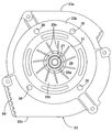
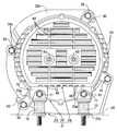
- FIG. 1 is a side view of the generator according to the first embodiment.
- FIG. 2 is a view taken in the direction of arrow 2 in FIG.
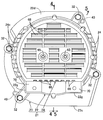
- FIG. 3 is a view taken in the direction of arrow 3 in FIG.
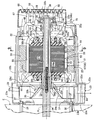
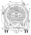
- First embodiment 4 is a cross-sectional view taken along line 4-4 of FIG.
- First embodiment 5 is a cross-sectional view taken along line 5-5 of FIG.
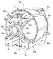
- First embodiment 6 is a perspective view of the first bracket.
- FIG. 7 is a perspective view of the second bracket.
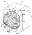
- FIG. 8 is a perspective view of the rotor and the cooling fan.
- (First embodiment) 9 is a cross-sectional view taken along line 9-9 of FIG. (First embodiment) FIG.
- FIG. 10 is a perspective view of the bobbin half.
- (First embodiment) 11 is a cross-sectional view of the rotor taken along line 11-11 in FIG.
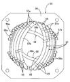
- FIG. 12 is a perspective view of the stator.
- FIG. 13 is a front view of one end of the stator as viewed from the direction along the axis of the rotating shaft.
- FIG. 14 is a view corresponding to FIG. 3 in a state in which a vibration-proof rubber is attached to the attachment portion.
- FIG. 15 is a view corresponding to FIG. 3 in a state in which a mounting leg is mounted on the mounting portion.
- FIG. 16 is a view corresponding to FIG.
- FIG. 17 shows a second embodiment of the present invention and is a sectional view corresponding to a part of FIG. (Second Embodiment)
- FIGS. 1 to 16 The first embodiment of the present invention will be described with reference to FIGS. 1 to 16.
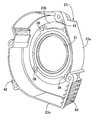
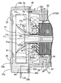
- the housing 21 of the generator is coupled to the first bracket 22 and the first bracket 22.
- a cover 24 attached to the first bracket 22 on the opposite side of the second bracket 23.
- a stator 25 is fixed to the first bracket 22 of the housing 21, and one end portion of the rotating shaft 27 is connected to the ball bearing 28 on the bearing portion 22 a of the first bracket 22.
- a rotor 26 that is rotatably supported through the stator 25 and is surrounded by the stator 25 is fixed to the rotary shaft 27, and a cooling fan 29 that rotates together with the rotary shaft 27 is covered with the second bracket 23.
- the first bracket 22 has a substantially cylindrical shape surrounding the bearing portion 22 a formed in a short cylindrical shape so as to fit the outer ring 28 a of the ball bearing 28 and the stator 25.
- the cylindrical portion 22b and one end of the cylindrical portion 22b are spaced apart in the circumferential direction of the bearing portion 22a, for example, four locations, and the other end is spaced in the circumferential direction of the one end portion of the cylindrical portion 22b.
- a retaining ring 30 for preventing axial movement of the ball bearing 28 in the bearing portion 22a is interposed.
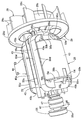
- the second bracket 23 has a cylindrical side wall portion 23a whose one end is coupled to the cylindrical portion 22b of the first bracket 22, and a radius from the other end of the side wall portion 23a.
- An inward flange 23b projecting inward in the direction is integrally formed, and a circular opening 31 is formed on the inner periphery of the inward flange 23b.
- a flat outward flange 22d is integrally provided so as to protrude outward, and on the outer periphery of the outward flange 22d.
- a coupling protrusion 22e that slightly protrudes toward the second bracket 23 so as to abut one end of the side wall 23a is formed in one piece.
- the coupling protrusion 22e of the first bracket 22 is bolts 32, 32... Arranged at a plurality of locations spaced in the circumferential direction of the cylindrical portion 22b, and the side wall portion 23a of the second bracket 23.
- the second bracket 23 is attached to a drive source having a crankshaft 34 as a drive shaft connected coaxially to the rotary shaft 27, for example, an engine body 35 of the internal combustion engine E.
- the flange 23b is provided with a plurality of, for example, four fastening holes 36, 36,... Disposed around the opening 31, and the second bracket 23 has bolts 37, which are inserted into the fastening holes 36, 36,. 37... Are fastened to the engine body 35 at 37.
- the rotary shaft 27 has a tapered hole 38 at the end on the internal combustion engine E side, and is formed in a cylindrical shape.
- the rotary shaft 27 is inserted into the second bracket 23 through the opening 31.
- a tapered portion 34a at the end of the crankshaft 34 is fitted coaxially into the tapered hole 38, and a bolt 39 inserted into the rotating shaft 27 from the cover 24 side is screwed into the crankshaft 34 and tightened.
- the rotary shaft 27 is coaxially connected to the crankshaft 34 so as not to be relatively rotatable.
- the first bracket 22 is fastened to the engine body 35 in a state where the rotor 25 is fixed to a rotating shaft 27 to which the stator 25 is fixed and one end portion is rotatably supported by the bearing portion 22a.
- the two end portions of a plurality of, for example, two knock pins 40 for positioning the rotary shaft 27 and the crankshaft 34 to be aligned with each other. are provided in the coupling protrusion 22e of the first bracket 22 and the side wall 23a of the second bracket 23, respectively.
- the rotor 26 is formed by laminating a plurality of electromagnetic steel plates, and on a rotor core 43 fixed to the rotary shaft 27, a plane passing through the central axis of the rotary shaft 27.
- Field coils 45, 45 arranged on both sides of the PL are wound around a bobbin 44.
- One end of the rotating shaft 27 is press-fitted into an inner ring 28b of the ball bearing 28, and a pair of fields is provided on the outer periphery of a slip ring support 46 fixed to the rotating shaft 27 between the ball bearing 28 and the rotor 26.
- a pair of slip rings 47, 47 electrically connected to the magnetic coils 45, 45 are provided at intervals in the axial direction of the rotary shaft 27 and are supported by the first bracket 22 as shown in FIG. 4.
- a pair of brushes 49, 49 held by the brush holder 48 are in sliding contact with the slip rings 47, 47 individually.
- the bobbin 44 is attached to the rotor core 43 such that a pair of bobbin halves 50 and 50 formed in the same shape by a synthetic resin sandwich the rotor core 43 from both sides in a direction along the axis of the rotating shaft 27. Become.
- the bobbin half 50 includes a cylindrical support portion 50 a through which the rotation shaft 27 is inserted outside the rotor core 43 along the axis of the rotation shaft 27, and the rotation shaft 27.
- a pair of ends that are connected to both sides of the inner end of the cylindrical support portion 50a so as to extend along the one plane PL passing through the central axis, and that are opposed to and contact the outer end of the rotor core 43 along the axis of the rotary shaft 27.
- the plate portions 50b, 50b, and two ends of the end plate portions 50b are connected to the longitudinal ends on the one plane PL side.
- the inner side plate portions 50c, 50c,..., The outer side plate portions 50d, 50d, ... facing the inner side plate portions 50c, 50c, ..., and the inner side plate portions 50c, 50c, ... and the inner side plate portions 50d, 50d, ... are connected. Opening grooves 51, 51 ... are formed respectively by the bottom plate portions 50e, 50e ..., and two pairs of grooves 51, 51 ... which make a pair in the direction along the one plane PL are the bobbin half 50, that is, the bobbin. 44. Further, the inner regulating plate portions 50f, 50f are provided with flow holes 52, 52... Located on both sides of the cylindrical support portion 50a, and the flow holes 52, 52 are in a direction along the axis of the rotary shaft 27. Are formed integrally with the bobbin half 50.
- coil sides 45 a and 45 a of the field coil 45 are accommodated in the grooves 51 and 51 that form a pair in the direction along the one plane PL passing through the central axis of the rotating shaft 27.
- the coil end portions 45b and 45b at both ends of the field coil 45 are restricted from moving toward the one plane PL by the inner regulating plate portion 50f so as to connect the paired coil side portions 45a and 45a. It arrange
- the coil ends 45b and 45b of the field coil 45 are formed on the bobbin 44 at the portion corresponding to the outer end of the rotor core 43, as shown in FIG.
- Separating projections 50i, 50i are provided to divide the outer side portion 45ba ... and the outer side portion 45bb ..., and the inner projections are formed on both sides of the separating projections 50i, 50i along the circumferential direction of the rotary shaft 27.
- Gaps 53 are formed between the side portions 45ba and the outer side portions 45bb, respectively.
- the end plate portion 50b of the bobbin 44 has support bases 50j and 50j that protrude from the central portion in the longitudinal direction outward in the axial direction of the rotary shaft 27 and support the coil end portions 45b and 45b.
- the air passages 54 and 54 are formed between the coil end portions 45b and the end plate portions 50b on both sides of the support bases 50j and 50j along the circumferential direction of the rotary shaft 27, and are integrated with the end plate portion 50b.
- the separation protrusions 50i are projected from the support base 50j.
- air passages 54, 54 formed between the coil end portion 45 b and the end plate portion 50 b on both sides of the support base 50 j are formed at the outer ends along the radial direction of the rotating shaft 27 and the support base 50 j and
- the inner ends of the air passages 54, 54 that open to the outside of the rotor 26 through the space between the outer restricting protrusions 50 k, 50 k and extend along the radial direction of the rotating shaft 27 are provided in the inner restricting plate portion 50 f. It is opened to the outside of the rotor 26 at the outer end along the axial direction of the rotary shaft 27 through the flow holes 52.
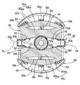
- the stator 25 includes a plurality of output coils 57, 57... And a pair of stator coils 56, which are formed by laminating a plurality of electromagnetic steel plates and provided with a plurality of slots 55.
- the exciting coils 58 and 58 are wound.
- stator 25 is fixed to the first bracket 22 so as to be surrounded by the cylindrical portion 22b of the first bracket 22, and the cooling air sucked by the cooling fan 29 is the rotor 26.
- the stator 25 can be circulated between the outer periphery of the stator 25 and the inner periphery of the cylindrical portion 22b.
- a plurality of circumferential locations, for example, four locations on the outer periphery of the stator core 56 are press-fitted into the cylindrical portion 22b.
- the inner periphery of the cylindrical portion 22b is tapered with the second bracket 23 side as the maximum diameter in order to facilitate the insertion of the stator core 56 into the cylindrical portion 22b from the second bracket 23 side.
- the press-fit portions 59 for press-fitting the outer periphery of the stator core 56 are provided at four locations spaced in the circumferential direction of the intermediate portion of the cylindrical portion 22b.
- the press-fit portions 59 have the press-fit surfaces 60 extending along the axis of the rotary shaft 27 at the tip and extend in parallel to the direction along the axis of the rotary shaft 27. It is composed of two or three ridges 61, 61 ... projecting integrally on the inner surface of 22b, and between each of the ridges 61, 61 ... between the outer circumference of the stator 25 and the inner circumference of the cylindrical portion 22b.
- the cooling air can be circulated.
- the plurality of output coils 57, 57... And the pair of exciting coils 58, 58 are separated from each other in the circumferential direction of the stator core 56 with a plurality of slots 55, 55.
- a plurality of coil side portions 57a, 57a,... 58a, 58a,... Accommodated in 55, 55 are arranged outside the both axial ends of the stator core 56.
- stator core 56 is located on the inner side of the inner periphery of the stator core 56 when viewed from the direction along the axis of the rotary shaft 27.
- a plurality of coil end portions 57b, 57b,..., 58b, 58b connecting the two slots 55, 55 by shortcutting the plurality of conductors constituting the coil end portions 57b, 57b,. .., And the coil end portions 57b, 57b,... 58b, 58b that are dispersedly arranged so as to form an opening 62 that allows the rotation shaft 27 to pass therethrough at the center. are fixed to each other by varnish impregnation.
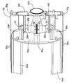
- the cooling fan 29 includes a cylindrical mounting tube portion 29 a that is fitted and fixed to the rotating shaft 27 in the second bracket 23, and the rotor 26.
- a taper tube portion 29b having a small diameter end connected to the mounting tube portion 29a so as to increase in diameter in the opposite direction, and a base end at a circumferentially spaced position on the outer periphery of the taper tube portion 29b Are formed in a ring shape so as to face the cooling fan 29 side end of the stator 25 and on the outer periphery of the plurality of blades 29c, 29c.
- a ring plate-like partition plate 29d provided in common is integrally provided, and a plurality of reinforcing ribs 29e, 29e,... Are integrally protruded from the inner periphery of the tapered cylindrical portion 29b.
- a discharge cylinder part 23c for discharging the cooling air discharged from the cooling fan 29 to the side is integrally provided at the lower part of the second bracket 23, and an outer end opening of the discharge cylinder part 23c is provided. Is provided with a louver 64 that divides the outer end opening into a plurality of sections.
- the cover 24 has a cylindrical side wall portion 24a and an end wall portion 24b that closes the outer end of the side wall portion 24a.
- the first bracket 22 is formed in a cylindrical shape and is fastened with bolts 65 and 65 to cylindrical boss portions 22f and 22f provided integrally on both sides of the bearing portion 22a in the first bracket 22. Fixed to.
- a plurality of first suction holes 66, 66... Opened downward are provided in the lower part of the side wall 24 a of the cover 24.
- a plurality of second suction holes 67 extending in the direction along the axis of the rotary shaft 27 are provided on both sides of the side wall portion 23a with a space therebetween in the vertical direction.
- 67... Are concealed in a side view, and flanges 24 c, 24 c... Projecting from the upper edges of the second suction holes 67, 67.
- the end wall portion 24b of the cover 24 is provided with a plurality of third suction holes 68, 68... By the operation of the cooling fan 29, and the first suction holes 66, 66.
- the cooling air is sucked into the housing 21 through the third suction holes 68, 68.
- the third suction holes 68 are opened downward so that water such as rainwater from the outside does not easily enter.
- one end portion of the first bracket 22, that is, the lower portion of the end portion on the cover 24 side, is a flat surface facing the cover 24 side so as to be disposed below the cover 24 when viewed from the cover 24 side.
- a pair of left and right mounting portions 22g, 22g having mounting surfaces 70, 70 are integrally provided.
- the mounting portions 22g and 22g are provided with a pair of vibration isolating rubbers 72, 72 for bolts 71, 72 for supporting the generator on the mount 69 via the vibration isolating rubbers 72, 72, for example.
- the mounting legs 73 are attached with a pair of bolts 71 and 71, and as shown in FIG.
- the state in which the stay 74 for mounting the exhaust muffler and the anti-vibration rubbers 72, 72 can be switched together by a pair of bolts 71, 71 can be switched, and the support legs of the generator can be made versatile. Can do.
- the first bracket 22 having a bearing portion 22a that pivotally supports one end of the rotating shaft 27, and the second bracket that covers the cooling fan 29 that rotates together with the rotating shaft 27.
- the stator 25 is fixed to a housing 21 having a stator 23, and the rotor 26 surrounded by the stator 25 is fixed to the rotating shaft 27.
- the stator 25 is fixed to the first bracket 22, and the A cylindrical portion 22b surrounding the stator 25 is integrally provided so that the cooling air sucked by the cooling fan 29 is circulated between the outer periphery of the stator 25, and the second bracket 23 is connected to the cylindrical portion. 22b, the cooling air is circulated along the outer periphery of the stator 25 to increase the cooling efficiency of the stator 25, and the long through-bolt
- the so as to couple the first and second brackets 22 and 23 without using the cost can be reduced.
- stator 25 since a plurality of circumferential positions on the outer periphery of the stator 25 are press-fitted into the cylindrical portion 22b, the number of parts can be reduced when the stator 25 is fixed to the first bracket 22.
- the cooling fan 29 is provided with a ring-plate-shaped partition plate 29d facing the end of the stator 25 on the cooling fan 29 side, the circulation of the cooling air that has circulated along the outer periphery of the stator 25 By changing the direction to the rotating shaft 27 side at the end of the stator 25 on the cooling fan 29 side, the end of the stator 25 on the cooling fan 29 side can be effectively cooled with cooling air.
- the second bracket 23 fastened to the engine body 35 of the internal combustion engine E including the crankshaft 34 coaxially connected to the rotary shaft 27 and one end portion of the rotary shaft 27 are rotated by the bearing portion 22a of the first bracket 22.
- both ends of a plurality of knock pins 40 for positioning the shafts of the rotary shaft 27 and the crankshaft 34 together are fitted. Since the positioning holes 41..., 42... Are provided in the first and second brackets 22 and 23, respectively, the concave and convex fitting portions are not required as compared with the case where the first and second brackets 22 and 23 are fitted and positioned. Further, it is possible to further increase the cooling effect by increasing the outer diameter of the cooling fan 29 without increasing the outer shape of the second bracket 23.
- the rotor 26 has field coils 45, 45 arranged on both sides of a plane PL passing through the central axis of the rotary shaft 27 on a bobbin 44 attached to the rotor core 43 fixed to the rotary shaft 27.
- the bobbin 44 is configured to be wound and corresponds to the outer end of the rotor core 43 in the axial direction.
- the coil end portions 45b at both ends of the field coils 45 along the axial direction of the rotary shaft 27 are provided on the bobbin 44.
- 45b are separated into an inner portion 45ba along the radial direction of the rotary shaft 27 and an outer portion 45bb..., 45b, along the circumferential direction of the rotary shaft 27.
- gaps 53 are formed between the inner side portions 45ba and the outer side portions 45b on both sides of the separation protrusions 50i, respectively, the heat dissipation area of the coil end portion 45b of the field coil 45 is formed. Increases, the coil end portions 45b and thus the field coil 45 effectively cooled, thereby improving the power generation efficiency.
- the field plate is raised from the end plate portions 50b of the bobbin 44 so as to face and abut the outer end of the rotor core 43 in the axial direction of the rotary shaft 27 from the end plate portions 50b.
- a support base 50j for supporting the coil end portion 45b of the coil 45 is provided between the coil end portion 45b and the end plate portion 50b on both sides of the support base 50j along the circumferential direction of the rotary shaft 27.
- the separation protrusion 50i is provided on the support base 50j. Therefore, the heat dissipation area of the coil end portion 45b is further increased, and the coil end portion 45b is formed. As a result, the field coil 45 can be cooled more effectively, and the power generation efficiency can be further improved.
- a plurality of slots 55, 55... are provided on the inner periphery of the stator core 56 surrounding the rotor 26 fixed to the rotary shaft 27, and the plurality of slots 55, 55.
- a plurality of coil side portions 57a, 57a,... 58a, 58a,... Housed in slots 55, 55 spaced apart from each other are arranged on the outer sides in the axial direction of the stator core 56.
- a pair of exciting coils 58, 58 connected by 58 b, 58 b are wound around the stator core 56, and at one end side along the axial direction of the stator core 56, the rotating shaft A plurality of coils that connect the two slots in a shortcut manner inwardly of the inner periphery of the stator core 56 as viewed from the direction along the axis 27
- the end portions 57b, 57b,... 58b, 58b are dispersedly arranged so as to form an opening 62 allowing the insertion of the rotating shaft 27 at the center, so that the coil end portions 57b, 57b,.
- the amount of copper can be reduced by reducing the length of the coil, and the cooling effect by the cooling air flowing through the stator core 56 can be improved, and the heat dissipation of the coil end portions 57b, 57b,.
- the area can be increased and a more excellent cooling effect can be obtained.
- a cooling fan 77 that rotates together with the rotary shaft 27 is covered with a second bracket 23, and the cooling fan 77 is covered with the second bracket 23.
- a cylindrical portion 77b and a plurality of blades 77c, 77c... Whose base end portions are connected to each other at a circumferentially spaced position on the outer periphery of the tapered cylindrical portion 77b are integrally provided.
- a ring-plate-shaped partition plate 78 facing the end of the stator 25 on the cooling fan 77 side is fixed to the end of the cylindrical portion 22b of the first bracket 22 on the cooling fan 77 side. That is, the outer peripheral portion of the partition plate 78 is fastened by a plurality of bolts 79 to the outward flange portion 22d provided integrally with the end portion of the cylindrical portion 22b on the second bracket 23 side.
- the direction of flow of the cooling air flowing along the outer periphery of the stator 25 is changed to the rotating shaft 27 side at the end of the stator 25 on the cooling fan 77 side.
- the end on the cooling fan 77 side can be effectively cooled with cooling air.
- stator 25 when the stator 25 is fixed to the first bracket 22, the stator 25 is inserted into the cylindrical portion 22b in a state where the diameter of the cylindrical portion 22b is expanded by heating the first bracket 22 to several tens of degrees C. Then, the stator 25 may be fixed to the first bracket 22 by utilizing contraction when the temperature of the first bracket 22 becomes the original temperature.
Landscapes
- Engineering & Computer Science (AREA)
- Power Engineering (AREA)
- General Engineering & Computer Science (AREA)
- Mechanical Engineering (AREA)
- Motor Or Generator Cooling System (AREA)
- Motor Or Generator Frames (AREA)
- Synchronous Machinery (AREA)
Priority Applications (3)
| Application Number | Priority Date | Filing Date | Title |
|---|---|---|---|
| EP13842975.8A EP2903140A4 (en) | 2012-09-27 | 2013-09-26 | Generator |
| US14/431,440 US9667116B2 (en) | 2012-09-27 | 2013-09-26 | Generator with brackets with positioning holes for knock pins for axial alignment of a drive shaft and a rotary shaft |
| CN201380050691.XA CN104769818B (zh) | 2012-09-27 | 2013-09-26 | 发电机 |
Applications Claiming Priority (2)
| Application Number | Priority Date | Filing Date | Title |
|---|---|---|---|
| JP2012-214189 | 2012-09-27 | ||
| JP2012214189A JP6016230B2 (ja) | 2012-09-27 | 2012-09-27 | 発電機 |
Publications (1)
| Publication Number | Publication Date |
|---|---|
| WO2014050940A1 true WO2014050940A1 (ja) | 2014-04-03 |
Family
ID=50388335
Family Applications (1)
| Application Number | Title | Priority Date | Filing Date |
|---|---|---|---|
| PCT/JP2013/076001 Ceased WO2014050940A1 (ja) | 2012-09-27 | 2013-09-26 | 発電機 |
Country Status (5)
| Country | Link |
|---|---|
| US (1) | US9667116B2 (enExample) |
| EP (1) | EP2903140A4 (enExample) |
| JP (1) | JP6016230B2 (enExample) |
| CN (1) | CN104769818B (enExample) |
| WO (1) | WO2014050940A1 (enExample) |
Cited By (3)
| Publication number | Priority date | Publication date | Assignee | Title |
|---|---|---|---|---|
| CN104104187A (zh) * | 2014-08-06 | 2014-10-15 | 中山市天虹电机制造有限公司 | 一种工业缝纫机的电机 |
| EP3059049A1 (en) * | 2015-02-17 | 2016-08-24 | X'Pole Precision Tools, Inc. | Electric handheld sanding tool providing improved cooling efficiency |
| US20160308418A1 (en) * | 2015-04-14 | 2016-10-20 | Illinois Tool Works Inc. | One-piece generator housing |
Families Citing this family (13)
| Publication number | Priority date | Publication date | Assignee | Title |
|---|---|---|---|---|
| FR3018013B1 (fr) * | 2014-02-26 | 2018-01-12 | Valeo Equipements Electriques Moteur | Ensemble electronique pour machine electrique tournante pour vehicule automobile |
| JP6787677B2 (ja) * | 2016-03-15 | 2020-11-18 | 本田技研工業株式会社 | 電動パワーユニット |
| WO2018087887A1 (ja) * | 2016-11-11 | 2018-05-17 | 三菱電機株式会社 | 回転電機の固定子およびその製造方法 |
| CN107171479A (zh) * | 2017-04-28 | 2017-09-15 | 广东威灵电机制造有限公司 | 定转子安装结构和风机系统 |
| JP6624223B2 (ja) * | 2018-03-09 | 2019-12-25 | 株式会社明電舎 | 回転電機 |
| KR102120841B1 (ko) * | 2018-11-27 | 2020-06-09 | 한국항공우주연구원 | 통합 냉각을 위한 동력 장치 및 이의 냉각 방법 |
| DE102019202048A1 (de) | 2019-02-15 | 2020-08-20 | Off-Highway Powertrain Services Germany GmbH | Zapfenkreuz und Kreuzgelenk enthaltend ein solches |
| DE102019208713A1 (de) | 2019-06-14 | 2020-12-17 | Off-Highway Powertrain Services Germany GmbH | Gelenkwelle |
| US11146144B2 (en) * | 2019-07-01 | 2021-10-12 | Nidec Motor Corporation | Motor fan and guard for directing coolant air |
| CN111600403A (zh) * | 2020-06-11 | 2020-08-28 | 浙江科胜机电有限公司 | 一种外转子永磁电机 |
| KR102888706B1 (ko) * | 2020-10-05 | 2025-11-21 | 엘지전자 주식회사 | 모터 |
| DE102020215707A1 (de) | 2020-12-11 | 2022-06-15 | Robert Bosch Gesellschaft mit beschränkter Haftung | Elektromotor und Verfahren zur Herstellung eines solchen Elektromotors |
| WO2025179075A1 (en) * | 2024-02-20 | 2025-08-28 | Ak Auto Repair, Inc. | Segmented fastener |
Citations (5)
| Publication number | Priority date | Publication date | Assignee | Title |
|---|---|---|---|---|
| JP2003061291A (ja) | 2001-08-10 | 2003-02-28 | Sawafuji Electric Co Ltd | 発動発電機用ブラケット構造 |
| JP2003204653A (ja) * | 2001-10-30 | 2003-07-18 | Denso Corp | モータ装置 |
| JP2007046767A (ja) * | 2005-05-13 | 2007-02-22 | Nsk Ltd | クリーナモータ用軸受 |
| JP2010090858A (ja) * | 2008-10-10 | 2010-04-22 | Panasonic Corp | 送風装置 |
| JP2012135139A (ja) * | 2010-12-22 | 2012-07-12 | Mitsubishi Electric Corp | 回転電機 |
Family Cites Families (14)
| Publication number | Priority date | Publication date | Assignee | Title |
|---|---|---|---|---|
| GB592904A (en) | 1945-06-05 | 1947-10-02 | English Electric Co Ltd | Improvements in and relating to dynamo electric machines |
| GB1352814A (en) | 1972-04-05 | 1974-05-15 | Ni I Exi Auto Mobilnogo Elektr | Air-ooled electrical machines |
| JPH04304144A (ja) * | 1991-03-30 | 1992-10-27 | Nippondenso Co Ltd | 車両用交流発電機 |
| US6177744B1 (en) * | 1998-03-17 | 2001-01-23 | Reliance Electric Technologies, Llc | Seal arrangement for an electric motor |
| US6124567A (en) * | 1998-12-10 | 2000-09-26 | Illinois Tool Works Inc. | Die cast housing for welding machine generator |
| US6734584B1 (en) * | 2001-06-11 | 2004-05-11 | Reliance Electric Technologies, Llc | Thermal barrier and cooling air deflector for totally enclosed motor |
| CN2836326Y (zh) * | 2003-06-17 | 2006-11-08 | 布莱克和戴克公司 | 具有双通路气流冷却装置的发电机及其方法 |
| DE102004048461A1 (de) * | 2004-10-05 | 2006-04-27 | Siemens Ag | Gehäuse für eine elektrische Maschine |
| CA2967084A1 (en) * | 2006-06-07 | 2007-12-13 | Regal Beloit America, Inc. | Totally enclosed fan cooled motor |
| US20080231126A1 (en) * | 2007-03-23 | 2008-09-25 | Rajendra Narayan Telore | Motor cooling arrangement |
| US20100176670A1 (en) * | 2009-01-12 | 2010-07-15 | Power Group International Corporation | Machine cooling scheme |
| CN201478944U (zh) * | 2009-09-09 | 2010-05-19 | 董国庆 | 双风道双风扇汽车发电机 |
| DE102009053988A1 (de) | 2009-11-23 | 2011-05-26 | Atb Technologies Gmbh | Elektrische Maschine |
| US8587165B2 (en) * | 2011-03-30 | 2013-11-19 | Dayton-Phoenix Group, Inc. | Cooled fan motor and method of operation |
-
2012
- 2012-09-27 JP JP2012214189A patent/JP6016230B2/ja not_active Expired - Fee Related
-
2013
- 2013-09-26 CN CN201380050691.XA patent/CN104769818B/zh not_active Expired - Fee Related
- 2013-09-26 US US14/431,440 patent/US9667116B2/en not_active Expired - Fee Related
- 2013-09-26 WO PCT/JP2013/076001 patent/WO2014050940A1/ja not_active Ceased
- 2013-09-26 EP EP13842975.8A patent/EP2903140A4/en not_active Withdrawn
Patent Citations (5)
| Publication number | Priority date | Publication date | Assignee | Title |
|---|---|---|---|---|
| JP2003061291A (ja) | 2001-08-10 | 2003-02-28 | Sawafuji Electric Co Ltd | 発動発電機用ブラケット構造 |
| JP2003204653A (ja) * | 2001-10-30 | 2003-07-18 | Denso Corp | モータ装置 |
| JP2007046767A (ja) * | 2005-05-13 | 2007-02-22 | Nsk Ltd | クリーナモータ用軸受 |
| JP2010090858A (ja) * | 2008-10-10 | 2010-04-22 | Panasonic Corp | 送風装置 |
| JP2012135139A (ja) * | 2010-12-22 | 2012-07-12 | Mitsubishi Electric Corp | 回転電機 |
Non-Patent Citations (1)
| Title |
|---|
| See also references of EP2903140A4 |
Cited By (5)
| Publication number | Priority date | Publication date | Assignee | Title |
|---|---|---|---|---|
| CN104104187A (zh) * | 2014-08-06 | 2014-10-15 | 中山市天虹电机制造有限公司 | 一种工业缝纫机的电机 |
| CN104104187B (zh) * | 2014-08-06 | 2017-06-23 | 中山市天虹电机制造有限公司 | 一种工业缝纫机的电机 |
| EP3059049A1 (en) * | 2015-02-17 | 2016-08-24 | X'Pole Precision Tools, Inc. | Electric handheld sanding tool providing improved cooling efficiency |
| US20160308418A1 (en) * | 2015-04-14 | 2016-10-20 | Illinois Tool Works Inc. | One-piece generator housing |
| US12119727B2 (en) * | 2015-04-14 | 2024-10-15 | Illinois Tool Works Inc. | One-piece generator housing |
Also Published As
| Publication number | Publication date |
|---|---|
| EP2903140A1 (en) | 2015-08-05 |
| JP6016230B2 (ja) | 2016-10-26 |
| CN104769818B (zh) | 2017-10-24 |
| EP2903140A4 (en) | 2016-07-20 |
| JP2014068517A (ja) | 2014-04-17 |
| US20150244235A1 (en) | 2015-08-27 |
| CN104769818A (zh) | 2015-07-08 |
| US9667116B2 (en) | 2017-05-30 |
Similar Documents
| Publication | Publication Date | Title |
|---|---|---|
| JP6016230B2 (ja) | 発電機 | |
| AU2011282138B2 (en) | Blower assembly with motor integrated into the impeller fan and blower housing constructions | |
| CN100473843C (zh) | 汽车发动机冷却风扇装置 | |
| US10594185B2 (en) | Rotor assembly and motor including same | |
| WO2018068651A1 (zh) | 一种转子结构、电机及压缩机 | |
| RU2542744C2 (ru) | Электрическая машина для гибридных или электрических транспортных средств | |
| KR20130110147A (ko) | 전기 기계 냉각 시스템 및 방법 | |
| JP2004120848A (ja) | アウタロータ型多極発電機 | |
| US20170082115A1 (en) | Electric supercharger | |
| CN106803705A (zh) | 具散热作用的马达构造 | |
| WO2014174721A1 (ja) | 誘導機 | |
| JP5858364B2 (ja) | 発電機用ロータ | |
| US20230066950A1 (en) | Motor and aircraft | |
| JP2015188279A (ja) | 発電機 | |
| JP6037108B2 (ja) | 発電機におけるステータ構造 | |
| WO2023189572A1 (ja) | 送風機及び移動体 | |
| US9083211B2 (en) | Axial gap type generator | |
| US20220299042A1 (en) | Ducted fan | |
| KR200486068Y1 (ko) | 하우징 냉각구조 | |
| US12451782B2 (en) | Motor and aircraft | |
| WO2020196117A1 (ja) | 電動コンプレッサ | |
| RU2001102971A (ru) | Двухсекционный индукторный генератор постоянного тока | |
| CN114270670A (zh) | 环形马达 | |
| KR20220100346A (ko) | 발전기 |
Legal Events
| Date | Code | Title | Description |
|---|---|---|---|
| 121 | Ep: the epo has been informed by wipo that ep was designated in this application |
Ref document number: 13842975 Country of ref document: EP Kind code of ref document: A1 |
|
| WWE | Wipo information: entry into national phase |
Ref document number: 14431440 Country of ref document: US |
|
| NENP | Non-entry into the national phase |
Ref country code: DE |
|
| REEP | Request for entry into the european phase |
Ref document number: 2013842975 Country of ref document: EP |
|
| WWE | Wipo information: entry into national phase |
Ref document number: 2013842975 Country of ref document: EP |