WO2014050512A1 - 漏洩位置特定装置、漏洩位置特定方法、漏洩位置特定プログラム、及び漏洩位置特定システム - Google Patents
漏洩位置特定装置、漏洩位置特定方法、漏洩位置特定プログラム、及び漏洩位置特定システム Download PDFInfo
- Publication number
- WO2014050512A1 WO2014050512A1 PCT/JP2013/074124 JP2013074124W WO2014050512A1 WO 2014050512 A1 WO2014050512 A1 WO 2014050512A1 JP 2013074124 W JP2013074124 W JP 2013074124W WO 2014050512 A1 WO2014050512 A1 WO 2014050512A1
- Authority
- WO
- WIPO (PCT)
- Prior art keywords
- vibration
- specifying
- measurement
- measuring device
- leakage
- Prior art date
- Legal status (The legal status is an assumption and is not a legal conclusion. Google has not performed a legal analysis and makes no representation as to the accuracy of the status listed.)
- Ceased
Links
Images





Classifications
-
- G—PHYSICS
- G01—MEASURING; TESTING
- G01M—TESTING STATIC OR DYNAMIC BALANCE OF MACHINES OR STRUCTURES; TESTING OF STRUCTURES OR APPARATUS, NOT OTHERWISE PROVIDED FOR
- G01M3/00—Investigating fluid-tightness of structures
- G01M3/02—Investigating fluid-tightness of structures by using fluid or vacuum
- G01M3/04—Investigating fluid-tightness of structures by using fluid or vacuum by detecting the presence of fluid at the leakage point
- G01M3/24—Investigating fluid-tightness of structures by using fluid or vacuum by detecting the presence of fluid at the leakage point using infrasonic, sonic or ultrasonic vibrations
- G01M3/243—Investigating fluid-tightness of structures by using fluid or vacuum by detecting the presence of fluid at the leakage point using infrasonic, sonic or ultrasonic vibrations for pipes
Definitions
- the present invention relates to a leak position specifying device, a leak position specifying method, a leak position specifying program, and a leak position specifying system.
- leakage inspection As social infrastructure, facilities such as water and sewage networks, high-pressure chemical pipelines such as gas and oil, high-speed railways, long bridges, skyscrapers, large passenger planes, and automobiles are built.
- One of the important members in these facilities is piping for passing fluids such as gas and water. Piping may fail due to deterioration or natural disasters. When a pipe breaks down and fluid leaks out, it is necessary to repair the failed part. Therefore, it is necessary to detect the leakage of the fluid in the piping and specify the fluid leakage position in the piping.
- inspections performed on fluid leakage in pipes are collectively referred to as leakage inspection.
- a general leak test is an auditory sensory test in which leak sounds are heard manually.
- manual inspection involves danger and great labor. Therefore, an apparatus for performing a leakage inspection has been proposed.
- the leak detection device described in Patent Document 1 detects a leak by converting sound detected around a pipe into an electric signal and analyzing the electric signal.
- This apparatus decomposes each electric signal obtained from the acquired sound into different frequencies using a plurality of bandpass filters. And the magnitude
- the device described in Patent Document 2 determines the presence or absence of water leakage from the ratio of the number of counts when the vibration level of the pipe due to water leakage exceeds the determination level to the number of counts less than the determination level.
- the device described in Patent Document 3 detects the presence or absence of water leakage using detection signals acquired by underwater microphones installed at both ends of the inspection section.
- the presence or absence of water leakage is determined by adding a waveform having a high correlation function of a signal detected based on the set temporary sound source position to create a composite waveform.
- Patent Document 4 uses a synchronization signal as a measurement start reference to acquire vibrations at a plurality of locations for a predetermined time to determine the presence or absence of water leakage.
- An object of the present invention is to provide a leak position specifying device that reduces energy consumed by a device used for specifying a leak position in piping, a leak position specifying method and a leak position specifying program for controlling the leak position specifying device, and a leak position It is an object of the present invention to provide a leakage position specifying system that consumes less energy by a device that is specifically used.
- the leak position specifying device specifies the leak position of fluid in the pipe using a plurality of vibration measuring devices installed in the pipe.
- the vibration measurement device includes a measurement execution unit that measures vibration at a different time from another adjacent vibration measurement device.
- specification apparatus is the 1st measurement apparatus specific means which specifies the said vibration measurement apparatus which measured the vibration which the said measurement execution means satisfy
- the leakage position specifying program provided by the present invention is a program for causing a computer to have the function of each functional component of the leakage position specifying apparatus provided by the present invention.
- a leak position specifying system includes a plurality of vibration measuring devices installed in a pipe, and a leak position specifying device for specifying a fluid leak position in the pipe using the plurality of vibration measuring devices.
- the vibration measurement device includes a measurement execution unit that measures vibration at a different time from another adjacent vibration measurement device.
- specification apparatus is a 1st measurement apparatus specific means which specifies the said vibration measurement apparatus which measured the vibration in which the said measurement execution means satisfy
- the leak position specifying method provided by the present invention is a leak position specifying method for specifying a fluid leak position in the pipe using a plurality of vibration measurement devices installed in the pipe, which is executed by a computer.
- the vibration measurement device includes a measurement execution unit that performs measurement at a time different from that of another adjacent vibration measurement device. Then, the leakage position specifying method specifies a first measuring device specifying the vibration measuring device that has measured vibration satisfying a predetermined condition among the plurality of vibration measuring devices as a first measuring device.
- FIG. 6 is a flowchart illustrating an example of a flow of a leak position specifying process performed by the leak position specifying apparatus according to the first embodiment. It is a block diagram which shows the leak position specific device which concerns on Embodiment 2 with the use environment. 10 is a flowchart illustrating an example of a flow of a leakage inspection process performed by the leakage position specifying device according to the second embodiment.
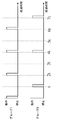
- FIG. 12 is a graph illustrating an example of a point in time when each vibration measuring device of the leakage position specifying system according to the third embodiment operates. 12 is a graph illustrating another example of a point in time when each vibration measuring device 3000 of the leakage position specifying system according to the third embodiment operates.
- each component of each device indicates a functional unit block, not a hardware unit configuration.
- Each component of each device includes a CPU, memory, a program that realizes the components shown in the figure loaded in the memory, a storage medium such as a hard disk for storing the program, and a network connection interface. It is realized by any combination of software and software. There are various modifications of the implementation method and apparatus.
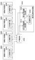
- FIG. 1 is a diagram showing a leakage position specifying device 2000 according to the present embodiment, together with its use environment.
- arrows indicate the flow of information.
- the leak position specifying device 2000 uses a plurality of vibration measuring devices 3000 installed in the pipe to specify the position where the fluid leaks in the pipe (hereinafter referred to as the leak position).
- the vibration measurement device 3000 includes a measurement execution unit 3020 that measures vibration.
- the measurement execution unit 3020 operates at a different time from the measurement execution unit 3020 of another vibration measurement device 3000 adjacent to the vibration measurement device 3000.
- the leakage position specifying device 2000 includes a first measuring device specifying unit 2010, a second measuring device specifying unit 2020, and a position specifying unit 2030.
- the first measurement device specifying unit 2010 specifies the vibration measurement device 3000 from which the measurement execution unit 3020 has measured vibrations that satisfy a predetermined condition among the plurality of vibration measurement devices 3000.
- the specified vibration measuring device 3000 is referred to as a first measuring device.
- the second measurement device specifying unit 2020 specifies any one of the two vibration measurement devices 3000 adjacent to the first measurement device 3000.
- the specified vibration measuring device 3000 is referred to as a second measuring device.
- the position specifying unit 2030 specifies the leakage position based on the installation positions of the first measurement device and the second measurement device. For example, the position specifying unit 2030 specifies that the position between the installation position of the first measurement device and the installation position of the second measurement device is a leakage position.
- FIG. 2 is a diagram conceptually illustrating a method in which the leakage position specifying device 2000 specifies a leakage position using a plurality of vibration measuring devices 3000.
- the leakage position specifying device 2000 specifies the leakage position using six vibration measuring devices 3000-1 to 3000-6 having IDs 1 to 6, respectively.
- the vibration measuring devices 3000-1 to 3000-1 are installed along the extending direction of the pipe 10.
- the leak position specifying device 2000 uses the first measuring device specifying unit 2010 to specify the vibration measuring device 3000-4 as the first measuring device.
- the second measurement device specifying unit 2020 compares the degree of leakage indicated by the vibrations measured by the vibration measurement device 3000-3 and the vibration measurement device 3000-5 adjacent to the vibration measurement device 3000-4. To do. And the 2nd measurement apparatus specific
- specification part 2020 specifies the vibration measurement apparatus 3000 with the larger degree of the leakage which the measured vibration shows among these two vibration measurement apparatuses 3000 as a 2nd measurement apparatus. In the case of this example, it is assumed that the vibration measuring device 3000-3 has a greater degree of leakage indicated by the measured vibration. In this case, as shown in FIG. 2B, the second measuring device specifying unit 2020 specifies the vibration measuring device 3000-3 as the second measuring device.
- the position specifying unit 2030 specifies that the position between the installation position of the first measurement device and the installation position of the second measurement device is a leakage position in the pipe 10.
- the installation position of the vibration measuring device 3000 is represented by the X coordinate of the place where the vibration measuring device 3000 is located, for example, when the extending direction of the pipe 10 is the X-axis direction.
- the X coordinates of the vibration measuring devices 3000-1 to 3000-1 to 6 are represented by X1 to X6, respectively. Therefore, the installation position of the vibration measurement device 3000-4 as the first measurement device is X4, and the installation position of the vibration measurement device 3000-3 as the second measurement device is X3. Therefore, the position specifying unit 2030 specifies that the hatched portion between X4 and X3 in the pipe 10 is the leakage position.
- the leak position specifying device 2000 specifies the leak position using a plurality of vibration measuring devices 3000 that operate at different times from the adjacent vibration measuring device 3000. Therefore, the leakage position specifying device 2000 consumes less energy than the vibration measuring device 3000 used for specifying the leakage position, as compared with the case where all the vibration measuring devices 3000 are operated simultaneously to specify the leakage position. Furthermore, the leakage position specifying device 2000 consumes less peak power than the vibration measuring device 3000 used for specifying the leakage position as compared with the case where all the vibration measuring devices 3000 are operated simultaneously to specify the leakage position.
- the vibration measuring device 3000 is installed along the extending direction of the same pipe.
- the vibration measuring device 3000 installed in the pipe may be installed in contact with the pipe or may be set apart from the pipe.
- the vibration measuring device 3000 is installed in the ground around the piping, the ground, or the like.
- the vibration measuring device 3000 measures the vibration of the pipe or the vibration propagated from the pipe.
- the vibration measuring device 3000 includes a vibration sensor that measures vibration of a pipe or vibration propagated from the pipe.
- the vibration sensor for example, a piezoelectric vibration sensor having a piezoelectric element can be suitably used.
- each vibration measurement device 3000 may use the same type of vibration sensor, or may use different types of vibration sensors.
- the first measuring device specifying unit 2010 specifies, as the first measuring device, the vibration measuring device 3000 from which the measurement execution unit 3020 has measured vibration satisfying a predetermined condition among the plurality of vibration measuring devices 3000.
- the predetermined condition is that the vibration indicates leakage of the pipe.
- the first measuring device specifying unit 2010 determines whether or not the vibration measured by the vibration measuring device 3000 indicates leakage by various methods.
- the first measurement device specifying unit 2010 acquires information indicating whether or not the vibration measured by each vibration measurement device 3000 indicates leakage from each vibration measurement device 3000.
- the measurement execution unit 3020 of the vibration measurement device 3000 has a function of determining whether or not the vibration to be inspected indicates leakage.
- the first measuring device specifying unit 2010 sets the vibration measuring device 3000 whose determination result is leakage as the first measuring device.
- the first measurement device specifying unit 2010 may acquire the determination result only from the vibration measurement device 3000 in which the determination result by the measurement execution unit 3020 indicates that there is leakage.
- specification part 2010 makes the vibration measuring device 3000 which acquired the said determination result a 1st measuring device.
- the leakage position specifying device 2000 and the vibration measuring device 3000 are connected to be communicable.
- the connection method between the leakage position specifying device 2000 and the vibration measuring device 3000 may be wired connection, wireless connection, or a connection method in which wired connection and wireless connection are mixed.
- the leakage position specifying device 2000 has a leakage determination unit that acquires information indicating vibration measured by the vibration measuring device 3000 and determines whether the vibration indicated by the acquired information indicates leakage. Also good.
- specification part 2010 acquires the information which specifies the vibration measuring device 3000 from which the measured vibration shows a leakage from this leak determination part.
- the first measurement device specifying unit 2010 causes the measured vibration to leak from the external device 4000 that determines whether the vibration measured by the vibration measurement device 3000 indicates leakage.
- Information for specifying the vibration measurement device 3000 shown, that is, information for specifying the first measurement device may be acquired.
- the external device 4000 is a server that is communicably connected to each vibration measuring device 3000, for example.
- each of the leakage position specifying device 2000 and each vibration measuring device 3000 is connected to be able to communicate with the external device 4000.
- the connection method between the leakage position specifying device 2000 and the external device 4000, and the vibration measuring device 3000 and the external device 4000 are both wired connection and wireless connection. A connection method may be used.
- the second measurement device specifying unit 2020 specifies, as the second measurement device, the vibration measurement device 3000 having a greater degree of leakage indicated by the measured vibration among the two vibration measurement devices 3000 adjacent to the first measurement device. .
- the second measuring device specifying unit 2020 needs to determine which vibration measuring device 3000 is adjacent to the first measuring device. There are various methods for the second measuring device specifying unit 2020 to grasp the two vibration measuring devices 3000 adjacent to the first measuring device. For example, an ID may be given to each vibration measuring device 3000 so that the second measuring device specifying unit 2020 can specify the arrangement of the vibration measuring device 3000 based on the ID of the vibration measuring device 3000. In this case, the second measuring device specifying unit 2020 grasps the vibration measuring device 3000 adjacent to the first measuring device based on the ID of the first measuring device.
- the ID for identifying the vibration measuring device 3000 is a number, and the vibration measuring device 3000 is arranged in the order of the number indicated by the ID.
- the position specifying unit 2030 acquires the ID of the first measuring device from the first measuring device specifying unit 2010.
- the first measuring device specifying unit 2010 specifies the ID of the first measuring device will be described later.
- the second measurement device specifying unit 2020 uses two vibration measurement devices 3000 whose ID is 1 smaller than the ID of the first measurement device and vibration measurement device 3000 whose ID is 1 larger than the ID of the first measurement device.
- the vibration measuring device 3000 adjacent to the measuring device is determined. For example, in the case of FIG.
- each vibration measurement device 3000 is assigned IDs 1 to 6.
- the first measurement device specifying unit 2010 specifies the vibration measurement device 3000-4 having an ID of 4 as the first measurement device. Therefore, the second measurement device specifying unit 2020 includes the vibration measurement device 3000-3 whose ID is 3 and the vibration measurement device 3000-5 whose ID is 5 adjacent to the first measurement device. To find out.
- the second measurement device specifying unit 2020 uses the installation position information indicating the combination of “ID of the vibration measurement device 3000 and the installation position of the vibration measurement device 3000” to set the installation position of each vibration measurement device 3000. May be determined.
- the second measuring device specifying unit 2020 acquires the ID of the first measuring device from the first measuring device specifying unit 2010.
- specification part 2020 reads installation position information by using ID of a 1st measuring device as a key, and calculates the installation position of a 1st measuring device.
- the second measurement device specifying unit 2020 reads the installation position information using each of the two installation positions adjacent to the installation position of the first measurement device as a key.
- the second measurement device specifying unit 2020 determines the vibration measurement device 3000 installed at each of the two installation positions adjacent to the installation position of the first measurement device.
- the installation position information may be included in the leak position specifying device 2000, or may be included in an external device that is communicably connected to the leak position specifying device 2000.
- This external device may be the same as the external device 4000 shown in FIG. 3 or may be an external device different from the external device 4000.
- the first measuring device specifying unit 2010 specifies the ID of the first measuring device. For example, when the first measurement device specifying unit 2010 acquires information from each vibration measurement device 3000, the ID of each vibration measurement device 3000 is acquired together with the information. For example, when the first measurement device specifying unit 2010 acquires information for specifying the first measurement device from the external device 4000, the first measurement device specifying unit 2010 uses the external device 4000 as information for specifying the first measurement device. To obtain the ID of the first measuring device.
- FIG. 4 is a flowchart showing an example of a flow of processing (hereinafter referred to as leakage position specifying processing) in which the leakage position specifying device 2000 of the present embodiment specifies a leakage position.
- step S102 the first measuring device specifying unit 2010 determines whether or not the vibration measured by any of the vibration measuring devices 3000 indicates leakage. When the vibration measured by any of the vibration measurement devices 3000 indicates leakage, the leakage position specifying process proceeds to step S104. If none of the vibrations measured by each vibration measuring device 3000 indicates leakage, the leakage position specifying process returns to step S102 again.
- step S104 the first measurement device specifying unit 2010 specifies the vibration measurement device 3000 in which the measured vibration indicates leakage as the first measurement device.
- step S ⁇ b> 106 the second measurement device specifying unit 2020 selects the vibration measurement device 3000 having a greater degree of leakage indicated by the measured vibration from the two vibration measurement devices 3000 adjacent to the first measurement device. As specified.
- step S108 the position specifying unit 2030 specifies that the gap between the installation position of the first measurement device and the installation position of the second measurement device is a leakage position in the pipe.
- the leakage position specifying device 2000 specifies the leakage position in the pipe using the plurality of vibration measuring devices 3000 that operate at different times from the adjacent vibration measuring device 3000. . Specifically, the leakage position specifying device 2000 specifies the vibration measuring device 3000 as the first measuring device when the vibration measured by any one of the vibration measuring devices 3000 satisfies a predetermined condition. Furthermore, one of the two vibration measurement devices 3000 adjacent to the first measurement device is specified as the second measurement device. Then, the leakage position specifying device 2000 specifies that the leakage position in the pipe is between the installation position of the first measurement device and the installation position of the second measurement device.
- the vibration measuring device 3000 operates at a time different from the other adjacent vibration measuring devices 3000. Therefore, the leakage position specifying device 2000 can reduce the energy consumed by the vibration measuring device 3000 used for specifying the leakage position, as compared to the case where all the vibration measuring devices 3000 are operated simultaneously to specify the leakage position. Furthermore, the leak position specifying device 2000 can reduce the peak power consumed by the vibration measuring device 3000 used for specifying the leak position as compared to the case where the leak position is specified by operating all the vibration measurement devices 3000 simultaneously. it can.
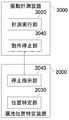
- FIG. 5 is a diagram showing the leakage position specifying device 2000 according to the present embodiment, together with its use environment.
- those having functional blocks with the same reference numerals in FIG. 1 have the same functions as the functional blocks in FIG. 1, and description thereof will be omitted as appropriate.
- the vibration measuring device 3000 further includes an operation stopping unit 3040 that receives an instruction from the leakage position specifying device 2000 and stops the operation of the vibration measuring device 3000.
- Leakage position identification device 2000 further includes a stop instruction unit 2040.
- the stop instruction unit 2040 is adjacent to the first measuring device before the second measuring device specifying unit 2020 specifies the second measuring device.
- An operation stop instruction is transmitted to the operation stop unit 3040 of the non-vibration measuring apparatus 3000.
- the first measuring device specifying unit 2010 specifies the first measuring device
- the first measuring device is instructed to the stop instruction unit 2040 before the second measuring device specifying unit 2020 specifies the second measuring device.
- the stop instruction unit 2040 instructs the vibration measurement device vibration measurement device 3000 not adjacent to the first measurement device to stop operation based on the information specifying the first measurement device acquired from the first measurement device specifying unit 2010. Send.
- the stop instruction unit 2040 determines the vibration measurement device 3000 that is not adjacent to the first measurement device. For example, the stop instruction unit 2040 acquires information indicating the vibration measurement device 3000 adjacent to the first measurement device from the second measurement device specifying unit 2020. In this way, the stop instruction unit 2040 determines that the vibration measurement device 3000 other than the vibration measurement device 3000 adjacent to the first measurement device is the vibration measurement device 3000 that is not adjacent to the first measurement device.
- the stop instruction unit 2040 may have a function of grasping the arrangement of the vibration measuring devices 3000 by the same method as the second measuring device specifying unit 2020 described in the first embodiment.
- the leakage position specifying device 2000 and the vibration measuring device 3000 are connected to be communicable.
- the connection method between the leakage position specifying device 2000 and the vibration measuring device 3000 may be wired connection, wireless connection, or a connection method in which wired connection and wireless connection are mixed.
- the leakage position specifying device 2000 in this embodiment will be described by taking the use environment shown in FIG. 2 in the first embodiment as an example. As in the first embodiment, it is assumed that the leakage position specifying device 2000 specifies the vibration measuring device 3000-4 as the first measuring device. In this case, before the second measurement device specifying unit 2020 specifies the second measurement device, the stop instruction unit 2040 is not adjacent to the vibration measurement device 3000-4 that is the first measurement device. An operation stop instruction is transmitted to 1, 2, and 6.
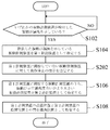
- FIG. 6 is a flowchart showing an example of the flow of the leak position specifying process performed by the leak position specifying apparatus 2000 of the present embodiment.
- the flowchart shown in FIG. 6 is the same as the flowchart shown in FIG. 4 except that step S202 is included between step S104 and step S106. Therefore, descriptions other than step S202 are omitted.
- step S202 the stop instruction unit 2040 transmits an operation stop instruction to the vibration measurement device 3000 that is not adjacent to the first measurement device. Specifically, the stop instruction unit 2040 first acquires information for specifying the first measurement device from the first measurement device specification unit 2010. Then, the stop instruction unit 2040 transmits an operation stop instruction to the vibration measurement device 3000 that is not adjacent to the first measurement device. The operation stop unit 3040 that has received the operation stop instruction stops the operation of the vibration measuring device 3000 having the operation stop unit 3040.
- the leakage position specifying device 2000 specifies the first measurement device, the vibration measurement is not adjacent to the first measurement device before specifying the second measurement device. The operation of the device 3000 is stopped. By doing so, the leakage position specifying device 2000 reduces the number of vibration measuring devices 3000 used when specifying the leakage position. Thereby, the leak position specifying device 2000 can further reduce the energy consumed by the vibration measuring device 3000 used for specifying the leak position.
- FIG. 7 is a block diagram showing a leakage position specifying system 5000 according to this embodiment.
- the internal configurations of the leakage position specifying device 2000 and the vibration measuring device 3000 are the same as those in the first embodiment or the second embodiment unless otherwise specified. Therefore, in FIG. 7, the internal configuration of the leakage position specifying device 2000 and the vibration measuring device 3000 is omitted.
- each vibration measuring device 3000 belongs to one of n groups.
- n is an integer of 2 or more.
- n ⁇ 1 vibration measurement devices 3000 belonging to another group between two adjacent vibration measurement devices 3000 belonging to the same group, there are n ⁇ 1 vibration measurement devices 3000 belonging to another group.
- “two vibration measurement devices 3000 belonging to the same group are adjacent to each other” means another vibration belonging to the same group as the two vibration measurement devices 3000 between the two vibration measurement devices 3000. It means that the measuring device 3000 is not installed.
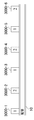
- FIG. 8 is a diagram conceptually showing a state in which a plurality of vibration measuring devices 3000 are divided into a plurality of groups.
- each vibration measuring device 3000 is installed along the extending direction of the pipe 10.
- Each vibration measuring device 3000 belongs to either group 1 or group 2.
- the numbers written inside each vibration measuring device 3000 represent the number of the group to which each vibration measuring device 3000 belongs.
- the vibration measuring device 3000-1, the vibration measuring device 3000-3, and the vibration measuring device 3000-5 belong to the group 1.
- the vibration measuring device 3000-2, the vibration measuring device 3000-4, and the vibration measuring device 3000-6 belong to the group 2.
- there are (2-1) vibration measurement devices 3000 belonging to the group 2 that is, one.
- the measurement execution unit 3020 of the vibration measurement device 3000 belonging to each group repeatedly operates at a different time or at a different period from the measurement execution unit 3020 of the vibration measurement device 3000 belonging to a different group.
- FIG. 9 is a graph conceptually showing a case where the vibration measuring device 3000 operates at a different time from the vibration measuring device 3000 belonging to another group.
- each vibration measuring device 3000 belongs to either group 1 or group 2.
- the upper graph in FIG. 9 shows a point in time when the measurement execution unit 3020 of the vibration measurement device 3000 belonging to the group 1 operates.
- the lower graph of FIG. 9 shows a point in time when the measurement execution unit 3020 of the vibration measurement device 3000 belonging to the group 2 operates.
- the measurement execution unit 3020 of each vibration measurement device 3000 in group 2 operates after the time t has elapsed since the measurement execution unit 3020 of each vibration measurement device 3000 in group 1 operates. Then, after the time t has elapsed since the measurement execution unit 3020 of each vibration measurement device 3000 in the group 2 operates, the measurement execution unit 3020 of the vibration measurement device 3000 belonging to the group 1 operates. In this way, the measurement execution unit 3020 of the vibration measurement device 3000 belonging to each group operates once until the next operation, and the measurement of the vibration measurement device 3000 belonging to each of the other n ⁇ 1 groups. The execution unit 3020 operates once at a time.
- the cycle in which the measurement execution unit 3020 of the vibration measurement device 3000 of each group operates varies. For example, after the measurement execution unit 3020 of the vibration measurement device 3000 belonging to a certain group operates once and before it operates again, the measurement execution unit 3020 of each vibration measurement device 3000 belonging to each of all other groups is once. It works one by one. This corresponds to the case of the above example using FIG.
- FIG. 10 is a graph conceptually showing a case where the vibration measuring device 3000 operates at a different period from the vibration measuring device 3000 belonging to another group.
- the graph of FIG. 10 shows an example in which the measurement execution unit 3020 of the vibration measurement device 3000 belonging to group 1 operates at a cycle of 2t, and the measurement execution unit 3020 of the vibration measurement device 3000 belonging to group 2 operates at a cycle of 3t. .
- the leak position specifying device 2000 can reduce the energy consumption of the vibration measuring device 3000 while discovering leaks in the piping at an early stage.
- the vibration measuring device 3000 may operate at a different point in time and at a different period from the vibration measuring device 3000 belonging to another group.
- the leak position specifying device 2000 of the present embodiment performs the same operation as the leak position specifying device 2000 of the first or second embodiment.
- each vibration measuring device 3000 belongs to one of n groups. Between two adjacent vibration measurement devices 3000 belonging to the same group, there are n ⁇ 1 vibration measurement devices 3000 belonging to another group.
- the measurement execution unit 3020 of the vibration measurement device 3000 belonging to each group repeatedly operates at a different time point or at a different period from the measurement execution unit 3020 of the vibration measurement device 3000 belonging to a different group. By doing in this way, when the leak in piping arises, the frequency which each vibration measuring device 3000 operates can be made low, discovering a leak early. Thereby, the leakage position specifying system 5000 can reduce the energy consumed by the vibration measuring device 3000.
- a leak position specifying device for specifying a leak position of a fluid in the pipe using a plurality of vibration measuring devices installed in the pipe,
- the vibration measuring device has a measurement execution means for measuring vibration at a different time from other adjacent vibration measuring devices
- the leakage position specifying device includes: A first measuring device specifying means for specifying, as a first measuring device, the vibration measuring device that has measured the vibration that satisfies the predetermined condition among the plurality of vibration measuring devices; A second measuring device specifying means for specifying any one of the vibration measuring devices as the second measuring device among the two vibration measuring devices adjacent to the first measuring device; Based on the installation positions of the first measurement device and the second measurement device, position specifying means for specifying a leakage position in the pipe; Leakage locating device having 2.
- the vibration measuring device further includes a stopping unit that stops an operation in response to an instruction from the leakage position specifying device, and is connected to be able to communicate with the leakage position specifying device.
- the leakage position specifying device stops operation with respect to each vibration measuring device that is not adjacent to the first measuring device specified by the first measuring device specifying means before specifying the second measuring device.
- a leakage position specifying device further comprising stop instruction means for transmitting an instruction to perform. 3.
- the second measurement position specifying means uses, as the second measurement device, the vibration measurement device having a greater degree of leakage indicated by the measured vibration among the two vibration measurement devices adjacent to the first measurement device. Identify, Leak location device. 4).
- the position specifying means specifies that the gap between the installation position of the first measurement device and the installation position of the second measurement device is a leakage position in the pipe. Leak location device. 5.
- a leakage position specifying system comprising a plurality of vibration measuring devices installed in a pipe, and a leak position specifying device for specifying a fluid leak position in the pipe using the plurality of vibration measuring devices, The vibration measuring device has a measurement execution means for measuring vibration at a different time from other adjacent vibration measuring devices,
- the leakage position specifying device includes: A first measuring device specifying means for specifying, as a first measuring device, the vibration measuring device that has measured the vibration that satisfies the predetermined condition among the plurality of vibration measuring devices; A second measuring device specifying means for specifying one of the two vibration measuring devices adjacent to the first measuring device as the second measuring device; Based on the installation positions of the first measurement device and the second measurement device, position specifying means for specifying a leakage position in the pipe; Leak
- a leak location system described in The vibration measuring device further includes a stopping unit that stops an operation in response to an instruction from the leakage position specifying device, and is connected to be able to communicate with the leakage position specifying device.
- the leakage position specifying device further includes stop instruction means for transmitting an instruction to stop the operation to each of the vibration measuring devices not adjacent to the first measuring device before specifying the second measuring device. Having a leak location system. 7). 5. Or 6.
- a leak location system described in The plurality of vibration measuring devices are divided into n groups (n is an integer of 2 or more), There are n ⁇ 1 vibration measurement devices belonging to the same group and between two adjacent vibration measurement devices belonging to another group, The leakage position specifying system in which the measurement execution unit of the vibration measurement device belonging to each group repeatedly operates at a different time point from the measurement execution unit of each vibration measurement device belonging to the other group. 8). 7).
- a leak location system described in The measurement execution unit of the vibration measurement device belonging to each group performs the measurement of each of the vibration measurement devices belonging to each of the other n ⁇ 1 groups during a period from the first operation to the next operation. Leakage location identification system in which the execution means operates once. 9. 7).
- the second measurement position specifying means uses, as the second measurement device, the vibration measurement device having a greater degree of leakage indicated by the measured vibration among the two vibration measurement devices adjacent to the first measurement device. Identify, Leak location system. 12 5. To 11. A leak location system according to any one of the above, The position specifying means specifies that the gap between the installation position of the first measurement device and the installation position of the second measurement device is a leakage position in the pipe. Leak location system. 13.
- a leakage position specifying program for causing a computer to function as a leakage position specifying device for specifying a leakage position of fluid in the pipe using a plurality of vibration measuring devices installed in the pipe,
- the vibration measuring device has a measurement execution means for measuring vibration at a different time from other adjacent vibration measuring devices,
- the leakage location specifying program is stored in the computer.
- Leakage location identification program 14 13
- the leak location program described in The vibration measuring apparatus further includes a stopping unit that stops an operation in response to an instruction from the computer, and is connected to be communicable with the computer.
- the leakage position specifying program is for the vibration measuring devices that are not adjacent to the first measuring device specified by the first measuring device specifying means before specifying the second measuring device to the computer.
- a leakage position specifying program further having a stop instruction function for transmitting an instruction to stop the operation.
- the leak location program described in The second measurement position specifying function uses, as the second measurement device, the vibration measurement device having a greater degree of leakage indicated by the measured vibration among the two vibration measurement devices adjacent to the first measurement device. Identify, Leak location program. 16. 13. To 15.
- a leakage location identification program according to any one of the above, The position specifying function specifies that a gap between an installation position of the first measurement device and an installation position of the second measurement device is a leakage position in the pipe. Leak location program. 17.
- a leak position specifying system control program for providing a leak position specifying system having a plurality of vibration measuring devices installed in a pipe and a leak position specifying apparatus to have a function of specifying a leak position in the pipe,
- the vibration measurement device has a measurement execution function for measuring vibration at a different time from other adjacent vibration measurement devices,
- a first measurement device specifying function for specifying, as a first measurement device, the vibration measurement device that has measured vibrations that satisfy a predetermined condition among the plurality of vibration measurement devices;
- a second measurement device specifying function for specifying one of the vibration measurement devices as the second measurement device among the two vibration measurement devices adjacent to the first measurement device; Based on the installation position of the first measurement device and the second measurement device, a position specifying function for specifying a leakage position in the pipe; Leakage position identification system control program.
- a leakage location specifying system control program according to claim 1, The leakage position specifying device and the vibration measuring device are connected to be communicable, The leak location system control program is The vibration measuring device further has an operation stop function for stopping the operation in response to an instruction from the leakage position specifying device, A stop instruction function for causing the leakage position specifying device to transmit an instruction to stop the operation to each of the vibration measuring devices that are not adjacent to the first measuring device before specifying the second measuring device; Leakage location identification system control program. 19. 17. Or 18.
- a leakage location specifying system control program The plurality of vibration measuring devices are divided into n groups (n is an integer of 2 or more), There are n ⁇ 1 vibration measurement devices belonging to the same group and between two adjacent vibration measurement devices belonging to another group,
- the leakage position specifying system control program is a leakage position specifying system control program for causing the vibration measuring device to have a function of repeatedly operating at different time points from the vibration measuring devices belonging to the other groups.
- 20. 19 A leakage location specifying system control program according to claim 1, A function that, when the vibration measurement device is operated once, the measurement execution unit of each vibration measurement device belonging to each of the other n ⁇ 1 groups is operated once and then the next operation is performed. Leakage position identification system control program. 21. 19.
- a leakage location specifying system control program for causing the vibration measurement device to have a function of operating the measurement execution means of the vibration measurement device belonging to a group to be different for each group. 22. 17. Or 18.
- a leakage location specifying system control program according to claim 1,
- the plurality of vibration measuring devices are divided into n groups (n is an integer of 2 or more), There are n ⁇ 1 vibration measurement devices belonging to the same group and between two adjacent vibration measurement devices belonging to another group,
- the leakage position specifying system control program is a leakage position specifying system control program for causing the vibration measuring device to have a function of repeatedly operating at a different period from each of the vibration measuring devices belonging to the other group. 23. 17. Thru 22.
- a leakage location specifying system control program uses, as the second measurement device, the vibration measurement device having a greater degree of leakage indicated by the measured vibration among the two vibration measurement devices adjacent to the first measurement device. Identify, Leak location system control program. 24. 17. Thru 23.
- a leakage location specifying system control program specifies that a gap between an installation position of the first measurement device and an installation position of the second measurement device is a leakage position in the pipe. Leak location system control program. 25.
- the vibration measuring device has a measurement execution means for measuring vibration at a different time from other adjacent vibration measuring devices
- the leak location method is A first measuring device specifying step for specifying, as the first measuring device, the vibration measuring device that has measured the vibration satisfying a predetermined condition among the plurality of vibration measuring devices;
- a method for identifying a leakage position described in The vibration measuring apparatus further includes a stopping unit that stops an operation in response to an instruction from the computer, and is connected to be communicable with the computer.
- the leakage position specifying method stops the operation of each vibration measuring device that is not adjacent to the first measuring device specified by the first measuring device specifying step before specifying the second measuring device.
- a leakage position specifying method further comprising a stop instruction step of transmitting an instruction to perform. 27. 25. Or 26.
- a method for identifying a leakage position described in In the second measurement position specifying step the vibration measurement device having a greater degree of leakage indicated by the measured vibration among the two vibration measurement devices adjacent to the first measurement device is defined as the second measurement device. Identify, Leak location method. 28. 25.
- a leakage position identification method specifies that a gap between an installation position of the first measurement device and an installation position of the second measurement device is a leakage position in the pipe. Leak location method. 29.
- a leak position specifying method in which a leak position specifying system having a plurality of vibration measuring devices installed in a pipe and a leak position specifying apparatus specifies a leak position in the pipe, A measurement execution step in which the vibration measurement device measures vibration at a different time from other adjacent vibration measurement devices; A first measuring device specifying step for specifying, as the first measuring device, the vibration measuring device that measures the vibration satisfying a predetermined condition in the measurement execution step among the plurality of vibration measuring devices; A second measuring device specifying step in which the leakage position specifying device specifies one of the vibration measuring devices as the second measuring device among the two vibration measuring devices adjacent to the first measuring device; A position specifying step in which the leak position specifying device specifies a leak position in the pipe based on an installation position of the first measuring device and the second measuring device; Leakage location identification method.
- a method for identifying a leakage position described in The leakage position specifying device and the vibration measuring device are connected to be communicable,
- the leak location method is The vibration measuring device receives an instruction from the leakage position specifying device and stops the operation, and When the leakage position specifying device specifies the first measuring device, the operation is stopped for each vibration measuring device that is not adjacent to the first measuring device before specifying the second measuring device.
- a stop instruction step for transmitting an instruction to perform, A leak location method further comprising: 31. 29. Or 30.
- a method for identifying a leakage position described in The plurality of vibration measuring devices are divided into n groups (n is an integer of 2 or more), There are n ⁇ 1 vibration measurement devices belonging to the same group and between two adjacent vibration measurement devices belonging to another group,
- the leakage position specifying method further includes a step in which the vibration measuring device repeatedly operates at a time different from each vibration measuring device belonging to the other group.
- a method for identifying a leakage position described in The measurement execution step of each of the vibration measurement devices includes the measurement execution step of each of the vibration measurement devices belonging to each of the other n ⁇ 1 groups from one operation to the next operation.
- a leak location method that works once at a time. 33. 31.
- a method for identifying a leakage position described in The plurality of vibration measuring devices are divided into n groups (n is an integer of 2 or more), There are n ⁇ 1 vibration measurement devices belonging to the same group and between two adjacent vibration measurement devices belonging to another group, The leakage position specifying method further includes a step in which the vibration measuring device repeatedly operates at a different period from each vibration measuring device belonging to the other group. 35. 29. Thru 34.
- a leakage position identification method in the second measurement position specifying step, the vibration measurement device having a greater degree of leakage indicated by the measured vibration among the two vibration measurement devices adjacent to the first measurement device is defined as the second measurement device. Identify, Leak location method. 36. 29. Thru 35.
- the position specifying step specifies that a gap between an installation position of the first measurement device and an installation position of the second measurement device is a leakage position in the pipe. Leak location method.
Landscapes
- Physics & Mathematics (AREA)
- General Physics & Mathematics (AREA)
- Examining Or Testing Airtightness (AREA)
Description
本発明は、漏洩位置特定装置、漏洩位置特定方法、漏洩位置特定プログラム、及び漏洩位置特定システムに関する。
社会基盤として、上下水道網や、ガスや石油などの高圧化学パイプライン、高速鉄道、長大橋、超高層建築、大型旅客機、自動車などの設備が建造されている。これらの設備において重要な部材の一つに、ガスや水などの流体を通す配管がある。配管は、劣化や自然災害によって故障する場合がある。配管が故障して流体が漏れ出した場合、故障した箇所を修復する必要がある。そのため、配管における流体の漏洩の検知、及び配管における流体の漏洩位置の特定を行う必要がある。以下、配管における流体の漏洩について行う検査を総称して漏洩検査と呼ぶ。
一般的な漏洩検査は、人手により漏洩音を聴き取る聴感官能検査である。しかし、配管は地中や高所に設置されている場合が多いため、人手による検査は危険と多大な労力を伴う。そこで、漏洩検査を行う装置が提案されている。
特許文献1記載の漏洩検出装置は、配管周辺で検知した音を電気信号に変換し、その電気信号を解析することで漏洩を検出する。この装置は、取得した音から得た電気信号を、複数のバンドパスフィルタを利用して異なる周波数にそれぞれ分解する。そして、各周波数の電気信号の振幅の大きさを閾値と比較する。そして、上記複数の信号全てにおいて、電気信号の振幅の大きさが閾値を超えた場合に、漏洩であると判定する。
特許文献2記載の装置は、漏水による配管の振動レベルが判定レベルを超えたカウント回数と判定レベル未満のカウント回数の比率から、漏水の有無を判定する。
特許文献3記載の装置は、検査区間の両端に設置した水中マイクで取得した検知信号を利用して漏水の有無を検知する。この手法では、設定した仮音源位置により検出された信号の相関関数の高い波形を加算して合成波形を作成することで漏水の有無を判別する。
特許文献4記載の装置は、同期信号を計測開始基準として、複数個所で所定時間の間、振動を取得し漏水の有無を判別する。
配管における漏洩位置の特定に用いる装置のメンテナンスには多くの労力を要する。その理由の1つは、配管は地中や高所に設置される場合が多いために、漏洩位置の特定に用いる装置も地中や高所に設置される場合が多いことである。また、配管には、漏洩位置の特定に用いる装置が多数設置されることも理由の1つである。そこで本発明者は、漏洩位置の特定に用いる装置のメンテナンスを行う頻度を低くするために、漏洩位置の特定に用いる装置の消費エネルギーを少なくし、漏洩位置の特定に用いる装置の動作寿命を長くすることを検討した。
本発明の目的は、配管における漏洩位置の特定に利用する装置が消費するエネルギーを少なくする漏洩位置特定装置、その漏洩位置特定装置を制御する漏洩位置特定方法及び漏洩位置特定プログラム、及び漏洩位置の特定に利用する装置が消費するエネルギーが小さい漏洩位置特定システムを提供することである。
本発明が提供する漏洩位置特定装置は、配管に設置される複数の振動計測装置を用いて前記配管における流体の漏洩位置を特定する。前記振動計測装置は、隣接する他の振動計測装置と異なる時点で振動を計測する計測実行手段を有する。そして、当該漏洩位置特定装置は、前記複数の振動計測装置のうち、前記計測実行手段が所定の条件を満たす振動を計測した前記振動計測装置を第1計測装置として特定する第1計測装置特定手段と、前記第1計測装置と隣接している2つの前記振動計測装置のうち、いずれか一方の前記振動計測装置を第2計測装置として特定する第2計測装置特定手段と、前記第1計測装置及び前記第2計測装置の設置位置に基づいて、前記配管における漏洩位置を特定する位置特定手段とを有する。
本発明が提供する漏洩位置特定プログラムは、コンピュータに、本発明が提供する上記漏洩位置特定装置の各機能構成部の機能を持たせるプログラムである。
本発明が提供する漏洩位置特定システムは、配管に設置される複数の振動計測装置と、該複数の振動計測装置を用いて前記配管における流体の漏洩位置を特定する漏洩位置特定装置とを有する漏洩位置特定システムである。前記振動計測装置は、隣接する他の振動計測装置と異なる時点で振動を計測する計測実行手段を有する。そして、前記漏洩位置特定装置は、前記複数の振動計測装置のうち、前記計測実行手段が所定の条件を満たす振動を計測した前記振動計測装置を第1計測装置として特定する第1計測装置特定手段と、前記第1計測装置と隣接している2つの前記振動計測装置のうち、いずれか一方の前記振動計測装置を第2計測装置として特定する第2計測装置特定手段と、前記第1計測装置及び前記第2計測装置の設置位置に基づいて、前記配管における漏洩位置を特定する位置特定手段とを有する。
本発明が提供する漏洩位置特定方法は、コンピュータによって実行される、配管に設置される複数の振動計測装置を用いて前記配管における流体の漏洩位置を特定する漏洩位置特定方法である。前記振動計測装置は、隣接する他の振動計測装置と異なる時点で計測する計測実行手段を有する。そして、当該当該漏洩位置特定方法は、前記複数の振動計測装置のうち、前記計測実行手段が所定の条件を満たす振動を計測した前記振動計測装置を第1計測装置として特定する第1計測装置特定ステップと、前記第1計測装置と隣接している2つの前記振動計測装置のうち、いずれか一方の前記振動計測装置を第2計測装置として特定する第2計測装置特定ステップと、前記第1計測装置及び前記第2計測装置の設置位置とに基づいて、前記配管における漏洩位置を特定する位置特定ステップとを有する。
本発明によれば、漏洩位置の特定に利用する装置が消費するエネルギーを少なくすることができる。
上述した目的、およびその他の目的、特徴および利点は、以下に述べる好適な実施の形態、およびそれに付随する以下の図面によってさらに明らかになる。
以下、本発明の実施の形態について、図面を用いて説明する。尚、すべての図面において、同様な構成要素には同様の符号を付し、適宜説明を省略する。
なお、以下に示す説明において、各装置の各構成要素は、ハードウエア単位の構成ではなく、機能単位のブロックを示している。各装置の各構成要素は、任意のコンピュータのCPU、メモリ、メモリにロードされた本図の構成要素を実現するプログラム、そのプログラムを格納するハードディスクなどの記憶メディア、ネットワーク接続用インタフェースを中心にハードウエアとソフトウエアの任意の組合せによって実現される。そして、その実現方法、装置には様々な変形例がある。
[実施形態1]
<概要>
図1は、本実施形態における漏洩位置特定装置2000を、その使用環境と共に示す図である。図1において、矢印は情報の流れを示している。
<概要>
図1は、本実施形態における漏洩位置特定装置2000を、その使用環境と共に示す図である。図1において、矢印は情報の流れを示している。
漏洩位置特定装置2000は、配管に設置される複数の振動計測装置3000を利用して、その配管において流体が漏洩している位置(以下、漏洩位置)を特定する。
振動計測装置3000は、振動を計測する計測実行部3020を有する。計測実行部3020は、当該振動計測装置3000と隣接している他の振動計測装置3000の計測実行部3020と異なる時点で動作する。
漏洩位置特定装置2000は、第1計測装置特定部2010、第2計測装置特定部2020、及び位置特定部2030を有する。第1計測装置特定部2010は、複数の振動計測装置3000のうち、計測実行部3020が所定の条件を満たす振動を計測した振動計測装置3000を特定する。以下、この特定した振動計測装置3000を第1計測装置と表記する。
第2計測装置特定部2020は、第1計測装置と隣接する2つの振動計測装置3000のうち、いずれか一方の振動計測装置3000を特定する。以下、この特定した振動計測装置3000を第2計測装置と表記する。
位置特定部2030は、第1計測装置及び第2計測装置の設置位置に基づいて、漏洩位置を特定する。例えば位置特定部2030は、第1計測装置の設置位置と、第2計測装置の設置位置との間が、漏洩位置であると特定する。
図2は、漏洩位置特定装置2000が複数の振動計測装置3000を利用して漏洩位置を特定する方法を概念的に示す図である。図2において、漏洩位置特定装置2000は、IDがそれぞれ1~6である6つの振動計測装置3000-1~6を用いて、漏洩位置の特定を行う。振動計測装置3000-1~6は、配管10の延伸方向に沿って設置されている。
図2において、振動計測装置3000-4が計測した振動が、漏洩を示したとする。この場合、図2(a)に示すように、漏洩位置特定装置2000は、第1計測装置特定部2010により、振動計測装置3000-4を第1計測装置として特定する。
上記の場合、第2計測装置特定部2020は、振動計測装置3000-4と隣接している振動計測装置3000-3及び振動計測装置3000-5のそれぞれが計測した振動が示す漏洩の度合いを比較する。そして、第2計測装置特定部2020は、この2つの振動計測装置3000のうち、計測した振動が示す漏洩の度合いがより大きい方の振動計測装置3000を第2計測装置として特定する。本例の場合、振動計測装置3000-3の方が、計測した振動が示す漏洩の度合いが大きいとする。この場合、図2(b)に示すように、第2計測装置特定部2020は、振動計測装置3000-3を第2計測装置として特定する。
最後に、位置特定部2030は、第1計測装置の設置位置と、第2計測装置の設置位置との間が、配管10における漏洩位置であると特定する。振動計測装置3000の設置位置は、例えば配管10の延伸方向をX軸方向とした場合において、振動計測装置3000が位置する場所のX座標で表される。例えば本例の場合、図2(b)が示すように、振動計測装置3000-1~6のX座標はそれぞれX1~X6で表される。したがって、第1計測装置である振動計測装置3000-4の設置位置はX4であり、第2計測装置である振動計測装置3000-3の設置位置はX3である。したがって、位置特定部2030は、配管10において、X4とX3の間である斜線部が漏洩位置であると特定する。
以上の動作により、漏洩位置特定装置2000は、隣接する振動計測装置3000と互いに異なる時点で動作する複数の振動計測装置3000を利用して、漏洩位置の特定を行う。したがって、漏洩位置特定装置2000は、全ての振動計測装置3000を同時に動作させて漏洩位置を特定する場合と比べ、漏洩位置の特定に利用する振動計測装置3000が消費する消費エネルギーが小さい。さらに、漏洩位置特定装置2000は、全ての振動計測装置3000を同時に動作させて漏洩位置を特定する場合と比べ、漏洩位置の特定に利用する振動計測装置3000が消費するピーク電力が小さい。
以下、本実施形態の詳細を説明する。
<振動計測装置3000の詳細>
例えば振動計測装置3000は、同一の配管の延伸方向に沿って設置される。配管に設置される振動計測装置3000は、配管に接触するように設置されてもよいし、配管から離れて設定されてもよい。配管から離れて設置される場合、例えば振動計測装置3000は、配管の周りの地中や地面などに設置される。
例えば振動計測装置3000は、同一の配管の延伸方向に沿って設置される。配管に設置される振動計測装置3000は、配管に接触するように設置されてもよいし、配管から離れて設定されてもよい。配管から離れて設置される場合、例えば振動計測装置3000は、配管の周りの地中や地面などに設置される。
例えば振動計測装置3000は、配管の振動又は配管から伝播する振動を計測する。例えば振動計測装置3000は、配管の振動又は配管から伝播する振動を計測する振動センサを有する。上記振動センサは、例えば圧電素子を有する圧電振動センサを好適に用いることができる。また、各振動計測装置3000はそれぞれ、同じ種類の振動センサを用いてもよいし、異なる種類の振動センサを用いてもよい。
<第1計測装置特定部2010の詳細>
第1計測装置特定部2010は、複数の振動計測装置3000のうち、計測実行部3020が所定の条件を満たす振動を計測した振動計測装置3000を、第1計測装置として特定する。例えばこの所定の条件は、その振動が配管の漏洩を示すことである。第1計測装置特定部2010は、様々な方法で、振動計測装置3000が計測した振動が漏洩を示すか否かを判断する。例えば第1計測装置特定部2010は、各振動計測装置3000から、各振動計測装置3000が計測した振動が漏洩を示すか否かを示す情報を取得する。この場合、振動計測装置3000の計測実行部3020は、検査する振動が漏洩を示すか否かを判定する機能を有する。第1計測装置特定部2010は、判定結果が漏洩有りである振動計測装置3000を第1計測装置とする。また、第1計測装置特定部2010は、計測実行部3020による判定結果が漏洩有りを示した振動計測装置3000からのみ判定結果を取得してもよい。この場合、第1計測装置特定部2010は、上記判定結果を取得した振動計測装置3000を、第1計測装置とする。また、この場合漏洩位置特定装置2000と振動計測装置3000は、通信可能に接続されている。漏洩位置特定装置2000と振動計測装置3000の接続方法は、有線接続であっても、無線接続であっても、有線接続と無線接続が混在した接続方法であってもよい。
第1計測装置特定部2010は、複数の振動計測装置3000のうち、計測実行部3020が所定の条件を満たす振動を計測した振動計測装置3000を、第1計測装置として特定する。例えばこの所定の条件は、その振動が配管の漏洩を示すことである。第1計測装置特定部2010は、様々な方法で、振動計測装置3000が計測した振動が漏洩を示すか否かを判断する。例えば第1計測装置特定部2010は、各振動計測装置3000から、各振動計測装置3000が計測した振動が漏洩を示すか否かを示す情報を取得する。この場合、振動計測装置3000の計測実行部3020は、検査する振動が漏洩を示すか否かを判定する機能を有する。第1計測装置特定部2010は、判定結果が漏洩有りである振動計測装置3000を第1計測装置とする。また、第1計測装置特定部2010は、計測実行部3020による判定結果が漏洩有りを示した振動計測装置3000からのみ判定結果を取得してもよい。この場合、第1計測装置特定部2010は、上記判定結果を取得した振動計測装置3000を、第1計測装置とする。また、この場合漏洩位置特定装置2000と振動計測装置3000は、通信可能に接続されている。漏洩位置特定装置2000と振動計測装置3000の接続方法は、有線接続であっても、無線接続であっても、有線接続と無線接続が混在した接続方法であってもよい。
その他にも例えば、漏洩位置特定装置2000は、振動計測装置3000が計測した振動を示す情報を取得し、取得した情報が示す振動が漏洩を示すか否かを判定する漏洩判定部を有してもよい。この場合、第1計測装置特定部2010は、この漏洩判定部から、計測した振動が漏洩を示す振動計測装置3000を特定する情報を取得する。
その他にも例えば、図3に示すように、第1計測装置特定部2010は、振動計測装置3000が計測した振動が漏洩を示すか否かを判定する外部装置4000から、計測した振動が漏洩を示す振動計測装置3000を特定する情報、すなわち第1計測装置を特定する情報を取得してもよい。上記外部装置4000は、例えば各振動計測装置3000と通信可能に接続されているサーバである。この場合、漏洩位置特定装置2000及び各振動計測装置3000はそれぞれ、上記外部装置4000と通信可能に接続されている。漏洩位置特定装置2000と外部装置4000、及び振動計測装置3000と外部装置4000との間の接続方法はそれぞれ、有線接続であっても、無線接続であっても、有線接続と無線接続が混在した接続方法であってもよい。
<第2計測装置特定部2020の詳細>
例えば第2計測装置特定部2020は、第1計測装置と隣接する2つの振動計測装置3000のうち、計測した振動が示す漏洩の度合いがより大きい振動計測装置3000を、第2計測装置として特定する。
例えば第2計測装置特定部2020は、第1計測装置と隣接する2つの振動計測装置3000のうち、計測した振動が示す漏洩の度合いがより大きい振動計測装置3000を、第2計測装置として特定する。
第2計測装置特定部2020は、どの振動計測装置3000が第1計測装置に隣接しているかを割り出す必要がある。第2計測装置特定部2020が第1計測装置に隣接している2つの振動計測装置3000を把握する方法は様々である。例えば、各振動計測装置3000にIDを付与しておき、第2計測装置特定部2020が振動計測装置3000のIDに基づいて振動計測装置3000の配置を特定できるようにしてもよい。この場合、第2計測装置特定部2020は、第1計測装置のIDに基づいて、第1計測装置に隣接する振動計測装置3000を把握する。
例えば、振動計測装置3000を特定するIDが数字であり、IDが示す数字の順に振動計測装置3000が並んで配置されているとする。この場合、まず位置特定部2030は、第1計測装置特定部2010から第1計測装置のIDを取得する。ここで、第1計測装置特定部2010が第1計測装置のIDを特定する方法は後述する。そして、第2計測装置特定部2020は、IDが第1計測装置のIDより1小さい振動計測装置3000と、IDが第1計測装置のIDより1大きい振動計測装置3000の2つを、第1計測装置に隣接する振動計測装置3000であると割り出す。例えば図2の場合、各振動計測装置3000は、1~6のIDを付与されている。そして図2の場合、第1計測装置特定部2010により、IDが4である振動計測装置3000-4が第1計測装置として特定されている。そこで、第2計測装置特定部2020は、IDが3である振動計測装置3000-3、及びIDが5である振動計測装置3000-5の2つが、第1計測装置に隣接する振動計測装置3000であることを割り出す。
その他にも例えば、第2計測装置特定部2020は、「振動計測装置3000のID、その振動計測装置3000の設置位置」の組み合わせを示す設置位置情報を用いて、各振動計測装置3000の設置位置を割り出してもよい。この場合、まず第2計測装置特定部2020は、第1計測装置特定部2010から第1計測装置のIDを取得する。そして、第2計測装置特定部2020は、第1計測装置のIDをキーとして設置位置情報を読み出し、第1計測装置の設置位置を割り出す。続いて、第2計測装置特定部2020は、第1計測装置の設置位置に隣接する2つの設置位置それぞれをキーとして上記設置位置情報を読み出す。その結果として、第2計測装置特定部2020は、第1計測装置の設置位置に隣接する2つの設置位置それぞれに設置されている振動計測装置3000を割り出す。上記設置位置情報は、漏洩位置特定装置2000が有していてもよいし、漏洩位置特定装置2000と通信可能に接続されている外部装置が有していてもよい。この外部装置は、図3に示す外部装置4000と同一であってもよいし、外部装置4000とは異なる外部装置であってもよい。
第1計測装置特定部2010が第1計測装置のIDを特定する方法は様々である。例えば第1計測装置特定部2010が、各振動計測装置3000から情報を取得する場合、その情報と共に各振動計測装置3000のIDを取得する。また、例えば第1計測装置特定部2010が外部装置4000から第1計測装置を特定する情報を取得する場合、第1計測装置特定部2010は、第1計測装置を特定する情報として、外部装置4000から第1計測装置のIDを取得する。
<漏洩位置特定処理の流れ>
図4は、本実施形態の漏洩位置特定装置2000が漏洩位置を特定する処理(以下、漏洩位置特定処理)の流れの一例を示すフローチャートである。
図4は、本実施形態の漏洩位置特定装置2000が漏洩位置を特定する処理(以下、漏洩位置特定処理)の流れの一例を示すフローチャートである。
ステップS102において、第1計測装置特定部2010は、いずれかの振動計測装置3000が計測した振動が漏洩を示しているか否かを判定する。いずれかの振動計測装置3000が計測した振動が漏洩を示している場合、漏洩位置特定処理は、ステップS104に進む。各振動計測装置3000が計測した振動がいずれも漏洩を示していない場合、漏洩位置特定処理は、再度ステップS102に戻る。
ステップS104において、第1計測装置特定部2010は、計測した振動が漏洩を示している振動計測装置3000を、第1計測装置として特定する。
ステップS106において、第2計測装置特定部2020は、第1計測装置に隣接する2つの振動計測装置3000のうち、計測した振動が示す漏洩の度合いがより大きい振動計測装置3000を、第2計測装置として特定する。
ステップS108において、位置特定部2030は、第1計測装置の設置位置と、第2計測装置の設置位置との間が配管における漏洩位置であると特定する。
<作用・効果>
以上の構成により、本実施形態によれば、漏洩位置特定装置2000は、隣接する振動計測装置3000と互いに異なる時点で動作する複数の振動計測装置3000を利用して配管における漏洩位置の特定を行う。具体的には、漏洩位置特定装置2000は、いずれかの振動計測装置3000において計測した振動が所定の条件を満たす場合に、その振動計測装置を3000を第1計測装置として特定する。さらに、第1計測装置に隣接する2つの振動計測装置3000のいずれかを第2計測装置として特定する。そして、漏洩位置特定装置2000は、配管における漏洩位置が、第1計測装置の設置位置と、第2計測装置の設置位置との間であると特定する。
以上の構成により、本実施形態によれば、漏洩位置特定装置2000は、隣接する振動計測装置3000と互いに異なる時点で動作する複数の振動計測装置3000を利用して配管における漏洩位置の特定を行う。具体的には、漏洩位置特定装置2000は、いずれかの振動計測装置3000において計測した振動が所定の条件を満たす場合に、その振動計測装置を3000を第1計測装置として特定する。さらに、第1計測装置に隣接する2つの振動計測装置3000のいずれかを第2計測装置として特定する。そして、漏洩位置特定装置2000は、配管における漏洩位置が、第1計測装置の設置位置と、第2計測装置の設置位置との間であると特定する。
振動計測装置3000は、隣接する他の振動計測装置3000と互いに異なる時点で動作する。そのため漏洩位置特定装置2000は、全ての振動計測装置3000を同時に動作させて漏洩位置を特定する場合と比べ、漏洩位置の特定に利用する振動計測装置3000が消費するエネルギーを少なくすることができる。さらに、漏洩位置特定装置2000は、全ての振動計測装置3000を同時に動作させて漏洩位置を特定する場合と比べ、漏洩位置の特定に利用する振動計測装置3000が消費するピーク電力を小さくすることができる。
[実施形態2]
<概要>
図5は、本実施形態における漏洩位置特定装置2000を、その使用環境と共に示す図である。図5の機能ブロックのうち、図1に同符号の機能ブロックがあるものは、図1の機能ブロックと同様の機能を有するとし、適宜説明を省略する。
<概要>
図5は、本実施形態における漏洩位置特定装置2000を、その使用環境と共に示す図である。図5の機能ブロックのうち、図1に同符号の機能ブロックがあるものは、図1の機能ブロックと同様の機能を有するとし、適宜説明を省略する。
振動計測装置3000は、漏洩位置特定装置2000からの指示を受け、振動計測装置3000の動作を停止する動作停止部3040をさらに有する。
漏洩位置特定装置2000は、停止指示部2040をさらに有する。停止指示部2040は、第1計測装置特定部2010が第1計測装置を特定した際、第2計測装置特定部2020が第2計測装置の特定を行う前に、第1計測装置に隣接していない振動計測装置3000の動作停止部3040に対して、動作停止の指示を送信する。
例えば第1計測装置特定部2010は、第1計測装置を特定した際、第2計測装置特定部2020が第2計測装置の特定を行う前に、停止指示部2040に対して、第1計測装置を特定する情報を送信する。停止指示部2040は、第1計測装置特定部2010から取得した第1計測装置を特定する情報に基づいて、第1計測装置に隣接しない振動計測装置振動計測装置3000に対して、動作停止の指示を送信する。
停止指示部2040が、第1計測装置に隣接していない振動計測装置3000を割り出す方法は様々である。例えば停止指示部2040は、第2計測装置特定部2020から、第1計測装置に隣接する振動計測装置3000を示す情報を取得する。こうすることで、停止指示部2040は、第1計測装置に隣接する振動計測装置3000以外の振動計測装置3000が第1計測装置に隣接しない振動計測装置3000であると割り出す。
その他にも例えば、停止指示部2040は、実施形態1で説明した第2計測装置特定部2020と同様の方法で、各振動計測装置3000の配置を把握する機能を有していてもよい。
漏洩位置特定装置2000と振動計測装置3000は、通信可能に接続されている。漏洩位置特定装置2000と振動計測装置3000の接続方法は、有線接続であっても、無線接続であっても、有線接続と無線接続が混在した接続方法であってもよい。
実施形態1で図2を用いて示した使用環境を例にして、本実施形態における漏洩位置特定装置2000の動作を説明する。実施形態1と同様に、漏洩位置特定装置2000は、振動計測装置3000-4を第1計測装置として特定したとする。この場合、停止指示部2040は、第2計測装置特定部2020が第2計測装置の特定を行う前に、第1計測装置である振動計測装置3000-4に隣接していない振動計測装置3000-1、2、及び6に対して、動作停止の指示を送信する。
<動作の流れ>
図6は、本実施形態の漏洩位置特定装置2000が行う漏洩位置特定処理の流れの一例を示すフローチャートである。図6が示すフローチャートは、ステップS104とステップS106の間にステップS202を有する点を除き、図4が示すフローチャートと同じである。したがって、ステップS202以外の説明は省略する。
図6は、本実施形態の漏洩位置特定装置2000が行う漏洩位置特定処理の流れの一例を示すフローチャートである。図6が示すフローチャートは、ステップS104とステップS106の間にステップS202を有する点を除き、図4が示すフローチャートと同じである。したがって、ステップS202以外の説明は省略する。
ステップS202において、停止指示部2040は、第1計測装置に隣接しない振動計測装置3000に対し、動作停止指示を送信する。具体的には、まず停止指示部2040は、第1計測装置を特定する情報を第1計測装置特定部2010から取得する。そして、停止指示部2040は、第1計測装置に隣接しない振動計測装置3000に対して、動作停止指示を送信する。動作停止指示を受信した動作停止部3040は、自身を有する振動計測装置3000の動作を停止させる。
<作用・効果>
以上の構成により、本実施形態によれば、漏洩位置特定装置2000は、第1計測装置を特定した際、第2計測装置の特定を行う前に、第1計測装置に隣接していない振動計測装置3000の動作を停止させる。こうすることで、漏洩位置特定装置2000は、漏洩位置を特定する際に利用する振動計測装置3000の数を少なくする。これにより、漏洩位置特定装置2000は、漏洩位置の特定に利用する振動計測装置3000が消費するエネルギーをさらに少なくすることができる。
以上の構成により、本実施形態によれば、漏洩位置特定装置2000は、第1計測装置を特定した際、第2計測装置の特定を行う前に、第1計測装置に隣接していない振動計測装置3000の動作を停止させる。こうすることで、漏洩位置特定装置2000は、漏洩位置を特定する際に利用する振動計測装置3000の数を少なくする。これにより、漏洩位置特定装置2000は、漏洩位置の特定に利用する振動計測装置3000が消費するエネルギーをさらに少なくすることができる。
[実施形態3]
<概要>
図7は、本実施形態に係る漏洩位置特定システム5000を示すブロック図である。ここで、漏洩位置特定装置2000及び振動計測装置3000の内部構成は、特に説明しない限り、実施形態1又は実施形態2の場合と同じである。そのため、図7において、漏洩位置特定装置2000と振動計測装置3000の内部構成は省略する。
<概要>
図7は、本実施形態に係る漏洩位置特定システム5000を示すブロック図である。ここで、漏洩位置特定装置2000及び振動計測装置3000の内部構成は、特に説明しない限り、実施形態1又は実施形態2の場合と同じである。そのため、図7において、漏洩位置特定装置2000と振動計測装置3000の内部構成は省略する。
本実施形態において、各振動計測装置3000は、n個のグループのいずれかに属する。ここで、nは2以上の整数である。同じグループに属しており、かつ隣り合う2つの振動計測装置3000の間には、他のグループに属するn-1個の振動計測装置3000が存在する。ここで、「同じグループに属している2つの振動計測装置3000が隣り合う」とは、その2つの振動計測装置3000の間に、その2つの振動計測装置3000と同一のグループに属する別の振動計測装置3000が設置されていないことを意味する。
図8は、複数の振動計測装置3000が複数のグループに分かれている様子を概念的に示す図である。図8において、各振動計測装置3000は、配管10の延伸方向に沿って設置されている。そして、各振動計測装置3000は、グループ1又はグループ2のいずれかに属している。各振動計測装置3000の内部に記載されている番号は、各振動計測装置3000が所属するグループの番号を表している。この場合、振動計測装置3000-1、振動計測装置3000-3、及び振動計測装置3000-5はグループ1に属している。一方、振動計測装置3000-2、振動計測装置3000-4、及び振動計測装置3000-6はグループ2に属している。グループ1に属する振動計測装置3000-1と振動計測装置3000-3の間には、グループ2に属する振動計測装置3000が(2-1)個、つまり1個存在する。
各グループに属する振動計測装置3000の計測実行部3020は、異なるグループに属する振動計測装置3000の計測実行部3020とは異なる時点又は異なる周期で繰り返し動作する。
図9は、振動計測装置3000が、他のグループに属する振動計測装置3000と異なる時点で動作する場合を概念的に示すグラフである。図9の例では、各振動計測装置3000はグループ1又はグループ2のいずれかのグループに属する。図9の上段のグラフは、グループ1に属する振動計測装置3000の計測実行部3020が動作する時点を示している。一方、図9の下段のグラフは、グループ2に属する振動計測装置3000の計測実行部3020が動作する時点を示している。
グラフが示すように、グループ1の各振動計測装置3000の計測実行部3020が動作してから時間 t が経過した後、グループ2の各振動計測装置3000の計測実行部3020が動作する。そして、グループ2の各振動計測装置3000の計測実行部3020が動作してから時間 t が経過した後、グループ1に属する振動計測装置3000の計測実行部3020が動作する。このように、各グループに属する振動計測装置3000の計測実行部3020が一度動作してから次に動作するまでの間に、他のn-1個のグループのそれぞれに属する振動計測装置3000の計測実行部3020が一度ずつ動作する。
各グループの振動計測装置3000の計測実行部3020が動作する周期は様々である。例えば、あるグループに属する振動計測装置3000の計測実行部3020が一度動作した後、再度動作するまでの間に、他の全てのグループのそれぞれに属する各振動計測装置3000の計測実行部3020が一度ずつ動作する。これは、図9を用いた上述の例の場合に相当する。
図10は、振動計測装置3000が、他のグループに属する振動計測装置3000と異なる周期で動作する場合を概念的に示すグラフである。図10のグラフは、グループ1に属する振動計測装置3000の計測実行部3020が周期2tで動作し、グループ2に属する振動計測装置3000の計測実行部3020が周期3tで動作する例を示している。このようにすることで、例えば配管の老朽化している部分に設置されている振動計測装置3000を含むグループにおいて振動計測装置3000の計測実行部3020が動作する頻度を高くするといったことが可能となる。こうすることで、漏洩位置特定装置2000は、配管における漏洩を早期に発見しつつ、振動計測装置3000の消費エネルギーを少なくすることができる。
振動計測装置3000は、他のグループに属する振動計測装置3000と異なる時点及び異なる周期で動作してもよい。
本実施形態の漏洩位置特定装置2000は、実施形態1又は実施形態2の漏洩位置特定装置2000と同様の動作を行う。
<作用・効果>
以上の構成により、本実施形態によれば、各振動計測装置3000は、n個のグループのいずれかに属する。同じグループに属しており、かつ隣り合う2つの振動計測装置3000の間には、他のグループに属するn-1個の振動計測装置3000が存在する。各グループに属する振動計測装置3000の計測実行部3020は、異なるグループに属する振動計測装置3000の計測実行部3020とは異なる時点又は異なる周期で繰り返し動作する。このようにすることで、配管における漏洩が起こった場合に早期に漏洩を発見しつつ、各振動計測装置3000が動作する頻度を低くすることができる。これにより、漏洩位置特定システム5000は、振動計測装置3000が消費するエネルギーを少なくすることができる。
以上の構成により、本実施形態によれば、各振動計測装置3000は、n個のグループのいずれかに属する。同じグループに属しており、かつ隣り合う2つの振動計測装置3000の間には、他のグループに属するn-1個の振動計測装置3000が存在する。各グループに属する振動計測装置3000の計測実行部3020は、異なるグループに属する振動計測装置3000の計測実行部3020とは異なる時点又は異なる周期で繰り返し動作する。このようにすることで、配管における漏洩が起こった場合に早期に漏洩を発見しつつ、各振動計測装置3000が動作する頻度を低くすることができる。これにより、漏洩位置特定システム5000は、振動計測装置3000が消費するエネルギーを少なくすることができる。
以上、図面を参照して本発明の実施形態について述べたが、これらは本発明の例示であり、上記実施形態の組み合わせ、及び上記実施形態以外の様々な構成を採用することもできる。
以下、参考形態の例を付記する。
1. 配管に設置される複数の振動計測装置を用いて前記配管における流体の漏洩位置を特定する漏洩位置特定装置であって、
前記振動計測装置は、隣接する他の振動計測装置と異なる時点で振動を計測する計測実行手段を有し、
前記漏洩位置特定装置は、
前記複数の振動計測装置のうち、前記計測実行手段が所定の条件を満たす振動を計測した前記振動計測装置を第1計測装置として特定する第1計測装置特定手段と、
前記第1計測装置と隣接している2つの前記振動計測装置のうち、いずれか一方の前記振動計測装置を第2計測装置として特定する第2計測装置特定手段と、
前記第1計測装置及び前記第2計測装置の設置位置に基づいて、前記配管における漏洩位置を特定する位置特定手段と、
を有する漏洩位置特定装置。
2. 1.に記載の漏洩位置特定装置であって、
前記振動計測装置は、前記漏洩位置特定装置の指示を受けて動作を停止する停止手段をさらに有し、前記漏洩位置特定装置と通信可能に接続されており、
前記漏洩位置特定装置は、前記第2計測装置を特定する前に、前記第1計測装置特定手段が特定した前記第1計測装置と隣接していない前記各振動計測装置に対して、動作を停止する指示を送信する停止指示手段をさらに有する漏洩位置特定装置。
3. 1.又は2.に記載の漏洩位置特定装置であって、
前記第2計測位置特定手段は、前記第1計測装置と隣接している2つの前記振動計測装置のうち、計測した振動が示す漏洩の度合いがより大きい前記振動計測装置を前記第2計測装置として特定する、
漏洩位置特定装置。
4. 1.乃至3.いずれか一項に記載の漏洩位置特定装置であって、
前記位置特定手段は、前記第1計測装置の設置位置と、前記第2計測装置の設置位置との間が、前記配管における漏洩位置であると特定する、
漏洩位置特定装置。
5. 配管に設置される複数の振動計測装置と、該複数の振動計測装置を用いて前記配管における流体の漏洩位置を特定する漏洩位置特定装置とを有する漏洩位置特定システムであって、
前記振動計測装置は、隣接する他の振動計測装置と異なる時点で振動を計測する計測実行手段を有し、
前記漏洩位置特定装置は、
前記複数の振動計測装置のうち、前記計測実行手段が所定の条件を満たす振動を計測した前記振動計測装置を第1計測装置として特定する第1計測装置特定手段と、
前記第1計測装置と隣接している2つの前記振動計測装置のいずれか一方の前記振動計測装置を第2計測装置として特定する第2計測装置特定手段と、
前記第1計測装置及び前記第2計測装置の設置位置に基づいて、前記配管における漏洩位置を特定する位置特定手段と、
を有する漏洩位置特定システム。
6. 5.に記載の漏洩位置特定システムであって、
前記振動計測装置は、前記漏洩位置特定装置の指示を受けて動作を停止する停止手段をさらに有し、前記漏洩位置特定装置と通信可能に接続されており、
前記漏洩位置特定装置は、前記第2計測装置を特定する前に、前記第1計測装置と隣接していない前記各振動計測装置に対して、動作を停止する指示を送信する停止指示手段をさらに有する漏洩位置特定システム。
7. 5.又は6.に記載の漏洩位置特定システムであって、
前記複数の振動計測装置は、n個(nは2以上の整数)のグループに分かれており、
同じグループに属しており、かつ隣り合う2つの振動計測装置の間には、他のグループに属する前記振動計測装置がn-1個あり、
前記各グループに属する振動計測装置の前記計測実行手段は、他の前記グループに属する各振動計測装置の前記計測実行手段とは異なる時点で繰り返し動作する漏洩位置特定システム。
8. 7.に記載の漏洩位置特定システムであって、
前記各グループに属する振動計測装置の前記計測実行手段は、一度動作してから次に動作するまでの間に、他のn-1個の前記グループのそれぞれに属する前記各振動計測装置の前記計測実行手段が一度ずつ動作する漏洩位置特定システム。
9. 7.に記載の漏洩位置特定システムであって、
前記グループごとに、グループに属する前記振動計測装置の前記計測実行手段が動作する周期が異なる漏洩位置特定システム。
10. 5.又は6.に記載の漏洩位置特定システムであって、
前記複数の振動計測装置は、n個(nは2以上の整数)のグループに分かれており、
同じグループに属しており、かつ隣り合う2つの振動計測装置の間には、他のグループに属する前記振動計測装置がn-1個あり、
前記各グループに属する振動計測装置の前記計測実行手段は、他の前記グループに属する各振動計測装置の前記計測実行手段とは異なる周期で繰り返し動作する漏洩位置特定システム。
11. 5.乃至10.いずれか一項に記載の漏洩位置特定システムであって、
前記第2計測位置特定手段は、前記第1計測装置と隣接している2つの前記振動計測装置のうち、計測した振動が示す漏洩の度合いがより大きい前記振動計測装置を前記第2計測装置として特定する、
漏洩位置特定システム。
12. 5.乃至11.いずれか一項に記載の漏洩位置特定システムであって、
前記位置特定手段は、前記第1計測装置の設置位置と、前記第2計測装置の設置位置との間が、前記配管における漏洩位置であると特定する、
漏洩位置特定システム。
13. コンピュータを、配管に設置される複数の振動計測装置を用いて前記配管における流体の漏洩位置を特定する漏洩位置特定装置として機能させる漏洩位置特定プログラムであって、
前記振動計測装置は、隣接する他の振動計測装置と異なる時点で振動を計測する計測実行手段を有し、
当該漏洩位置特定プログラムは、前記コンピュータに、
前記複数の振動計測装置のうち、前記計測実測手段が所定の条件を満たす振動を計測した前記振動計測装置を第1計測装置として特定する第1計測装置特定機能と、
前記第1計測装置と隣接している2つの前記振動計測装置のうち、いずれか一方の前記振動計測装置を第2計測装置として特定する第2計測装置特定機能と、
前記第1計測装置及び前記第2計測装置の設置位置に基づいて、前記配管における漏洩位置を特定する位置特定機能と、
を持たせる漏洩位置特定プログラム。
14. 13.に記載の漏洩位置特定プログラムであって、
前記振動計測装置は、前記コンピュータの指示を受けて動作を停止する停止手段をさらに有し、前記コンピュータと通信可能に接続されており、
当該漏洩位置特定プログラムは、前記コンピュータに、前記第2計測装置を特定する前に、前記第1計測装置特定手段が特定した前記第1計測装置と隣接していない前記各振動計測装置に対して、動作を停止する指示を送信する停止指示機能をさらに持たせる漏洩位置特定プログラム。
15. 13.又は14.に記載の漏洩位置特定プログラムであって、
前記第2計測位置特定機能は、前記第1計測装置と隣接している2つの前記振動計測装置のうち、計測した振動が示す漏洩の度合いがより大きい前記振動計測装置を前記第2計測装置として特定する、
漏洩位置特定プログラム。
16. 13.乃至15.いずれか一項に記載の漏洩位置特定プログラムであって、
前記位置特定機能は、前記第1計測装置の設置位置と、前記第2計測装置の設置位置との間が、前記配管における漏洩位置であると特定する、
漏洩位置特定プログラム。
17. 配管に設置される複数の振動計測装置と、漏洩位置特定装置とを有する漏洩位置特定システムに、前記配管における漏洩位置を特定する機能を持たせる漏洩位置特定システム制御プログラムであって、
前記振動計測装置に、隣接する他の振動計測装置と異なる時点で振動を計測する計測実行機能を持たせ、
前記漏洩位置特定装置に、
前記複数の振動計測装置のうち、前記計測実行手段が所定の条件を満たす振動を計測した前記振動計測装置を第1計測装置として特定する第1計測装置特定機能と、
前記第1計測装置と隣接している2つの前記振動計測装置のうち、いずれか一方の前記振動計測装置を第2計測装置として特定する第2計測装置特定機能と、
前記第1計測装置及び前記第2計測装置の設置位置とに基づいて、前記配管における漏洩位置を特定する位置特定機能と、
を持たせる漏洩位置特定システム制御プログラム。
18. 17.に記載の漏洩位置特定システム制御プログラムであって、
前記漏洩位置特定装置と前記振動計測装置は通信可能に接続されており、
当該漏洩位置特定システム制御プログラムは、
前記振動計測装置に、前記漏洩位置特定装置の指示を受けて動作を停止させる動作停止機能をさらに持たせ、
前記漏洩位置特定装置に、前記第2計測装置を特定する前に、前記第1計測装置と隣接していない前記各振動計測装置に対して、動作を停止する指示を送信させる停止指示機能をさらに持たせる漏洩位置特定システム制御プログラム。
19. 17.又は18.に記載の漏洩位置特定システム制御プログラムであって、
前記複数の振動計測装置は、n個(nは2以上の整数)のグループに分かれており、
同じグループに属しており、かつ隣り合う2つの振動計測装置の間には、他のグループに属する前記振動計測装置がn-1個あり、
当該漏洩位置特定システム制御プログラムは、前記振動計測装置に、他の前記グループに属する各振動計測装置とは異なる時点で繰り返し動作させる機能を持たせる漏洩位置特定システム制御プログラム。
20. 19.に記載の漏洩位置特定システム制御プログラムであって、
前記振動計測装置を、一度動作させた場合、他のn-1個の前記グループのそれぞれに属する前記各振動計測装置の前記計測実行手段が一度ずつ動作させてから、次の動作を行わせる機能を持たせる漏洩位置特定システム制御プログラム。
21. 19.に記載の漏洩位置特定システム制御プログラムであって、
前記振動計測装置に、前記グループごとに、グループに属する前記振動計測装置の前記計測実行手段が動作する周期が異なるように動作する機能を持たせる漏洩位置特定システム制御プログラム。
22. 17.又は18.に記載の漏洩位置特定システム制御プログラムであって、
前記複数の振動計測装置は、n個(nは2以上の整数)のグループに分かれており、
同じグループに属しており、かつ隣り合う2つの振動計測装置の間には、他のグループに属する前記振動計測装置がn-1個あり、
当該漏洩位置特定システム制御プログラムは、前記振動計測装置に、他の前記グループに属する各振動計測装置とは異なる周期で繰り返し動作する機能を持たせる漏洩位置特定システム制御プログラム。
23. 17.乃至22.いずれか一項に記載の漏洩位置特定システム制御プログラムであって、
前記第2計測位置特定機能は、前記第1計測装置と隣接している2つの前記振動計測装置のうち、計測した振動が示す漏洩の度合いがより大きい前記振動計測装置を前記第2計測装置として特定する、
漏洩位置特定システム制御プログラム。
24. 17.乃至23.いずれか一項に記載の漏洩位置特定システム制御プログラムであって、
前記位置特定機能は、前記第1計測装置の設置位置と、前記第2計測装置の設置位置との間が、前記配管における漏洩位置であると特定する、
漏洩位置特定システム制御プログラム。
25. コンピュータによって実行される、配管に設置される複数の振動計測装置を用いて前記配管における流体の漏洩位置を特定する漏洩位置特定方法であって、
前記振動計測装置は、隣接する他の振動計測装置と異なる時点で振動を計測する計測実行手段を有し、
当該漏洩位置特定方法は、
前記複数の振動計測装置のうち、前記実行計測手段が所定の条件を満たす振動を計測した前記振動計測装置を第1計測装置として特定する第1計測装置特定ステップと、
前記第1計測装置と隣接している2つの前記振動計測装置のうち、いずれか一方の前記振動計測装置を第2計測装置として特定する第2計測装置特定ステップと、
前記第1計測装置及び前記第2計測装置の設置位置に基づいて、前記配管における漏洩位置を特定する位置特定ステップと、
を有する漏洩位置特定方法。
26. 25.に記載の漏洩位置特定方法であって、
前記振動計測装置は、前記コンピュータの指示を受けて動作を停止する停止手段をさらに有し、前記コンピュータと通信可能に接続されており、
当該漏洩位置特定方法は、前記第2計測装置を特定する前に、前記第1計測装置特定ステップが特定した前記第1計測装置と隣接していない前記各振動計測装置に対して、動作を停止する指示を送信する停止指示ステップをさらに有する漏洩位置特定方法。
27. 25.又は26.に記載の漏洩位置特定方法であって、
前記第2計測位置特定ステップは、前記第1計測装置と隣接している2つの前記振動計測装置のうち、計測した振動が示す漏洩の度合いがより大きい前記振動計測装置を前記第2計測装置として特定する、
漏洩位置特定方法。
28. 25.乃至27.いずれか一項に記載の漏洩位置特定方法であって、
前記位置特定ステップは、前記第1計測装置の設置位置と、前記第2計測装置の設置位置との間が、前記配管における漏洩位置であると特定する、
漏洩位置特定方法。
29. 配管に設置される複数の振動計測装置と、漏洩位置特定装置とを有する漏洩位置特定システムが前記配管における漏洩位置を特定する漏洩位置特定方法であって、
前記振動計測装置が、隣接する他の振動計測装置と異なる時点で振動を計測する計測実行ステップと、
前記漏洩位置特定装置が、前記複数の振動計測装置のうち、前記計測実行ステップで所定の条件を満たす振動を計測した前記振動計測装置を第1計測装置として特定する第1計測装置特定ステップと、
前記漏洩位置特定装置が、前記第1計測装置と隣接している2つの前記振動計測装置のうち、いずれか一方の前記振動計測装置を第2計測装置として特定する第2計測装置特定ステップと、
前記漏洩位置特定装置が、前記第1計測装置及び前記第2計測装置の設置位置とに基づいて、前記配管における漏洩位置を特定する位置特定ステップと、
を有する漏洩位置特定方法。
30. 29.に記載の漏洩位置特定方法であって、
前記漏洩位置特定装置と前記振動計測装置とは通信可能に接続されており、
当該漏洩位置特定方法は、
前記振動計測装置が、前記漏洩位置特定装置の指示を受けて動作を停止させる動作停止ステップと、
前記漏洩位置特定装置が、前記第1計測装置を特定した際、前記第2計測装置を特定する前に、前記第1計測装置と隣接していない前記各振動計測装置に対して、動作を停止する指示を送信させる停止指示ステップと、
をさらに有する漏洩位置特定方法。
31. 29.又は30.に記載の漏洩位置特定方法であって、
前記複数の振動計測装置は、n個(nは2以上の整数)のグループに分かれており、
同じグループに属しており、かつ隣り合う2つの振動計測装置の間には、他のグループに属する前記振動計測装置がn-1個あり、
当該漏洩位置特定方法は、前記振動計測装置が、他の前記グループに属する各振動計測装置とは異なる時点で繰り返し動作するステップをさらに有する漏洩位置特定方法。
32. 31.に記載の漏洩位置特定方法であって、
前記各振動計測装置の前記計測実行ステップは、一度動作してから次に動作するまでの間に、他のn-1個の前記グループのそれぞれに属する前記各振動計測装置の前記計測実行ステップが一度ずつ動作する漏洩位置特定方法。
33. 31.に記載の漏洩位置特定方法であって、
前記グループごとに、グループに属する前記振動計測装置の前記計測実行ステップが動作する周期が異なる漏洩位置特定方法。
34. 29.又は30.に記載の漏洩位置特定方法であって、
前記複数の振動計測装置は、n個(nは2以上の整数)のグループに分かれており、
同じグループに属しており、かつ隣り合う2つの振動計測装置の間には、他のグループに属する前記振動計測装置がn-1個あり、
当該漏洩位置特定方法は、前記振動計測装置が、他の前記グループに属する各振動計測装置とは異なる周期で繰り返し動作するステップをさらに有する漏洩位置特定方法。
35. 29.乃至34.いずれか一項に記載の漏洩位置特定方法であって、
前記第2計測位置特定ステップは、前記第1計測装置と隣接している2つの前記振動計測装置のうち、計測した振動が示す漏洩の度合いがより大きい前記振動計測装置を前記第2計測装置として特定する、
漏洩位置特定方法。
36. 29.乃至35.いずれか一項に記載の漏洩位置特定方法であって、
前記位置特定ステップは、前記第1計測装置の設置位置と、前記第2計測装置の設置位置との間が、前記配管における漏洩位置であると特定する、
漏洩位置特定方法。
1. 配管に設置される複数の振動計測装置を用いて前記配管における流体の漏洩位置を特定する漏洩位置特定装置であって、
前記振動計測装置は、隣接する他の振動計測装置と異なる時点で振動を計測する計測実行手段を有し、
前記漏洩位置特定装置は、
前記複数の振動計測装置のうち、前記計測実行手段が所定の条件を満たす振動を計測した前記振動計測装置を第1計測装置として特定する第1計測装置特定手段と、
前記第1計測装置と隣接している2つの前記振動計測装置のうち、いずれか一方の前記振動計測装置を第2計測装置として特定する第2計測装置特定手段と、
前記第1計測装置及び前記第2計測装置の設置位置に基づいて、前記配管における漏洩位置を特定する位置特定手段と、
を有する漏洩位置特定装置。
2. 1.に記載の漏洩位置特定装置であって、
前記振動計測装置は、前記漏洩位置特定装置の指示を受けて動作を停止する停止手段をさらに有し、前記漏洩位置特定装置と通信可能に接続されており、
前記漏洩位置特定装置は、前記第2計測装置を特定する前に、前記第1計測装置特定手段が特定した前記第1計測装置と隣接していない前記各振動計測装置に対して、動作を停止する指示を送信する停止指示手段をさらに有する漏洩位置特定装置。
3. 1.又は2.に記載の漏洩位置特定装置であって、
前記第2計測位置特定手段は、前記第1計測装置と隣接している2つの前記振動計測装置のうち、計測した振動が示す漏洩の度合いがより大きい前記振動計測装置を前記第2計測装置として特定する、
漏洩位置特定装置。
4. 1.乃至3.いずれか一項に記載の漏洩位置特定装置であって、
前記位置特定手段は、前記第1計測装置の設置位置と、前記第2計測装置の設置位置との間が、前記配管における漏洩位置であると特定する、
漏洩位置特定装置。
5. 配管に設置される複数の振動計測装置と、該複数の振動計測装置を用いて前記配管における流体の漏洩位置を特定する漏洩位置特定装置とを有する漏洩位置特定システムであって、
前記振動計測装置は、隣接する他の振動計測装置と異なる時点で振動を計測する計測実行手段を有し、
前記漏洩位置特定装置は、
前記複数の振動計測装置のうち、前記計測実行手段が所定の条件を満たす振動を計測した前記振動計測装置を第1計測装置として特定する第1計測装置特定手段と、
前記第1計測装置と隣接している2つの前記振動計測装置のいずれか一方の前記振動計測装置を第2計測装置として特定する第2計測装置特定手段と、
前記第1計測装置及び前記第2計測装置の設置位置に基づいて、前記配管における漏洩位置を特定する位置特定手段と、
を有する漏洩位置特定システム。
6. 5.に記載の漏洩位置特定システムであって、
前記振動計測装置は、前記漏洩位置特定装置の指示を受けて動作を停止する停止手段をさらに有し、前記漏洩位置特定装置と通信可能に接続されており、
前記漏洩位置特定装置は、前記第2計測装置を特定する前に、前記第1計測装置と隣接していない前記各振動計測装置に対して、動作を停止する指示を送信する停止指示手段をさらに有する漏洩位置特定システム。
7. 5.又は6.に記載の漏洩位置特定システムであって、
前記複数の振動計測装置は、n個(nは2以上の整数)のグループに分かれており、
同じグループに属しており、かつ隣り合う2つの振動計測装置の間には、他のグループに属する前記振動計測装置がn-1個あり、
前記各グループに属する振動計測装置の前記計測実行手段は、他の前記グループに属する各振動計測装置の前記計測実行手段とは異なる時点で繰り返し動作する漏洩位置特定システム。
8. 7.に記載の漏洩位置特定システムであって、
前記各グループに属する振動計測装置の前記計測実行手段は、一度動作してから次に動作するまでの間に、他のn-1個の前記グループのそれぞれに属する前記各振動計測装置の前記計測実行手段が一度ずつ動作する漏洩位置特定システム。
9. 7.に記載の漏洩位置特定システムであって、
前記グループごとに、グループに属する前記振動計測装置の前記計測実行手段が動作する周期が異なる漏洩位置特定システム。
10. 5.又は6.に記載の漏洩位置特定システムであって、
前記複数の振動計測装置は、n個(nは2以上の整数)のグループに分かれており、
同じグループに属しており、かつ隣り合う2つの振動計測装置の間には、他のグループに属する前記振動計測装置がn-1個あり、
前記各グループに属する振動計測装置の前記計測実行手段は、他の前記グループに属する各振動計測装置の前記計測実行手段とは異なる周期で繰り返し動作する漏洩位置特定システム。
11. 5.乃至10.いずれか一項に記載の漏洩位置特定システムであって、
前記第2計測位置特定手段は、前記第1計測装置と隣接している2つの前記振動計測装置のうち、計測した振動が示す漏洩の度合いがより大きい前記振動計測装置を前記第2計測装置として特定する、
漏洩位置特定システム。
12. 5.乃至11.いずれか一項に記載の漏洩位置特定システムであって、
前記位置特定手段は、前記第1計測装置の設置位置と、前記第2計測装置の設置位置との間が、前記配管における漏洩位置であると特定する、
漏洩位置特定システム。
13. コンピュータを、配管に設置される複数の振動計測装置を用いて前記配管における流体の漏洩位置を特定する漏洩位置特定装置として機能させる漏洩位置特定プログラムであって、
前記振動計測装置は、隣接する他の振動計測装置と異なる時点で振動を計測する計測実行手段を有し、
当該漏洩位置特定プログラムは、前記コンピュータに、
前記複数の振動計測装置のうち、前記計測実測手段が所定の条件を満たす振動を計測した前記振動計測装置を第1計測装置として特定する第1計測装置特定機能と、
前記第1計測装置と隣接している2つの前記振動計測装置のうち、いずれか一方の前記振動計測装置を第2計測装置として特定する第2計測装置特定機能と、
前記第1計測装置及び前記第2計測装置の設置位置に基づいて、前記配管における漏洩位置を特定する位置特定機能と、
を持たせる漏洩位置特定プログラム。
14. 13.に記載の漏洩位置特定プログラムであって、
前記振動計測装置は、前記コンピュータの指示を受けて動作を停止する停止手段をさらに有し、前記コンピュータと通信可能に接続されており、
当該漏洩位置特定プログラムは、前記コンピュータに、前記第2計測装置を特定する前に、前記第1計測装置特定手段が特定した前記第1計測装置と隣接していない前記各振動計測装置に対して、動作を停止する指示を送信する停止指示機能をさらに持たせる漏洩位置特定プログラム。
15. 13.又は14.に記載の漏洩位置特定プログラムであって、
前記第2計測位置特定機能は、前記第1計測装置と隣接している2つの前記振動計測装置のうち、計測した振動が示す漏洩の度合いがより大きい前記振動計測装置を前記第2計測装置として特定する、
漏洩位置特定プログラム。
16. 13.乃至15.いずれか一項に記載の漏洩位置特定プログラムであって、
前記位置特定機能は、前記第1計測装置の設置位置と、前記第2計測装置の設置位置との間が、前記配管における漏洩位置であると特定する、
漏洩位置特定プログラム。
17. 配管に設置される複数の振動計測装置と、漏洩位置特定装置とを有する漏洩位置特定システムに、前記配管における漏洩位置を特定する機能を持たせる漏洩位置特定システム制御プログラムであって、
前記振動計測装置に、隣接する他の振動計測装置と異なる時点で振動を計測する計測実行機能を持たせ、
前記漏洩位置特定装置に、
前記複数の振動計測装置のうち、前記計測実行手段が所定の条件を満たす振動を計測した前記振動計測装置を第1計測装置として特定する第1計測装置特定機能と、
前記第1計測装置と隣接している2つの前記振動計測装置のうち、いずれか一方の前記振動計測装置を第2計測装置として特定する第2計測装置特定機能と、
前記第1計測装置及び前記第2計測装置の設置位置とに基づいて、前記配管における漏洩位置を特定する位置特定機能と、
を持たせる漏洩位置特定システム制御プログラム。
18. 17.に記載の漏洩位置特定システム制御プログラムであって、
前記漏洩位置特定装置と前記振動計測装置は通信可能に接続されており、
当該漏洩位置特定システム制御プログラムは、
前記振動計測装置に、前記漏洩位置特定装置の指示を受けて動作を停止させる動作停止機能をさらに持たせ、
前記漏洩位置特定装置に、前記第2計測装置を特定する前に、前記第1計測装置と隣接していない前記各振動計測装置に対して、動作を停止する指示を送信させる停止指示機能をさらに持たせる漏洩位置特定システム制御プログラム。
19. 17.又は18.に記載の漏洩位置特定システム制御プログラムであって、
前記複数の振動計測装置は、n個(nは2以上の整数)のグループに分かれており、
同じグループに属しており、かつ隣り合う2つの振動計測装置の間には、他のグループに属する前記振動計測装置がn-1個あり、
当該漏洩位置特定システム制御プログラムは、前記振動計測装置に、他の前記グループに属する各振動計測装置とは異なる時点で繰り返し動作させる機能を持たせる漏洩位置特定システム制御プログラム。
20. 19.に記載の漏洩位置特定システム制御プログラムであって、
前記振動計測装置を、一度動作させた場合、他のn-1個の前記グループのそれぞれに属する前記各振動計測装置の前記計測実行手段が一度ずつ動作させてから、次の動作を行わせる機能を持たせる漏洩位置特定システム制御プログラム。
21. 19.に記載の漏洩位置特定システム制御プログラムであって、
前記振動計測装置に、前記グループごとに、グループに属する前記振動計測装置の前記計測実行手段が動作する周期が異なるように動作する機能を持たせる漏洩位置特定システム制御プログラム。
22. 17.又は18.に記載の漏洩位置特定システム制御プログラムであって、
前記複数の振動計測装置は、n個(nは2以上の整数)のグループに分かれており、
同じグループに属しており、かつ隣り合う2つの振動計測装置の間には、他のグループに属する前記振動計測装置がn-1個あり、
当該漏洩位置特定システム制御プログラムは、前記振動計測装置に、他の前記グループに属する各振動計測装置とは異なる周期で繰り返し動作する機能を持たせる漏洩位置特定システム制御プログラム。
23. 17.乃至22.いずれか一項に記載の漏洩位置特定システム制御プログラムであって、
前記第2計測位置特定機能は、前記第1計測装置と隣接している2つの前記振動計測装置のうち、計測した振動が示す漏洩の度合いがより大きい前記振動計測装置を前記第2計測装置として特定する、
漏洩位置特定システム制御プログラム。
24. 17.乃至23.いずれか一項に記載の漏洩位置特定システム制御プログラムであって、
前記位置特定機能は、前記第1計測装置の設置位置と、前記第2計測装置の設置位置との間が、前記配管における漏洩位置であると特定する、
漏洩位置特定システム制御プログラム。
25. コンピュータによって実行される、配管に設置される複数の振動計測装置を用いて前記配管における流体の漏洩位置を特定する漏洩位置特定方法であって、
前記振動計測装置は、隣接する他の振動計測装置と異なる時点で振動を計測する計測実行手段を有し、
当該漏洩位置特定方法は、
前記複数の振動計測装置のうち、前記実行計測手段が所定の条件を満たす振動を計測した前記振動計測装置を第1計測装置として特定する第1計測装置特定ステップと、
前記第1計測装置と隣接している2つの前記振動計測装置のうち、いずれか一方の前記振動計測装置を第2計測装置として特定する第2計測装置特定ステップと、
前記第1計測装置及び前記第2計測装置の設置位置に基づいて、前記配管における漏洩位置を特定する位置特定ステップと、
を有する漏洩位置特定方法。
26. 25.に記載の漏洩位置特定方法であって、
前記振動計測装置は、前記コンピュータの指示を受けて動作を停止する停止手段をさらに有し、前記コンピュータと通信可能に接続されており、
当該漏洩位置特定方法は、前記第2計測装置を特定する前に、前記第1計測装置特定ステップが特定した前記第1計測装置と隣接していない前記各振動計測装置に対して、動作を停止する指示を送信する停止指示ステップをさらに有する漏洩位置特定方法。
27. 25.又は26.に記載の漏洩位置特定方法であって、
前記第2計測位置特定ステップは、前記第1計測装置と隣接している2つの前記振動計測装置のうち、計測した振動が示す漏洩の度合いがより大きい前記振動計測装置を前記第2計測装置として特定する、
漏洩位置特定方法。
28. 25.乃至27.いずれか一項に記載の漏洩位置特定方法であって、
前記位置特定ステップは、前記第1計測装置の設置位置と、前記第2計測装置の設置位置との間が、前記配管における漏洩位置であると特定する、
漏洩位置特定方法。
29. 配管に設置される複数の振動計測装置と、漏洩位置特定装置とを有する漏洩位置特定システムが前記配管における漏洩位置を特定する漏洩位置特定方法であって、
前記振動計測装置が、隣接する他の振動計測装置と異なる時点で振動を計測する計測実行ステップと、
前記漏洩位置特定装置が、前記複数の振動計測装置のうち、前記計測実行ステップで所定の条件を満たす振動を計測した前記振動計測装置を第1計測装置として特定する第1計測装置特定ステップと、
前記漏洩位置特定装置が、前記第1計測装置と隣接している2つの前記振動計測装置のうち、いずれか一方の前記振動計測装置を第2計測装置として特定する第2計測装置特定ステップと、
前記漏洩位置特定装置が、前記第1計測装置及び前記第2計測装置の設置位置とに基づいて、前記配管における漏洩位置を特定する位置特定ステップと、
を有する漏洩位置特定方法。
30. 29.に記載の漏洩位置特定方法であって、
前記漏洩位置特定装置と前記振動計測装置とは通信可能に接続されており、
当該漏洩位置特定方法は、
前記振動計測装置が、前記漏洩位置特定装置の指示を受けて動作を停止させる動作停止ステップと、
前記漏洩位置特定装置が、前記第1計測装置を特定した際、前記第2計測装置を特定する前に、前記第1計測装置と隣接していない前記各振動計測装置に対して、動作を停止する指示を送信させる停止指示ステップと、
をさらに有する漏洩位置特定方法。
31. 29.又は30.に記載の漏洩位置特定方法であって、
前記複数の振動計測装置は、n個(nは2以上の整数)のグループに分かれており、
同じグループに属しており、かつ隣り合う2つの振動計測装置の間には、他のグループに属する前記振動計測装置がn-1個あり、
当該漏洩位置特定方法は、前記振動計測装置が、他の前記グループに属する各振動計測装置とは異なる時点で繰り返し動作するステップをさらに有する漏洩位置特定方法。
32. 31.に記載の漏洩位置特定方法であって、
前記各振動計測装置の前記計測実行ステップは、一度動作してから次に動作するまでの間に、他のn-1個の前記グループのそれぞれに属する前記各振動計測装置の前記計測実行ステップが一度ずつ動作する漏洩位置特定方法。
33. 31.に記載の漏洩位置特定方法であって、
前記グループごとに、グループに属する前記振動計測装置の前記計測実行ステップが動作する周期が異なる漏洩位置特定方法。
34. 29.又は30.に記載の漏洩位置特定方法であって、
前記複数の振動計測装置は、n個(nは2以上の整数)のグループに分かれており、
同じグループに属しており、かつ隣り合う2つの振動計測装置の間には、他のグループに属する前記振動計測装置がn-1個あり、
当該漏洩位置特定方法は、前記振動計測装置が、他の前記グループに属する各振動計測装置とは異なる周期で繰り返し動作するステップをさらに有する漏洩位置特定方法。
35. 29.乃至34.いずれか一項に記載の漏洩位置特定方法であって、
前記第2計測位置特定ステップは、前記第1計測装置と隣接している2つの前記振動計測装置のうち、計測した振動が示す漏洩の度合いがより大きい前記振動計測装置を前記第2計測装置として特定する、
漏洩位置特定方法。
36. 29.乃至35.いずれか一項に記載の漏洩位置特定方法であって、
前記位置特定ステップは、前記第1計測装置の設置位置と、前記第2計測装置の設置位置との間が、前記配管における漏洩位置であると特定する、
漏洩位置特定方法。
この出願は、2012年9月28日に出願された日本出願特願2012-215798号を基礎とする優先権を主張し、その開示の全てをここに取り込む。
Claims (14)
- 配管に設置される複数の振動計測装置を用いて前記配管における流体の漏洩位置を特定する漏洩位置特定装置であって、
前記振動計測装置は、隣接する他の振動計測装置と異なる時点で振動を計測する計測実行手段を有し、
前記漏洩位置特定装置は、
前記複数の振動計測装置のうち、前記計測実行手段が所定の条件を満たす振動を計測した前記振動計測装置を第1計測装置として特定する第1計測装置特定手段と、
前記第1計測装置と隣接している2つの前記振動計測装置のうち、いずれか一方の前記振動計測装置を第2計測装置として特定する第2計測装置特定手段と、
前記第1計測装置及び前記第2計測装置の設置位置に基づいて、前記配管における漏洩位置を特定する位置特定手段と、
を有する漏洩位置特定装置。 - 請求項1に記載の漏洩位置特定装置であって、
前記振動計測装置は、前記漏洩位置特定装置の指示を受けて動作を停止する停止手段をさらに有し、前記漏洩位置特定装置と通信可能に接続されており、
前記漏洩位置特定装置は、前記第2計測装置を特定する前に、前記第1計測装置特定手段が特定した前記第1計測装置と隣接していない前記各振動計測装置に対して、動作を停止する指示を送信する停止指示手段をさらに有する漏洩位置特定装置。 - 請求項1又は2に記載の漏洩位置特定装置であって、
前記第2計測位置特定手段は、前記第1計測装置と隣接している2つの前記振動計測装置のうち、計測した振動が示す漏洩の度合いがより大きい前記振動計測装置を前記第2計測装置として特定する、
漏洩位置特定装置。 - 請求項1乃至3いずれか一項に記載の漏洩位置特定装置であって、
前記位置特定手段は、前記第1計測装置の設置位置と、前記第2計測装置の設置位置との間が、前記配管における漏洩位置であると特定する、
漏洩位置特定装置。 - 配管に設置される複数の振動計測装置と、該複数の振動計測装置を用いて前記配管における流体の漏洩位置を特定する漏洩位置特定装置とを有する漏洩位置特定システムであって、
前記振動計測装置は、隣接する他の振動計測装置と異なる時点で振動を計測する計測実行手段を有し、
前記漏洩位置特定装置は、
前記複数の振動計測装置のうち、前記計測実行手段が所定の条件を満たす振動を計測した前記振動計測装置を第1計測装置として特定する第1計測装置特定手段と、
前記第1計測装置と隣接している2つの前記振動計測装置のうち、いずれか一方の前記振動計測装置を第2計測装置として特定する第2計測装置特定手段と、
前記第1計測装置及び前記第2計測装置の設置位置に基づいて、前記配管における漏洩位置を特定する位置特定手段と、
を有する漏洩位置特定システム。 - 請求項5に記載の漏洩位置特定システムであって、
前記振動計測装置は、前記漏洩位置特定装置の指示を受けて動作を停止する停止手段をさらに有し、前記漏洩位置特定装置と通信可能に接続されており、
前記漏洩位置特定装置は、前記第2計測装置を特定する前に、前記第1計測装置特定手段が特定した前記第1計測装置と隣接していない前記各振動計測装置に対して、動作を停止する指示を送信する停止指示手段をさらに有する漏洩位置特定システム。 - 請求項5又は6に記載の漏洩位置特定システムであって、
前記複数の振動計測装置は、n個(nは2以上の整数)のグループに分かれており、
同じグループに属しており、かつ隣り合う2つの振動計測装置の間には、他のグループに属する前記振動計測装置がn-1個あり、
前記各グループに属する振動計測装置の前記計測実行手段は、他の前記グループに属する各振動計測装置の前記計測実行手段とは異なる時点で繰り返し動作する漏洩位置特定システム。 - 請求項7に記載の漏洩位置特定システムであって、
前記各グループに属する振動計測装置の前記計測実行手段は、一度動作してから次に動作するまでの間に、他のn-1個の前記グループのそれぞれに属する前記各振動計測装置の前記計測実行手段が一度ずつ動作する漏洩位置特定システム。 - 請求項7に記載の漏洩位置特定システムであって、
前記グループごとに、グループに属する前記振動計測装置の前記計測実行手段が動作する周期が異なる漏洩位置特定システム。 - 請求項5又は6に記載の漏洩位置特定システムであって、
前記複数の振動計測装置は、n個(nは2以上の整数)のグループに分かれており、
同じグループに属しており、かつ隣り合う2つの振動計測装置の間には、他のグループに属する前記振動計測装置がn-1個あり、
前記各グループに属する振動計測装置の前記計測実行手段は、他の前記グループに属する各振動計測装置の前記計測実行手段とは異なる周期で繰り返し動作する漏洩位置特定システム。 - 請求項5乃至10いずれか一項に記載の漏洩位置特定システムであって、
前記第2計測位置特定手段は、前記第1計測装置と隣接している2つの前記振動計測装置のうち、計測した振動が示す漏洩の度合いがより大きい前記振動計測装置を前記第2計測装置として特定する、
漏洩位置特定システム。 - 請求項5乃至11いずれか一項に記載の漏洩位置特定システムであって、
前記位置特定手段は、前記第1計測装置の設置位置と、前記第2計測装置の設置位置との間が、前記配管における漏洩位置であると特定する、
漏洩位置特定システム。 - コンピュータを、配管に設置される複数の振動計測装置を用いて前記配管における流体の漏洩位置を特定する漏洩位置特定装置として機能させる漏洩位置特定プログラムであって、
前記振動計測装置は、隣接する他の振動計測装置と異なる時点で振動を計測する計測実行手段を有し、
当該漏洩位置特定プログラムは、前記コンピュータに、
前記複数の振動計測装置のうち、前記計測実行手段が所定の条件を満たす振動を計測した前記振動計測装置を第1計測装置として特定する第1計測装置特定機能と、
前記第1計測装置と隣接している2つの前記振動計測装置のうち、いずれか一方の前記振動計測装置を第2計測装置として特定する第2計測装置特定機能と、
前記第1計測装置及び前記第2計測装置の設置位置に基づいて、前記配管における漏洩位置を特定する位置特定機能と、
を持たせる漏洩位置特定プログラム。 - コンピュータによって実行される、配管に設置される複数の振動計測装置を用いて前記配管における流体の漏洩位置を特定する漏洩位置特定方法であって、
前記振動計測装置は、隣接する他の振動計測装置と異なる時点で振動を計測する計測実行手段を有し、
当該漏洩位置特定方法は、
前記複数の振動計測装置のうち、前記計測実行手段が所定の条件を満たす振動を計測した前記振動計測装置を第1計測装置として特定する第1計測装置特定ステップと、
前記第1計測装置と隣接している2つの前記振動計測装置のうち、いずれか一方の第2計測装置として特定する第2計測装置特定ステップと、
前記第1計測装置及び前記第2計測装置の設置位置に基づいて、前記配管における漏洩位置を特定する位置特定ステップと、
を有する漏洩位置特定方法。
Priority Applications (1)
| Application Number | Priority Date | Filing Date | Title |
|---|---|---|---|
| JP2014538346A JP6295955B2 (ja) | 2012-09-28 | 2013-09-06 | 漏洩位置特定装置、漏洩位置特定方法、漏洩位置特定プログラム、及び漏洩位置特定システム |
Applications Claiming Priority (2)
| Application Number | Priority Date | Filing Date | Title |
|---|---|---|---|
| JP2012-215798 | 2012-09-28 | ||
| JP2012215798 | 2012-09-28 |
Publications (1)
| Publication Number | Publication Date |
|---|---|
| WO2014050512A1 true WO2014050512A1 (ja) | 2014-04-03 |
Family
ID=50387920
Family Applications (1)
| Application Number | Title | Priority Date | Filing Date |
|---|---|---|---|
| PCT/JP2013/074124 Ceased WO2014050512A1 (ja) | 2012-09-28 | 2013-09-06 | 漏洩位置特定装置、漏洩位置特定方法、漏洩位置特定プログラム、及び漏洩位置特定システム |
Country Status (2)
| Country | Link |
|---|---|
| JP (1) | JP6295955B2 (ja) |
| WO (1) | WO2014050512A1 (ja) |
Cited By (2)
| Publication number | Priority date | Publication date | Assignee | Title |
|---|---|---|---|---|
| JP2017003380A (ja) * | 2015-06-09 | 2017-01-05 | 積水化学工業株式会社 | 漏水検知システムの設置方法、漏水検知システムおよび漏洩検知方法 |
| JP2017146198A (ja) * | 2016-02-17 | 2017-08-24 | エヌ・ティ・ティ・アドバンステクノロジ株式会社 | 漏洩判定装置、漏洩判定方法及び漏洩判定プログラム |
Families Citing this family (1)
| Publication number | Priority date | Publication date | Assignee | Title |
|---|---|---|---|---|
| JP6403957B2 (ja) * | 2014-02-27 | 2018-10-10 | 横河電機株式会社 | 測定システム、測定管理装置、測定機器、および測定方法 |
Citations (3)
| Publication number | Priority date | Publication date | Assignee | Title |
|---|---|---|---|---|
| JPH06186123A (ja) * | 1992-08-19 | 1994-07-08 | Siemens Ag | 超音波式漏れ位置測定方法と装置 |
| JP2000046683A (ja) * | 1998-07-28 | 2000-02-18 | Mitsubishi Heavy Ind Ltd | 漏洩検知方法及びその装置 |
| JP2000088693A (ja) * | 1998-09-11 | 2000-03-31 | Mitsubishi Heavy Ind Ltd | 配管の検査方法およびその検査装置 |
-
2013
- 2013-09-06 JP JP2014538346A patent/JP6295955B2/ja not_active Expired - Fee Related
- 2013-09-06 WO PCT/JP2013/074124 patent/WO2014050512A1/ja not_active Ceased
Patent Citations (3)
| Publication number | Priority date | Publication date | Assignee | Title |
|---|---|---|---|---|
| JPH06186123A (ja) * | 1992-08-19 | 1994-07-08 | Siemens Ag | 超音波式漏れ位置測定方法と装置 |
| JP2000046683A (ja) * | 1998-07-28 | 2000-02-18 | Mitsubishi Heavy Ind Ltd | 漏洩検知方法及びその装置 |
| JP2000088693A (ja) * | 1998-09-11 | 2000-03-31 | Mitsubishi Heavy Ind Ltd | 配管の検査方法およびその検査装置 |
Cited By (2)
| Publication number | Priority date | Publication date | Assignee | Title |
|---|---|---|---|---|
| JP2017003380A (ja) * | 2015-06-09 | 2017-01-05 | 積水化学工業株式会社 | 漏水検知システムの設置方法、漏水検知システムおよび漏洩検知方法 |
| JP2017146198A (ja) * | 2016-02-17 | 2017-08-24 | エヌ・ティ・ティ・アドバンステクノロジ株式会社 | 漏洩判定装置、漏洩判定方法及び漏洩判定プログラム |
Also Published As
| Publication number | Publication date |
|---|---|
| JP6295955B2 (ja) | 2018-03-20 |
| JPWO2014050512A1 (ja) | 2016-08-22 |
Similar Documents
| Publication | Publication Date | Title |
|---|---|---|
| JP6248933B2 (ja) | 漏洩検査装置、漏洩検査方法、及び漏洩検査プログラム | |
| WO2022105340A1 (zh) | 一种基于声波的管道监测系统及监测方法 | |
| JP6308212B2 (ja) | 漏洩検出システム、振動検出装置、情報処理装置、及び漏洩検出方法 | |
| CN109254077B (zh) | 结构件的劣化侦测方法 | |
| CN105318964B (zh) | 一种海底管道悬跨涡激振动主动监测系统及其方法 | |
| CN203375178U (zh) | 基于声发射的城市燃气管网泄漏无线监测系统 | |
| CN114383054A (zh) | 一种管廊燃气管道泄漏的实验系统及方法 | |
| JPWO2015072130A1 (ja) | 漏洩判定システムおよび漏洩判定方法 | |
| JP6295955B2 (ja) | 漏洩位置特定装置、漏洩位置特定方法、漏洩位置特定プログラム、及び漏洩位置特定システム | |
| CN111896611A (zh) | Pccp管的电磁检测系统及检测方法 | |
| KR20140033979A (ko) | 변압기 진단장치 | |
| Takata et al. | Prototyping of vibration-sensing-actuation device to realization of future intelligent infrastructure | |
| CN109855536B (zh) | 一种基于应变测量的油气管道堵塞检测方法 | |
| TWI649543B (zh) | 結構件的劣化偵測方法 | |
| CN117662994B (zh) | 一种保压管线的漏气点检测方法、装置及系统 | |
| US12498353B2 (en) | Detecting surface cracks using acoustic signals | |
| JPWO2020100509A1 (ja) | 土木構造物監視システム、土木構造物監視装置、土木構造物監視方法、及びプログラム | |
| US10801914B2 (en) | Method for detecting deterioration defect of structural part using structural unit | |
| KR101953035B1 (ko) | 배관 상태 모니터링 장치 및 방법 | |
| KR20210051553A (ko) | 스마트 센서를 이용한 설비 모니터링 시스템 및 그 방법 | |
| JP6299597B2 (ja) | 漏洩検査装置、プログラム、及び制御方法 | |
| CN105203997A (zh) | 管道内声源定位系统和方法 | |
| JP7435859B1 (ja) | 情報処理装置、情報処理方法および情報処理プログラム | |
| RU108840U1 (ru) | Блок датчиков системы технологической защиты трубопроводов | |
| RU2538360C2 (ru) | Способ и устройство акустико-эмиссионной диагностики дефектов морских ледостойких сооружений |
Legal Events
| Date | Code | Title | Description |
|---|---|---|---|
| 121 | Ep: the epo has been informed by wipo that ep was designated in this application |
Ref document number: 13840714 Country of ref document: EP Kind code of ref document: A1 |
|
| ENP | Entry into the national phase |
Ref document number: 2014538346 Country of ref document: JP Kind code of ref document: A |
|
| NENP | Non-entry into the national phase |
Ref country code: DE |
|
| 122 | Ep: pct application non-entry in european phase |
Ref document number: 13840714 Country of ref document: EP Kind code of ref document: A1 |