WO2014050402A1 - 淡水化システム - Google Patents
淡水化システム Download PDFInfo
- Publication number
- WO2014050402A1 WO2014050402A1 PCT/JP2013/072727 JP2013072727W WO2014050402A1 WO 2014050402 A1 WO2014050402 A1 WO 2014050402A1 JP 2013072727 W JP2013072727 W JP 2013072727W WO 2014050402 A1 WO2014050402 A1 WO 2014050402A1
- Authority
- WO
- WIPO (PCT)
- Prior art keywords
- reverse osmosis
- water
- osmosis membrane
- container
- desalination system
- Prior art date
- Legal status (The legal status is an assumption and is not a legal conclusion. Google has not performed a legal analysis and makes no representation as to the accuracy of the status listed.)
- Ceased
Links
Images
Classifications
-
- B—PERFORMING OPERATIONS; TRANSPORTING
- B01—PHYSICAL OR CHEMICAL PROCESSES OR APPARATUS IN GENERAL
- B01D—SEPARATION
- B01D61/00—Processes of separation using semi-permeable membranes, e.g. dialysis, osmosis or ultrafiltration; Apparatus, accessories or auxiliary operations specially adapted therefor
- B01D61/02—Reverse osmosis; Hyperfiltration ; Nanofiltration
- B01D61/04—Feed pretreatment
-
- B—PERFORMING OPERATIONS; TRANSPORTING
- B01—PHYSICAL OR CHEMICAL PROCESSES OR APPARATUS IN GENERAL
- B01D—SEPARATION
- B01D65/00—Accessories or auxiliary operations, in general, for separation processes or apparatus using semi-permeable membranes
- B01D65/08—Prevention of membrane fouling or of concentration polarisation
-
- C—CHEMISTRY; METALLURGY
- C02—TREATMENT OF WATER, WASTE WATER, SEWAGE, OR SLUDGE
- C02F—TREATMENT OF WATER, WASTE WATER, SEWAGE, OR SLUDGE
- C02F1/00—Treatment of water, waste water, or sewage
- C02F1/44—Treatment of water, waste water, or sewage by dialysis, osmosis or reverse osmosis
- C02F1/441—Treatment of water, waste water, or sewage by dialysis, osmosis or reverse osmosis by reverse osmosis
-
- C—CHEMISTRY; METALLURGY
- C02—TREATMENT OF WATER, WASTE WATER, SEWAGE, OR SLUDGE
- C02F—TREATMENT OF WATER, WASTE WATER, SEWAGE, OR SLUDGE
- C02F2303/00—Specific treatment goals
- C02F2303/20—Prevention of biofouling
-
- Y—GENERAL TAGGING OF NEW TECHNOLOGICAL DEVELOPMENTS; GENERAL TAGGING OF CROSS-SECTIONAL TECHNOLOGIES SPANNING OVER SEVERAL SECTIONS OF THE IPC; TECHNICAL SUBJECTS COVERED BY FORMER USPC CROSS-REFERENCE ART COLLECTIONS [XRACs] AND DIGESTS
- Y02—TECHNOLOGIES OR APPLICATIONS FOR MITIGATION OR ADAPTATION AGAINST CLIMATE CHANGE
- Y02A—TECHNOLOGIES FOR ADAPTATION TO CLIMATE CHANGE
- Y02A20/00—Water conservation; Efficient water supply; Efficient water use
- Y02A20/124—Water desalination
- Y02A20/131—Reverse-osmosis
Definitions
- the present invention relates to a desalination system, and more particularly to a desalination system using a reverse osmosis membrane.
- the desalination system is composed of a filtration membrane that removes foreign substances in water, and is widely used in the desalination field, food field, and semiconductor field.
- a filtration membrane examples include a microfiltration membrane, an ultrafiltration membrane, a nanofiltration membrane, and a reverse osmosis membrane.
- the reverse osmosis membrane has the smallest pore diameter, and can remove salts and organic substances dissolved in water and allow water to pass through.
- the reverse osmosis membrane can obtain fresh water by removing salts and organic substances as described above.
- biofouling occurs in which microorganisms grow on the surface of the reverse osmosis membrane in a slime form using organic matter in the water to be treated as a nutrient source.
- the surface of the reverse osmosis membrane is contaminated, the amount of permeated water of the reverse osmosis membrane decreases, and problems such as a decrease in performance such as an increase in filtration pressure occur.
- the reverse osmosis membrane needs to be cleaned to remove this bio-fouling.
- the reverse osmosis membrane has a problem that when the number of washings is increased or when washing is performed using a strong oxidizing agent, the filtration membrane is deteriorated and the life of the reverse osmosis membrane is reduced.
- the conventional desalination system pretreats the water to be treated before the filtration with the reverse osmosis membrane for the purpose of reducing biofouling of the reverse osmosis membrane.
- Patent Document 1 discloses a method for removing a soluble organic substance contained in water to be treated by a ceramic nanofiltration membrane attached to a front stage of a reverse osmosis membrane, to a reverse osmosis membrane attached to a rear stage of the nanofiltration membrane. A method for reducing the load of organic substances and reducing the number of washings is disclosed.
- Patent Document 2 discloses that the surface of a reverse osmosis membrane is used without passing through a phosphorus removal column by removing phosphorus or phosphate ions present in the water to be treated without using a bactericidal agent. Discloses a method for inhibiting the growth of microorganisms.
- an object of the present invention is to provide a desalination system that suppresses the occurrence of biofouling in a reverse osmosis membrane element while reducing the occurrence of pressure loss.
- the desalination system of the present invention is a desalination system in which water to be treated is filtered through a reverse osmosis membrane element to obtain fresh water, which is formed in the reverse osmosis membrane element.
- a bio-fouling suppression device is installed in front of the reverse osmosis membrane element.
- the desalination system of the present invention includes a supply line for supplying treated water, a pressure vessel connected to the supply line, and a reverse osmosis that is contained in the pressure vessel and performs reverse osmosis filtration on the treated water.
- the bio-fouling suppression device has a gap through which water to be treated can flow between the container formed in the supply pipe upstream of the first pump and the inner wall surface of the container. And a second pump that is formed in a supply pipe line upstream of the container and supplies treated water to the container.
- This bio-fouling suppression device reproduces the flow of water to be treated on the surface of the reverse osmosis membrane while reducing the pressure loss by the container and the columnar body installed inside the container. As a result, the biofouling that has occurred on the surface of the reverse osmosis membrane is changed from the surface of the reverse osmosis membrane to the surface of the columnar body of the biofouling suppression device. Biofouling can be suppressed.
- the desalination system of the present invention in contrast to the conventional technology that removes the biofouling causative substance and suppresses the occurrence of biofouling, conversely, the biofouling suppression device actively It generates fouling.
- this invention suppresses generation
- the desalination system of the present invention can suppress the occurrence of biofouling in the reverse osmosis membrane element while reducing the occurrence of pressure loss. Thereby, the fall of the filtration performance of a reverse osmosis membrane can be prevented, and long-term stabilization of filtration performance can be aimed at.
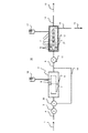
- FIG. 1 is a diagram showing a schematic configuration of a desalination system of the present invention.
- the desalination system 10 includes a biofouling suppression device 3 on the upstream side (front stage) of the reverse osmosis membrane element 2 that filters the treated water 1.
- the bio-fouling suppression device 3 is provided with a supply line 4 for supplying the water 1 to be treated.
- the supply line 4 is provided with a pump (second pump) 5 for supplying the treated water 1 to the biofouling suppression device 3.
- the bio-fouling suppression device 3 includes a container 6 connected to the supply pipe 4 and a columnar body 7 installed inside the container 6. Between the inner wall surface of the container 6 and the columnar body 7, a predetermined gap 8 through which the water to be treated 1 can flow is provided.
- the columnar body 7 is fixed to the inner wall surface of the container 6 with a rectifying member or the like.
- the treated water 1 that has flowed into the biofouling suppression device 3 passes through the gap 8 formed between the surface of the columnar body 7 and the inner wall surface of the container 6. At this time, microorganisms that cause biofouling in the water 1 to be treated grow in a slime form on the surface of the columnar body 7 using the organic matter present in the water 1 to be treated as a nutrient source.
- the water flow means that the water 1 to be treated flows through the gap 8 formed between the surface of the columnar body 7 and the inner wall surface of the container 6. It does not involve passing 1 through the reverse osmosis membrane, that is, filtering the water 1 to be treated through the reverse osmosis membrane.
- biofouling microorganisms grow on the surface of the reverse osmosis membrane constituting the reverse osmosis membrane element 2 in the form of slime, using the organic matter present in the treated water 1 as a nutrient source. That is, biofouling is performed under the condition that the water to be treated 1 passes through the reverse osmosis membrane, that is, in the same way as other fouling in which the organic or inorganic substances in the water 1 to be treated block the surface of the reverse osmosis membrane. It is thought that it occurs under the situation where treated water 1 is filtered through a reverse osmosis membrane.
- biofouling is generated without passing the treated water 1 through the reverse osmosis membrane, that is, without filtering the treated water 1 through the reverse osmosis membrane.
- the biofouling generation mechanism described in the present embodiment is under a situation where the treated water 1 passes through the reverse osmosis membrane, that is, under a situation where the treated water 1 is filtered through the reverse osmosis membrane. This is different from the conventional mechanism of biofouling that blocks the surface of the reverse osmosis membrane.
- biofouling does not occur when the treated water 1 passes through the reverse osmosis membrane, that is, when the treated water 1 is filtered through the reverse osmosis membrane. This is based on the knowledge that it occurs even when the treated water 1 is passed through the gap 8.
- the flow rate of the treated water 1 flowing on the surface of the columnar body 7 of the biofouling suppression device 3 is adjusted. It is important to. The flow rate of the treated water 1 is affected by the flow rate of the treated water 1 and the gap 8 through which the treated water 1 flows.
- Biofouling that occurs on the surface of the columnar body 7 of the biofouling suppression device 3 is a growth of microorganisms using organic substances present in the water 1 to be treated as nutrients. For this reason, the occurrence of biofouling is affected by the number of organic substances and microorganisms. Usually, the number of organic substances and microorganisms present in the water to be treated 1 taken from the same water source does not change greatly when the concentration of the water to be treated 1 does not change greatly. That is, in such a case, the number of existence is determined by the flow rate.
- the occurrence of biofouling requires time for microorganisms to grow using organic matter as a nutrient source. If the flow rate of the water to be treated 1 is too fast or too slow, it is not preferable for the occurrence of biofouling. In particular, in this embodiment, since it is necessary to positively generate biofouling on the surface of the columnar body 7 of the biofouling suppression device 3, this time, that is, the flow rate of the treated water 1 is important. . When the flow rate is large, the above time is shortened, and when the flow rate is small, the above time is lengthened.
- the bio-fouling is effectively applied to the bio-fouling suppression device 3 by making the environment inside the container 6 through which the water to be treated 1 flows and the environment inside the pressure vessel (vessel) 12 described later substantially equal. Can be generated.
- the inside of the container 6 through which the water to be treated 1 flows is a gap 8 between the inner wall surface of the container 6 and the surface of the columnar body 7, and the inside of the pressure vessel 12 through which the water to be treated 1 flows is a pressure container. This is a gap 8 r between the inner wall surface of 12 and the surface of the reverse osmosis membrane element 2.
- the flow rate of the water to be treated 1 flowing on the surface of the columnar body 7 is substantially equal to the flow rate of the water to be treated 1 flowing on the surface of the reverse osmosis membrane element 2.
- the gap 8 and the gap 8r are substantially equal.
- the flow rate of the reverse osmosis membrane element 2f formed in the front stage portion of the reverse osmosis membrane element 2 installed in the pressure vessel 12 is substantially equal.
- the environment inside the bio-fouling suppressing device 3 (container 6) can be brought close to the environment where the occurrence of bio-fouling inside the pressure-resistant container 12 is most remarkable.
- biofouling occurs inside the upstream biofouling suppression device 3. Since biofouling is the growth of microorganisms using organic matter in the water 1 to be treated as a nutrient source, the biofouling is suppressed by generating biofouling inside the biofouling suppression device 3. Organic matter and microorganisms are consumed inside. Thereby, since the organic matter and microorganisms in the to-be-processed water 1 decrease in the surface of the downstream reverse osmosis membrane element 2, generation
- processing such as providing fine irregularities may be performed. This facilitates the fixation of microorganisms that cause biofouling on the surface of the columnar body 7.
- a predetermined coating may be applied to the surface of the columnar body 7.
- the coating material for the columnar body 7 is preferably a material that can easily settle microorganisms or a material that can absorb nutrient sources of microorganisms.
- the organic substance can be adsorbed on the surface of the columnar body 7, and the microorganisms that cause biofouling are easily fixed, and biofouling is likely to occur.
- Al 2 O 3 aluminum oxide (alumina)
- a used reverse osmosis membrane element 2 having reduced permeation performance may be used as the columnar body 7 .
- the environment closer to the inside of the pressure vessel 12 can be reproduced.
- the filtration is not performed when the used reverse osmosis membrane element 2 is used as the columnar body 7 inside the vessel 6.
- the surface of the columnar body 7 may be coated with a material similar to the material of the reverse osmosis membrane forming the reverse osmosis membrane element 2.
- the shape of the columnar body 7 and the shape of the reverse osmosis membrane element 2 are substantially equal.
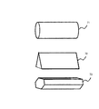
- the shape of the columnar body 7 is not particularly limited as long as it can have a gap 8 through which the water to be treated 1 can flow when installed inside the container 6.
- it may be a polygonal column such as a cylinder 71, a triangular column 72, or a hexagonal column 73 as shown in FIG.
- the container 6 is not particularly limited as long as the treated water 1 can be passed between the container 7 and the columnar body 7, but the container 6 is preferably transparent. Moreover, it is good also as a structure which provides the window which can confirm the state of the columnar body 7 installed in the inside of the container 6 in a part of the container 6. FIG. Thereby, the state of the columnar body 7 installed in the inside of the container 6 can be confirmed from the outside, and the cleaning time and the like can be confirmed.
- the treated water 1 treated in the biofouling suppression device 3 consumes organic matter and microorganisms that cause biofouling, and is discharged to the supply line 9 connected to the container 6.
- a high pressure pump (first pump) 11 is formed in the supply pipeline 9, and the treated water 1 is pressurized and supplied to the pressure vessel 12 by the high pressure pump 11.
- the pressure resistance performance of the container 6 installed on the upstream side of the high pressure pump 11 can be lower than that of the pressure container 12. Therefore, since the structure of the container 6 can be simplified as compared with the pressure resistant container 12, initial investment can be suppressed and maintenance can be easily performed.
- the pump 5 can be composed of a low pressure pump rather than the high pressure pump 11.
- the reverse osmosis membrane element 2 requires a filtration step, but the biofouling suppression device 3 does not require a filtration step and is a water flow step, so the pump 5 is a pump having a lower pressure than the high pressure pump 11. Can be configured.
- a reverse osmosis membrane element 2 for filtering the water 1 to be treated is installed inside the pressure vessel 12 with a gap 8 r formed between the pressure vessel 12 and a concentrated water line 14 and a permeate line. 16 is connected.
- the treated water 1 is pressurized and supplied into the pressure vessel 12 and passes through the gap 8r between the pressure vessel 12 and the reverse osmosis membrane element 2.
- the treated water 1 is pressurized and supplied to the pressure vessel 12, and a part thereof is reverse osmotic filtered by the reverse osmosis membrane element 2 to become permeated water 15 and discharged from the permeated water pipe 16.
- the remaining treated water 1 that has not been subjected to reverse osmosis filtration by the reverse osmosis membrane element 2 becomes concentrated water 13 and is discharged from a concentrated water conduit 14 connected to the pressure vessel 12.
- the pressure vessel 12 is provided with a first cleaning mechanism 17 for cleaning the reverse osmosis membrane element 2.
- a first cleaning mechanism 17 for cleaning the reverse osmosis membrane element 2.
- organic matter and microorganisms that cause biofouling in the treated water 1 are consumed. For this reason, biofouling hardly occurs on the surface of the reverse osmosis membrane element 2.
- microorganisms, organic matter, or inorganic matter that could not be removed cause biofouling and other fouling in the reverse osmosis membrane element 2. Therefore, it is necessary to periodically remove these contaminants. There is.
- the cleaning liquid used in the first cleaning mechanism 17 is not particularly limited as long as microorganisms, organic substances, or inorganic substances can be removed, but a cleaning liquid that does not damage the reverse osmosis membrane element 2 is preferable. Further, a plurality of cleaning liquids may be used properly in order to remove microorganisms, organic substances, or inorganic substances.
- the method of injecting the cleaning liquid is not particularly limited as long as the cleaning liquid can be injected into the pressure-resistant vessel 12, but for example, a diaphragm pump or a gear pump may be used.
- the biofouling suppression device 3 is provided with a second cleaning mechanism 18 for cleaning the columnar body 7. This is because biofouling attached to the columnar body 7 needs to be removed.
- the cleaning liquid used in the second cleaning mechanism 18 is not particularly limited as long as biofouling generated in the columnar body 7 can be removed, but the same cleaning liquid as the cleaning liquid used in the first cleaning mechanism 17 may be used. Although it is good, it is not restricted to this, It is preferable to use especially sodium hypochlorite etc.
- Sodium hypochlorite has a high sterilizing power and oxidizing power, and thus damages the reverse osmosis membrane used for the reverse osmosis membrane element 2 and affects the filtration performance, etc. It cannot be used for cleaning the reverse osmosis membrane element 2.
- the method for injecting the cleaning liquid is not particularly limited as long as the cleaning liquid can be injected into the biofouling suppression device 3 as in the first cleaning mechanism 17.
- a diaphragm pump or a gear pump may be used.
- the desalination system 10 demonstrated by this embodiment installs the part which requires filtration, and the part which does not require filtration, and generates biofouling actively in the part which does not require filtration. . Therefore, it is also effective for cleaning, and a cleaning solution having high sterilizing power and oxidizing power can be used for removing biofouling without considering damage of the reverse osmosis membrane necessary for filtration.
- the bio-fouling suppression device 3 is provided with a bypass line 19 that bypasses the container 6.
- the bypass line 19 is formed by branching from the supply line 4 so as to connect the upstream side and the downstream side of the container 6.
- bypass pipe 19 is provided with a switching valve 20 that switches between the case where the treated water 1 flows into the container 6 and the case where the treated water 1 flows through the bypass pipe 19.
- the water to be treated 1 supplied from the pump 5 can be switched by the switching valve 20 so as to flow through either the container 6 or the bypass pipeline 19.
- the treated water 1 can be supplied to the pressure resistant vessel 12 via the bypass pipe 19 even when the biofouling suppressing device 3 is washed. Thereby, when wash
- the desalination system 10 described in the present embodiment has the biofouling suppression device 3 installed upstream of the reverse osmosis membrane element 2, and biofouling generated on the surface of the reverse osmosis membrane element 2. Is generated in the biofouling suppression device 3.
- biofouling suppression device 3 since the biofouling suppression device 3 does not require pressure resistance as in the case of performing reverse osmosis filtration, it can be easily maintained.
- the present invention can be used in the field of obtaining fresh water by subjecting water to be treated to filtration using a reverse osmosis membrane.
Landscapes
- Chemical & Material Sciences (AREA)
- Engineering & Computer Science (AREA)
- Water Supply & Treatment (AREA)
- Chemical Kinetics & Catalysis (AREA)
- Life Sciences & Earth Sciences (AREA)
- Hydrology & Water Resources (AREA)
- Environmental & Geological Engineering (AREA)
- Organic Chemistry (AREA)
- Nanotechnology (AREA)
- Separation Using Semi-Permeable Membranes (AREA)
Description
2,2f 逆浸透膜エレメント(ろ過装置)
3 バイオファウリング抑制装置
4,9 供給管路
5 ポンプ(第2のポンプ)
6 容器
7 柱状体
8,8r 間隙
10 淡水化システム
11 高圧ポンプ(第1のポンプ)
12 耐圧容器(ろ過装置)
13 濃縮水
14 濃縮水管路
15 透過水
16 透過水管路
17 第1の洗浄機構
18 第2の洗浄機構
19 バイパス管路
20 切替バルブ
Claims (8)
- 被処理水を供給するための供給管路と、前記供給管路に接続される耐圧容器と、前記耐圧容器に収められ、前記被処理水を逆浸透ろ過する逆浸透膜エレメントと、前記逆浸透膜エレメントに接続され、前記被処理水のうち前記逆浸透膜エレメントを透過した透過水を、外部に排出する透過水管路と、前記耐圧容器に接続され、前記被処理水のうち前記逆浸透膜エレメントを透過しない濃縮水を、外部に排出する濃縮水管路と、前記供給管路に形成され、前記耐圧容器に前記被処理水を供給する第1のポンプと、を備える淡水化システムにおいて、
前記第1のポンプの上流側の供給管路に形成される容器と、前記容器に収められ、前記容器との間に前記被処理水を通水できる間隙を有するように設置される柱状体と、前記容器の上流側の前記供給管路に形成され、前記容器に前記被処理水を供給する第2のポンプと、を有するバイオファウリング抑制装置を、更に備える
ことを特徴とする淡水化システム。 - 請求項1記載の淡水化システムにおいて、
前記逆浸透膜エレメントが、複数に分割形成され、
前記容器内の流速が、前記複数に分割形成された逆浸透膜エレメントの上流側1段目近傍の流速とほぼ同等である
ことを特徴とする淡水化システム。 - 請求項1記載の淡水化システムにおいて、
前記柱状体の表面にはアルミナがコーティングされている
ことを特徴とする淡水化システム。 - 請求項1記載の淡水化システムにおいて、
前記第2のポンプの供給圧力が、前記第1のポンプの供給圧力よりも低い
ことを特徴とする淡水化システム。 - 請求項1記載の淡水化システムにおいて、
前記容器は、外部より前記柱状体の表面を視認できる透明な部材を少なくとも一部に有する
ことを特徴とする淡水化システム。 - 請求項1記載の淡水化システムにおいて、
前記耐圧容器には前記逆浸透膜エレメントを洗浄する第1の洗浄機構を備え、前記容器には前記柱状体を洗浄する第2の洗浄機構を備える
ことを特徴とする淡水化システム。 - 請求項1記載の淡水化システムにおいて、
前記容器をバイパスするバイパス管路が、前記容器の上流側と下流側とを結合するように、前記供給管路から分岐して形成され、前記第2のポンプから供給された前記被処理水が、前記容器または前記バイパス管路のいずれかを流れるように流れを変更する切替バルブを有する
ことを特徴とする淡水化システム。 - 逆浸透膜エレメントを有し、被処理水をろ過するろ過装置と、
前記ろ過装置の上流側に配置され、内部でバイオファウリングを発生させることにより、下流側に配置される前記ろ過装置に流入する前記被処理水に存在する有機物を低減するバイオファウリング抑制装置と、を備える
ことを特徴とする淡水化システム。
Priority Applications (2)
| Application Number | Priority Date | Filing Date | Title |
|---|---|---|---|
| JP2014538292A JPWO2014050402A1 (ja) | 2012-09-28 | 2013-08-26 | 淡水化システム |
| CN201380049829.4A CN104661965A (zh) | 2012-09-28 | 2013-08-26 | 淡水化系统 |
Applications Claiming Priority (2)
| Application Number | Priority Date | Filing Date | Title |
|---|---|---|---|
| JP2012-215542 | 2012-09-28 | ||
| JP2012215542 | 2012-09-28 |
Publications (1)
| Publication Number | Publication Date |
|---|---|
| WO2014050402A1 true WO2014050402A1 (ja) | 2014-04-03 |
Family
ID=50387811
Family Applications (1)
| Application Number | Title | Priority Date | Filing Date |
|---|---|---|---|
| PCT/JP2013/072727 Ceased WO2014050402A1 (ja) | 2012-09-28 | 2013-08-26 | 淡水化システム |
Country Status (3)
| Country | Link |
|---|---|
| JP (1) | JPWO2014050402A1 (ja) |
| CN (1) | CN104661965A (ja) |
| WO (1) | WO2014050402A1 (ja) |
Families Citing this family (1)
| Publication number | Priority date | Publication date | Assignee | Title |
|---|---|---|---|---|
| CN105036392A (zh) * | 2015-06-30 | 2015-11-11 | 潍坊友容实业有限公司 | 一种防止反渗透膜生物污染的方法及装置 |
Citations (8)
| Publication number | Priority date | Publication date | Assignee | Title |
|---|---|---|---|---|
| JPS61227840A (ja) * | 1985-03-30 | 1986-10-09 | Suido Kiko Kk | 浄水場汚泥を原料とした水処理用無機系吸着剤の製法 |
| JPH11342308A (ja) * | 1998-03-30 | 1999-12-14 | Toray Ind Inc | 造水ユニット |
| JP2001170622A (ja) * | 1999-12-16 | 2001-06-26 | Nikkiso Co Ltd | 吸着物質の脱着方法、濃縮器、及び濃縮方法 |
| JP2005313034A (ja) * | 2004-04-27 | 2005-11-10 | Miura Co Ltd | 給水システム |
| JP2011125863A (ja) * | 2011-02-04 | 2011-06-30 | Mitsubishi Rayon Co Ltd | ナノ濾過膜の熱水消毒方法 |
| JP2011167689A (ja) * | 2006-08-17 | 2011-09-01 | Housetec Inc | 固形リン除去剤及びそれを備える排水浄化槽 |
| JP2011218267A (ja) * | 2010-04-07 | 2011-11-04 | Toray Ind Inc | 水処理方法および水処理装置 |
| JP2011235235A (ja) * | 2010-05-11 | 2011-11-24 | Miura Co Ltd | 水処理システム |
Family Cites Families (1)
| Publication number | Priority date | Publication date | Assignee | Title |
|---|---|---|---|---|
| JP2011218627A (ja) * | 2010-04-07 | 2011-11-04 | Canon Inc | 記録装置 |
-
2013
- 2013-08-26 JP JP2014538292A patent/JPWO2014050402A1/ja active Pending
- 2013-08-26 CN CN201380049829.4A patent/CN104661965A/zh active Pending
- 2013-08-26 WO PCT/JP2013/072727 patent/WO2014050402A1/ja not_active Ceased
Patent Citations (8)
| Publication number | Priority date | Publication date | Assignee | Title |
|---|---|---|---|---|
| JPS61227840A (ja) * | 1985-03-30 | 1986-10-09 | Suido Kiko Kk | 浄水場汚泥を原料とした水処理用無機系吸着剤の製法 |
| JPH11342308A (ja) * | 1998-03-30 | 1999-12-14 | Toray Ind Inc | 造水ユニット |
| JP2001170622A (ja) * | 1999-12-16 | 2001-06-26 | Nikkiso Co Ltd | 吸着物質の脱着方法、濃縮器、及び濃縮方法 |
| JP2005313034A (ja) * | 2004-04-27 | 2005-11-10 | Miura Co Ltd | 給水システム |
| JP2011167689A (ja) * | 2006-08-17 | 2011-09-01 | Housetec Inc | 固形リン除去剤及びそれを備える排水浄化槽 |
| JP2011218267A (ja) * | 2010-04-07 | 2011-11-04 | Toray Ind Inc | 水処理方法および水処理装置 |
| JP2011235235A (ja) * | 2010-05-11 | 2011-11-24 | Miura Co Ltd | 水処理システム |
| JP2011125863A (ja) * | 2011-02-04 | 2011-06-30 | Mitsubishi Rayon Co Ltd | ナノ濾過膜の熱水消毒方法 |
Also Published As
| Publication number | Publication date |
|---|---|
| JPWO2014050402A1 (ja) | 2016-08-22 |
| CN104661965A (zh) | 2015-05-27 |
Similar Documents
| Publication | Publication Date | Title |
|---|---|---|
| CN103502158B (zh) | 低能量反渗透方法 | |
| JP5804228B1 (ja) | 水処理方法 | |
| KR101342689B1 (ko) | 세라믹 막여과공정의 고압 역세정 장치 및 방법 | |
| JPWO2006057249A1 (ja) | 逆浸透膜法海水淡水化装置 | |
| AU2012355018A1 (en) | Reverse osmosis treatment device and method for cleaning reverse osmosis treatment device | |
| US9238586B2 (en) | Filter cleaning method | |
| JP2011083764A (ja) | 水浄化システムの運転方法及び水浄化システム | |
| KR101928212B1 (ko) | 역삼투막 세정 방법 | |
| WO2016199725A1 (ja) | 淡水製造装置および淡水製造装置の運転方法 | |
| KR20140026116A (ko) | 분리막 세척기능을 갖는 수처리 장치 및 수처리 장치의 분리막 세척방법 | |
| CN105050964B (zh) | 抑制液体系统中的污塞的方法 | |
| JP7580912B2 (ja) | 濃縮システム | |
| WO2015115591A1 (ja) | 生物膜濾過装置、淡水化システム、及び、生物膜濾過装置の洗浄方法 | |
| WO2017168720A1 (ja) | 逆浸透膜処理方法及び逆浸透膜処理設備 | |
| WO2014050402A1 (ja) | 淡水化システム | |
| JP5377553B2 (ja) | 膜ろ過システムとその運転方法 | |
| JP2011078889A (ja) | 濾過部材洗浄システム | |
| JP2016150283A (ja) | 膜処理装置及び膜処理方法 | |
| JP2013163141A (ja) | 膜ろ過システム | |
| JP2008302333A (ja) | 造水方法及びその装置 | |
| WO2012057176A1 (ja) | 水処理方法および造水方法 | |
| CN108128848A (zh) | 一种新型水净化处理方法 | |
| RU2434812C1 (ru) | Мембранная установка для очистки воды | |
| JP2015160177A (ja) | 前処理装置、及びそれを用いた海水淡水化装置 | |
| JP2006255708A (ja) | 中空糸膜の逆洗方法及び中空糸膜水処理装置 |
Legal Events
| Date | Code | Title | Description |
|---|---|---|---|
| 121 | Ep: the epo has been informed by wipo that ep was designated in this application |
Ref document number: 13842311 Country of ref document: EP Kind code of ref document: A1 |
|
| ENP | Entry into the national phase |
Ref document number: 2014538292 Country of ref document: JP Kind code of ref document: A |
|
| WWE | Wipo information: entry into national phase |
Ref document number: P256/2015 Country of ref document: AE |
|
| NENP | Non-entry into the national phase |
Ref country code: DE |
|
| 122 | Ep: pct application non-entry in european phase |
Ref document number: 13842311 Country of ref document: EP Kind code of ref document: A1 |