WO2014049669A1 - 放射線撮影装置 - Google Patents
放射線撮影装置 Download PDFInfo
- Publication number
- WO2014049669A1 WO2014049669A1 PCT/JP2012/006251 JP2012006251W WO2014049669A1 WO 2014049669 A1 WO2014049669 A1 WO 2014049669A1 JP 2012006251 W JP2012006251 W JP 2012006251W WO 2014049669 A1 WO2014049669 A1 WO 2014049669A1
- Authority
- WO
- WIPO (PCT)
- Prior art keywords
- image
- imaging
- subtraction
- tomographic
- subject
- Prior art date
- Legal status (The legal status is an assumption and is not a legal conclusion. Google has not performed a legal analysis and makes no representation as to the accuracy of the status listed.)
- Ceased
Links
Images






Classifications
-
- A—HUMAN NECESSITIES
- A61—MEDICAL OR VETERINARY SCIENCE; HYGIENE
- A61B—DIAGNOSIS; SURGERY; IDENTIFICATION
- A61B6/00—Apparatus or devices for radiation diagnosis; Apparatus or devices for radiation diagnosis combined with radiation therapy equipment
- A61B6/52—Devices using data or image processing specially adapted for radiation diagnosis
- A61B6/5211—Devices using data or image processing specially adapted for radiation diagnosis involving processing of medical diagnostic data
- A61B6/5229—Devices using data or image processing specially adapted for radiation diagnosis involving processing of medical diagnostic data combining image data of a patient, e.g. combining a functional image with an anatomical image
- A61B6/5235—Devices using data or image processing specially adapted for radiation diagnosis involving processing of medical diagnostic data combining image data of a patient, e.g. combining a functional image with an anatomical image combining images from the same or different ionising radiation imaging techniques, e.g. PET and CT
-
- A—HUMAN NECESSITIES
- A61—MEDICAL OR VETERINARY SCIENCE; HYGIENE
- A61B—DIAGNOSIS; SURGERY; IDENTIFICATION
- A61B6/00—Apparatus or devices for radiation diagnosis; Apparatus or devices for radiation diagnosis combined with radiation therapy equipment
- A61B6/02—Arrangements for diagnosis sequentially in different planes; Stereoscopic radiation diagnosis
- A61B6/025—Tomosynthesis
-
- A—HUMAN NECESSITIES
- A61—MEDICAL OR VETERINARY SCIENCE; HYGIENE
- A61B—DIAGNOSIS; SURGERY; IDENTIFICATION
- A61B6/00—Apparatus or devices for radiation diagnosis; Apparatus or devices for radiation diagnosis combined with radiation therapy equipment
- A61B6/48—Diagnostic techniques
- A61B6/481—Diagnostic techniques involving the use of contrast agents
-
- A—HUMAN NECESSITIES
- A61—MEDICAL OR VETERINARY SCIENCE; HYGIENE
- A61B—DIAGNOSIS; SURGERY; IDENTIFICATION
- A61B6/00—Apparatus or devices for radiation diagnosis; Apparatus or devices for radiation diagnosis combined with radiation therapy equipment
- A61B6/50—Apparatus or devices for radiation diagnosis; Apparatus or devices for radiation diagnosis combined with radiation therapy equipment specially adapted for specific body parts; specially adapted for specific clinical applications
- A61B6/504—Apparatus or devices for radiation diagnosis; Apparatus or devices for radiation diagnosis combined with radiation therapy equipment specially adapted for specific body parts; specially adapted for specific clinical applications for diagnosis of blood vessels, e.g. by angiography
Definitions
- the present invention relates to a radiation imaging apparatus that acquires an image by irradiating a subject with radiation.
- a medical institution is equipped with a radiation imaging apparatus for imaging a subject by irradiating radiation.
- a radiation imaging apparatus includes a radiation source 53 that emits radiation and an FPD 54 that detects the radiation, as shown in FIG.
- a top plate 52 on which the subject M is placed is provided between the radiation source 53 and the FPD 54 (see, for example, Non-Patent Document 1).
- the projection image acquired in this manner is a projection image obtained by projecting a three-dimensional subject image onto a plane.
- subtraction imaging as an imaging method using such a radiation imaging apparatus.
- subtraction imaging there is a configuration in which imaging is performed twice before and after angiographic agent administration, and an image obtained before administration is subtracted from an image obtained after administration.
- An angiographic agent is a drug that clarifies blood vessels on an image in radiography. Therefore, it seems that an image in which blood vessels are clearly reflected can be obtained by performing radiography by administering an angiographic contrast agent. However, structures other than blood vessels are also reflected in the actually acquired image. Therefore, only an image in which a blood vessel and other structures are simultaneously captured can be obtained by simply administering an angiographic contrast medium and performing imaging. Such an image cannot be said to be suitable for diagnosis.
- the subject is radiographed before the angiographic agent is administered. Then, if the difference between the two images obtained before and after the administration of the angiographic contrast agent is obtained, an image in which the blood vessels are more emphasized can be obtained. Structures other than blood vessels in the subject are shown in common in the image obtained after the administration of the angiographic contrast agent and the image obtained before the administration, and the images of these structures are mutually connected by image difference processing. This is because they cancel out and disappear.
- the conventional configuration has the following problems. That is, in the conventional subtraction image, the position of the lesion cannot be accurately determined.
- a structure called a pseudotumor may be generated around the artificial joint. This pseudotumor can interfere with joint movement if left untreated. Therefore, it is necessary to observe by radiography whether a subject has undergone artificial joint replacement surgery for a pseudotumor. It is known that a blood vessel is formed so as to cover a pseudotumor. Therefore, in order to observe a pseudotumor, acquisition of a subtraction image using the above-described angiographic contrast agent is performed. That is, a blood vessel image associated with a pseudotumor is imaged by acquiring a difference between two images taken before and after administration of an angiographic contrast agent.
- the subtraction image obtained with the conventional configuration is an image based on a projection image obtained by projecting a projection image obtained by projecting a three-dimensional subject image onto a plane. Therefore, the stereoscopic information of the subject is lost from the subtraction image. This can make it difficult for the operator to diagnose.
- FIG. 13 illustrates this problem.
- the left side of FIG. 13 shows a case where a small pseudotumor is present on the side close to the radiation source 53 in the body of the subject. Since the radiation beam emitted from the radiation source 53 spreads radially, the image of the pseudotumor ps is greatly enlarged and reflected in the FPD 54.
- the right side of FIG. 13 is a case where there is a large pseudotumor ps on the side close to the FPD 54 in the body of the subject. In this case, since the image of the pseudo tumor ps is located far from the radiation source 53, it is reflected on the FPD 54 without being enlarged so much.
- the pseudotumor ps on the left side of FIG. 13 is smaller than that on the right side.
- the enlargement rates when the pseudotumor ps appears in the image are different from each other. For this reason, the pseudo tumor ps that appears in the image in the left side of FIG. 13 and the pseudo tumor ps that appears in the image in the right side of FIG. 13 may have the same size.
- the size of the pseudo tumor reflected in the subtraction image is not determined according to the position where the pseudo tumor is generated, it is difficult to accurately diagnose the progress of the pseudo tumor from the subtraction image.
- the present invention has been made in view of such circumstances, and an object of the present invention is to provide a radiographic apparatus capable of acquiring a subtraction image capable of performing an accurate diagnosis.
- a radiation imaging apparatus includes a radiation source that irradiates radiation, a detection unit that detects radiation transmitted through a subject, an image generation unit that generates an original image based on a detection signal of the detection unit, Based on the original image obtained by repeating the imaging for continuously shooting the original image while changing the imaging direction with respect to the subject, the difference between the first imaging and the second imaging and the tomographic image and And a subtraction image acquisition means for acquiring the subtraction image.
- the tomographic image is generated twice, and the difference between the first imaging result and the second imaging result is acquired, thereby subtracting the subtraction image.
- the image is acquired as an image.
- the tomographic image captures the lesion with an accurate size regardless of the position of the lesion. That is, in the tomographic image, the magnification of the image does not change depending on whether the lesion is on the radiation source side or the detection means side.
- a subtraction image having such characteristics is more suitable for diagnosis than an image obtained by a conventional method. Therefore, according to the present invention, the progression of pseudotumor can be accurately determined.
- the subtraction image is a tomographic image, the structure of the subject does not appear to overlap and an image with high contrast can be acquired.
- the subtraction image acquisition unit can employ a configuration in which a subtraction image is generated by performing difference processing after generating two tomographic images. This configuration is referred to as a configuration in which tomographic image generation is performed first.
- the subtraction image acquisition unit includes a plurality of original images obtained by the first photographing and a plurality of original images obtained by the second photographing. It is more desirable to have tomographic image generation means for generating two tomographic images with different imaging times and subtraction means for performing subtraction processing between the two tomographic images generated by the tomographic image generation means.
- the above-described configuration shows a specific example of the configuration in which the tomographic image is generated first in the present invention. Two tomographic images having different photographing times are generated from each of the plurality of original images obtained by the first photographing and the plurality of original images obtained by the second photographing, and between the two tomographic images. If the subtraction image is generated by performing the subtracting process in, the target subtraction image can be generated more reliably.
- the subtraction image acquisition means adopts a configuration of generating a subtraction image by generating a tomographic image after performing a difference process between the original images. You can also. This configuration is referred to as a configuration in which the difference process is performed first.
- the above-described configuration more specifically represents the radiation imaging apparatus of the present invention. If the tomographic image is acquired after performing the difference processing, the target subtraction image can be generated more reliably.
- the subtraction image acquisition unit includes a subtraction unit that performs subtraction processing between two original images that have different imaging times and have the same imaging direction with respect to the subject. It is more desirable to include a tomographic image generation means for generating a tomographic image based on the image.
- the above-described configuration shows a specific example of the configuration in which the differential processing in the present invention is performed first. If a subtraction process is performed between two original images with different imaging times and the same imaging direction with respect to the subject, and a tomographic image is generated based on the acquired subtracted image, the object is more reliably obtained.
- the subtraction image can be generated.
- the radiation source moving means for moving the radiation source relative to the subject
- the detector moving means for moving the detection means relative to the subject
- the present invention can be applied to a so-called tomosynthesis apparatus that takes a tomographic image by moving a radiation source and a detection means in opposite directions.
- the present invention can also be applied to a so-called long imaging apparatus that takes a tomographic image by moving the radiation source and the detection means in the same direction.
- a subtraction image with excellent visibility can be acquired as compared with the case where the present invention is applied to a CT apparatus. This is because these apparatuses can be equipped with a high-performance radiation detector as compared with the CT apparatus.
- the original image that is used when the subtraction image acquisition unit generates the subtraction image is obtained by the first imaging before the angiography agent administration and the second imaging after the administration. More desirable.
- the above-described configuration more specifically represents the state of the inspection using the radiation imaging apparatus of the present invention.
- the present invention is also effective when acquiring a subtraction image indicating the difference between before and after angiographic administration.
- the above-described configuration more specifically represents the state of the inspection using the radiation imaging apparatus of the present invention. According to the present invention, it is possible to reliably photograph a subject in which a metal is embedded. That is, unlike the inspection using MRI, according to the configuration of the present invention, the metal does not have heat during imaging, and an image can be acquired safely.
- the above-described configuration more specifically represents the state of the inspection using the radiation imaging apparatus of the present invention.
- the present invention is suitable for examination of a subject in which a metal is embedded. That is, the present invention is suitable for observing whether a pseudotumor is growing in a subject in which a metal artificial joint is embedded.
- the subtraction image is acquired as the tomographic image by performing the imaging twice to generate the tomographic image and acquiring the difference between the first imaging result and the second imaging result. It has become. According to such a configuration, it becomes easier for the surgeon to accurately grasp the position and size of the lesioned part as compared with the conventional method of subtracting projection images and generating a subtraction image.
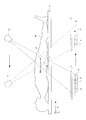
- FIG. 1 is a functional block diagram illustrating a configuration of an X-ray imaging apparatus according to Embodiment 1.
- FIG. FIG. 3 is a schematic diagram for explaining a tomographic image acquisition principle in the X-ray imaging apparatus according to Embodiment 1;
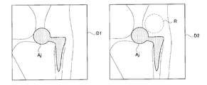
- 6 is a schematic diagram illustrating a tomographic image according to Embodiment 1.
- FIG. 6 is a schematic diagram illustrating a tomographic image according to Embodiment 1.
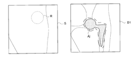
- FIG. 6 is a schematic diagram for explaining a subtraction image according to Embodiment 1.
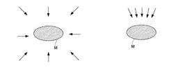
- FIG. FIG. 6 is a schematic diagram for explaining an effect according to the first embodiment.
- 3 is a flowchart for explaining the operation of the X-ray imaging apparatus according to Embodiment 1;
- FIG. 10 is a schematic diagram for explaining the operation of the radiation imaging apparatus according to the third embodiment.
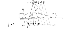
- FIG. 10 is a schematic diagram for explaining a tomographic image acquisition principle in an X-ray imaging apparatus according to Embodiment 3;
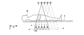
- FIG. 10 is a schematic diagram for explaining a tomographic image acquisition principle in an X-ray imaging apparatus according to Embodiment 3;
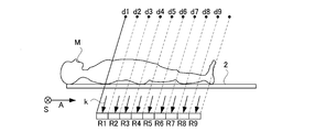
- FIG. 10 is a schematic diagram for explaining a tomographic image acquisition principle in an X-ray imaging apparatus according to Embodiment 3;
- It is a schematic diagram explaining the X-ray imaging apparatus of a conventional structure.
- It is a schematic diagram explaining the problem of the X-ray imaging apparatus of a conventional structure.
- the X-ray in an Example is corresponded to the radiation of the structure of this invention.
- FPD is an abbreviation for flat panel X-ray detector (flat panel detector).
- the X-ray imaging apparatus 1 of the present invention is for follow-up after an artificial joint replacement operation.
- FIG. 1 is a functional block diagram illustrating the configuration of the X-ray imaging apparatus 1 according to the first embodiment.
- the X-ray imaging apparatus 1 according to the first embodiment includes a top plate 2 on which a subject M that is a target of X-ray tomography is placed, and an upper portion of the top plate 2
- An X-ray tube 3 that irradiates the subject M with a cone-shaped X-ray beam toward the subject M, and a lower portion of the top 2 (the other side of the top).
- the X-ray tube 3 and the FPD 4 are respectively connected to the FPD 4 that detects X-rays transmitted through the subject M, and the center axis of the cone-shaped X-ray beam and the center point of the FPD 4 are always coincident with each other.
- a synchronous movement mechanism 7 that moves synchronously in opposite directions across the region of interest
- a synchronous movement control unit 8 that controls the synchronous movement mechanism 7, and scattered X-rays provided so as to cover the X-ray detection surface that detects the X-rays of the FPD 4 And an X-ray grid 5 that absorbs.
- the top plate 2 is disposed at a position sandwiched between the X-ray tube 3 and the FPD 4.
- the X-ray tube 3 corresponds to the radiation source of the present invention
- the FPD 4 corresponds to the detection means of the present invention.
- the synchronous movement control unit 8 corresponds to the movement control means of the present invention.
- the synchronous movement mechanism 7 includes an X-ray tube movement mechanism 7a that moves the X-ray tube 3 in the body axis direction A with respect to the subject M, and an FPD movement mechanism that moves the FPD 4 in the body axis direction A with respect to the subject M. 7b.
- the synchronous movement control unit 8 includes an X-ray tube movement control unit 8a that controls the X-ray tube movement mechanism 7a and an FPD movement control unit 8b that controls the FPD movement mechanism 7b.
- the synchronous movement control unit 8 moves the X-ray tube 3 and the FPD 4 in directions opposite to each other when the original images P1 and P2 are continuously shot.
- the X-ray tube moving mechanism 7a corresponds to the radiation source moving means of the present invention
- the FPD moving mechanism 7b corresponds to the detector moving means of the present invention.
- the X-ray tube 3 is configured to repeatedly irradiate the subject M with a cone-shaped and pulsed X-ray beam in accordance with the control of the X-ray tube control unit 6.
- the X-ray tube 3 is provided with a collimator that collimates the X-ray beam into a cone shape that is a pyramid.
- the X-ray tube 3 and the FPD 4 generate imaging systems 3 and 4 that capture an X-ray projection image.
- the X-ray tube control unit 6 controls the X-ray tube 3 according to set values indicating tube current, tube voltage, pulse width, etc. when the X-ray tube 3 is controlled.
- the X-ray tube control unit 6 corresponds to the radiation source control means of the present invention.
- the synchronous movement mechanism 7 is configured to move the X-ray tube 3 and the FPD 4 in synchronization with the subject M.
- the synchronous movement mechanism 7 linearly moves the X-ray tube 3 along a linear trajectory (longitudinal direction of the top 2) parallel to the body axis direction A of the subject M according to the control of the synchronous movement control unit 8.
- the moving direction of the X-ray tube 3 and the FPD 4 coincides with the longitudinal direction of the top 2.
- the cone-shaped X-ray beam irradiated by the X-ray tube 3 is always irradiated toward the region of interest of the subject M.
- the X-ray irradiation angle is determined by the X-ray tube 3.
- the initial angle is changed from ⁇ 20 ° to the final angle of 20 °.
- Such an X-ray irradiation angle change is performed by the X-ray tube tilting mechanism 9.
- the X-ray tube tilt control unit 10 is provided for the purpose of controlling the X-ray tube tilt mechanism 9.
- the X-ray imaging apparatus 1 further includes a main control unit 25 that controls the respective control units 6, 8, 10, 11, and 12 and a display unit 27 that displays the subtraction image S. I have.
- the main control unit 25 is constituted by a CPU, and realizes the control units 6, 8, 10 and the later-described units 11, 12 by executing various programs.
- the storage unit 23 stores all data related to control of the X-ray imaging apparatus 1 such as parameters related to control of the X-ray tube 3.
- the console 26 allows the operator to input each operation on the X-ray imaging apparatus 1.
- the synchronous movement mechanism 7 synchronizes with the linear movement of the X-ray tube 3 described above, and causes the FPD 4 provided at the lower part of the top 2 to move in the body axis direction A (the longitudinal direction of the top 2) of the subject M. Move straight ahead.
- the moving direction is opposite to the moving direction of the X-ray tube 3.
- a cone-shaped X-ray beam whose focal position and irradiation direction change as the X-ray tube 3 moves is always received by the entire surface of the X-ray detection surface of the FPD 4. Yes.
- the FPD 4 acquires, for example, 74 projected images while moving in synchronization with the X-ray tube 3 in the opposite directions.
- the imaging systems 3 and 4 are opposed to the position indicated by the alternate long and short dash line illustrated in FIG. 1 through the position indicated by the broken line with the position of the solid line as the initial position. That is, a plurality of X-ray projection images are taken while changing the positions of the X-ray tube 3 and the FPD 4.
- the central axis of the cone-shaped X-ray beam during imaging always coincides with the center point of the FPD 4.
- the center of the FPD 4 moves straight, but this movement is in the direction opposite to the movement of the X-ray tube 3. That is, the X-ray tube 3 and the FPD 4 are moved in the body axis direction A synchronously and in directions opposite to each other.
- an image generation unit 11 that generates a continuously projected image while moving the X-ray tube 3 and the FPD 4 in opposite directions based on a detection signal output from the FPD 4 is provided at the subsequent stage of the FPD 4.
- a further stage of the image generation unit 11 includes a subtraction image generation unit 12 that generates a subtraction image S that is a difference image that is a tomographic image.
- the image generation unit 11 generates original images P1 and P2 based on the detection signal of the FPD 4.
- the subtraction image generation unit 12 generates a subtraction image S by generating two tomographic images D1 and D2 and then performing a difference process.
- the configuration of Example 1 assumes follow-up after an artificial joint replacement operation.
- the original images P1 and P2 and the tomographic images D1 and D2 that are the basis when the subtraction image S is generated include a metal artificial joint.
- the image generation unit 11 corresponds to the image generation unit of the present invention
- the subtraction image generation unit 12 corresponds to the subtraction image generation unit of the present invention.
- the subtraction image generation unit 12 performs the first imaging based on the original images P1 and P2 obtained by repeating the imaging for continuously shooting the original images P1 and P2 twice while changing the imaging direction with respect to the subject M.
- a subtraction image S that is a difference between the second imaging and is a tomographic image is acquired.
- the subtraction image generation unit 12 includes two tomographic images D1 and D2 having different shooting times from a plurality of original images P1 obtained by the first shooting and a plurality of original images P2 obtained by the second shooting.
- a tomographic image generation unit 12a that generates D2 and an image subtraction unit 12b that performs subtraction processing between the two tomographic images D1 and D2 generated by the tomographic image generation unit 12a are provided.
- the tomographic image generation unit 12a corresponds to the tomographic image generation means of the present invention.
- the image subtracting unit 12b corresponds to the subtracting means of the present invention.
- FIG. 2 is a diagram illustrating a tomographic image acquisition method of the X-ray imaging apparatus according to the first embodiment.
- a virtual plane reference cut section MA
- top plate 2 horizontal with respect to the vertical direction
- the FPD 4 is synchronized with the opposite direction of the X-ray tube 3 in accordance with the irradiation direction of the cone-shaped X-ray beam B by the X-ray tube 3 so as to be projected onto the fixed points p and q of the X-ray detection surface of the FPD 4.
- a series of original images P1 and P2 are generated by the image generator 11 while being moved.
- the projected image of the subject M is reflected while changing the position.
- images for example, fixed points p and q
- the point I not located on the reference cut surface MA is reflected as a point i in a series of subject M images while changing the projection position on the FPD 4.
- a point i is blurred without forming an image when the X-ray projection image is superimposed on the tomographic image generation unit 12a.
- an X-ray tomographic image in which only an image positioned on the reference cut surface MA of the subject M is reflected is obtained.
- the projected images are simply superimposed, a tomographic image at the reference cut surface MA is obtained.
- the tomographic image generation unit 12a can obtain a similar tomographic image even at an arbitrary cut surface horizontal to the reference cut surface MA.
- the projection position of the point i moves in the FPD 4, but this moving speed increases as the separation distance between the point I before projection and the reference cut surface MA increases.
- reconstruction is performed while shifting the acquired series of subject M images in the body axis direction A at a predetermined pitch, and a tomographic image at a cutting plane parallel to the reference cutting plane MA is obtained. It is done.
- Such a series of tomographic image reconstruction is performed by the tomographic image generation unit 12a.
- the tomographic image generation unit 12a generates a tomographic image for each of the cut surfaces parallel to each other based on the principle described above.
- FIG. 3 shows each cut surface when the tomographic image generation unit 12a generates a tomographic image. As can be seen from FIG. 3, each of the cut surfaces is parallel to the top plate 2.
- FIG. 4 illustrates tomographic images D1 and D2 generated by the tomographic image generation unit 12a.
- the two tomographic images D1 and D2 in FIG. 4 represent the same cross-sectional position when the subject M is cut along a common cut surface. Therefore, the subject images shown in the two tomographic images D1 and D2 are generally the same. That is, the artificial joint Aj previously embedded in the subject is reflected in both the tomographic images D1 and D2. Since the artificial joint Aj is made of metal, it does not transmit X-rays. Therefore, the artificial joint Aj is reflected very darkly in the tomographic images D1 and D2.
- the tomographic image D1 and the tomographic image D2 are taken under the same X-ray irradiation conditions.
- the difference between the tomographic image D1 and the tomographic image D2 is the presence or absence of administration of an angiographic contrast agent. That is, the tomographic image D1 is taken before the angiographic contrast agent is administered to the subject M, and the tomographic image D2 is taken after the angiographic contrast agent is administered to the subject M. ing. Since a tomographic image cannot be obtained unless a plurality of original images P1 and P2 are continuously shot, it is necessary to perform continuous shooting twice to obtain the tomographic images D1 and D2. As such a photographing method, for example, the photographing of the tomographic image D1 is completed by continuously taking the original image P1 while moving the imaging systems 3 and 4 from the position of the solid line in FIG.
- the imaging of the tomographic image D2 can be completed by continuously shooting the original image P2 while moving the imaging systems 3 and 4 from the position of the one-dot chain line to the position of the solid line. That is, the tomographic images D1 and D2 can be taken by reciprocating the imaging systems 3 and 4 once.
- the left side of FIG. 5 represents a subtraction image S that is a difference obtained by subtracting the tomographic image D1 from the tomographic image D2.
- the subtraction image S an image that appears in the tomographic image D2 but does not appear in the tomographic image D1 appears with emphasis.
- the tomographic image D2 is an image after administration of the angiographic contrast agent
- the blood vessel of the subject M is emphasized more than the tomographic image D1.
- a blood vessel R around the pseudotumor is reflected.
- the blood vessel R is emphasized by the angiographic contrast agent, and is not clearly reflected in the tomographic image D1 before the angiographic contrast agent.
- the subtraction image S is an image in which the blood vessel R is emphasized as shown on the left side of FIG.
- structures such as the artificial joint Aj that are reflected in the tomographic images D1 and D2 are canceled out by the image subtraction process, and thus are not noticeable in the subtraction image S.
- the subtraction image S is an image between tomographic images
- the subtraction image S itself is also a tomographic image.
- the original images P1 and P2 that are the basis for generating the subtraction image S are obtained by the first imaging before the administration of the angiographic contrast agent and the second imaging after the administration. From these facts, the subtraction image S is an image in which blood vessels located on a certain cut surface are emphasized.
- the greatest feature of the present invention is that a subtraction image is generated by subtracting tomographic images. If it says from this principle, the acquisition means of a tomographic image will not be restricted especially.
- the present invention can be applied to a CT apparatus.
- the CT apparatus is an apparatus that acquires a tomographic image by rotating the X-ray tube 3 and the radiation detector around the subject M. This is different from the configuration of FIG. 1 in which the X-ray tube 3 and the FPD 4 are translated.
- the configuration of the first embodiment described in FIG. 1 is superior to the CT apparatus, and this point will be specifically described.
- the CT apparatus since it is necessary for the CT apparatus to rotate the radiation detector at a high speed, there is a problem that the radiation detector cannot be made so high in performance.
- the FPD 4 used for spot imaging in which the X-ray tube 3 and the FPD 4 are fixed can be used as it is. Therefore, according to the configuration of FIG. 1, a radiation detector having higher sensitivity and higher spatial resolution than that of the CT apparatus can be employed, and therefore, a subtraction image S having higher resolution than that of the CT apparatus can be acquired.
- the CT apparatus has a significant problem that the tomographic image is likely to be forged when a metal such as an artificial joint appears in the field of view.
- the CT apparatus acquires tomographic images by continuously taking images while rotating the X-ray tube 3 and the radiation detector once. At this time, in the CT apparatus, a calculation is performed for grasping the subject image captured while changing the form of the image taken in each direction and acquiring the three-dimensional structure of the subject M.
- Metals generally transmit X-rays with a certain transmittance. If this transmittance is not accurately known, a tomographic image that faithfully represents the inside of the subject M cannot be acquired.
- metal is reflected in a plurality of images obtained by rotating the X-ray tube 3 and the radiation detector once in the CT apparatus. Since metal absorbs too much X-rays compared to other parts of the subject M, the dose of X-rays transmitted through the metal is negligible. This slight dose is outside the range in which the X-ray dose, which is the specification of the radiation detector, can be measured accurately. This is because the detection sensitivity of the radiation detector is optimized so as to photograph an organ in the subject and is not intended to photograph a metal. Therefore, a metal that is much less likely to transmit X-rays than the structure of the subject M is not represented by an ideal pixel value on the image.
- the false image which appears around this artificial joint Aj can be reduced.
- the moving direction of the imaging systems 3 and 4 is limited, and the imaging direction when capturing the original images P1 and P2 does not change much. . If it does so, the discrepancy of the data which arises when reconstructing original images P1 and P2 will be controlled, and a tomographic image with few false images can be acquired.
- the false image is generated from various directions because the subject M containing metal is photographed. For example, even if the subject M containing metal is photographed from one direction, a false image is not generated in the obtained image.
- the tomographic image can be acquired in a state in which the imaging directions are similar (for example, the right side of FIG. 6) unlike the configuration in which the imaging is uniformly performed from all directions as in the CT apparatus (for example, see the left side in FIG. 6). reference). That is, according to the configuration of the first embodiment, the imaging mode is closer to the case of imaging from one direction compared to the CT apparatus, and the generation of false images can be suppressed.
- X-ray imaging apparatus 1 ⁇ Operation of X-ray imaging apparatus 1>
- the operation of the X-ray imaging apparatus will be described with reference to FIG.
- the subject M is placed on the top 2 (subject placement step S1).
- X-ray irradiation is started from the X-ray tube 3 (first imaging step S2).
- the imaging at this time is imaging before angiographic contrast agent administration.
- the imaging systems 3 and 4 are moved from the solid line position shown in FIG. 1 to the one-dot chain line position via the broken line position.
- 74 original images P1 are acquired and transmitted to the tomographic image generator 12a.
- an angiographic agent is administered by injection to the subject M (angiographic agent administration step S3).
- angiographic agent administration step S3 When the operator gives an instruction to start the second imaging to the X-ray imaging apparatus through the console 26, X-ray irradiation is started from the X-ray tube 3 (second imaging step S4).
- photography at this time is imaging
- the imaging systems 3 and 4 are moved from the position of the one-dot chain line shown in FIG. 1 to the position of the solid line via the position of the broken line. During this period, 74 original images P2 are acquired and transmitted to the tomographic image generator 12a.
- the X-ray tube 3 is subjected to the same control from the X-ray tube controller 6 as in the first imaging.
- this configuration may be changed so that the control conditions of the X-ray tube 3 are different between the first imaging and the second imaging.
- the subtraction image generation unit 12 receives the original image P1 related to the first shooting and the original image P2 related to the second shooting.
- the subtraction image generation unit 12 generates tomographic images D1 and D2 based on these. This operation is executed by the tomographic image generation unit 12 a attached to the subtraction image generation unit 12.
- the tomographic image generation unit 12a generates a plurality of tomographic images D1 having parallel cut surfaces described with reference to FIG. 3 from the original image P1 related to the first imaging. Similarly, the tomographic image generation unit 12a generates a plurality of tomographic images D2 having the mutually parallel cut surfaces described with reference to FIG. 3 from the original image P2 related to the second imaging. At this time, the tomographic image generation unit 12a generates the same number of tomographic images D2 as the tomographic images D1. Moreover, these tomographic images D1 and D2 correspond to each other. That is, in each tomographic image D1, a tomographic image D2 having the same field at the same cutting position as the visual field range is generated.
- the tomographic images D1 and D2 generated by the tomographic image generation unit 12a are sent to the image subtraction unit 12b attached to the subtraction image generation unit 12.
- the image subtraction unit 12b performs subtraction processing on the tomographic images D1 and D2 corresponding to each other. That is, the image subtracting unit 12b subtracts the corresponding tomographic image D1 before administration of the angiographic contrast agent from the tomographic image D2 after administration of the angiographic contrast agent. Thereby, the subtraction image S which is a tomographic image is generated.
- the subtraction image S is displayed on the display unit 27, and the operation of the X-ray imaging apparatus ends.
- the imaging for generating the tomographic images D1 and D2 is performed twice, and the difference between the first imaging result and the second imaging result is acquired.
- the image S is acquired as a tomographic image.
- the tomographic images D1 and D2 capture the lesion with an accurate size regardless of the position of the lesion. That is, in the tomographic images D1 and D2, the magnification of the image does not change depending on whether the lesion is on the X-ray tube 3 side or the FPD 4 side.
- the subtraction image S having such characteristics is more suitable for diagnosis than an image obtained by a conventional method. Therefore, according to the present invention, the progression of pseudotumor can be accurately determined.
- the projection image includes various structures in the subject overlapping each other, the image is not clear compared to the tomographic images D1 and D2.
- the subtraction image S is a tomographic image, the structure of the subject M does not appear to overlap and an image with high contrast can be acquired.
- the above configuration shows a specific example of the configuration in which the tomographic images D1 and D2 are generated first in the present invention.
- Two tomographic images D1, D2 with different shooting times are generated from the plurality of original images obtained by the first shooting and the plurality of original images P1, P2 obtained by the second shooting, respectively. If the subtraction image S is generated by performing subtraction processing between the tomographic images D1 and D2, the target subtraction image S can be generated more reliably.
- the above configuration more specifically represents the X-ray imaging apparatus 1 of the present invention. That is, according to the present invention, the present invention can be applied to a so-called tomosynthesis apparatus that takes a tomographic image by moving the X-ray tube 3 and the FPD 4 in opposite directions.
- a subtraction image S with excellent visibility can be acquired as compared with the case where the present invention is applied to a CT apparatus. This is because the tomosynthesis apparatus can be equipped with a high-performance radiation detector as compared with the CT apparatus.
- the above-described configuration more specifically represents the state of the inspection using the X-ray imaging apparatus 1 of the present invention.
- imaging can be reliably performed on the subject M in which metal is embedded. That is, unlike the inspection using MRI, according to the configuration of the present invention, the metal S does not have heat during imaging, and the image S can be acquired safely.
- the above-described configuration more specifically represents the state of the inspection using the X-ray imaging apparatus 1 of the present invention.
- the present invention is suitable for examination of a subject M in which a metal is embedded. That is, the present invention is suitable for observing whether a pseudotumor is growing on the subject M in which a metal artificial joint is embedded.
- the configuration of the second embodiment is almost the same as the configuration of the first embodiment. The difference is the operation of the subtraction image generator 12.
- the subtraction image generation unit 12 operates to perform the subtraction process after generating the tomographic image.
- the reverse is true.
- the subtraction image generation unit 12 performs a subtraction process on the original image P1 related to the first shooting and the original image P2 related to the second shooting.
- the number of original images P1 related to the first shooting and the number of original images P2 related to the second shooting are 74, the same.
- the original image P1 related to the first shooting and the original image P2 related to the second shooting correspond to each other. That is, in each of the original images P1 related to the first imaging, the original image P2 that is captured from the same imaging direction so that the same part of the subject M is in the visual field range is acquired by the second imaging. It is.
- the subtraction image generation unit 12 employs a configuration in which the subtraction image S is generated by generating a tomographic image after performing a difference process between the original images.
- the subtraction image generation unit 12 according to the second embodiment performs an image subtraction unit that performs subtraction processing between two original images P1 and P2 that have different imaging times and have the same imaging direction with respect to the subject M. 12b and a tomographic image generation unit 12a that generates a tomographic image based on the subtracted image.
- the image subtraction unit 12b performs subtraction processing on the original images P1 and P2 corresponding to each other. That is, the image subtracting unit 12b subtracts the corresponding original image P1 from the original image P2. 74 original images after subtraction processing are acquired, and the imaging directions with respect to the subject are different among the images.
- the original image after the subtraction process is sent to the tomographic image generation unit 12a.
- the tomographic image generation unit 12a generates a plurality of tomographic images having cut surfaces parallel to each other described with reference to FIG. 3 from the original image after the subtraction process.
- the above-described configuration shows a specific example of the configuration in which the differential processing in the present invention is performed first.
- a subtraction process may be performed between two original images P1 and P2 having different imaging times and the same imaging direction with respect to the subject M, and a tomographic image may be generated based on the acquired subtracted image.
- the target subtraction image S can be generated.
- the configuration of the third embodiment is such that the X-ray tube 3 and the FPD 4 are moved in the same direction (the body axis direction A of the subject M) while maintaining the mutual positional relationship. It is the structure which can acquire. That is, the synchronous movement mechanism 7 moves the FPD 4 toward one end side in the longitudinal direction of the top plate 2 in synchronization with moving the X-ray tube 3 toward one end side in the longitudinal direction of the top plate 2. To work. That is, the synchronous movement control unit 8 in the third embodiment moves the X-ray tube 3 and the FPD 4 in the same direction when the original images P1 and P2 are continuously shot.
- the configuration of the X-ray imaging apparatus according to the third embodiment is the same as the functional block diagram in FIG. 1 differs from the first embodiment in that the X-ray tube 3 and the FPD 4 are moved in the same direction while the relative positions of the X-ray tube 3 and the FPD 4 are maintained (see FIG. 8). 3 is not inclined. Therefore, in the third embodiment, the X-ray tube tilt mechanism 9 and the X-ray tube tilt control unit 10 in FIG. 1 are not necessarily required.
- the acquisition principle of the subtraction image S according to the third embodiment will be described.
- X-rays are intermittently emitted while moving with respect to the subject M in a state where the imaging systems 3 and 4 maintain the relative positions. That is, every time one irradiation is completed, the X-ray tube 3 moves in the body axis direction A of the subject M and again performs X-ray irradiation. In this way, a plurality of transmission images are acquired, and a processed image (a long transmission image described later) of the transmission image is reconstructed into a tomographic image.
- the completed tomographic image is an image in which a tomographic image obtained by cutting the subject M with a certain cut surface is reflected. This tomographic image is the basis of the subtraction image S.
- FIG. 9 shows the position of the FPD 4 when the focal point for irradiating the X-ray of the X-ray tube 3 is at the position d1.
- a transmission image is captured every time the X-ray tube 3 and the FPD 4 move in this direction relative to the top 2 by a width of 1/5 of the FPD 4 in the body axis direction A of the subject M. To do.
- the incident angle of the X-ray with respect to the FPD 4 is as shown by an arrow.
- the divisions are different from each other. Pay attention to one direction k. Since the X-rays traveling in the direction k pass through the hatched portion of the subject M and are reflected in the FPD 4, the diagonal lines of the subject M are included in the FPD 4 in which the X-rays in the direction k are incident. The part is reflected. In the transmission image, a portion corresponding to this division is defined as a fragment R1.
- FIG. 10 shows the position of the FPD 4 when the focal point for irradiating the X-ray of the X-ray tube 3 is at the position of d2 moved from the d1 by a width of 1/5 of the FPD4. Since the positional relationship between the X-ray tube 3 and the FPD 4 does not change, the FPD 4 should also have a division in which the X-rays traveling in the direction k are reflected in the imaging at this time, and the X-rays in the direction k The hatched portion of the subject M is reflected in the divisional area of the FPD 4 on which is incident. In the transmission image, a portion corresponding to this division is referred to as a fragment R2.
- the X-ray imaging apparatus generates a long transmission image in a direction other than the direction k in the image generation unit 11. Then, the subtraction image generation unit 12 generates a tomographic image when the subject M is cut at a predetermined cutting position based on a plurality of long transmission images having different directions in which the subject M is projected.
- the subtraction image S is generated by taking the difference between the two tomographic images acquired before and after the administration of the angiographic contrast agent.
- the original image P1 is acquired while moving the X-ray tube 3 and the FPD 4 from the head of the subject M to the toes before administration of the contrast medium.
- the original image P2 is acquired while moving the X-ray tube 3 and the FPD 4 from the tip of the subject M to the head after administration of the angiographic contrast agent. Based on these original images P1 and P2, long fluoroscopic images are generated before and after the administration of the angiographic contrast agent.
- the subtraction image generation unit 12 is a difference between a tomographic image after administration of the angiographic contrast agent and a tomographic image before administration of the angiographic contrast agent based on the long fluoroscopic images with different X-ray irradiation directions and the presence or absence of the angiographic contrast agent.
- a subtraction image S is generated.
- the subtraction image generating unit 12 generates a plurality of subtracted long fluoroscopic images and generates a tomographic image from these. May be.
- the present invention can also be applied to a so-called long imaging apparatus that captures a tomographic image by moving the X-ray tube 3 and the FPD 4 in the same direction.
- a subtraction image S with excellent visibility can be acquired as compared with the case where the present invention is applied to a CT apparatus.
- the long imaging apparatus can be equipped with a high-performance radiation detector as compared with the CT apparatus.
- the present invention is not limited to the above-described configuration, and can be modified as follows.
- the X-ray referred to in the above-described embodiments is an example of radiation in the present invention. Therefore, the present invention can be applied to radiation other than X-rays.
- the present invention is suitable for the medical field.
Landscapes
- Life Sciences & Earth Sciences (AREA)
- Health & Medical Sciences (AREA)
- Engineering & Computer Science (AREA)
- Medical Informatics (AREA)
- Pathology (AREA)
- Heart & Thoracic Surgery (AREA)
- High Energy & Nuclear Physics (AREA)
- Physics & Mathematics (AREA)
- Nuclear Medicine, Radiotherapy & Molecular Imaging (AREA)
- Optics & Photonics (AREA)
- Veterinary Medicine (AREA)
- Radiology & Medical Imaging (AREA)
- Biomedical Technology (AREA)
- Biophysics (AREA)
- Molecular Biology (AREA)
- Surgery (AREA)
- Animal Behavior & Ethology (AREA)
- General Health & Medical Sciences (AREA)
- Public Health (AREA)
- Computer Vision & Pattern Recognition (AREA)
- Apparatus For Radiation Diagnosis (AREA)
Description
本発明は、被検体に放射線を照射して画像を取得する放射線撮影装置に関する。
医療機関には放射線を照射して被検体のイメージングを行う放射線撮影装置が配備されている。このような放射線撮影装置は、図12に示すように放射線を照射する放射線源53と、放射線を検出するFPD54とを備えている。放射線源53とFPD54との間には被検体Mを載置する天板52が備えられている(例えば、非特許文献1参照)。
このような放射線撮影装置を用いて被検体Mの撮影を行うと、被検体Mをある方向から透視したときの画像が取得される。この様に取得される投影画像は、立体的な被検体の像を平面上に投影させたような投影像を写し込んでいる。
この様な放射線撮影装置を用いた撮影方法にサブトラクション撮影がある。サブトラクション撮影の具体例としては、血管造影剤投与前と投与後で2回の撮影を行い、投与後に得られた画像から投与前に得られた画像を減算する構成が挙げられる。
このようなサブトラクション画像を取得する意義について説明する。血管造影剤は、放射線撮影において画像上の血管をはっきりさせる薬剤である。従って、血管造影剤を投与して放射線撮影を行えば、血管がはっきりと写り込んだ画像が得られるようにも思われる。しかし、実際取得される画像には、血管以外の構造物も写り込んでいる。従って、単に血管造影剤を投与して撮影を行うだけでは、血管とそれ以外の構造物とが同時に写り込んだ画像しか得られない。この様な画像は、診断に好適なものとは言えない。
そこで、血管造影剤を投与する前に被検体を放射線撮影しておく。そして、血管造影剤の投与前後で得られた2枚の画像の差分を取得すれば、血管がより強調された画像が取得できる。被検体における血管以外の構造物は、血管造影剤投与後に得られた画像と投与前に得られた画像とに共通して写り込んでおり、これら構造物の像は、画像の差分処理により互いに相殺して消滅するからである。
Harrington DP, Boxt LM, Murray PD. Digital subtraction angiography: overview of technical principles. AJR Am J Roentgenol. 1982 Oct;139(4):781-786.
しかしながら、従来構成によれば次のような問題点がある。
すなわち、従来のサブトラクション画像では、病変部の位置を正確に突き止めることができない。
すなわち、従来のサブトラクション画像では、病変部の位置を正確に突き止めることができない。
例えば、人工関節置換手術後の被検体について診断を行おうとしたとする。人工関節の周辺には偽腫瘍と呼ばれる構造物が生成される場合がある。この偽腫瘍は、放置すると関節の動きを妨げる可能性がある。そこで、人工関節置換手術を施した被検体については、偽腫瘍が生じていないか放射線撮影により観察する必要がある。偽腫瘍には、これを覆うように血管が形成されることが知られている。そこで、偽腫瘍の観察をするには、上述の血管造影剤を用いたサブトラクション画像の取得が行われる。すなわち、血管造影剤投与前後で撮影された2枚の画像の差分を取得することにより、偽腫瘍に伴う血管像がイメージングされるのである。
しかし、従来の構成で得られるサブトラクション画像は、立体的な被検体の像を平面上に投影させたような投影像を写し込んだ投影画像を基にした画像である。したがって、サブトラクション画像から被検体の立体的な情報は失われている。このことが、術者の診断を困難にする場合がある。
図13は、この問題を説明している。図13左側は、被検体の体内のうち放射線源53に近い側に小さな偽腫瘍があった場合である。放射線源53から照射された放射線ビームは放射状に広がるので、偽腫瘍psの像は、大きく拡大されてFPD54に写り込む。一方、図13右側は、被検体の体内のうちFPD54に近い側に大きな偽腫瘍psがあった場合である。この場合、偽腫瘍psの像は、放射線源53から遠い位置にあるので、それほど拡大されずにFPD54に写り込む。実際の偽腫瘍psの大きさを比較すると、図13左側の偽腫瘍psの方が右側のものよりも小さい。しかし、偽腫瘍psが画像に写り込むときの拡大率が互いに違う。この理由から図13左側の撮影において画像に写り込む偽腫瘍psと図13右側の撮影において画像に写り込む偽腫瘍psとが、同じ大きさとなってしまうことがあり得る。
このように、偽腫瘍が生成される位置に応じてサブトラクション画像に写り込む偽腫瘍の大きさが定まらないので、サブトラクション画像から偽腫瘍の進行を正確に診断することは難しい。
本発明は、この様な事情に鑑みてなされたものであって、その目的は正確な診断をすることができるサブトラクション画像を取得することが可能な放射線撮影装置を提供することにある。
本発明は上述の課題を解決するために次のような構成をとる。
すなわち、本発明に係る放射線撮影装置は、放射線を照射する放射線源と、被検体を透過した放射線を検出する検出手段と、検出手段の検出信号を基に元画像を生成する画像生成手段と、被検体に対して撮影方向を変えながら元画像を連写する撮影を2回繰り返して得られた元画像を基に、1回目の撮影と2回目の撮影の間の差分であるとともに断層画像となっているサブトラクション画像を取得するサブトラクション画像取得手段とを備えることを特徴とするものである。
すなわち、本発明に係る放射線撮影装置は、放射線を照射する放射線源と、被検体を透過した放射線を検出する検出手段と、検出手段の検出信号を基に元画像を生成する画像生成手段と、被検体に対して撮影方向を変えながら元画像を連写する撮影を2回繰り返して得られた元画像を基に、1回目の撮影と2回目の撮影の間の差分であるとともに断層画像となっているサブトラクション画像を取得するサブトラクション画像取得手段とを備えることを特徴とするものである。
[作用・効果]本発明の構成によれば、断層画像を生成する撮影を2回行い、1回目の撮影結果と2回目の撮影結果との間で差分を取得することにより、サブトラクション画像を断層画像として取得する構成となっている。この様な構成によれば、従来における投影画像同士を減算処理してサブトラクション画像を生成する方法と比べて、術者が病変部の位置を正確や大きさを正確に捉えることが容易となる。断層画像は、病変部の位置に依らず正確な大きさで病変部を写し込むからである。すなわち、断層画像においては、病変部が放射線源側にあるかそれとも検出手段側にあるかによって像の拡大率が変化することがないのである。このような特性を有するサブトラクション画像は、従来手法で得られる画像と比べて診断に適したものとなっている。したがって、本発明によれば、偽腫瘍の進行を正確に判断できる。
また、従来方法よりもコントラストが高く視認性の優れたサブトラクション画像が取得できる。投影画像は、被検体内の様々な構造物が重なり合って写り込んでいるから、断層画像に比べて像がはっきりしないのである。本発明によれば、サブトラクション画像は断層像となっているので、被検体の構造物が重なり合って写り込むことがなく、コントラストの高い画像が取得できる。
また、上述の放射線撮影装置において、サブトラクション画像取得手段は、2枚の断層画像を生成してから差分処理をすることでサブトラクション画像を生成する構成を採用することができる。この構成を断層画像の生成を先に行う構成と呼ぶことにする。
[作用・効果]上述の構成は、本発明の放射線撮影装置をより具体的に表している。2枚の断層画像を生成してから差分処理をすればより確実に目的のサブトラクション画像を生成することができる。
また、上述の断層画像の生成を先に行う構成において、サブトラクション画像取得手段は、1回目の撮影で得られた複数の元画像、および2回目の撮影で得られた複数の元画像のそれぞれから撮影回の異なる2枚の断層画像を生成する断層画像生成手段と、断層画像生成手段が生成した2枚の断層画像の間で減算処理を行う減算手段とを備えればより望ましい。
[作用・効果]上述の構成は、本発明における断層画像の生成を先に行う構成の具体例を示している。1回目の撮影で得られた複数の元画像、および2回目の撮影で得られた複数の元画像のそれぞれから撮影回の異なる2枚の断層画像を生成し、これら2枚の断層画像の間で減算処理を行うようにしてサブトラクション画像を生成すれば、より確実に目的のサブトラクション画像を生成することができる。
また、上述の断層画像の生成を先に行う構成の他に、サブトラクション画像取得手段は、元画像同士の差分処理をしてから断層画像を生成することでサブトラクション画像を生成する構成を採用することもできる。この構成を差分処理を先に行う構成と呼ぶことにする。
[作用・効果]上述の構成は、本発明の放射線撮影装置をより具体的に表している。差分処理をしてから断層画像を取得すればより確実に目的のサブトラクション画像を生成することができる。
また、上述の差分処理を先に行う構成において、サブトラクション画像取得手段は、撮影回が異なるとともに被検体に対する撮影方向が同じ2枚の元画像の間で減算処理を行う減算手段と、減算処理済みの画像を基に断層画像を生成する断層画像生成手段とを備えればより望ましい。
[作用・効果]上述の構成は、本発明における差分処理を先に行う構成の具体例を示している。撮影回が異なるとともに被検体に対する撮影方向が同じ2枚の元画像の間で減算処理を行い、取得された減算処理済みの画像を基に断層画像を生成するようにすれば、より確実に目的のサブトラクション画像を生成することができる。
また、上述の放射線撮影装置において、放射線源を被検体に対して移動させる放射線源移動手段と、検出手段を被検体に対して移動させる検出器移動手段と、元画像が連写される際に、放射線源および検出手段を同じ方向または互いに反対方向に移動させる移動制御手段を備えればより望ましい。
[作用・効果]上述の構成は、本発明の放射線撮影装置をより具体的に表している。すなわち、本発明によれば、放射線源および検出手段を互いに反対方向に移動させることにより断層画像を撮影するいわゆるトモシンセシス装置に適用ができる。また、本発明は、放射線源および検出手段を同じ方向に移動させることにより断層画像を撮影するいわゆる長尺撮影装置にも適用ができる。この様な装置に本発明を適用すると、CT装置に本発明を適用した場合と比べて、視認性の優れたサブトラクション画像が取得できる。これら装置は、CT装置と比べて高性能な放射線検出器を搭載できるからである。
また、上述の放射線撮影装置において、サブトラクション画像取得手段がサブトラクション画像を生成する際に基となる元画像は、血管造影剤投与前の1回目の撮影と、投与後の2回目の撮影とによって得られたものであればより望ましい。
[作用・効果]上述の構成は、本発明の放射線撮影装置を用いた検査の様子をより具体的に表している。本発明は血管造影投与前後の差分を示すサブトラクション画像を取得するときにも有効である。
また、上述の放射線撮影装置において、サブトラクション画像取得手段がサブトラクション画像を生成する際に基となる元画像には、金属が写り込んでいればより望ましい。
[作用・効果]上述の構成は、本発明の放射線撮影装置を用いた検査の様子をより具体的に表している。本発明は、金属が埋め込まれた被検体に対して確実に撮影をすることができる。すなわち、MRIを用いた検査とは違い、本発明の構成によれば、撮影中に金属が熱を持ったりすることがなく、安全に画像を取得することができる。
また、上述の放射線撮影装置において、人工関節置換手術後の経過観察用となっていればより望ましい。
[作用・効果]上述の構成は、本発明の放射線撮影装置を用いた検査の様子をより具体的に表している。本発明は、金属が埋め込まれた被検体についての検査に適している。つまり、本発明は、金属製の人工関節が埋め込まれた被検体に対し、偽腫瘍が成長しているかを観察するのに適しているということになる。
本発明の構成によれば、断層画像を生成する撮影を2回行い、1回目の撮影結果と2回目の撮影結果との間で差分を取得することにより、サブトラクション画像を断層画像として取得する構成となっている。この様な構成によれば、従来における投影画像同士を減算処理してサブトラクション画像を生成する方法と比べて、術者が病変部の位置を正確や大きさを正確に捉えることが容易となる。
続いて、発明を実施するための形態としての実施例について説明する。
次に、本発明に係る放射線断層撮影装置の実施例について図面を参照しながら説明する。なお、実施例におけるX線は、本発明の構成の放射線に相当する。なお、FPDは、フラットパネル型X線検出器(フラット・パネル・ディテクタ)の略である。本発明のX線撮影装置1は、人工関節置換手術後の経過観察用となっている。
図1は、実施例1に係るX線撮影装置1の構成を説明する機能ブロック図である。図1に示すように、実施例1に係るX線撮影装置1は、X線断層撮影の対象である被検体Mを載置する天板2と、天板2の上部(天板2の1面側)に設けられた被検体Mに対してコーン状のX線ビームを被検体Mに向けて照射するX線管3と、天板2の下部(天板の他面側)に設けられ、被検体Mを透過したX線を検出するFPD4と、コーン状のX線ビームの中心軸とFPD4の中心点とが常に一致する状態でX線管3とFPD4との各々を被検体Mの関心部位を挟んで互いに反対方向に同期移動させる同期移動機構7と、これを制御する同期移動制御部8と、FPD4のX線を検出するX線検出面を覆うように設けられた散乱X線を吸収するX線グリッド5とを備えている。この様に、天板2は、X線管3とFPD4とに挟まれる位置に配置されている。X線管3は、本発明の放射線源に相当し、FPD4は、本発明の検出手段に相当する。また、同期移動制御部8は、本発明の移動制御手段に相当する。
同期移動機構7は、X線管3を被検体Mに対して体軸方向Aに移動させるX線管移動機構7aと、FPD4を被検体Mに対して体軸方向Aに移動させるFPD移動機構7bとを備えている。また、同期移動制御部8は、X線管移動機構7aを制御するX線管移動制御部8aとFPD移動機構7bを制御するFPD移動制御部8bとを備えている。同期移動制御部8は、元画像P1,P2が連写される際に、X線管3およびFPD4を互いに反対方向に移動させる。X線管移動機構7aは、本発明の放射線源移動手段に相当し、FPD移動機構7bは、本発明の検出器移動手段に相当する。
X線管3は、X線管制御部6の制御にしたがってコーン状でパルス状のX線ビームを被検体Mに対して繰り返し照射する構成となっている。このX線管3には、X線ビームを角錐となっているコーン状にコリメートするコリメータが付属している。そして、このX線管3と、FPD4はX線投影画像を撮像する撮像系3,4を生成している。X線管制御部6は、X線管3を制御するときの管電流、管電圧、パルス幅などを示す設定値に従いX線管3を制御する。X線管制御部6は、本発明の放射線源制御手段に相当する。
同期移動機構7は、被検体Mに対してX線管3とFPD4とを同期させて移動させる構成となっている。この同期移動機構7は、同期移動制御部8の制御にしたがって被検体Mの体軸方向Aに平行な直線軌道(天板2の長手方向)に沿ってX線管3を直進移動させる。このX線管3とFPD4との移動方向は、天板2の長手方向に一致している。しかも、検査中、X線管3の照射するコーン状のX線ビームは、常に被検体Mの関心部位に向かって照射されるようになっており、このX線照射角度は、X線管3の角度を変更することによって、たとえば初期角度-20°から最終角度20°まで変更される。この様なX線照射角度の変更は、X線管傾斜機構9が行う。X線管傾斜制御部10は、X線管傾斜機構9を制御する目的で設けられている。
そして、さらに実施例1に係るX線撮影装置1は、各制御部6,8,10,11,12を統括的に制御する主制御部25と、サブトラクション画像Sを表示する表示部27とを備えている。この主制御部25は、CPUによって構成され、各種のプログラムを実行することにより各制御部6,8,10および後述の各部11,12を実現している。記憶部23は、X線管3の制御に関わるパラメータなどのX線撮影装置1の制御に関するデータの一切を記憶する。操作卓26は、術者のX線撮影装置1に対する各操作を入力させるものである。
また、同期移動機構7は、上述のX線管3の直進移動に同期して、天板2の下部に設けられたFPD4を被検体Mの体軸方向A(天板2の長手方向)に直進移動させる。そして、その移動方向は、X線管3の移動方向と反対方向となっている。つまり、X線管3が移動することによってX線管3の焦点の位置と照射方向が変化するコーン状のX線ビームは、常にFPD4のX線検出面の全面で受光される構成となっている。このように、一度の検査において、FPD4は、X線管3と互いに反対方向に同期して移動しながら、たとえば74枚の投影画像を取得するようになっている。具体的には、撮像系3,4は、実線の位置を初期位置として、破線で示した位置を介して、図1に示した一点鎖線で示す位置まで対向移動する。すなわち、X線管3とFPD4の位置を変化させながら複数のX線投影画像が撮影されることになる。ところで、コーン状のX線ビームは常にFPD4のX線検出面の全面で受光されるので、撮影中コーン状のX線ビームの中心軸は、常にFPD4の中心点と一致している。また、撮影中、FPD4の中心は、直進移動するが、この移動はX線管3の移動の反対方向となっている。つまり、体軸方向AにX線管3とFPD4とを同期的、かつ互いに反対方向に移動させる構成となっている。
また、FPD4の後段には、そこから出力される検出信号を基にX線管3およびFPD4を互いに反対方向に移動させながら連写された投影画像を生成する画像生成部11が備えられており(図1参照),この画像生成部11の更に後段には、断層像となっている差分画像であるサブトラクション画像Sを生成するサブトラクション画像生成部12を備えている。画像生成部11は、FPD4の検出信号を基に元画像P1,P2を生成する。サブトラクション画像生成部12は、2枚の断層画像D1,D2を生成してから差分処理をすることでサブトラクション画像Sを生成する。実施例1の構成は人工関節置換手術後の経過観察を想定している。したがって、サブトラクション画像Sを生成する際に基となる元画像P1,P2および断層画像D1,D2には、いずれも金属製の人工関節が写り込んでいる。画像生成部11は、本発明の画像生成手段に相当し、サブトラクション画像生成部12は、本発明のサブトラクション画像生成手段に相当する。
<サブトラクション画像生成部の概要>
サブトラクション画像生成部12は、被検体Mに対して撮影方向を変えながら元画像P1,P2を連写する撮影を2回繰り返して得られた元画像P1,P2を基に、1回目の撮影と2回目の撮影の間の差分であるとともに断層画像となっているサブトラクション画像Sを取得する。このサブトラクション画像生成部12は、1回目の撮影で得られた複数の元画像P1,および2回目の撮影で得られた複数の元画像P2のそれぞれから撮影回の異なる2枚の断層画像D1,D2を生成する断層画像生成部12aと、断層画像生成部12aが生成した2枚の断層画像D1,D2の間で減算処理を行う画像減算部12bとを備えている。以降、断層画像生成部12aが生成する断層画像について説明する。断層画像生成部12aは、本発明の断層画像生成手段に相当する。画像減算部12bは、本発明の減算手段に相当する。
サブトラクション画像生成部12は、被検体Mに対して撮影方向を変えながら元画像P1,P2を連写する撮影を2回繰り返して得られた元画像P1,P2を基に、1回目の撮影と2回目の撮影の間の差分であるとともに断層画像となっているサブトラクション画像Sを取得する。このサブトラクション画像生成部12は、1回目の撮影で得られた複数の元画像P1,および2回目の撮影で得られた複数の元画像P2のそれぞれから撮影回の異なる2枚の断層画像D1,D2を生成する断層画像生成部12aと、断層画像生成部12aが生成した2枚の断層画像D1,D2の間で減算処理を行う画像減算部12bとを備えている。以降、断層画像生成部12aが生成する断層画像について説明する。断層画像生成部12aは、本発明の断層画像生成手段に相当する。画像減算部12bは、本発明の減算手段に相当する。
<断層画像の取得原理>
続いて、実施例1に係るX線撮影装置1の断層画像の取得原理について説明する。実施例1の構成では、被検体Mを平面上で裁断したときの画像である断層画像を複数生成することにより断層画像を生成する。図2は、実施例1に係るX線撮影装置の断層画像の取得方法を説明する図である。例えば、天板2に平行な(鉛直方向に対して水平な)仮想平面(基準裁断面MA)について説明すると、図2に示すように、基準裁断面MAに位置する点P,Qが、常にFPD4のX線検出面の不動点p,qのそれぞれに投影されるように、X線管3によるコーン状のX線ビームBの照射方向に合わせてFPD4をX線管3の反対方向に同期移動させながら一連の元画像P1,P2が画像生成部11にて生成される。一連の元画像P1,P2には、被検体Mの投影像が位置を変えながら写り込んでいる。そして、この一連の元画像P1,P2をサブトラクション画像生成部12に付属の断層画像生成部12aにて再構成すれば、基準裁断面MAに位置する像(たとえば、不動点p,q)が集積され、X線断層画像としてイメージングされることになる。一方、基準裁断面MAに位置しない点Iは、FPD4における投影位置を変化させながら一連の被検体M画像に点iとして写り込んでいる。この様な点iは、不動点p,qとは異なり、断層画像生成部12aでX線投影画像を重ね合わせる段階で像を結ばずにボケる。このように、一連の投影画像の重ね合わせを行うことにより、被検体Mの基準裁断面MAに位置する像のみが写り込んだX線断層画像が得られる。このように、投影画像を単純に重ね合わせると、基準裁断面MAにおける断層画像が得られる。
続いて、実施例1に係るX線撮影装置1の断層画像の取得原理について説明する。実施例1の構成では、被検体Mを平面上で裁断したときの画像である断層画像を複数生成することにより断層画像を生成する。図2は、実施例1に係るX線撮影装置の断層画像の取得方法を説明する図である。例えば、天板2に平行な(鉛直方向に対して水平な)仮想平面(基準裁断面MA)について説明すると、図2に示すように、基準裁断面MAに位置する点P,Qが、常にFPD4のX線検出面の不動点p,qのそれぞれに投影されるように、X線管3によるコーン状のX線ビームBの照射方向に合わせてFPD4をX線管3の反対方向に同期移動させながら一連の元画像P1,P2が画像生成部11にて生成される。一連の元画像P1,P2には、被検体Mの投影像が位置を変えながら写り込んでいる。そして、この一連の元画像P1,P2をサブトラクション画像生成部12に付属の断層画像生成部12aにて再構成すれば、基準裁断面MAに位置する像(たとえば、不動点p,q)が集積され、X線断層画像としてイメージングされることになる。一方、基準裁断面MAに位置しない点Iは、FPD4における投影位置を変化させながら一連の被検体M画像に点iとして写り込んでいる。この様な点iは、不動点p,qとは異なり、断層画像生成部12aでX線投影画像を重ね合わせる段階で像を結ばずにボケる。このように、一連の投影画像の重ね合わせを行うことにより、被検体Mの基準裁断面MAに位置する像のみが写り込んだX線断層画像が得られる。このように、投影画像を単純に重ね合わせると、基準裁断面MAにおける断層画像が得られる。
さらに、断層画像生成部12aは、基準裁断面MAに水平な任意の裁断面においても、同様な断層画像を得ることができる。撮影中、FPD4において上記点iの投影位置は移動するが、投影前の点Iと基準裁断面MAとの離間距離が大きくなるにしたがって、この移動速度は増加する。これを利用して、取得された一連の被検体M画像を所定のピッチで体軸方向Aにずらしながら再構成を行うようにすれば、基準裁断面MAに平行な裁断面における断層画像が得られる。このような一連の断層画像の再構成は、断層画像生成部12aが行う。
断層画像生成部12aは、上述した原理に基づいて互いに平行な裁断面の各々について断層画像を生成する。図3は、断層画像生成部12aが断層画像を生成するときの裁断面の各々を表している。図3を参照すれば分かるように裁断面の各々は天板2に平行となっている。
図4は、断層画像生成部12aが生成した断層画像D1,D2を例示している。図4における2枚の断層画像D1,D2は、被検体Mを共通の裁断面で裁断したとき断面の同じ位置を表している。したがって、2枚の断層画像D1,D2に写り込む被検体像は、総じて同じとなっている。すなわち、断層画像D1,D2のいずれにも以前に被検体内に埋め込まれた人工関節Ajが写り込んでいる。この人工関節Ajは、金属で構成されているので、X線を透過しない。したがって、人工関節Ajは、断層画像D1,D2において極めて暗く写り込んでいる。また、断層画像D1と断層画像D2とは、同じX線の照射条件で撮影されている。
断層画像D1と断層画像D2との間で異なる点は、血管造影剤の投与の有無である。すなわち、断層画像D1は、被検体Mに血管造影剤を投与する前に撮影されたものとなっており、断層画像D2は、被検体Mに血管造影剤を投与した後に撮影されたものとなっている。断層画像は、複数の元画像P1,P2を連写しなければ得られないことからすると、断層画像D1,D2を取得するには連写動作を2回行う必要がある。この様な撮影方法として、例えば、上述のように撮像系3,4を図1の実線の位置から一点鎖線の位置まで移動させながら元画像P1を連写することで断層画像D1の撮影を完了する方法が採用される。この方法によれば、断層画像D2の撮影は、撮像系3,4を一点鎖線の位置から実線の位置まで移動させながら元画像P2を連写することで完了させることができる。すなわち、撮像系3,4を1回往復することで断層画像D1,D2が撮影できる。
<画像減算部が行うサブトラクション画像の取得>
断層画像D1,D2は、画像減算部12bにより減算処理が行われてサブトラクション画像Sが生成される。従って、2枚の断層画像D1,D2を基に1枚のサブトラクション画像Sが生成されることになる。
断層画像D1,D2は、画像減算部12bにより減算処理が行われてサブトラクション画像Sが生成される。従って、2枚の断層画像D1,D2を基に1枚のサブトラクション画像Sが生成されることになる。
図5左側は、断層画像D2から断層画像D1を差し引いた差分であるサブトラクション画像Sを表している。サブトラクション画像Sは、断層画像D2に写り込んでいるが断層画像D1に写り込んでいない像が強調されて現れる。断層画像D2は、血管造影剤を投与後における画像であるので、断層画像D1よりも被検体Mの血管が強調されていることになる。図4の断層画像D2には、偽腫瘍の周辺にある血管Rが写り込んでいる。この血管Rは、血管造影剤により強調されたものであり、血管造影剤前の断層画像D1にはっきりとは写り込んでいない。したがって、サブトラクション画像Sは、図5左側に示すように血管Rが強調された画像となる。一方、断層画像D1,D2に共通に写り込んでいる人工関節Ajなどの構造物は、画像の減算処理により相殺されるのでサブトラクション画像Sにおいて目立たなくなっている。
また、サブトラクション画像Sは、断層画像同士の画像であるので、サブトラクション画像S自身も断層画像である。そして、サブトラクション画像Sを生成する際に基となる元画像P1,P2は、血管造影剤投与前の1回目の撮影と、投与後の2回目の撮影とによって得られたものである。これらのことからすると、サブトラクション画像Sは、ある裁断面に位置する血管が強調された画像となっているのである。
<CT装置によって断層画像を生成した場合との比較>
本発明は、断層画像同士を減算してサブトラクション画像を生成することを最大の特徴としている。この原理から言うと、断層画像の取得手段は、特に限られないことになる。具体的には、本発明をCT装置に適用することもできる。CT装置とは、X線管3および放射線検出器を被検体Mを中心に回転させることで断層画像を取得する装置である。この点、X線管3およびFPD4を平行移動する図1の構成とは異なっている。
本発明は、断層画像同士を減算してサブトラクション画像を生成することを最大の特徴としている。この原理から言うと、断層画像の取得手段は、特に限られないことになる。具体的には、本発明をCT装置に適用することもできる。CT装置とは、X線管3および放射線検出器を被検体Mを中心に回転させることで断層画像を取得する装置である。この点、X線管3およびFPD4を平行移動する図1の構成とは異なっている。
本発明を実現するには、CT装置よりも図1で説明した実施例1の構成の方が優れているので、その点について具体的に説明する。まず、CT装置は、高速で放射線検出器を回転させる必要があるので、放射線検出器をあまり高性能にできないという問題がある。これに比べて、実施例1の構成では、X線管3およびFPD4を固定した状態で撮影するスポット撮影で使われるFPD4をそのまま使用することができる。したがって、図1の構成によればCT装置よりも高感度で空間分解能が高い放射線検出器を採用できるので、CT装置よりも解像度の高いサブトラクション画像Sが取得できる。
また、CT装置は、撮影視野に人工関節などの金属が写り込む場合に断層画像に偽造を生じやすいという問題が顕著である。CT装置は、X線管3および放射線検出器を1回転させながら画像を連写することにより断層画像を取得する。このとき、CT装置では、各方向で撮影された画像に形態を変えながら写り込む被検体像を把握して、被検体Mの3次元的な構造を取得する演算が行われる。
このとき、撮影視野に金属が写り込むと、演算を正しく行うことができない。この理由について説明する。金属は、一般に、ある特定の透過率でX線を透過させる。この透過率が正確に分からないと被検体Mの内部の様子を忠実に表した断層画像が取得できないということになる。
ここで、CT装置においてX線管3および放射線検出器を1回転させながら得られた複数の画像に金属がどのように写り込むかを考える。金属は、被検体Mの他の部分と比べてあまりにも多くのX線を吸収するので、金属を透過してくるX線の線量はごく僅かである。この僅かな線量は、放射線検出器の仕様であるX線の線量を正確に測定できる範囲から外れている。放射線検出器の検出感度は、被検体内の臓器を撮影するように最適化され、金属を撮影するようにはなっていないからである。したがって、被検体Mの構造物よりも遙かにX線を透過しにくい金属は、画像上において本来あるべきの画素値で表現されていないのである。
このような被検体内に埋め込まれた金属部分について誤った情報を有したままの画像を再構成して断層画像を生成すると、断層画像上でその影響が現れる。具体的には、断層画像における金属の領域の外側に偽像が現れるのである。図5右側において、この偽像は人工関節Ajを囲むように描かれている。このような偽像が現れた断層画像を用いてサブトラクション画像Sを生成しても、診断に適した画像を生成することはできない。断層画像同士に減算処理を施しても偽像は消えることがないからである。この様な偽像は、人工関節Ajの周りに現れるので、同じく人工関節Ajの周囲に生じる偽腫瘍を観察するときに邪魔となる。
実施例1に係る構成であれば、この人工関節Ajの周りに現れる偽像を軽減することができる。撮像系を360°回転させるCT装置と異なり、実施例1の構成によれば撮像系3,4の移動方向が限られており、元画像P1,P2を撮影するときの撮影方向はあまり変化しない。そうすると、元画像P1,P2を再構成するときに生じるデータの食い違いが抑制され、偽像の少ない断層画像が取得できる。
偽像は、金属を含んだ被検体Mを撮影するから様々な方向から生じるのである。例えば、金属を含んだ被検体Mを1方向から撮影しても、得られる画像には偽像は生じない。実施例1の構成によれば、CT装置のような全方位からまんべんなく撮影する構成とは異なり(例えば図6左側参照),撮影方向が似通った状態で断層画像の取得ができる(例えば図6右側参照)。つまり、実施例1の構成によれば、撮影様式がCT装置と比べて1方向から撮影した場合により近くなり、偽像の発生が抑えられるのである。
<X線撮影装置1の動作>
次に、図7を参照してX線撮影装置の動作について説明する。X線撮影装置の動作としては、まず、被検体Mを天板2に載置(被検体載置ステップS1)する。その後、術者が操作卓26を通じて1回目の撮影開始の指示をX線撮影装置に与えると、X線管3からX線の照射が開始される(1回目撮影ステップS2)。このときの撮影は、血管造影剤投与前の撮影である。その際、撮像系3,4は、図1に示す実線の位置から破線の位置を介して一点鎖線の位置まで移動される。この間に74枚の元画像P1が取得され、これらは断層画像生成部12aに送信される。
次に、図7を参照してX線撮影装置の動作について説明する。X線撮影装置の動作としては、まず、被検体Mを天板2に載置(被検体載置ステップS1)する。その後、術者が操作卓26を通じて1回目の撮影開始の指示をX線撮影装置に与えると、X線管3からX線の照射が開始される(1回目撮影ステップS2)。このときの撮影は、血管造影剤投与前の撮影である。その際、撮像系3,4は、図1に示す実線の位置から破線の位置を介して一点鎖線の位置まで移動される。この間に74枚の元画像P1が取得され、これらは断層画像生成部12aに送信される。
その後、被検体Mに対し血管造影剤が注射投与される(血管造影剤投与ステップS3)。そして、術者が操作卓26を通じて2回目の撮影開始の指示をX線撮影装置に与えると、X線管3からX線の照射が開始される(2回目撮影ステップS4)。このときの撮影は、血管造影剤投与後の撮影である。その際、撮像系3,4は、図1に示す一点鎖線の位置から破線の位置を介して実線の位置まで移動される。この間に74枚の元画像P2が取得され、これらは断層画像生成部12aに送信される。
2回目の撮影において、X線管3はX線管制御部6より1回目の撮影のときと同じ制御を受ける。また、この構成を変更して1回目の撮影と2回目の撮影とでX線管3の制御条件を違えるようにしてもよい。
<サブトラクション画像生成ステップS5>
サブトラクション画像生成部12には、1回目の撮影に係る元画像P1と、2回目の撮影に係る元画像P2とが送られている。サブトラクション画像生成部12は、これらを基に断層画像D1,D2を生成する。この動作を実行するのはサブトラクション画像生成部12に付属の断層画像生成部12aである。
サブトラクション画像生成部12には、1回目の撮影に係る元画像P1と、2回目の撮影に係る元画像P2とが送られている。サブトラクション画像生成部12は、これらを基に断層画像D1,D2を生成する。この動作を実行するのはサブトラクション画像生成部12に付属の断層画像生成部12aである。
断層画像生成部12aは、1回目の撮影に係る元画像P1から、図3で説明した互いに平行な裁断面を有する複数の断層画像D1を生成する。同様に、断層画像生成部12aは、2回目の撮影に係る元画像P2から、図3で説明した互いに平行な裁断面を有する複数の断層画像D2を生成する。このとき、断層画像生成部12aは、断層画像D1と同じ枚数だけの断層画像D2を生成する。しかも、これら断層画像D1,D2は互いに対応している。すなわち、断層画像D1の各々には、これと同じ裁断位置の同じ部分を視野範囲とする断層画像D2が生成されるのである。
断層画像生成部12aが生成した断層画像D1,D2は、サブトラクション画像生成部12に付属の画像減算部12bに送出される。画像減算部12bは、互いに対応する断層画像D1,D2に対して減算処理を施す。すなわち、画像減算部12bは、血管造影剤投与後の断層画像D2からこれに対応する血管造影剤投与前の断層画像D1を減算するのである。これにより、断層画像となっているサブトラクション画像Sが生成される。このサブトラクション画像Sが表示部27に表示されて、X線撮影装置の動作は終了となる。
以上のように、本発明の構成によれば、断層画像D1,D2を生成する撮影を2回行い、1回目の撮影結果と2回目の撮影結果との間で差分を取得することにより、サブトラクション画像Sを断層画像として取得する構成となっている。この様な構成によれば、従来における投影画像同士を減算処理してサブトラクション画像Sを生成する方法と比べて、術者が病変部の位置を正確や大きさを正確に捉えることが容易となる。断層画像D1,D2は、病変部の位置に依らず正確な大きさで病変部を写し込むからである。すなわち、断層画像D1,D2においては、病変部がX線管3側にあるかそれともFPD4側にあるかによって像の拡大率が変化することがないのである。このような特性を有するサブトラクション画像Sは、従来手法で得られる画像と比べて診断に適したものとなっている。したがって、本発明によれば、偽腫瘍の進行を正確に判断できる。
また、従来方法よりもコントラストが高く視認性の優れたサブトラクション画像Sが取得できる。投影画像は、被検体内の様々な構造物が重なり合って写り込んでいるから、断層画像D1,D2に比べて像がはっきりしないのである。本発明によれば、サブトラクション画像Sは断層像となっているので、被検体Mの構造物が重なり合って写り込むことがなく、コントラストの高い画像が取得できる。
上述の構成は、本発明における断層画像D1,D2の生成を先に行う構成の具体例を示している。1回目の撮影で得られた複数の元画像、および2回目の撮影で得られた複数の元画像P1,P2のそれぞれから撮影回の異なる2枚の断層画像D1,D2を生成し、これら2枚の断層画像D1,D2の間で減算処理を行うようにしてサブトラクション画像Sを生成すれば、より確実に目的のサブトラクション画像Sを生成することができる。
上述の構成は、本発明のX線撮影装置1をより具体的に表している。すなわち、本発明によれば、X線管3およびFPD4を互いに反対方向に移動させることにより断層画像を撮影するいわゆるトモシンセシス装置に適用ができる。この様な装置に本発明を適用すると、CT装置に本発明を適用した場合と比べて、視認性の優れたサブトラクション画像Sが取得できる。トモシンセシス装置は、CT装置と比べて高性能な放射線検出器を搭載できるからである。
上述の構成は、本発明のX線撮影装置1を用いた検査の様子をより具体的に表している。本発明は、金属が埋め込まれた被検体Mに対して確実に撮影をすることができる。すなわち、MRIを用いた検査とは違い、本発明の構成によれば、撮影中に金属が熱を持ったりすることがなく、安全に画像Sを取得することができる
上述の構成は、本発明のX線撮影装置1を用いた検査の様子をより具体的に表している。本発明は、金属が埋め込まれた被検体Mについての検査に適している。つまり、本発明は、金属製の人工関節が埋め込まれた被検体Mに対し、偽腫瘍が成長しているかを観察するのに適しているということになる。
実施例2の構成は、実施例1の構成とほぼ同じである。異なる点は、サブトラクション画像生成部12の動作である。実施例1の場合、サブトラクション画像生成部12は、断層画像を生成したあと減算処理を施すように動作していたが実施例2の場合、これが逆となる。
すなわち、サブトラクション画像生成部12は、1回目の撮影に係る元画像P1と、2回目の撮影に係る元画像P2とについて減算処理を施す。1回目の撮影に係る元画像P1の枚数と、2回目の撮影に係る元画像P2の枚数とは同じ74枚である。しかも、1回目の撮影に係る元画像P1と2回目の撮影に係る元画像P2とは互いに対応している。すなわち、1回目の撮影に係る元画像P1の各々には、これと同じ撮影方向から被検体Mの同じ部分を視野範囲とするように撮影された元画像P2が2回目の撮影で取得されているのである。このように、実施例2におけるサブトラクション画像生成部12は、元画像同士の差分処理をしてから断層画像を生成することでサブトラクション画像Sを生成する構成を採用している。この構成を達成する目的で、実施例2におけるサブトラクション画像生成部12は、撮影回が異なるとともに被検体Mに対する撮影方向が同じ2枚の元画像P1,P2の間で減算処理を行う画像減算部12bと、減算処理済みの画像を基に断層画像を生成する断層画像生成部12aとを備えている。
画像減算部12bは、互いに対応する元画像P1,P2に対して減算処理を施す。すなわち、画像減算部12bは、元画像P2からこれに対応する元画像P1を減算するのである。減算処理後の元画像は、74枚取得され、被検体に対する撮影方向はそれぞれの画像の間で互いに異なっている。
減算処理後の元画像は、断層画像生成部12aに送出される。断層画像生成部12aは、減算処理後の元画像から、図3で説明した互いに平行な裁断面を有する複数の断層画像を生成する。
以上のように、上述の構成は、本発明における差分処理を先に行う構成の具体例を示している。撮影回が異なるとともに被検体Mに対する撮影方向が同じ2枚の元画像P1,P2の間で減算処理を行い、取得された減算処理済みの画像を基に断層画像を生成するようにしても、目的のサブトラクション画像Sを生成することができる。
続いて、実施例3に係るX線撮影装置について説明する。実施例3の構成は、図8に示すように、X線管3とFPD4とが互いの位置関係を保った状態で同じ方向(被検体Mの体軸方向A)に移動されながらサブトラクション画像Sを取得することができる構成である。すなわち、同期移動機構7は、X線管3を天板2の長手方向における一端側に向けて移動させるのに同期してFPD4を天板2の長手方向における一端側に向けて移動させるような動作をする。すなわち、実施例3における同期移動制御部8は、元画像P1,P2が連写される際に、X線管3およびFPD4を同じ方向に移動させる。
実施例3に係るX線撮影装置の構成は図1における機能ブロック図と同様である。図1に関して実施例3の構成が実施例1と異なる点は、X線管3とFPD4との相対位置が保たれた状態で両者が同じ方向に移動すること(図8参照),X線管3が傾斜しないことである。したがって、実施例3においては図1におけるX線管傾斜機構9,X線管傾斜制御部10は必ずしも必要とされない。
実施例3に係るサブトラクション画像Sの取得原理について説明する。まず、図8に示すように撮像系3,4が相対位置を保った状態で被検体Mに対して移動しながら間歇的にX線を照射する。つまり一度の照射が終了する毎にX線管3は被検体Mの体軸方向Aに移動し、再びX線の照射を行う。こうして複数枚の透過画像が取得され、透過画像の加工画像(後述の長尺透過画像)が断層画像に再構成される。完成した断層画像は、被検体Mをある裁断面で裁断したときの断層像が写りこんだ画像となっている。この断層画像がサブトラクション画像Sの基となる。
断層画像を生成するには、異なる方向から被検体Mを透視したときの画像が必要となる。実施例3に係るX線撮影装置は、得られた透過画像を分割してつなぎ合わせてこの画像を生成するようにしている。この動作について説明する。図9は、X線管3のX線を照射する焦点がd1の位置にあるときのFPD4の位置を表している。この撮影において、被検体Mの体軸方向AにおけるFPD4の1/5の幅だけX線管3およびFPD4が天板2に対してこの方向に移動する度に透過画像の撮影が行われるものとする。
X線はX線管3から放射状に広がってFPD4に到達するので、生成された透過画像を被検体Mの体軸方向Aに5分割すると、FPD4に対するX線の入射角度は、矢印に示すように、その分割区の間で互いに異なっている。そのうちのある1つの方向kに注目する。この方向kに進んできたX線は、被検体Mの斜線の部分を通過してFPD4に写り込んでいるので、方向kのX線が入射したFPD4の分割区には、被検体Mの斜線部が写り込んでいる。透過画像において、この分割区に相当する部分を断片R1とする。
図10は、X線管3のX線を照射する焦点がd1からFPD4の1/5の幅だけ移動したd2の位置にあるときのFPD4の位置を表している。X線管3とFPD4の位置関係は変化しないので、このときの撮影においてもFPD4には、方向kに進んできたX線が写り込んでいる分割区があるはずであり、方向kのX線が入射したFPD4の分割区には、被検体Mの斜線部が写り込んでいる。透過画像において、この分割区に相当する部分を断片R2とする。
断片R1と断片R2とを比較すると、撮像系3,4に対する被検体Mの位置が異なるので、両断片R1,R2に写り込んでいる被検体Mの部分は互いに異なっている。X線管3をFPD4の1/5の幅だけずらすことにより、焦点d1~d9において9回の撮影を行ったとして、そのときの方向kのX線が入射したFPD4の分割区における透過画像の各断片R1~R9には、それぞれ異なる被検体Mの位置が写り込んでいる。そこで、図11に示すように透過画像の各断片R1~R9をこの順に被検体Mの体軸方向Aにつなぎ合わせれば、ある方向kで被検体Mの全身にX線を照射したときに撮影される画像を得ることができる。この画像を長尺透過画像と呼ぶことにする。
実施例3に係るX線撮影装置は、画像生成部11において方向k以外の方向についても長尺透過画像を生成する。そして、サブトラクション画像生成部12は、被検体Mを投影した方向が異なる複数の長尺透過画像を基に被検体Mを所定の裁断位置で裁断したときの断層画像を生成する。サブトラクション画像Sは、血管造影剤を投与する前後で取得した2枚の断層画像の差分をとることで生成される。
すなわち、サブトラクション画像Sの取得には、まず、血管造影剤投与前にX線管3およびFPD4を被検体Mの頭部から足先にかけて移動させながら元画像P1が取得される。そして、血管造影剤投与後にX線管3およびFPD4を被検体Mの足先から頭部にかけて移動させながら元画像P2が取得される。これら元画像P1,P2を基に長尺透視画像が血管造影剤の投与前と投与後について生成される。サブトラクション画像生成部12は、X線の照射方向および血管造影剤の有無の異なる長尺透視画像を基に血管造影剤投与後の断層画像から血管造影剤投与前の断層画像の差分となっているサブトラクション画像Sを生成するのである。
また、実施例3の構成においては、実施例2で説明したように、サブトラクション画像生成部12が長尺透視画像同士を減算したものを複数生成し、これらから断層画像を生成するように動作してもよい。
以上のように、本発明は、X線管3およびFPD4を同じ方向に移動させることにより断層画像を撮影するいわゆる長尺撮影装置にも適用ができる。この様な装置に本発明を適用すると、CT装置に本発明を適用した場合と比べて、視認性の優れたサブトラクション画像Sが取得できる。長尺撮影装置は、CT装置と比べて高性能な放射線検出器を搭載できるからである。
本発明は、上述の構成に限られず、下記のように変形実施することができる。
(1)上述した実施例は、医用の装置であったが、本発明は、工業用や、原子力用の装置に適用することもできる。
(2)上述した実施例のいうX線は、本発明における放射線の一例である。したがって、本発明は、X線以外の放射線にも適応できる。
以上のように、本発明は、医療分野に適している。
3 X線管(放射線源)
4 FPD(検出手段)
7a X線管移動機構(放射線源移動手段)
7b FPD移動機構(検出器移動手段)
8 同期移動制御部(移動制御手段)
11 画像生成部(画像生成手段)
12 サブトラクション画像生成部(サブトラクション画像取得手段)
12a 断層画像生成部(断層画像生成手段)
12b 画像減算部(減算手段)
4 FPD(検出手段)
7a X線管移動機構(放射線源移動手段)
7b FPD移動機構(検出器移動手段)
8 同期移動制御部(移動制御手段)
11 画像生成部(画像生成手段)
12 サブトラクション画像生成部(サブトラクション画像取得手段)
12a 断層画像生成部(断層画像生成手段)
12b 画像減算部(減算手段)
Claims (9)
- 放射線を被検体に向けて照射する放射線源と、
被検体を透過した放射線を検出する検出手段と、
前記検出手段の検出信号を基に元画像を生成する画像生成手段と、
被検体に対して撮影方向を変えながら前記元画像を連写する撮影を2回繰り返して得られた元画像を基に、1回目の撮影と2回目の撮影の間の差分であるとともに断層画像となっているサブトラクション画像を取得するサブトラクション画像取得手段とを備えることを特徴とする放射線撮影装置。 - 請求項1に記載の放射線撮影装置において、
前記サブトラクション画像取得手段は、2枚の断層画像を生成してから差分処理をすることで前記サブトラクション画像を生成することを特徴とする放射線撮影装置。 - 請求項2に記載の放射線撮影装置において、
前記サブトラクション画像取得手段は、
1回目の撮影で得られた複数の元画像、および2回目の撮影で得られた複数の元画像のそれぞれから撮影回の異なる2枚の断層画像を生成する断層画像生成手段と、
前記断層画像生成手段が生成した2枚の断層画像の間で減算処理を行う減算手段とを備えることを特徴とする放射線撮影装置。 - 請求項1に記載の放射線撮影装置において、
前記サブトラクション画像取得手段は、元画像同士の差分処理をしてから断層画像を生成することで前記サブトラクション画像を生成することを特徴とする放射線撮影装置。 - 請求項4に記載の放射線撮影装置において、
前記サブトラクション画像取得手段は、
撮影回が異なるとともに被検体に対する撮影方向が同じ2枚の前記元画像の間で減算処理を行う減算手段と、
減算処理済みの画像を基に断層画像を生成する断層画像生成手段とを備えることを特徴とする放射線撮影装置。 - 請求項1ないし請求項4のいずれかに記載の放射線撮影装置において、
前記放射線源を被検体に対して移動させる放射線源移動手段と、
前記検出手段を被検体に対して移動させる検出器移動手段と、
前記元画像が連写される際に、前記放射線源および前記検出手段を同じ方向または互いに反対方向に移動させる移動制御手段を備えることを特徴とする放射線撮影装置。 - 請求項1ないし請求項6のいずれかに記載の放射線撮影装置において、
前記サブトラクション画像取得手段が前記サブトラクション画像を生成する際に基となる前記元画像は、血管造影剤投与前の1回目の撮影と、投与後の2回目の撮影とによって得られたものであることを特徴とする放射線撮影装置。 - 請求項1ないし請求項7のいずれかに記載の放射線撮影装置において、
前記サブトラクション画像取得手段が前記サブトラクション画像を生成する際に基となる前記元画像には、金属が写り込んでいることを特徴とする放射線撮影装置。 - 請求項1ないし請求項8のいずれかに記載の放射線撮影装置において、
人工関節置換手術後の経過観察用となっていることを特徴とする放射線撮影装置。
Priority Applications (1)
| Application Number | Priority Date | Filing Date | Title |
|---|---|---|---|
| PCT/JP2012/006251 WO2014049669A1 (ja) | 2012-09-28 | 2012-09-28 | 放射線撮影装置 |
Applications Claiming Priority (1)
| Application Number | Priority Date | Filing Date | Title |
|---|---|---|---|
| PCT/JP2012/006251 WO2014049669A1 (ja) | 2012-09-28 | 2012-09-28 | 放射線撮影装置 |
Publications (1)
| Publication Number | Publication Date |
|---|---|
| WO2014049669A1 true WO2014049669A1 (ja) | 2014-04-03 |
Family
ID=50387138
Family Applications (1)
| Application Number | Title | Priority Date | Filing Date |
|---|---|---|---|
| PCT/JP2012/006251 Ceased WO2014049669A1 (ja) | 2012-09-28 | 2012-09-28 | 放射線撮影装置 |
Country Status (1)
| Country | Link |
|---|---|
| WO (1) | WO2014049669A1 (ja) |
Citations (2)
| Publication number | Priority date | Publication date | Assignee | Title |
|---|---|---|---|---|
| JP2007175194A (ja) * | 2005-12-27 | 2007-07-12 | Natl Inst Of Radiological Sciences | Ct投影データの差分画像再構成方法及び装置 |
| JP2012020174A (ja) * | 2011-10-17 | 2012-02-02 | Toshiba Corp | 医用画像診断装置及び医用画像処理装置 |
-
2012
- 2012-09-28 WO PCT/JP2012/006251 patent/WO2014049669A1/ja not_active Ceased
Patent Citations (2)
| Publication number | Priority date | Publication date | Assignee | Title |
|---|---|---|---|---|
| JP2007175194A (ja) * | 2005-12-27 | 2007-07-12 | Natl Inst Of Radiological Sciences | Ct投影データの差分画像再構成方法及び装置 |
| JP2012020174A (ja) * | 2011-10-17 | 2012-02-02 | Toshiba Corp | 医用画像診断装置及び医用画像処理装置 |
Non-Patent Citations (1)
| Title |
|---|
| JUNJI CHIBA: "Tomosynthesis no Rinshoteki Yuyosei", GEKKAN SHIN IRYO, vol. 35, no. 11, 2008 * |
Similar Documents
| Publication | Publication Date | Title |
|---|---|---|
| JP6181459B2 (ja) | 放射線治療システム | |
| US8045677B2 (en) | Shifting an object for complete trajectories in rotational X-ray imaging | |
| JP5549595B2 (ja) | 放射線撮影装置 | |
| US7436927B2 (en) | Imaging apparatus and method for the operation thereof | |
| JP5437001B2 (ja) | 放射線撮影装置 | |
| US20130148779A1 (en) | Radiation tomography apparatus | |
| JP5388472B2 (ja) | 制御装置、x線撮影システム、制御方法、及び当該制御方法をコンピュータに実行させるためのプログラム。 | |
| CN104939849B (zh) | 用于放射线治疗系统的床定位装置 | |
| WO2014174857A1 (ja) | X線透視装置 | |
| JP2010184037A (ja) | 放射線断層撮影装置 | |
| KR20170062789A (ko) | 흉부의 디지털 x선 일반촬영 및 디지털 단층영상합성의 영상을 통합적 및 연속적으로 획득하기 위한 디지털 x선 촬영 시스템의 제어방법 | |
| WO2006028085A1 (ja) | X線ct装置、画像処理プログラム、及び画像処理方法 | |
| JP2012055413A (ja) | 放射線断層撮影装置 | |
| CN111789603A (zh) | 放射线透视摄影装置 | |
| JP6056569B2 (ja) | 放射線撮影装置 | |
| WO2014049669A1 (ja) | 放射線撮影装置 | |
| JP6079617B2 (ja) | 放射線撮影装置 | |
| JP2013022411A (ja) | 医療用x線装置 | |
| JP5880850B2 (ja) | 放射線撮影装置 | |
| JP2014068985A (ja) | 放射線撮影装置 | |
| JP6595202B2 (ja) | X線診断装置 | |
| JP6711952B2 (ja) | X線診断装置 | |
| JP2016036671A (ja) | 放射線撮影装置およびブレ算出方法 | |
| JP6179394B2 (ja) | 放射線撮影装置 | |
| JP6327365B2 (ja) | 放射線撮影装置 |
Legal Events
| Date | Code | Title | Description |
|---|---|---|---|
| 121 | Ep: the epo has been informed by wipo that ep was designated in this application |
Ref document number: 12885816 Country of ref document: EP Kind code of ref document: A1 |
|
| NENP | Non-entry into the national phase |
Ref country code: DE |
|
| 122 | Ep: pct application non-entry in european phase |
Ref document number: 12885816 Country of ref document: EP Kind code of ref document: A1 |
|
| NENP | Non-entry into the national phase |
Ref country code: JP |