WO2014049632A1 - 電子体温計の収納ケース - Google Patents
電子体温計の収納ケース Download PDFInfo
- Publication number
- WO2014049632A1 WO2014049632A1 PCT/JP2012/006082 JP2012006082W WO2014049632A1 WO 2014049632 A1 WO2014049632 A1 WO 2014049632A1 JP 2012006082 W JP2012006082 W JP 2012006082W WO 2014049632 A1 WO2014049632 A1 WO 2014049632A1
- Authority
- WO
- WIPO (PCT)
- Prior art keywords
- housing
- storage case
- jig
- electronic thermometer
- tail
- Prior art date
- Legal status (The legal status is an assumption and is not a legal conclusion. Google has not performed a legal analysis and makes no representation as to the accuracy of the status listed.)
- Ceased
Links
Images






Classifications
-
- G—PHYSICS
- G01—MEASURING; TESTING
- G01K—MEASURING TEMPERATURE; MEASURING QUANTITY OF HEAT; THERMALLY-SENSITIVE ELEMENTS NOT OTHERWISE PROVIDED FOR
- G01K1/00—Details of thermometers not specially adapted for particular types of thermometer
- G01K1/08—Protective devices, e.g. casings
-
- G—PHYSICS
- G01—MEASURING; TESTING
- G01K—MEASURING TEMPERATURE; MEASURING QUANTITY OF HEAT; THERMALLY-SENSITIVE ELEMENTS NOT OTHERWISE PROVIDED FOR
- G01K13/00—Thermometers specially adapted for specific purposes
- G01K13/20—Clinical contact thermometers for use with humans or animals
Definitions
- the present invention relates to a storage case for an electronic thermometer.
- thermometers are widely used as thermometers for measuring the temperature of a subject.
- An electronic thermometer usually includes a temperature sensor, a circuit board that calculates the body temperature of the subject based on the temperature detected by the temperature sensor, and a battery that supplies power to the circuit board.
- the battery is a consumable item, it is detachably attached so that the user can replace it as necessary. Specifically, it is configured such that a region in which the battery is mounted is exposed by removing a part of the housing (battery cover), whereby the user can easily replace the used battery. be able to.
- the battery lid has a structure that is fixed using a predetermined tool (for example, a driver or the like) and a screwing member such as a screw.
- a predetermined tool for example, a driver or the like
- a screwing member such as a screw
- the electronic thermometer has a structure in which the battery lid is not easily removed and the battery can be easily replaced.
- This invention is made in view of the said subject, and aims at providing the electronic thermometer which can perform the replacement
- a storage case for an electronic thermometer has the following configuration. That is, A storage case for storing an electronic thermometer for measuring the body temperature of a subject, The electronic thermometer has a first housing that covers a built-in battery part, and a second housing that covers an area different from the battery part, The storage case is A jig for operating a fixing member for fixing the first housing and the second housing between a fixed position and a non-fixed position; The jig is It has a cross-sectional shape that matches the shape of the head of the fixing member or the shape of the groove provided in the head, or the shape of the hole of the second housing that is inserted when the fixing member is operated. It is characterized by being.
- thermometer that can easily replace a battery.
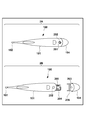
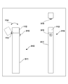
- FIG. 1 is a diagram showing an external configuration when the electronic thermometer 100 and its storage case 110 are viewed from the front and side.
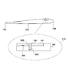
- FIG. 2 is a view showing a method for attaching and removing the tail housing 104 of the electronic thermometer 100.
- FIG. 3 is a view showing a structure for fixing the tail housing 104 of the electronic thermometer 100.
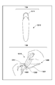
- FIG. 4 is a view for explaining a method of fixing and releasing the tail housing 104 by the storage case 110.
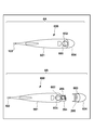
- FIG. 5 is a diagram illustrating an external configuration when viewed from the front, side, and top surface of the storage case 510.
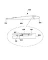
- FIG. 6 is a diagram illustrating a method for attaching and detaching the tail housing 604 of the electronic thermometer 600.
- FIG. 7 is a view showing a structure for fixing the tail housing 604 of the electronic thermometer 600.
- FIG. 8 is a view for explaining a method of fixing and releasing the tail housing 604 by the storage case 510.
- FIG. 9 is a diagram showing an external configuration when viewed from the front, side, and top surface of the storage case 910.
- FIG. 10 is a diagram illustrating a method for attaching and detaching the tail housing 1004 of the electronic thermometer 1000.
- FIG. 11 is a diagram showing a structure for fixing the tail housing 1004 of the electronic thermometer 1000.
- FIG. 12 is a view for explaining a method of releasing the fixation of the tail housing 1004 by the storage case 910.
- FIG. 13 is a diagram showing how the battery housing 1302 of the electronic thermometer 1300 is attached or removed.
- FIG. 1 is a diagram showing an external configuration when the electronic thermometer 100 and the storage case 110 according to the first embodiment of the present invention that stores the electronic thermometer 100 are viewed from the front and side.
- 101 is a main body housing of the electronic thermometer 100, and 102 is an end cap.
- the end cap 102 is covered with a metal such as stainless steel so that the body temperature of the subject can be easily conducted to the built-in temperature measurement unit.
- Reference numeral 103 denotes a display unit that displays body temperature data and the like as body temperature measurement results.
- Reference numeral 104 denotes a tail housing, which is detachably attached to the main body housing 101.
- thermometer 100 is configured such that the built-in battery is exposed to the outside by removing the tail housing 104 from the main body housing 101, thereby allowing the user to replace the battery as necessary. Can do.
- 111 is a main body of the storage case 110, and 112 is a lid that covers the top of the main body 111.
- the lid portion 112 is connected to the main body portion 111 via the rotation portion 113, and thereby the lid portion 112 rotates in the direction of the arrow 114.
- a screwing jig 115 (in this embodiment, a hexagon wrench) is attached near the upper end of the side surface of the main body 111 in the major axis direction, and the user uses the screwing jig 115 attached to the main body 111.
- a screwing member for fixing the tail housing 104 to the main body housing 101 (in this embodiment, a hexagonal screw; details will be described later) can be tightened or loosened.
- FIG. 2 is a view for explaining a method for attaching and removing the tail housing 104 of the electronic thermometer 100.
- 2A in FIG. 2 shows an external configuration when the state where the tail housing 104 is attached is viewed from the back side of the electronic thermometer 100.
- a screw member 201 and a screw member 201 are attached to the tail housing 104 attached to the main body housing 101 in order to fix the tail housing 104 to the main body housing 101.
- a through-hole 202 for penetrating them.
- 2B shows a state in which the tail housing 104 is removed from the main body housing 101 after the screwing member 201 is removed.
- the tail housing 104 is provided with a screwing hole 203 into which the screwing member 201 is screwed.
- the screw hole 203 is provided at a position that matches the through hole 202 when the tail housing 104 is attached to the main body housing 101.
- the tail housing 104 is provided with a packing 206 for maintaining liquid tightness in the main body housing 101.
- the packing 206 is disposed so that the position when the tail housing 104 is attached to the main body housing 101 is closer to the front end side than the through hole 202 in order to prevent liquid from entering from the through hole 202.
- the tail side of the main body housing 101 is a state in which a region (battery portion) in which the battery 205 is mounted is exposed to the outside of the circuit board 204. It becomes. As a result, the user can easily replace the battery 205.
- FIG. 3 is a view showing a structure for fixing the tail housing 104 of the electronic thermometer 100.
- the tail housing 104 when the tail housing 104 is attached to the main body housing 101, the positions of the through holes 202 and the screw holes 203 coincide with each other. It can be screwed into the screw hole 203 of the tail housing 104 through the through hole 202. Thus, the main body housing 101 and the tail housing 104 are firmly fixed to each other by being screwed by the screwing member 201.
- FIG. 4 is a view for explaining a method of fixing and releasing the tail housing 104.
- the electronic thermometer 100 uses a storage case 110 to fix and release the tail housing 104.
- FIG. 4A shows an insertion groove (this embodiment) in which a screwing jig 115 (in this embodiment, a hex wrench) of the storage case 110 is provided on the head of a screwing member 201 (in this embodiment, a hex screw). Shows a state of being inserted into a hexagonal groove.
- tip of the screwing jig 115 can be inserted in the insertion groove of the head of the screwing member 201 by moving the side surface of the storage case 110 to the arrow 401 direction.
- FIG. 4B of FIG. 4 shows a state in which the operation of tightening (or loosening) the screwing member 201 using the storage case 110 is performed.
- the bottom side of the storage case 110 is rotated in the direction of the arrow 402 in a state where the tip of the screwing jig 115 is inserted into the insertion groove of the head of the screwing member 201.
- the screwing member 201 can be tightened or loosened (that is, the screwing member 201 can be operated between a fixed position and an unfixed position).
- the screwing jig 115 is disposed near the upper end of the side surface of the storage case 110 in the major axis direction, the screwing jig 115 is inserted into the insertion groove on the head of the screwing member 201.
- the distance L from the rotation center of the storage case 110 to the operation position can be increased. That is, the user can tighten or loosen the screwing member 201 with a small force.
- the screwing jig is arranged near the upper end of the side surface of the storage case 110 in the long axis direction.
- the screw for fixing the main body housing 101 and the tail housing 104 can be used by using the screwing jig disposed in the storage case 110.
- the joint member 201 can be easily tightened or loosened. That is, battery replacement can be easily performed.
- a hexagonal screw is used as an example of the screwing member 201.
- the type of screw is not limited to this, and any head shape or shape and size of the insertion groove can be applied. Needless to say.
- a screw member such as a screw is used as a fixing member for fixing the main body housing 101 and the tail housing 104, but the present invention is not limited to this.
- the main body housing 101 and the tail housing 104 may be fixed by using a fitting member that is fitted into a fitting groove provided in the tail housing 104. Details of this embodiment will be described below.
- FIG. 5 is a diagram showing an external configuration when a storage case 510 according to the second embodiment of the present invention that stores an electronic thermometer is viewed from the front, side, and top.
- reference numeral 511 denotes a main body of the storage case 510
- reference numeral 112 denotes a lid that covers the upper portion of the main body 511.
- the lid portion 112 is connected to the main body portion 511 via the rotation portion 113, and thereby the lid portion 112 rotates in the direction of the arrow 114.
- a semi-circular fitting jig 515 is attached to the vicinity of the upper end of the side surface of the main body 511 in the major axis direction, and the user uses the fitting jig 515 attached to the main body 511 to remove the tail housing.
- a fitting member (details will be described later) that is a fixing member for fixing to the main body housing can be operated between a fitting position (fixed position) and a non-fitted position (non-fixed position).
- FIG. 6 is a view for explaining how to attach and remove the tail housing of the electronic thermometer.
- 6A in FIG. 6 shows an external configuration when the state where the tail housing 604 is attached is viewed from the back side of the electronic thermometer 600.
- the tail housing 604 attached to the main body housing 601 is fitted to the main body housing 601, and the fitting member 605 and the fitting member 605 are fixed.
- a through-hole 602 for penetrating the substrate is provided.
- 6B in FIG. 6 shows a state where the tail housing 604 is removed from the main body housing 601 after the fitting member 605 is rotated to the non-fitting position.
- the tail housing 604 is provided with a fitting groove 603 into which the fitting member 605 is fitted.
- the fitting groove 603 is disposed so as to be positioned closer to the distal end side than the fitting member 605, and when the fitting member 605 is fitted, the tail portion The operation in the removing direction of the housing 604 is restricted.
- the battery 205 of the circuit board 204 is mounted on the tail side of the main body housing 601.
- the formed area (battery part) is exposed to the outside. As a result, the user can easily replace the battery 205.
- FIG. 7 is a view showing a structure for fixing the tail housing 604 of the electronic thermometer 600.
- the fitting member 605 passes through the through hole 602 provided on the back surface side of the main body housing 601, and after the tail housing 604 is attached to the main body housing 601, the fitting member 605. Is turned, the tip of the fitting member 605 is fitted into the fitting groove 603 of the tail housing 604. Thereby, the operation
- FIG. 8 is a view for explaining a method of fixing and releasing the tail housing 604.
- the electronic thermometer 600 uses a storage case 510 for fixing and releasing the tail housing 604.
- FIG. 8A shows a state in which the fitting jig 515 of the storage case 510 is inserted into the insertion groove provided in the head of the fitting member 605.
- FIG. 8A of FIG. 8 the side of the storage case 510 is moved in the direction of the arrow 801, so that the tip of the fitting jig 515 is inserted into the insertion groove (in this embodiment, a linear shape in the head). Groove).
- FIG. 8B in FIG. 8 shows a state in which the fitting member 605 is operated between the fitting position and the non-fitting position using the storage case 510.
- the bottom surface side of the storage case 510 is rotated in the direction of the arrow 802 in a state where the tip of the fitting jig 515 is inserted into the insertion groove of the head of the fitting member 605.
- the fitting member 605 can be operated between the fitting position and the non-fitting position.
- the fitting jig 515 is disposed in the vicinity of the upper end of the side surface of the storage case 510 in the major axis direction, the fitting jig 515 is inserted into the insertion groove on the head of the fitting member 605.
- the distance L from the rotation center of the storage case 510 to the operation position can be increased. That is, the user can operate the fitting member 605 between the fitting position and the non-fitting position with a small force.
- the fitting jig is arranged near the upper end of the side surface of the storage case 510 in the long axis direction.
- the user does not prepare a predetermined tool every time the battery is replaced, but by using the fitting jig disposed in the storage case 510, the fitting for fixing the main body housing 601 and the tail housing 604 can be performed.
- the joint member 605 can be easily operated. That is, battery replacement can be easily performed.
- a linear groove is used as the insertion groove at the head of the fitting member 605.
- the shape of the insertion groove is not limited to this.
- the position and shape of the fitting groove 603 into which the fitting member 605 is fitted are not limited to the position and shape described in the present embodiment.
- the fitting member is provided on the main body housing side, the fitting groove is provided on the tail housing side, and the fitting member is fitted in the fitting groove, whereby the operation in the removing direction of the tail housing is performed.
- the configuration is restricted, the present invention is not limited to this.
- the locking member may be provided on the tail housing side, and the locking hole for locking the locking member on the main body housing side may be provided. Details of this embodiment will be described below.
- FIG. 9 is a diagram showing an external configuration when a storage case 910 according to the third embodiment of the present invention that stores an electronic thermometer is viewed from the front, side, and top.
- reference numeral 911 denotes a main body portion of the storage case 910
- reference numeral 112 denotes a lid portion that covers the upper portion of the main body portion 911.
- the lid portion 112 is connected to the main body portion 911 via the rotation portion 113, and thereby the lid portion 112 rotates in the direction of the arrow 114.
- a locking jig 915 having a cross-shaped cross section is attached to the vicinity of the upper end in the major axis direction of the side surface of the main body 911, and the user uses the locking jig 915 attached to the main body 911,
- a locking member (details will be described later), which is a fixing member for fixing the tail housing to the main body housing, can be moved to the non-locking position.
- FIG. 10 is a view for explaining a method of attaching and removing the tail housing 1004 of the electronic thermometer.
- 10A in FIG. 10 is a diagram showing an external configuration when the state where the tail housing 1004 is attached is viewed from the back side of the electronic thermometer 1000.
- the main body housing 1001 is inserted when the locking member provided on the tail housing 1004 is moved to the non-locking position in order to fix the tail housing 1004 to the main body housing 1001.
- a cross-shaped operation hole 1005 is provided. Note that a locking hole for locking the locking member is further provided on the back surface of the operation hole 1005, and the operation hole 1005 communicates with the locking hole.
- FIG. 10B in FIG. 10 shows a state in which the tail housing 1004 is detached from the main body housing 1001 after the locking member is moved to the non-locking position.
- the tail housing 1004 is provided with a locking member 1003.
- the locking member 1003 is disposed so as to come to the position of the locking hole provided on the back surface of the operation hole 1005. The movement of the tail housing 1004 in the removal direction is restricted by being locked by.
- the tail side of the main body housing 1001 is a state in which the region (battery portion) in which the battery 205 is mounted is exposed to the outside of the circuit board 204. It becomes. As a result, the user can easily replace the battery 205.
- FIG. 11 is a diagram showing a structure for fixing the tail housing 1004 of the electronic thermometer 1000.
- the locking member 1003 is biased toward the upper side of the paper (the back side of the electronic thermometer 1000) by an elastic member 1101 such as a spring. Therefore, in a state where the tail housing 1004 is attached to the main body housing 1001 (that is, a state where the position of the locking member 1003 and the position of the locking hole 1102 match), the locking member 1003 is in the locked position (fixed). To the position) and is locked by the locking hole 1102. Thereby, the operation
- the locking jig 915 is inserted into the operation hole 1005, and the tip of the locking jig 915 is attached.
- the locking member 1003 is pressed against the urging direction, the locking member 1003 moves to the non-locking position (non-fixed position).
- the tail housing 1004 is movable in the removal direction.
- FIG. 12 is a view for explaining a method of releasing the fixation of the tail housing 1004.
- the electronic thermometer 1000 uses a storage case 910 for releasing the fixation of the tail housing 1004.
- FIG. 12 shows a state where the locking jig 915 of the storage case 910 is inserted into the operation hole 1005.
- the locking jig 915 and the operation hole 1005 of the storage case 910 have cross shapes, respectively, and are moved in the direction of the arrow 1201 in a state in which the directions are matched with each other.
- the tip of the locking jig 915 is inserted into the operation hole 1005.
- the locking jig 915 With the distal end of the locking jig 915 inserted into the operation hole 1005, the locking jig 915 is further moved in the direction of the arrow 1201, and the locking member 1003 is pressed, so that the locking member 1003 is in the non-locking position. (That is, the tail housing 1004 is released). As a result, the tail housing 1004 can be removed.
- the latching jig 915 is arranged in the storage case 910.
- the user can easily release the fixing of the tail housing 1004 by using the locking jig disposed in the storage case 910 without preparing a predetermined tool each time the battery is replaced. It becomes possible. That is, battery replacement can be easily performed.
- the cross shape is used as the shape of the operation hole 1005.
- the shape of the operation hole 1005 is not limited to this, and any shape conforming to the cross-sectional shape of the locking jig 915 can be used. Needless to say, it may be formed in any shape.
- the material of the storage case is not particularly mentioned, but it may be made of a transparent or translucent material, for example. This is because, by using a transparent or translucent material, the position of the jig can be visually recognized when the tail housing is unfixed, so that the jig can be easily positioned. In addition, in order to make positioning of a jig easy, you may make it provide a marker in a storage case.
- the screwing jig and the screwing member may be made of a magnetic material.
- the screwing jig and the screwing member may be made of a magnetic material.
- a fixing member for fixing the tail housing 104 is separately provided.
- the present invention is not limited to this.
- the battery housing itself is screwed or fitted. It may have a function as a joint member.
- FIG. 13 shows how the battery housing 1302 of the electronic thermometer 1300 is attached or removed.
- the electronic thermometer 1300 is equipped with the battery housing 1302 for covering the built-in battery on the back side of the main body housing 1301, and the built-in electronic thermometer 1300 is removed by removing the battery housing 1302. The battery is exposed to the outside. Thereby, the user can perform battery replacement as needed.
- a screwing groove (not shown) is provided in the outer peripheral portion of the battery housing 1302, and the battery housing 1302 is fixed to the main body housing 1301 by being screwed into a screwing hole provided in the main body housing 1301. Will be.
- FIG. 13A is a view showing an external configuration of a storage case 1310 having a screwing jig 1311 for tightening or loosening the battery housing 1302 in order to fix the battery housing 1302 to the main body housing 1301.
- the screwing jig 1311 is provided at the end of the storage case 1310 in the long axis direction, and is an insertion groove (in this embodiment, a linear shape) provided on the surface of the battery housing 1302.
- the groove can be inserted into the groove 1303.
- the battery housing 1302 is tightened or loosened by rotating the storage case 1310 in a state where the screwing jig 1311 is inserted into the insertion groove 1303 of the battery housing 1302. It becomes possible.
Landscapes
- Physics & Mathematics (AREA)
- General Physics & Mathematics (AREA)
- Casings For Electric Apparatus (AREA)
Description
本発明は、電子体温計の収納ケースに関するものである。
被検体の体温を測定するための体温計として、現在、電子体温計が広く普及している。電子体温計には、通常、温度センサと、当該温度センサにより検出された温度に基づいて、被検体の体温を算出する回路基板と、当該回路基板に電源を供給する電池とが搭載されている。
このうち、電池は消耗品であるため、必要に応じてユーザが交換できるよう、着脱可能に取り付けられている。具体的には、ハウジングの一部(電池蓋)を取り外すことで、電池が搭載された領域が露出されるように構成されており、これにより、ユーザは、使用済みの電池を簡単に交換することができる。
一方で、上述のような電池交換が可能な電子体温計の場合、電池蓋が簡単に外せる構造となっていたのでは、測定中に電池が脱落したり、幼児等が電池を誤飲してしまうといった恐れがある。
このため、電池蓋は、所定の工具(例えば、ドライバ等)を使用して、ねじ等の螺合部材を用いて固定される構造となっていることが望ましい。
しかしながら、電池交換のたびに、ユーザが電池蓋の螺合部材に適合する工具を準備しなければならないとすると、ユーザにとっては著しく利便性が損なわれることとなる。
このようなことから、電子体温計においては、電池蓋が簡単に外れにくい構造を備えつつ、かつ、電池交換が容易に行える構成であることが望ましい。
本発明は上記課題に鑑みてなされてものであり、電池の交換作業を容易に行うことができる電子体温計を提供することを目的とする。
上記の目的を達成するために本発明に係る電子体温計の収納ケースは以下のような構成を備える。即ち、
被検者の体温を測定する電子体温計を収納する収納ケースであって、
前記電子体温計は、内蔵された電池部分を覆う第1のハウジングと、該電池部分とは異なる領域を覆う第2のハウジングとを有しており、
前記収納ケースは、
前記第1のハウジングと前記第2のハウジングとを固定するための固定部材を、固定位置と非固定位置との間で動作させるための冶具を有しており、
前記冶具は、
前記固定部材の頭部の形状または頭部に設けられた溝の形状、あるいは、前記固定部材を動作させる際に挿入される前記第2のハウジングの孔の形状に適合した断面形状を有していることを特徴とする。
被検者の体温を測定する電子体温計を収納する収納ケースであって、
前記電子体温計は、内蔵された電池部分を覆う第1のハウジングと、該電池部分とは異なる領域を覆う第2のハウジングとを有しており、
前記収納ケースは、
前記第1のハウジングと前記第2のハウジングとを固定するための固定部材を、固定位置と非固定位置との間で動作させるための冶具を有しており、
前記冶具は、
前記固定部材の頭部の形状または頭部に設けられた溝の形状、あるいは、前記固定部材を動作させる際に挿入される前記第2のハウジングの孔の形状に適合した断面形状を有していることを特徴とする。
本発明によれば、電池交換を容易に行うことができる電子体温計を提供することが可能となる。
本発明のその他の特徴及び利点は、添付図面を参照とした以下の説明により明らかになるであろう。なお、添付図面においては、同じ若しくは同様の構成には、同じ参照番号を付す。
添付図面は明細書に含まれ、その一部を構成し、本発明の実施の形態を示し、その記述と共に本発明の原理を説明するために用いられる。
図1は、電子体温計100及びその収納ケース110を正面及び側面から見た場合の外観構成を示す図である。
図2は、電子体温計100の尾部ハウジング104の取り付け及び取り外し方法を示す図である。
図3は、電子体温計100の尾部ハウジング104を固定するための構造を示す図である。
図4は、収納ケース110による、尾部ハウジング104の固定及び解除の方法を説明するための図である。
図5は、収納ケース510の正面、側面及び上面から見た場合の外観構成を示す図である。
図6は、電子体温計600の尾部ハウジング604の取り付け及び取り外し方法を示す図である。
図7は、電子体温計600の尾部ハウジング604を固定するための構造を示す図である。
図8は、収納ケース510による、尾部ハウジング604の固定及び解除の方法を説明するための図である。
図9は、収納ケース910の正面、側面及び上面から見た場合の外観構成を示す図である。
図10は、電子体温計1000の尾部ハウジング1004の取り付け及び取り外し方法を示す図である。
図11は、電子体温計1000の尾部ハウジング1004を固定するための構造を示す図である。
図12は、収納ケース910による、尾部ハウジング1004の固定解除の方法を説明するための図である。
図13は、電子体温計1300の電池ハウジング1302を取り付けまたは取り外す様子を示した図である。
以下、必要に応じて添付図面を参照しながら本発明の各実施形態の詳細を説明する。なお、以下に述べる実施の形態は、本発明の好適な具体例であるから、技術的に好ましい種々の限定が付されているが、本発明の範囲は、以下の説明において特に本発明を限定する旨の記載がない限り、これらの態様に限られるものではない。
[第1の実施形態]
<1.電子体温計及び収納ケースの外観構成>
図1は、電子体温計100及び電子体温計100を収納する、本発明の第1の実施形態に係る収納ケース110を正面及び側面から見た場合の外観構成を示す図である。
<1.電子体温計及び収納ケースの外観構成>
図1は、電子体温計100及び電子体温計100を収納する、本発明の第1の実施形態に係る収納ケース110を正面及び側面から見た場合の外観構成を示す図である。
図1において、101は電子体温計100の本体ハウジングであり、102はエンドキャップである。エンドキャップ102は、内蔵された温度計測部に対して被検者の体温が伝導しやすいように、ステンレスなどの金属により被覆されている。103は体温測定結果として体温データ等を表示する表示部である。104は尾部ハウジングであり、本体ハウジング101に対して着脱可能に取り付けられている。
なお、電子体温計100では、尾部ハウジング104が本体ハウジング101から取り外されることにより、内蔵された電池が外部に露出するよう構成されており、これにより、ユーザは、必要に応じて電池交換を行うことができる。
111は収納ケース110の本体部であり、112は本体部111の上部を覆う蓋部である。蓋部112は回動部113を介して本体部111に接続されており、これにより、蓋部112は矢印114方向に回動する。
本体部111の側面の長軸方向の上端付近には、螺合冶具115(本実施形態では六角レンチ)が取り付けられており、ユーザは本体部111に取り付けられた螺合冶具115を用いることにより、尾部ハウジング104を本体ハウジング101に固定するための螺合部材(本実施形態では六角ねじ。詳細は後述)を締めたり、緩めたりすることができる。
<2.尾部ハウジングの取り付け及び取り外し>
次に、電子体温計100の尾部ハウジング104の取り付け及び取り外し方法について説明する。図2は、電子体温計100の尾部ハウジング104の取り付け及び取り外し方法を説明するための図である。
次に、電子体温計100の尾部ハウジング104の取り付け及び取り外し方法について説明する。図2は、電子体温計100の尾部ハウジング104の取り付け及び取り外し方法を説明するための図である。
このうち、図2の2Aは、尾部ハウジング104が取り付けられた状態を、電子体温計100の裏面側から見た場合の外観構成を示している。図2の2Aに示すように、電子体温計100の裏面側には、本体ハウジング101に取り付けられた尾部ハウジング104を、本体ハウジング101に固定するために、螺合部材201と、該螺合部材201を貫通させるための貫通孔202とが設けられている。
図2の2Bは、螺合部材201を取り外した後、尾部ハウジング104を本体ハウジング101から取り外した様子を示している。図2の2Bに示すように、尾部ハウジング104には、螺合部材201が螺合される螺合孔203が設けられている。螺合孔203は、尾部ハウジング104を本体ハウジング101に取り付けた際に、貫通孔202と合致する位置に設けられている。また、尾部ハウジング104には、本体ハウジング101内の液密性を保つためのパッキン206が設けられている。パッキン206は、貫通孔202からの液体の浸入を防ぐために、尾部ハウジング104を本体ハウジング101に取り付けた際の位置が、貫通孔202よりも先端側にくるように配置されている。
更に、図2の2Bに示すように、尾部ハウジング104が取り外されると、本体ハウジング101の尾部側は、回路基板204のうち、電池205が搭載された領域(電池部分)が外部に露出した状態となる。これにより、ユーザは、電池205を容易に交換することができる。
<3.尾部ハウジングを固定するための構造>
次に、電子体温計100の尾部ハウジング104を本体ハウジング101に固定するための構造について、図3を用いて詳説する。図3は、電子体温計100の尾部ハウジング104を固定するための構造を示す図である。
次に、電子体温計100の尾部ハウジング104を本体ハウジング101に固定するための構造について、図3を用いて詳説する。図3は、電子体温計100の尾部ハウジング104を固定するための構造を示す図である。
図3に示すように、尾部ハウジング104が本体ハウジング101に取り付けられた状態では、貫通孔202と螺合孔203の位置とは互いに一致しているため、螺合部材201は、本体ハウジング101の貫通孔202を介して、尾部ハウジング104の螺合孔203に螺合することができる。このように螺合部材201により螺合されることにより、本体ハウジング101と尾部ハウジング104とは、互いに強固に固定されることとなる。
<4.尾部ハウジングの固定及び解除の方法>
次に、尾部ハウジング104の固定及び解除の方法について説明する。図4は、尾部ハウジング104の固定及び解除の方法を説明するための図である。
次に、尾部ハウジング104の固定及び解除の方法について説明する。図4は、尾部ハウジング104の固定及び解除の方法を説明するための図である。
図4に示すように、電子体温計100では、尾部ハウジング104の固定及び解除を行うにあたり、収納ケース110を利用する。
図4の4Aは、収納ケース110の螺合冶具115(本実施形態では、六角レンチ)を螺合部材201(本実施形態では、六角ねじ)の頭部に設けられた挿入溝(本実施形態では、六角溝)に挿入させる様子を示している。図4の4Aに示すように、収納ケース110の側面を矢印401方向に移動させることで、螺合冶具115の先端を、螺合部材201の頭部の挿入溝に挿入させることができる。
図4の4Bは、収納ケース110を用いて、螺合部材201を締める(または緩める)動作を行った様子を示している。
図4の4Bに示すように、螺合冶具115の先端が、螺合部材201の頭部の挿入溝に挿入された状態で、収納ケース110の底面側を矢印402方向に回動させることで、螺合部材201を締めたり、緩めたりすることができる(つまり、螺合部材201を固定位置と非固定位置との間で動作させることができる)。
上述したように、螺合冶具115は、収納ケース110の側面の長軸方向の上端付近に配置されているため、螺合冶具115が螺合部材201の頭部の挿入溝に挿入された状態で、収納ケース110の底面側を操作した場合、収納ケース110の回動中心から操作位置までの距離Lを大きくとることができる。つまり、ユーザは、少ない力で、螺合部材201を締めたり緩めたりすることができる。
以上の説明から明らかなように、本実施形態では、収納ケース110の側面の長軸方向の上端付近に螺合冶具を配する構成とした。
これにより、ユーザは、電池交換のたびに所定の工具を準備しなくても、収納ケース110に配された螺合冶具を用いることで、本体ハウジング101と尾部ハウジング104とを固定するための螺合部材201を、容易に、締めたり緩めたりすることが可能となる。つまり、電池交換を容易に行うことができるようになる。
なお、本実施形態では、螺合部材201の一例として六角ねじを挙げたが、ねじの種類はこれに限定されず、頭部形状や挿入溝の形状及び大きさとして任意のものが適用可能であることはいうまでもない。
[第2の実施形態]
上記第1の実施形態では、本体ハウジング101と尾部ハウジング104とを固定するための固定部材として、ねじ等の螺合部材を用いる構成としたが、本発明はこれに限定されない。例えば、尾部ハウジング104に設けられた嵌合溝に嵌合させる嵌合部材を用いることにより、本体ハウジング101と尾部ハウジング104とを固定する構成としてもよい。以下、本実施形態の詳細について説明する。
上記第1の実施形態では、本体ハウジング101と尾部ハウジング104とを固定するための固定部材として、ねじ等の螺合部材を用いる構成としたが、本発明はこれに限定されない。例えば、尾部ハウジング104に設けられた嵌合溝に嵌合させる嵌合部材を用いることにより、本体ハウジング101と尾部ハウジング104とを固定する構成としてもよい。以下、本実施形態の詳細について説明する。
<1.収納ケースの外観構成>
図5は、電子体温計を収納する、本発明の第2の実施形態に係る収納ケース510を正面、側面、及び上面から見た場合の外観構成を示す図である。
図5は、電子体温計を収納する、本発明の第2の実施形態に係る収納ケース510を正面、側面、及び上面から見た場合の外観構成を示す図である。
図5において、511は収納ケース510の本体部であり、112は本体部511の上部を覆う蓋部である。蓋部112は回動部113を介して本体部511に接続されており、これにより、蓋部112は矢印114方向に回動する。
本体部511の側面の長軸方向の上端付近には、半円形の嵌合冶具515が取り付けられており、ユーザは本体部511に取り付けられた当該嵌合冶具515を用いることにより、尾部ハウジングを本体ハウジングに固定するための固定部材である嵌合部材(詳細は後述)を、嵌合位置(固定位置)と非嵌合位置(非固定位置)との間で動作させることができる。
<2.尾部ハウジングの取り付け及び取り外し>
次に、電子体温計の尾部ハウジングの取り付け及び取り外し方法について説明する。図6は、電子体温計の尾部ハウジングの取り付け及び取り外し方法を説明するための図である。
次に、電子体温計の尾部ハウジングの取り付け及び取り外し方法について説明する。図6は、電子体温計の尾部ハウジングの取り付け及び取り外し方法を説明するための図である。
このうち、図6の6Aは、尾部ハウジング604が取り付けられた状態を、電子体温計600の裏面側から見た場合の外観構成を示している。図6の6Aに示すように、電子体温計600の裏面側には、本体ハウジング601に取り付けられた尾部ハウジング604を、本体ハウジング601に固定するために、嵌合部材605と、該嵌合部材605を貫通させるための貫通孔602とが設けられている。
図6の6Bは、嵌合部材605を非嵌合位置まで回動させた後、尾部ハウジング604を本体ハウジング601から取り外した様子を示している。図6の6Bに示すように、尾部ハウジング604には、嵌合部材605が嵌合される嵌合溝603が設けられている。嵌合溝603は、尾部ハウジング604を本体ハウジング601に取り付けた際に、嵌合部材605よりも先端側に位置するように配置されており、嵌合部材605が嵌合されることにより、尾部ハウジング604の取り外し方向の動作が規制される。
なお、図6の6Bに示すように、嵌合部材605が非嵌合位置まで回動され尾部ハウジング604が取り外されると、本体ハウジング601の尾部側は、回路基板204のうち、電池205が搭載された領域(電池部分)が外部に露出した状態となる。これにより、ユーザは、電池205を容易に交換することができる。
<3.尾部ハウジングを固定するための構造>
次に、電子体温計600の尾部ハウジング604を本体ハウジング601に固定するための構造について、図7を用いて詳説する。図7は、電子体温計600の尾部ハウジング604を固定するための構造を示す図である。
次に、電子体温計600の尾部ハウジング604を本体ハウジング601に固定するための構造について、図7を用いて詳説する。図7は、電子体温計600の尾部ハウジング604を固定するための構造を示す図である。
図7に示すように、本体ハウジング601の裏面側に設けられた貫通孔602には、嵌合部材605が貫通しており、尾部ハウジング604が本体ハウジング601に取り付けられた後に、嵌合部材605が回動されることにより、嵌合部材605の先端は、尾部ハウジング604の嵌合溝603に嵌合されることとなる。これにより、尾部ハウジング604の取り外し方向の動作が規制され、本体ハウジング601と尾部ハウジング604とは、互いに強固に固定されることとなる。
<4.尾部ハウジングの固定及び解除の方法>
次に、尾部ハウジング604の固定及び解除の方法について説明する。図8は、尾部ハウジング604の固定及び解除の方法を説明するための図である。
次に、尾部ハウジング604の固定及び解除の方法について説明する。図8は、尾部ハウジング604の固定及び解除の方法を説明するための図である。
図8に示すように、電子体温計600では、尾部ハウジング604の固定及び解除を行うにあたり、収納ケース510を利用する。
図8の8Aは、収納ケース510の嵌合冶具515を嵌合部材605の頭部に設けられた挿入溝に挿入させる様子を示している。図8の8Aに示すように、収納ケース510の側面を矢印801方向に移動させることで、嵌合冶具515の先端を、嵌合部材605の頭部の挿入溝(本実施形態では直線状の溝)に挿入させることができる。
図8の8Bは、収納ケース510を用いて、嵌合部材605を嵌合位置と非嵌合位置との間で動作させた様子を示している。
図8の8Bに示すように、嵌合冶具515の先端が、嵌合部材605の頭部の挿入溝に挿入された状態で、収納ケース510の底面側を矢印802方向に回動させることで、嵌合部材605を嵌合位置と非嵌合位置との間で動作させることができる。
上述したように、嵌合冶具515は、収納ケース510の側面の長軸方向の上端付近に配置されているため、嵌合冶具515が嵌合部材605の頭部の挿入溝に挿入された状態で、収納ケース510の底面側を操作した場合、収納ケース510の回動中心から操作位置までの距離Lを大きくとることができる。つまり、ユーザは、少ない力で、嵌合部材605を、嵌合位置と非嵌合位置との間で動作させることができる。
以上の説明から明らかなように、本実施形態では、収納ケース510の側面の長軸方向の上端付近に嵌合冶具を配する構成とした。
これにより、ユーザは、電池交換のたびに所定の工具を準備しなくても、収納ケース510に配された嵌合冶具を用いることで、本体ハウジング601と尾部ハウジング604とを固定するための嵌合部材605を、容易に、動作させることが可能となる。つまり、電池交換を容易に行うことができるようになる。
なお、本実施形態では、嵌合部材605の頭部の挿入溝として、直線状の溝を挙げたが、挿入溝の形状はこれに限定されるものではない。同様に、嵌合部材605が嵌合される嵌合溝603の位置及び形状も、本実施形態において説明した位置及び形状に限定されるものではない。
[第3の実施形態]
上記第2の実施形態では、嵌合部材を本体ハウジング側に、嵌合溝を尾部ハウジング側にそれぞれ設け、嵌合部材を嵌合溝に嵌合させることで、尾部ハウジングの取り外し方向の動作を規制する構成としたが、本発明はこれに限定されない。例えば、係止部材を尾部ハウジング側に設け、本体ハウジング側に当該係止部材を係止させるための係止孔を設ける構成としてもよい。以下、本実施形態の詳細について説明する。
上記第2の実施形態では、嵌合部材を本体ハウジング側に、嵌合溝を尾部ハウジング側にそれぞれ設け、嵌合部材を嵌合溝に嵌合させることで、尾部ハウジングの取り外し方向の動作を規制する構成としたが、本発明はこれに限定されない。例えば、係止部材を尾部ハウジング側に設け、本体ハウジング側に当該係止部材を係止させるための係止孔を設ける構成としてもよい。以下、本実施形態の詳細について説明する。
<1.収納ケースの外観構成>
図9は、電子体温計を収納する、本発明の第3の実施形態に係る収納ケース910を正面、側面、及び上面から見た場合の外観構成を示す図である。
図9は、電子体温計を収納する、本発明の第3の実施形態に係る収納ケース910を正面、側面、及び上面から見た場合の外観構成を示す図である。
図9において、911は収納ケース910の本体部であり、112は本体部911の上部を覆う蓋部である。蓋部112は回動部113を介して本体部911に接続されており、これにより、蓋部112は矢印114方向に回動する。
本体部911の側面の長軸方向の上端付近には、断面形状が十字型の係止冶具915が取り付けられており、ユーザは本体部911に取り付けられた当該係止冶具915を用いることにより、尾部ハウジングを本体ハウジングに固定するための固定部材である係止部材(詳細は後述)を、非係止位置に移動させることができる。
<2.尾部ハウジングの取り付け及び取り外し>
次に、電子体温計の尾部ハウジングの取り付け及び取り外し方法について説明する。図10は、電子体温計の尾部ハウジング1004の取り付け及び取り外し方法を説明するための図である。
次に、電子体温計の尾部ハウジングの取り付け及び取り外し方法について説明する。図10は、電子体温計の尾部ハウジング1004の取り付け及び取り外し方法を説明するための図である。
このうち、図10の10Aは、尾部ハウジング1004が取り付けられた状態を、電子体温計1000の裏面側から見た場合の外観構成を示す図である。図10の10Aに示すように、本体ハウジング1001には、尾部ハウジング1004を本体ハウジング1001に固定させるべく尾部ハウジング1004に設けられた係止部材を、非係止位置に移動させる際に挿入される十字型の操作孔1005が設けられている。なお、操作孔1005の背面には、更に、係止部材を係止させるための係止孔が配されており、操作孔1005は当該係止孔に連通している。
図10の10Bは、係止部材を非係止位置まで移動させた後、尾部ハウジング1004を本体ハウジング1001から取り外した様子を示している。図10の10Bに示すように、尾部ハウジング1004には、係止部材1003が設けられている。係止部材1003は、尾部ハウジング1004を本体ハウジング1001に取り付けた際に、操作孔1005の背面に設けられた係止孔の位置にくるように配置されており、係止部材1003が係止孔により係止されることで、尾部ハウジング1004の取り外し方向の動作が規制される。
なお、図10の10Bに示すように、尾部ハウジング1004が取り外されると、本体ハウジング1001の尾部側は、回路基板204のうち、電池205が搭載された領域(電池部分)が外部に露出した状態となる。これにより、ユーザは、電池205を容易に交換することができる。
<3.尾部ハウジングを固定するための構造>
次に、電子体温計1000の尾部ハウジング1004を本体ハウジング1001に固定するための構造について、図11を用いて詳説する。図11は、電子体温計1000の尾部ハウジング1004を固定するための構造を示す図である。
次に、電子体温計1000の尾部ハウジング1004を本体ハウジング1001に固定するための構造について、図11を用いて詳説する。図11は、電子体温計1000の尾部ハウジング1004を固定するための構造を示す図である。
図11の拡大表示1100に示すように、係止部材1003は、ばね等の弾性部材1101により紙面上側(電子体温計1000の裏面側)に向かって付勢されている。このため、尾部ハウジング1004が本体ハウジング1001に取り付けられた状態(つまり、係止部材1003の位置と係止孔1102の位置とが一致した状態)では、係止部材1003は、係止位置(固定位置)まで移動し、係止孔1102によって係止される。これにより、尾部ハウジング1004の取り外し方向の動作が規制され、本体ハウジング1001と尾部ハウジング1004とは、互いに強固に固定されることとなる。
一方、図11の拡大表示1110に示すように、係止部材1003が係止孔1102に係止された状態で、係止冶具915を操作孔1005に挿入し、係止冶具915の先端が付勢方向に反して係止部材1003を押圧すると、係止部材1003は、非係止位置(非固定位置)まで移動する。これにより、尾部ハウジング1004は取り外し方向に移動可能な状態となる。
<4.尾部ハウジングの固定解除の方法>
次に、尾部ハウジング1004の固定解除の方法について説明する。図12は、尾部ハウジング1004の固定解除の方法を説明するための図である。
次に、尾部ハウジング1004の固定解除の方法について説明する。図12は、尾部ハウジング1004の固定解除の方法を説明するための図である。
図12に示すように、電子体温計1000では、尾部ハウジング1004の固定解除を行うにあたり、収納ケース910を利用する。
図12は、収納ケース910の係止冶具915を、操作孔1005に挿入させる様子を示している。図9及び図10において説明したとおり、収納ケース910の係止冶具915及び操作孔1005は、それぞれ十字型を有しており、互いの向きを一致させた状態で、矢印1201方向に移動させると、係止冶具915の先端は、操作孔1005に挿入されることとなる。
係止冶具915の先端を、操作孔1005に挿入させた状態で、係止冶具915を更に矢印1201方向に移動させ、係止部材1003を押圧することにより、係止部材1003は非係止位置まで移動する(つまり、尾部ハウジング1004の固定が解除される)。この結果、尾部ハウジング1004を取り外すことが可能となる。
以上の説明から明らかなように、本実施形態では、収納ケース910に係止冶具915を配する構成とした。
これにより、ユーザは、電池交換のたびに所定の工具を準備しなくても、収納ケース910に配された係止冶具を用いることで、尾部ハウジング1004の固定を、容易に、解除することが可能となる。つまり、電池交換を容易に行うことができるようになる。
なお、本実施形態では、操作孔1005の形状として十字型を挙げたが、操作孔1005の形状はこれに限定されるものではなく、係止冶具915の断面形状に適合した形状であれば、任意の形状によって形成されてもよいことはいうまでもない。
[第4の実施形態]
上記第1乃至第3の実施形態では、冶具(螺合冶具、嵌合冶具、係止冶具)を、収納ケースの本体部の側面の長軸方向の上端付近に配置した場合について説明したが、本発明はこれに限定されず、当該冶具の位置は、収納ケースの本体部の長軸方向の端部近傍であれば、いずれの位置であってもよい。例えば、蓋部を全開することで、外部に露出する位置(例えば、ヒンジ部分)に配置されていてもよい。
上記第1乃至第3の実施形態では、冶具(螺合冶具、嵌合冶具、係止冶具)を、収納ケースの本体部の側面の長軸方向の上端付近に配置した場合について説明したが、本発明はこれに限定されず、当該冶具の位置は、収納ケースの本体部の長軸方向の端部近傍であれば、いずれの位置であってもよい。例えば、蓋部を全開することで、外部に露出する位置(例えば、ヒンジ部分)に配置されていてもよい。
また、上記第1乃至第3の実施形態では、収納ケースの材質について特に言及しなかったが、例えば、透明または半透明の材質により構成されていてもよい。透明または半透明の材質で構成することにより、尾部ハウジングの固定解除の際に、冶具の位置を視認できるため、冶具の位置決めが容易となるからである。なお、冶具の位置決めを容易にするためには、収納ケースにマーカを設けるようにしてもよい。
また、上記第1の実施形態では、螺合冶具及び螺合部材の材質について特に言及しなかったが、例えば、螺合冶具と螺合部材は、磁性体により構成してもよい。磁性体により構成することで、尾部ハウジングの固定を解除した際に、螺合部材を螺合冶具に結合させておくこと可能となり、螺合部材を紛失するといった事態を回避することができるからである。
[第5の実施形態]
上記第1乃至第4の実施形態では、電子体温計の収納ケースとして蓋部を有する収納ケースについて説明したが、本発明はこれに限定されず、蓋部を有していない収納ケースであってもよい。
上記第1乃至第4の実施形態では、電子体温計の収納ケースとして蓋部を有する収納ケースについて説明したが、本発明はこれに限定されず、蓋部を有していない収納ケースであってもよい。
また、上記第1乃至第4の実施形態では、尾部ハウジング104を固定するための固定部材を別途設ける構成としたが、本発明はこれに限定されない。例えば、電池が本体ハウジング101の長手方向中央位置に内蔵され、当該内蔵された電池を覆う電池ハウジングが対応する位置に配されている場合にあっては、当該電池ハウジング自体が螺合部材または嵌合部材としての機能を有していてもよい。以下、図13を参照しながら、本発明の第5の実施形態について説明する。
図13は、電子体温計1300の電池ハウジング1302を取り付けまたは取り外す様子を示した図である。図13の13Bに示すように、電子体温計1300は、本体ハウジング1301の裏面側に、内蔵された電池を覆うための電池ハウジング1302を備えており、当該電池ハウジング1302を取り外すことにより、内蔵された電池が外部に露出する構成となっている。これにより、ユーザは、必要に応じて電池交換を行うことができる。
なお、電池ハウジング1302の外周部には、不図示の螺合溝が設けられており、本体ハウジング1301に設けられた螺合孔に螺合することにより、電池ハウジング1302は、本体ハウジング1301に固定されることとなる。
図13の13Aは、電池ハウジング1302を本体ハウジング1301に固定するために、電池ハウジング1302を締めたり、緩めたりするための螺合冶具1311を有する収納ケース1310の外観構成を示す図である。
図13の13Aに示すように、螺合冶具1311は、収納ケース1310の長軸方向の端部に設けられており、電池ハウジング1302の表面に設けられた挿入溝(本実施形態では、直線状の溝)1303に挿入可能な形状を有している。
これにより、図13の13Bに示すように、螺合治具1311を電池ハウジング1302の挿入溝1303に挿入した状態で、収納ケース1310を回転させることで、電池ハウジング1302を、締めたり緩めたりすることが可能となる。
本発明は上記実施の形態に制限されるものではなく、本発明の精神及び範囲から離脱することなく、様々な変更及び変形が可能である。従って、本発明の範囲を公にするために、以下の請求項を添付する。
Claims (8)
- 被検者の体温を測定する電子体温計を収納する収納ケースであって、
前記電子体温計は、内蔵された電池部分を覆う第1のハウジングと、該電池部分とは異なる領域を覆う第2のハウジングとを有しており、
前記収納ケースは、
前記第1のハウジングと前記第2のハウジングとを固定するための固定部材を、固定位置と非固定位置との間で動作させるための冶具を有しており、
前記冶具は、
前記固定部材の頭部の形状または頭部に設けられた溝の形状、あるいは、前記固定部材を動作させる際に挿入される前記第2のハウジングの孔の形状に適合した断面形状を有していることを特徴とする収納ケース。 - 前記固定部材は、回動することにより、固定位置と非固定位置との間を移動し、
前記冶具は、前記収納ケースの長軸方向の端部に設けられていることを特徴とする請求項1に記載の収納ケース。 - 前記固定部材は、前記第1のハウジングに螺合される螺合部材であることを特徴とする請求項2に記載の収納ケース。
- 前記固定部材は、前記第1のハウジングに設けられた嵌合溝に嵌合される嵌合部材であることを特徴とする請求項2に記載の収納ケース。
- 前記固定部材は、前記第1のハウジングが前記第2のハウジングに取り付けられた状態で、該第2のハウジングに設けられた係止孔に係止されるように配置されていることを特徴とする請求項1に記載の収納ケース。
- 前記固定部材は、前記係止孔に係止される方向に付勢されていることを特徴とする請求項5に記載の収納ケース。
- 前記孔は、前記第2のハウジングにおいて、前記係止孔に連通されており、
前記冶具は、前記孔の形状に適合するよう形成され、該冶具が該孔に挿入されることで、前記係止孔に係止された前記固定部材を非固定位置まで動作させることができるように構成されていることを特徴とする請求項6に記載の収納ケース。 - 被検者の体温を測定する電子体温計を収納する収納ケースであって、
前記電子体温計は、内蔵された電池部分を覆う第1のハウジングと、該電池部分とは異なる領域を覆う第2のハウジングとを有しており、
前記収納ケースは、
前記第1のハウジングを前記第2のハウジングに固定するために、該第1のハウジングを、固定位置と非固定位置との間で動作させるための冶具を有しており、
前記冶具は、
前記第1のハウジングの表面に設けられた溝の形状に適合した形状を有していることを特徴とする収納ケース。
Priority Applications (2)
| Application Number | Priority Date | Filing Date | Title |
|---|---|---|---|
| JP2014537821A JPWO2014049632A1 (ja) | 2012-09-25 | 2012-09-25 | 電子体温計の収納ケース |
| PCT/JP2012/006082 WO2014049632A1 (ja) | 2012-09-25 | 2012-09-25 | 電子体温計の収納ケース |
Applications Claiming Priority (1)
| Application Number | Priority Date | Filing Date | Title |
|---|---|---|---|
| PCT/JP2012/006082 WO2014049632A1 (ja) | 2012-09-25 | 2012-09-25 | 電子体温計の収納ケース |
Publications (1)
| Publication Number | Publication Date |
|---|---|
| WO2014049632A1 true WO2014049632A1 (ja) | 2014-04-03 |
Family
ID=50387104
Family Applications (1)
| Application Number | Title | Priority Date | Filing Date |
|---|---|---|---|
| PCT/JP2012/006082 Ceased WO2014049632A1 (ja) | 2012-09-25 | 2012-09-25 | 電子体温計の収納ケース |
Country Status (2)
| Country | Link |
|---|---|
| JP (1) | JPWO2014049632A1 (ja) |
| WO (1) | WO2014049632A1 (ja) |
Cited By (3)
| Publication number | Priority date | Publication date | Assignee | Title |
|---|---|---|---|---|
| CN108663139A (zh) * | 2018-06-21 | 2018-10-16 | 杭州夏娃蕾迪康科技有限公司 | 一种基础体温计及其探头 |
| JP2023141182A (ja) * | 2022-03-23 | 2023-10-05 | テルモ株式会社 | 体温計用ケース及び体温計セット |
| EP4450937A1 (de) * | 2023-04-19 | 2024-10-23 | Vorwerk & Co. Interholding GmbH | Speisenthermometer, system und verfahren |
Citations (2)
| Publication number | Priority date | Publication date | Assignee | Title |
|---|---|---|---|---|
| JPS59228138A (ja) * | 1983-06-10 | 1984-12-21 | Hitachi Ltd | 電子体温計 |
| JP2002257638A (ja) * | 2001-03-01 | 2002-09-11 | Citizen Electronics Co Ltd | 電子体温計の電池ケース開閉構造 |
-
2012
- 2012-09-25 JP JP2014537821A patent/JPWO2014049632A1/ja active Pending
- 2012-09-25 WO PCT/JP2012/006082 patent/WO2014049632A1/ja not_active Ceased
Patent Citations (2)
| Publication number | Priority date | Publication date | Assignee | Title |
|---|---|---|---|---|
| JPS59228138A (ja) * | 1983-06-10 | 1984-12-21 | Hitachi Ltd | 電子体温計 |
| JP2002257638A (ja) * | 2001-03-01 | 2002-09-11 | Citizen Electronics Co Ltd | 電子体温計の電池ケース開閉構造 |
Cited By (4)
| Publication number | Priority date | Publication date | Assignee | Title |
|---|---|---|---|---|
| CN108663139A (zh) * | 2018-06-21 | 2018-10-16 | 杭州夏娃蕾迪康科技有限公司 | 一种基础体温计及其探头 |
| JP2023141182A (ja) * | 2022-03-23 | 2023-10-05 | テルモ株式会社 | 体温計用ケース及び体温計セット |
| JP7766533B2 (ja) | 2022-03-23 | 2025-11-10 | テルモ株式会社 | 体温計用ケース及び体温計セット |
| EP4450937A1 (de) * | 2023-04-19 | 2024-10-23 | Vorwerk & Co. Interholding GmbH | Speisenthermometer, system und verfahren |
Also Published As
| Publication number | Publication date |
|---|---|
| JPWO2014049632A1 (ja) | 2016-08-18 |
Similar Documents
| Publication | Publication Date | Title |
|---|---|---|
| US7836781B1 (en) | Torque-setting device | |
| KR20060049924A (ko) | 체결 토크 측정 유니트 및 토크 표시 체결기 | |
| JP2006289535A (ja) | トルクレンチ | |
| JPWO2014049632A1 (ja) | 電子体温計の収納ケース | |
| CN100444058C (zh) | 便携式手表 | |
| USD654104S1 (en) | Mechanized plasma torch | |
| CN102283474A (zh) | 表带及手表 | |
| WO2003094739A3 (en) | An assembly for use in orthopaedic surgery | |
| TWM360114U (en) | Integrated digital control tool | |
| US7765898B2 (en) | Rotary tool | |
| US7347620B2 (en) | Watch equipped with crown locking structure | |
| JP4714579B2 (ja) | 時計 | |
| US20060091090A1 (en) | Tool display rack having holding and rotation test functions | |
| EP1973750B1 (en) | Pen-and-electronic device assembly | |
| JP3181365U (ja) | 角度測定装置 | |
| JP5704113B2 (ja) | 時計バンドおよび腕時計 | |
| JP2006275159A (ja) | 管継手 | |
| CN216257226U (zh) | 一种分体式带扭力显示的医用螺丝刀 | |
| CN104214728A (zh) | 控制手柄组件和具有它的无影灯 | |
| JP4808470B2 (ja) | ガス検知器の防爆性容器の蓋部分開閉システム | |
| JP2007278413A (ja) | ネジおよびそれを用いた部材の締結方法および締結解除方法 | |
| CN204658347U (zh) | 螺栓拧动工具 | |
| JP4097023B2 (ja) | プローブピン付き小型テスタ | |
| JP3110525U (ja) | 鋳造用金型におけるロットマークピンの装着構造 | |
| JP4778413B2 (ja) | 部品装着具 |
Legal Events
| Date | Code | Title | Description |
|---|---|---|---|
| 121 | Ep: the epo has been informed by wipo that ep was designated in this application |
Ref document number: 12885328 Country of ref document: EP Kind code of ref document: A1 |
|
| ENP | Entry into the national phase |
Ref document number: 2014537821 Country of ref document: JP Kind code of ref document: A |
|
| NENP | Non-entry into the national phase |
Ref country code: DE |
|
| 122 | Ep: pct application non-entry in european phase |
Ref document number: 12885328 Country of ref document: EP Kind code of ref document: A1 |