WO2014045958A1 - 撮像支援システム及び医用画像撮像装置 - Google Patents
撮像支援システム及び医用画像撮像装置 Download PDFInfo
- Publication number
- WO2014045958A1 WO2014045958A1 PCT/JP2013/074486 JP2013074486W WO2014045958A1 WO 2014045958 A1 WO2014045958 A1 WO 2014045958A1 JP 2013074486 W JP2013074486 W JP 2013074486W WO 2014045958 A1 WO2014045958 A1 WO 2014045958A1
- Authority
- WO
- WIPO (PCT)
- Prior art keywords
- unit
- imaging
- information
- subject
- bed
- Prior art date
- Legal status (The legal status is an assumption and is not a legal conclusion. Google has not performed a legal analysis and makes no representation as to the accuracy of the status listed.)
- Ceased
Links
Images






Classifications
-
- A—HUMAN NECESSITIES
- A61—MEDICAL OR VETERINARY SCIENCE; HYGIENE
- A61B—DIAGNOSIS; SURGERY; IDENTIFICATION
- A61B6/00—Apparatus or devices for radiation diagnosis; Apparatus or devices for radiation diagnosis combined with radiation therapy equipment
- A61B6/54—Control of apparatus or devices for radiation diagnosis
- A61B6/547—Control of apparatus or devices for radiation diagnosis involving tracking of position of the device or parts of the device
-
- A—HUMAN NECESSITIES
- A61—MEDICAL OR VETERINARY SCIENCE; HYGIENE
- A61B—DIAGNOSIS; SURGERY; IDENTIFICATION
- A61B6/00—Apparatus or devices for radiation diagnosis; Apparatus or devices for radiation diagnosis combined with radiation therapy equipment
- A61B6/04—Positioning of patients; Tiltable beds or the like
- A61B6/0407—Supports, e.g. tables or beds, for the body or parts of the body
-
- A—HUMAN NECESSITIES
- A61—MEDICAL OR VETERINARY SCIENCE; HYGIENE
- A61B—DIAGNOSIS; SURGERY; IDENTIFICATION
- A61B6/00—Apparatus or devices for radiation diagnosis; Apparatus or devices for radiation diagnosis combined with radiation therapy equipment
- A61B6/44—Constructional features of apparatus for radiation diagnosis
- A61B6/4405—Constructional features of apparatus for radiation diagnosis the apparatus being movable or portable, e.g. handheld or mounted on a trolley
-
- A—HUMAN NECESSITIES
- A61—MEDICAL OR VETERINARY SCIENCE; HYGIENE
- A61B—DIAGNOSIS; SURGERY; IDENTIFICATION
- A61B6/00—Apparatus or devices for radiation diagnosis; Apparatus or devices for radiation diagnosis combined with radiation therapy equipment
- A61B6/56—Details of data transmission or power supply, e.g. use of slip rings
- A61B6/563—Details of data transmission or power supply, e.g. use of slip rings involving image data transmission via a network
-
- G—PHYSICS
- G16—INFORMATION AND COMMUNICATION TECHNOLOGY [ICT] SPECIALLY ADAPTED FOR SPECIFIC APPLICATION FIELDS
- G16H—HEALTHCARE INFORMATICS, i.e. INFORMATION AND COMMUNICATION TECHNOLOGY [ICT] SPECIALLY ADAPTED FOR THE HANDLING OR PROCESSING OF MEDICAL OR HEALTHCARE DATA
- G16H30/00—ICT specially adapted for the handling or processing of medical images
- G16H30/20—ICT specially adapted for the handling or processing of medical images for handling medical images, e.g. DICOM, HL7 or PACS
Definitions
- the present invention relates to an imaging support system and a medical image imaging apparatus, and more particularly to a technique for inputting parameters such as imaging conditions.
- Patent Document 1 as an example of an X-ray diagnostic apparatus that automates the setting of operation parameters and the like, a reference level range of expected values of pixel values output from an X-ray flat panel detector is given, and X-rays are exposed Compare the pixel value of the X-ray image with the reference level range of the expected value of the pixel value, and automatically determine the operating parameter within the reference level range of the expected value based on the comparison result, and detect the X-ray plane
- An X-ray diagnostic apparatus that automatically determines an offset correction coefficient for correcting an offset component of the instrument 12, a gain correction coefficient, and defect point position information is disclosed.
- X-ray diagnostic apparatus although operation parameters such as an offset correction coefficient can be automatically input, X-ray conditions necessary for irradiating an X-ray dose according to each procedure and / or each subject, for example, mA, Parameters such as kV and mAs still require a manual input by the operator.
- the present invention has been made in view of the above problems, and an object of the present invention is to provide a technique for simplifying an input operation before an examination of a medical imaging apparatus.
- the present invention provides a medical image capturing apparatus that generates a medical image of a subject, a position detection unit that detects a current position of the medical image capturing apparatus, and an inspection target based on the current position.
- a candidate candidate search unit for searching for a candidate for the subject, a first operation unit for receiving a selection operation of the subject to be examined among the subject candidates, and an imaging condition for the subject to be examined
- an imaging condition setting unit for setting.
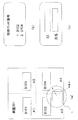
- Explanatory drawing which shows schematic structure of an imaging assistance system Functional block diagram showing functions of medical imaging apparatus and imaging support server It is explanatory drawing which shows the example of a search range and a screen display, (a) shows a search range, (b) shows a screen display example of a candidate bed number, (c) is a subject information input screen An example is shown.
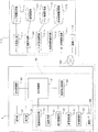
- the flowchart which shows the flow of a process of the imaging assistance system which concerns on 1st embodiment.
- Explanatory drawing showing an example of in-hospital map
- Explanatory drawing showing an example of the position and search range of a mobile X-ray device
- Explanatory drawing showing a screen display example of the mobile X-ray device 1 Functional block diagram showing functions of medical imaging apparatus and imaging support server The flowchart which shows the flow of a process of the imaging assistance system which concerns on 2nd embodiment.
- Functional block diagram showing functions of the mobile X-ray apparatus according to the third embodiment Explanatory drawing which shows schematic structure of the X-ray-image diagnostic apparatus used for 4th embodiment.
- Functional block diagram showing the configuration of the console 210 The flowchart which shows the flow of a process of the X-ray image diagnostic apparatus which concerns on 4th embodiment.
- An imaging support system is an examination target based on a medical image imaging device that generates a medical image of a subject, a position detection unit that detects a current position of the medical image imaging device, and the current position.
- a subject candidate search unit that searches for a subject candidate, a first operation unit that accepts a selection operation of the subject to be examined among the subject candidates, and an imaging condition of the subject to be examined are set
- An imaging condition setting unit .
- the imaging support system may further include a display unit that displays the set imaging condition and a second operation unit that receives an operation for changing the displayed imaging condition.
- the medical imaging device is a mobile device that moves in a facility
- the position detection unit calculates a current position of the mobile device in the facility
- the subject candidate search unit includes: The subject candidate may be searched based on the current position in the facility.
- the imaging support system may further include a map information storage unit that stores map information in which position information of each point in the facility is associated with the layout in the facility.
- the position calculation unit may calculate a current position in the facility with reference to the map information.
- the imaging support system includes a bed information storage unit that stores bed information in which position information of each point in the facility is associated with identification information of a bed arranged at each point, and the bed Each of the beds is used as a bed candidate search unit that searches for a bed within a predetermined range including the current position in the facility with reference to the information, and extracts the bed candidate as a bed candidate.
- a subject information storage unit that stores subject information associated with identification information of the subject that is being performed.
- the subject candidate search unit may extract the subject identification information associated with the bed candidate identification information extracted by the bed candidate search unit with reference to the subject information.
- the mobile device may further include a route storage unit that stores a route for performing inspection while moving in the facility.
- the bed candidate search unit may extract the bed on the route as the bed candidate.
- a route predicting unit that predicts a route to be inspected while the mobile device moves through the facility using the current position in the facility and the map information may be further provided.
- the bed candidate search unit may extract the bed on the predicted route as the bed candidate.
- the medical imaging apparatus may be connected to an imaging support server via a network.
- the medical imaging apparatus may include a position signal transmission unit that transmits a signal indicating the current position of the medical imaging apparatus to the imaging support server, the first operation unit, and the imaging condition setting unit.
- the imaging support server may include the position detection unit and the subject candidate search unit.
- the position detection unit may detect the current position of the medical imaging apparatus based on a signal indicating the current position transmitted from the position signal transmission unit.
- the imaging support system may further include a regional information storage unit that stores regional information indicating a standard body shape of a person living in the country or region where the medical imaging device is disposed.
- the position detection unit may include a region specifying unit that specifies a country or a region where the medical imaging device is disposed.
- the imaging condition setting unit refers to the region information about the country or region specified by the region specifying unit, and sets the imaging condition based on a standard figure of a person living in the country or region. Also good.
- the imaging support system further includes a display unit that displays the set imaging conditions, and a display control unit that selects a language used for the display screen of the display unit and displays the language on the display screen. May be.
- the regional information may further include language information used in the country or region.
- the display control unit refers to the geographical information about the country or region specified by the region specifying unit, and selects a language to be used on the display screen based on language information used in the country or region. , May be displayed.
- the first embodiment is an embodiment in which imaging conditions of a subject are automatically input based on a position in a facility during a round trip using a mobile device.
- a mobile X-ray apparatus 1 is used as an example of a medical imaging apparatus, and a hospital is taken as an example of a facility that uses the apparatus.
- the imaging support system according to the first embodiment will be described with reference to FIGS.
- FIG. 1 is an explanatory diagram showing a schematic configuration of the imaging support system.
- FIG. 2 is a functional block diagram illustrating functions of the medical image capturing apparatus and the imaging support server.
- FIG. 3 is an explanatory diagram showing an example of the search range and screen display, where (a) shows the search range, (b) shows a screen display example of candidate bed numbers, and (c) shows the subject range. The sample information input screen example is shown.
- FIG. 4 is a flowchart showing a process flow of the imaging support system according to the first embodiment.
- FIG. 5 is an explanatory diagram showing an example of an in-hospital map.
- FIG. 6 is an explanatory diagram showing an example of the position and search range of the mobile X-ray apparatus.
- FIG. 1 is an explanatory diagram showing a schematic configuration of the imaging support system.
- FIG. 2 is a functional block diagram illustrating functions of the medical image capturing apparatus and the imaging support server.
- FIG. 3 is an explanatory diagram showing an example of the search range
- FIG. 7 is an explanatory diagram showing an example of the bed information and subject information management table, where (a) shows the bed information and (b) shows the subject information management table.
- FIG. 8 is an explanatory diagram showing a screen display example of the mobile X-ray apparatus 1. As shown in FIG.
- An imaging support system 100 shown in FIG. 1 includes a mobile X-ray apparatus 1 and an imaging support server 110.
- the mobile X-ray apparatus 1 and the imaging support server 110 are connected via a network (for example, a hospital LAN) 120 by wired or wireless communication.
- a network for example, a hospital LAN
- an order information server 130 that stores order information including the imaging technique and imaging conditions of the subject.
- a RIS (Radiology Information System) server 130 will be described as an example of the order information server. Therefore, the order information server is hereinafter referred to as a RIS server.
- the medical image capturing apparatus is not limited to the mobile X-ray apparatus 1, and the present invention can also be applied to a mobile medical image capturing apparatus such as an ultrasonic diagnostic apparatus. Further, in the case of a non-radiation device such as an ultrasound diagnostic apparatus, the present invention can be applied by using a server that manages examination and treatment information based on these devices as the order information server 130.
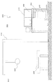
- the mobile X-ray apparatus 1 mainly includes a main body 2 and a moving carriage 3 that travels with the main body 2 mounted thereon.
- the movable carriage 3 includes a travel motor 62 and wheels 63, and travels by driving the wheels 63 with a motor.
- a prop 20 is erected in front of the movable carriage 3.
- On the upper part of the support column 20, an arm 21 constituted by a panta arm or a telescopic arm is provided.
- an X-ray generator 10 for generating X-rays and a diaphragm device 18 for limiting the X-ray irradiation range are provided.
- the positions of the X-ray generation unit 10 and the diaphragm device 18 can be moved so that the imaging region of the subject is irradiated with X-rays. Further, the arm 21 can be rotated in the circumferential direction with the longitudinal direction of the support column 20 as the rotation axis.
- the main body 2 further includes an operation unit 31 including a mouse, a keyboard, and a trackball, and a display unit 32 including a display panel configured using a liquid crystal monitor or the like.
- a control device 90 that controls the operation of the mobile X-ray device 1 is provided inside the main body 2.
- an X-ray detector 5 for detecting X-rays transmitted through the subject 4 is provided at a position facing the X-ray generation unit 10 with the subject 4 interposed therebetween.
- the X-ray detector 5 includes an FPD (Flat Panel Detector).
- the FPD is an example of an X-ray detector, and may be anything such as an imaging plate or an X-ray film as long as it can detect transmitted X-rays and generate an X-ray image or an X-ray image of a subject.
- the FPD may be wired or wirelessly connected to the main body 2 of the mobile X-ray apparatus 1 or may be a so-called portable FPD configured separately from the mobile X-ray apparatus 1.
- the FPD will be described as an example in which the FPD is wire-connected to the control device 90.
- an electric power unit 70 including a battery 71 for supplying power to each component of the mobile X-ray apparatus 1 is provided.
- a traveling handle 40 that is gripped when the operator travels the mobile X-ray apparatus 1 is provided on the opposite side of the main body 2 from the support column 20 (near the upper surface at the rear).
- an electromagnetic brake is provided, and when the operator grips the traveling handle 40, the electromagnetic brake is released to enable traveling, and when the operator releases the hand, the electromagnetic brake Is activated, and the mobile X-ray apparatus 1 is braked.
- the mobile X-ray apparatus 1 includes an operation unit 31, a display unit 32, a GPS receiver 33 that receives a GPS signal (Global Positioning System), and a control device 90.
- the control device 90 includes a central control unit 91 that performs various operation controls, a movement stop detection unit 92 that detects that the mobile X-ray device 1 has stopped, and imaging conditions (X-ray irradiation such as tube voltage and tube current).
- Detection condition setting unit 93 for setting the X-ray generator 10, an X-ray control unit 94 for controlling the operation of the X-ray generator 10, and a detection for performing a reading operation of the transmitted X-ray signal generated by the X-ray detector 5
- An instrument control unit 95 an image processing unit 96 for generating an X-ray image of the subject 4 based on the transmitted X-ray signal, an image storage unit 97 for storing the X-ray image, the mobile X-ray apparatus 1 and the external A communication interface (communication I / F) 98 for communicating with the apparatus.
- the mobile X-ray apparatus 1 is connected to the network 120 via the communication I / F 98.
- a GPS receiver is used as the position detection device, and the mobile X-ray device 1 includes the GPS receiver 33. It is desirable that the GPS receiver 33 can detect the position on the horizontal plane and the position on the vertical plane in the hospital by receiving three or more GPS signals and calculating the longitude, latitude, and altitude.
- the imaging support server 110 stores position information 111 that calculates the current position of the mobile X-ray apparatus 1 in the hospital, and map information that stores map information in which the position information of each point in the hospital is associated with the layout in the hospital
- the bed information storage unit 113 for storing bed information in which the storage unit 112, the position information of each point in the hospital, and the identification information of the bed arranged at each point are associated, the bed information, and the current position
- the bed candidate search unit 114 that searches for a bed within a predetermined range including and extracts the bed candidate, the identification information of each bed, and the identification information of the subject using each bed are associated with each other
- Object information storage unit 115 that stores object information, an object candidate search unit 116 that searches for an object candidate to be examined based on the current position, and information related to an examination scheduled to be performed on each object ,
- imaging site, imaging technique, X-ray It includes an order information acquisition unit 117 that acquires the order information including matters such as a communication interface (communication I / F)
- bed identification information does not uniquely identify each bed, but identifies where the bed is located in the hospital. Therefore, for example, if the bed before cleaning is removed as a result of cleaning and a new bed is placed at that position, the same bed number as that attached to the bed placed at that position before cleaning will be Attached.
- the room 501 is divided into four areas A1 to A4, the bed number located at A1 is B101, the bed number located at A2 is the bed located at B102, A3 The bed number located at B103 and the bed number located at A4 is designated in advance as B104.
- the bed of the bed number B101 arranged in A1 is moved to A2.
- the bed number of this bed is changed to B102.
- the bed number is associated with the position in the hospital on a 1: 1 basis.
- the position detection device that detects the position of the mobile X-ray device 1 is configured using the GPS reception device 33 and the position detection unit 111, but the position detection device is not limited to this.
- the mobile X-ray apparatus 1 includes a wireless transmitter (or a wireless receiver) and wireless receivers (or wireless transmitters) provided at various locations in the hospital, and these wireless transmitters and wireless receivers May be configured to detect the position of the mobile X-ray apparatus 1 depending on where a wireless receiver (or a wireless transmitter) is used.
- RFID Radio Frequency Identity
- an RF reader is installed in the mobile X-ray apparatus 1
- RFID tags are installed at various locations in the hospital.
- the mobile X-ray apparatus 1 may be configured to read the RFID tag while moving and calculate the current position of the mobile X-ray apparatus 1 based on the information of the RFID tag.
- an RFID tag may be installed in the mobile X-ray device 1 and an RF reader may be installed in each part of the hospital.
- an RFID tag is cheaper than an RF reader. It is preferable from the viewpoint of cost to install at each location.
- you may provide the apparatus which an operator inputs a bed number and a hospital room number as a position detection apparatus.
- Steps S101 to S103 In starting the round, the main power is turned on to the mobile X-ray apparatus 1 X-ray apparatus (S101). When the operator holds the traveling handle 40 and pushes it while releasing an electromagnetic brake (not shown), the mobile X-ray apparatus 1 starts moving (S102). The movement stop detection unit 92 determines whether or not the movement of the mobile X-ray apparatus 1 has stopped (S103). If the determination is affirmative, the process proceeds to step S104. If the determination is negative, the process returns to step S103.
- Step S104 When the movement stop is detected, the GPS receiver 33 receives the GPS signal, and the central control unit 91 transmits the signal to the server 110 via the communication I / F 98 (S104). That is, the central control unit 91 performs transmission control of GPS signals.
- Step S105 The position detection unit 111 receives a GPS signal via the communication I / F 118. Then, with reference to the map information stored in the map information storage unit 112, the current position of the mobile X-ray apparatus 1 and the search range centered on this current position are calculated (S105).
- the position detection unit 111 calculates the coordinates (X, Y, Z) of the current position of the mobile X-ray apparatus 1 based on the received GPS signal.
- the coordinates of the search range including the range of the radius R around the current position are obtained.
- the value of the radius R may be changed as appropriate. For example, when the bed interval or the width of each divided region is relatively small, the radius R is relatively small, and when the bed interval or the width of each divided region is relatively wide, the radius The value of R may be relatively large.
- the search range is depicted in a circle, but the search range may have a fan shape centered on the mobile X-ray apparatus 1, and the shape is not limited to a circle.
- the candidate area included in the radius R search range is calculated.
- the map information in FIG. 5 associates the layout in the hospital with the coordinates (X, Y) of each point in the hospital.
- the Z coordinate indicating the height direction (floor) in the hospital is also included, for convenience of explanation, FIG. 5 shows an in-hospital map on the same floor, and the Z coordinate is omitted.
- the bed candidate search unit 114 refers to the bed information stored in the bed information storage unit 113 and searches for a bed in the candidate area calculated in step S105 (S106).
- the bed searched as a result of this step is the bed candidate used by the subject to be examined.
- the bed information in (a) of FIG. 7 defines a hospital room number, an area number, and a bed number in association with each other.
- the data structure of the bed information is merely an example. For example, the coordinates of the position of each point in the hospital may be directly associated with the bed number.
- the bed candidate searching unit 114 obtains a bed number corresponding to each divided area. When a room number is obtained as a candidate area, all bed numbers in the room are obtained. When a plurality of bed numbers are specified, priorities are assigned in order from the closest bed number.
- step S107 If the result of determination in this step is that there is a bed within the search range, the process proceeds to step S107, and if not, the process proceeds to step S113.
- the subject candidate search unit 116 extracts the subject name corresponding to the bed number obtained in step S106 from the subject information stored in the subject information storage unit 115 (S107), and the mobile X-ray The data is transmitted to the device 1 (S108).
- the subject name extracted in step S107 becomes a subject candidate.
- the bed number, ID information that can uniquely identify the subject, and the subject name are defined in association with each other.
- Step 109 The mobile X-ray apparatus 1 displays the received subject candidate name on the display unit 32 (S109). If there are a plurality of subject names, they are transmitted in the order of priority in the order of proximity to the mobile X-ray apparatus 1, and are arranged and displayed in that order as shown in FIG. 3 (b), for example.
- Steps S110 to S112 The operator confirms the displayed subject name (S110). If it is correct, a message to that effect is input from the operation unit 31 and transmitted to the imaging support server 110 (S111). If it is incorrect or a plurality of subject names are displayed, the subject name to be examined is input / selected and the subject name is transmitted to the server (S112). Thereafter, the process proceeds to step S116.
- Steps S113-115) If it is determined in step S105 that there is no candidate bed, the bed candidate search unit 114 notifies the mobile X-ray apparatus 1 that there is no candidate bed (S113).
- the central control unit 91 receives a notification that there is no candidate, the central control unit 91 can uniquely identify the subject name or the subject, for example, as shown in FIG. A screen capable of inputting at least one of the subject IDs is displayed on the display unit 32 (S114). The operator inputs the subject name from the operation unit 31. The central control unit 91 transmits the input subject name to the imaging support server 110 (S115). Thereafter, the process proceeds to step S116.
- the order information acquisition unit 117 acquires order information corresponding to the subject name specified in S111, S112, or S113 from the RIS server 130 (S116), and transmits it to the mobile X-ray apparatus 1 (S117).
- the order information here includes X-ray conditions (for example, mA, kV, mAs, etc.) corresponding to the examination procedure received by the subject.
- Step S118 The imaging condition setting unit 93 sets the X-ray condition included in the order information included in the received order information, and the display unit 32 displays the set value (S118).
- the order information acquisition unit 117 acquires and displays the order information of “Hitachi B male”.
- FIG. 8 shows a display example of the display unit 32 at the end of this step.
- the screen of FIG. 8 includes an “ID” field 81, a “date” field 82, a “name” field 83, a “Protocol” field 84, an “X-ray condition display” field 85, and an adjustment button 86.
- “Protocol” examination technique
- the X-ray conditions are tube voltage V1 and tube current M1.
- the operation button 86 By operating the operation button 86, the set values of the automatically input tube voltage and tube current can be increased or decreased, and the X-ray condition can be finely adjusted.
- Steps S119 to S121 The operator visually recognizes the displayed X-ray information (S119), and if it is correct, presses the X-ray exposure button and executes an inspection (S120).
- the X-ray control unit 94 emits X-rays
- the detector control unit 95 reads a transmitted X-ray signal from the FPD.
- the image processing unit 96 generates an X-ray image of the subject based on the transmitted X-ray signal, and the image storage unit 97 stores it.
- the X-ray image may be displayed on the display unit 32. If the displayed X-ray condition is wrong, the correction process is performed (S121), and then the inspection is started (S120). In this correction process, in addition to fine adjustment of the X-ray conditions, the subject information input screen shown in (c) of FIG. 3 is displayed again, and the correct subject name is entered to obtain the order information. , Including setting and display.
- the movement of the mobile X-ray device 1 is resumed (S122). If there is no next inspection, it is returned to the storage location and the main power supply is turned off to end the series of processes. If there is a next inspection, the process returns to step S103, and the processes after S103 are executed again (S123).
- the order information of the subject to be examined can be automatically input based on the position of the mobile X-ray apparatus 1 in the hospital, the labor of inputting the order information by the operator can be reduced. Can do. As a result, the load on the operator is reduced, and erroneous input of order information can be suppressed.
- the process of calculating the current position is started with the movement stop detection unit 92 detecting the movement stop of the mobile X-ray device 1, but the movement stop is detected (the electromagnetic brake is ON). It is also possible to measure the elapsed time since then and trigger the passage of a predetermined time.
- the mobile X-ray apparatus 1 may be provided with a subject information acquisition button so that the operator can start the processing from step S104 in FIG.
- the processing start area is described in advance in the map information in the hospital, and when the position detection unit 111 calculates that the processing start area is entered, the subject candidate is displayed on the display unit 32 using this as a trigger. It may be configured.
- the second embodiment is an embodiment in which a route at a round visit is stored and a subject candidate is searched along the round trip route.
- the second embodiment will be described with reference to FIGS.
- FIG. 9 is a functional block diagram illustrating functions of the medical image capturing apparatus and the imaging support server.
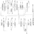
- FIG. 10 is a flowchart illustrating a processing flow of the imaging support system according to the second embodiment.
- the imaging support server 110a illustrated in FIG. 9 includes a path prediction unit 140 that predicts a roundabout path and a path storage unit 141 that stores the roundabout path in addition to the configuration of the imaging support server 110 of the first embodiment. Since other configurations are the same as those of the imaging server 110, description thereof is omitted. Further, since the medical imaging apparatus is the same as the mobile X-ray apparatus 1 used in the first embodiment, the description thereof is omitted. Hereinafter, the flow of the present embodiment will be described in the order of steps in FIG.
- Steps S201, S202 The main power supply of the mobile X-ray apparatus 1 is turned on (S201). After the main power is turned on, the GPS receiver 33 starts receiving the GPS signal and transmits it to the server 110a (S202). Further, after the main power is turned on, the operator moves the mobile X-ray apparatus 1.
- Step S203 The position detection unit 111 calculates the current position of the mobile X-ray device 1 (S203).
- Step S204 The route storage unit 141 stores the current position calculated in step S203 in time series (S204). A trajectory of the current position along the time series is stored as route information. In the route information, if the position where the inspection is performed is also stored, the execution order of the inspection along the route can be managed.
- the route prediction unit 140 refers to the route information in the route storage unit 141 and determines whether there is a roundabout route whose current position is on the route (S205). If there is, the roundabout route is determined as the predicted route (S206), and the process proceeds to step S208. If not, the process proceeds to step S207.
- the route prediction unit 140 refers to the map information stored in the map information storage unit 112 and predicts the route of the round visit (S207).
- the roundabout route is predicted by comparing the trajectory after the main power supply of S201 with a map in the hospital on the same floor, calculating a vector indicating the traveling direction of the mobile X-ray apparatus 1, and being positioned ahead of the traveling direction.
- the treatment may be performed by arranging hospital rooms or divided areas in order from a position relatively close to the mobile X-ray apparatus 1.
- the bed candidate search unit 114 searches for bed candidates on the roundabout route, and refers to the bed information stored in the bed information storage unit 113. Then, the bed number of each bed candidate is extracted, and a bed number list arranged in order along the roundabout path is created (S208).
- the “order along the roundabout route” is not necessarily the order close to the mobile X-ray apparatus 1. For example, in the roundabout path determined in step S206, if the round trip was made in the past from the current position of the mobile X-ray device 1, the bed number on the roundabout path is relatively Create a bed number list written in order from the farthest.
- the relative position from the current position of the mobile X-ray apparatus 1 out of the hospital room and the divided areas ahead of the traveling direction A bed number list arranged in order from the closest may be created.
- the bed number list creation algorithm may be configured so that it can be set as appropriate using a setting screen (not shown) provided separately.
- the subject candidate search unit 116 refers to the subject information stored in the subject information storage unit 115, extracts a subject candidate name corresponding to the bed number described in the bed number list, and moves the mobile X-ray apparatus It is transmitted to 1 (S209).
- Steps S210 and S211 Subject candidate names are displayed on the display unit 32 of the mobile X-ray apparatus 1 in the order described in the bed number list (S210). If the operator selects the name of the subject to be examined, the process proceeds to step S212. If not selected, the process returns to step S202, and the processes of steps S202 to S211 are repeatedly executed, that is, a loop process is performed. In step S205 in the second and subsequent loop processes, it is determined whether the robot moves along the roundabout path determined or predicted in the previous loop process. If the result of determination is that the patient is following the roundabout route, the process proceeds to step S206.
- step S207 the route prediction unit 140 predicts a new roundabout route based on the current position information. Thereby, the calculation of the current position and the prediction / determination of the roundabout route are performed again, and the subject candidate name is updated and displayed as the current position changes.
- Step S212 The central control unit 91 transmits the selected subject name to the imaging support server 110a (S212).
- Steps S213, S214 The order information acquisition unit 117 acquires the received order information of the subject name from the RIS server 130 (S213) and transmits it to the mobile X-ray apparatus 1 (S214).
- Steps S215 to S217) The imaging condition setting unit 93 sets the X-ray condition according to the received order information, and displays the set value on the display unit 32 (S215). The operator confirms whether the displayed content is correct (S216). If the display content is correct, the process proceeds to step S218. If there is an error in the display content, X-ray information correction processing is performed (S217).
- the correction processing here includes manually re-inputting the subject name and transmitting it to the imaging support server 110a to reacquire the order information and finely adjust the X-ray conditions. Thereafter, the process proceeds to step S218.
- Steps S218 to S219) The operator performs an inspection (S218).
- the central control unit 91 notifies the imaging support server 110a of the completion of the inspection (S219).
- the bed candidate search unit 114 creates a new bed number list in which the bed number of the subject whose examination has been completed is deleted from the bed number list created in S208 (S220).
- the processing from step S201 to step S220 is repeatedly executed until the main power source is turned off.
- the round trip path is predicted, and the subject that can be the examination target is searched and displayed at any time, so when the subject actually moves to the vicinity of the subject to be examined, It is possible to display the subject with higher priority. Since the order information can be automatically input by selecting the subject, the preparation time required to start the examination after being positioned in the vicinity of the subject is further shortened.
- the third embodiment is an embodiment in which the mobile X-ray apparatus 1 alone performs calculation of the current position, calculation of area information, identification of the bed number and subject name.
- the third embodiment will be described with reference to FIG.
- FIG. 11 is a functional block diagram showing functions of the mobile X-ray apparatus according to the third embodiment.
- the mobile X-ray device 1a in addition to the configuration of the control device 90 of the first embodiment, further includes a position detection unit 111, a map information storage unit 112, a bed information storage A unit 113, a bed candidate search unit 114, a subject information storage unit 115, a subject candidate search unit 116, and an order information acquisition unit 117 are mounted. Since the mobile X-ray apparatus 1 is desirably small and lightweight, the hardware that can be mounted can be limited. In that case, only the in-hospital map of the floor where the mobile X-ray device 1 is used and the information on the subject who is admitted to that floor are stored in each storage unit of the mobile X-ray device 1 to reduce the size of the hardware. -You may comprise so that the request
- the GPS receiver 33 receives a GPS signal.
- the position detection unit 111 calculates the current position and search range based on the GPS signal.
- map information stored in the map information storage unit 112 is calculated, and a candidate area is calculated.
- the bed candidate search unit 114 refers to the bed information stored in the bed information storage unit 113 and identifies the bed number in the candidate area.
- the subject candidate search unit 116 refers to the subject information storage unit 115, extracts subject candidate names corresponding to the bed numbers in the candidate area, and displays them on the display unit 32.
- the order information acquisition unit 117 acquires the order information from the RIS server 130 via the network 120.
- the imaging condition setting unit 93 sets the X-ray condition based on the acquired order information, and the set value is displayed on the display unit 32.
- connection to the network is unnecessary, contributing to the reduction of network congestion, and faster processing up to the automatic input of order information. Can be expected to do.
- the path calculation unit 140 and the path storage unit 141 May be configured so that the round trip route search can be executed by the mobile X-ray apparatus 1 alone without connecting to the network.
- FIG. 12 is an explanatory diagram showing a schematic configuration of the X-ray image diagnostic apparatus used in the fourth embodiment.
- FIG. 13 is a functional block diagram showing the configuration of the console 210.
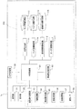
- FIG. 14 is a flowchart showing a flow of processing of the X-ray image diagnostic apparatus according to the fourth embodiment.
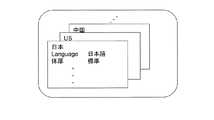
- FIG. 15 is an explanatory diagram illustrating an example of the area information stored in the area information storage unit.
- FIG. 12 shows a stationary X-ray diagnostic imaging apparatus 200.
- the X-ray diagnostic imaging apparatus 200 includes an X-ray generator 220 and an X-ray detector 230 installed in the imaging room 300, and a console installed in the operation room 320 adjacent to the imaging room 300 with the partition wall 310 interposed therebetween. 210.
- the X-ray generator 220 may be an overhead traveling X-ray generator that navigates along a ceiling rail disposed on the ceiling of the imaging room 300, for example. Opposite to the X-ray generator 220, an X-ray detector 230 for detecting transmitted X-rays of the subject is provided.
- the console 210 includes a control device 240 that controls various operations of the X-ray image diagnostic apparatus 200, an operation unit 250, a display unit 260, and a GPS receiver 270.
- the control device 240 includes a central control unit 241 that performs various operation controls, and a region specifying unit 242 that specifies the country or region in which the X-ray diagnostic imaging apparatus 200 is installed based on the GPS signal. Select the language used for the GUI, display text information on the GUI using that language, and the region that shows the language used in each country or region and the standard figure of people living in that region X-ray control for controlling the X-ray generator 220 and the imaging condition setting unit 245 for calculating and setting the X-ray conditions based on the system information included in the area information, the regional information storage unit 244 storing the information Unit 246, a detector control unit 247 that performs a reading operation of the transmitted X-ray signal generated by the X-ray detector 230, an image processing unit 248 that generates an X-ray image of the subject based on the transmitted X-ray signal, An image storage unit 249 for storing X-ray images.
- Step S301 The main power supply of the X-ray diagnostic imaging apparatus 200 is turned on (S301).
- Step S302 The GPS receiver 270 receives a GPS signal (S302).
- Step S303 The region specifying unit 242 calculates the latitude and longitude based on the GPS signal, and specifies the country or region where the current position of the mobile X-ray apparatus 1 is included (S303).
- the area specifying unit 242 refers to the area data in the area information storage unit 243, reads out the area information of the country or area specified in step S303, and passes the area information to the display control unit 243 and the imaging condition setting unit 245 (S304). ).
- the regional information includes language (not limited to official languages) information for each country / region, standard body type information such as body thickness, and initial values of imaging conditions according to the body type information. Configured as a table containing.
- the display control unit 243 refers to the regional information and displays the GUI using the language of the country / region. Further, the imaging condition setting unit 245 refers to the area information, calculates a value such as an X-ray condition (for example, kV, mA), and sets the value as an X-ray condition (S305).
- a value such as an X-ray condition (for example, kV, mA)
- the region data related to Japan is read from the region information in FIG. 15 and the language used in the GUI is determined to be Japanese.
- the imaging condition setting unit 245 refers to the regional information on Japan in the regional information of FIG. 15, imaging conditions when the “body thickness” is “standard”, for example, X-ray conditions (kV, mA And the like are set as initial values.
- the standard (average) figure of people in countries and regions different from Japan is better than the standard (average) figure of Japanese people, for example, if the body thickness is thick
- the table that constitutes the regional information of the country or the region includes information indicating that the “body thickness” is “thick” and the X-ray conditions that match the standard (average) body thickness of the country or region. Is stipulated. Therefore, the country or region table is read, and the X-ray conditions defined in the table are set.
- the set X-ray conditions are displayed on the GUI shown in FIG. 8, for example. Then, by operating the adjustment button 86 in FIG. 8 to increase or decrease the set value, fine adjustment can be performed on the automatically input X-ray condition.
- information indicating the body type and imaging conditions are defined in the area information.
- the area information may include information indicating the body type and a separate table including a conversion table of imaging conditions suitable for the body type. good.
- the imaging condition setting unit 245 may read information indicating the body shape from the area information and determine the imaging condition with reference to the conversion table.
- the conversion table constitutes part of the regional information as information accompanying the regional information.
- the regional information may include an imaging condition that matches the standard body type of the country or region and does not include information indicating the standard body type.
- the imaging conditions may be determined in a subdivided manner according to the imaging technique and the imaging region, as well as the body shape.
- imaging conditions X-ray conditions
- X-ray conditions imaging conditions
- the number of work steps has increased, the number of work steps can be reduced.
- acquisition of subject information and setting of X-ray conditions according to the subject are manually input by a user such as a doctor or a nurse at a medical site, which puts a burden on the user. Automatic setting of X-ray conditions suitable for the country is possible, and the burden on the user can be reduced.
Landscapes
- Health & Medical Sciences (AREA)
- Life Sciences & Earth Sciences (AREA)
- Engineering & Computer Science (AREA)
- Medical Informatics (AREA)
- Radiology & Medical Imaging (AREA)
- Public Health (AREA)
- General Health & Medical Sciences (AREA)
- Nuclear Medicine, Radiotherapy & Molecular Imaging (AREA)
- High Energy & Nuclear Physics (AREA)
- Animal Behavior & Ethology (AREA)
- Optics & Photonics (AREA)
- Biomedical Technology (AREA)
- Heart & Thoracic Surgery (AREA)
- Molecular Biology (AREA)
- Surgery (AREA)
- Pathology (AREA)
- Physics & Mathematics (AREA)
- Biophysics (AREA)
- Veterinary Medicine (AREA)
- Epidemiology (AREA)
- Primary Health Care (AREA)
- Computer Networks & Wireless Communication (AREA)
- Apparatus For Radiation Diagnosis (AREA)
Description
第一実施形態は、移動型装置を用いた回診中に、施設内の位置を基に被検体の撮像条件を自動入力する実施形態である。第一実施形態では、医用画像撮像装置の例として移動型X線装置1を用い、これを使用する施設として病院を例に挙げて説明する。以下、図1乃至図8に基づいて、第一実施形態に係る撮像支援システムについて説明する。
回診を始めるにあたり、移動型X線装置1X線装置に主電源を投入する(S101)。
操作者が、走行ハンドル40を把持して図示しない電磁ブレーキを解除しながら押し進めることで、移動型X線装置1が移動を開始する(S102)。移動停止検知部92は、移動型X線装置1の移動が停止したか否かを判断する(S103)。肯定であればステップS104へ進み、否定であれば、ステップS103に戻る。
移動停止を検知すると、GPS受信器33がGPS信号を受信し、中央制御部91が通信I/F98を介してサーバ110に送信する(S104)。すなわち、中央制御部91は、GPS信号の送信制御を行う。
位置検出部111は、通信I/F118を介してGPS信号を受信する。そしてマップ情報記憶部112に記憶されたマップ情報を参照し、移動型X線装置1の現在位置及びこの現在位置を中心とする検索範囲を算出する(S105)。
ベッド候補検索部114は、ベッド情報記憶部113に記憶されたベッド情報を参照し、ステップS105で算出された候補エリア内にベッドがあるか検索する(S106)。
被検体候補検索部116は、被検体情報記憶部115に記憶された被検体情報の中から、ステップS106で求められたベッド番号に対応する被検体名を抽出し(S107)、移動型X線装置1に送信する(S108)。ステップS107で抽出された被検体名が、被検体候補となる。図7の(b)の被検体情報では、ベッド番号と、被検体を固有に識別可能なID情報と、被検体名と、を対応付けて規定している。ステップS106で複数のベッド番号が求められた場合には、各ベッドに対応する被検体名を特定する。
移動型X線装置1は、受信した被検体候補名を表示部32に表示する(S109)。複数の被検体名がある場合は、移動型X線装置1に近い順に優先順位を付けて送信し、例えば図3の(b)に示すように、その順に沿って整列して表示する。
操作者は、表示された被検体名の確認を行う(S110)。正しければ、その旨を操作部31から入力し、撮像支援サーバ110に対して送信する(S111)。誤っているとき及び複数の被検体名が表示された場合には、検査対象となる被検体名を入力・選択し、その被検体名をサーバに送信する(S112)。その後、ステップS116へ進む。
ステップS105で候補ベッドが無いと判断されると、ベッド候補検索部114は、移動型X線装置1に候補ベッドがないことを通知する(S113)。中央制御部91は、候補がない通知を受け取ると、操作者に被検体名を入力させるための画面、例えば図3の(c)に示すように被検体名または被検体を固有に識別可能な被検体IDの少なくとも一方を入力可能な画面を表示部32に表示する(S114)。操作者は、操作部31から被検体名を入力する。中央制御部91は、入力された被検体名を撮像支援サーバ110に送信する(S115)。その後、ステップS116へ進む。
オーダ情報取得部117は、RISサーバ130からS111、S112、又はS113で特定された被検体名に対応するオーダ情報を取得(S116)し、移動型X線装置1へ送信する(S117)。ここでいうオーダ情報には、当該被検体が受ける検査手技に対応したX線条件(例えばmA、kV、mAsなど)が含まれる。
撮像条件設定部93は、受信したオーダ情報に含まれるオーダ情報に含まれるX線条件を設定し、表示部32は、その設定値を表示する(S118)。ステップS111、S112、又はS113で特定された被検体名が「日立B男」の場合、オーダ情報取得部117は、「日立B男」のオーダ情報を取得し、表示する。
操作者は、表示されたX線情報を視認し(S119)、正しければX線曝射ボタンを押し下げ、検査を実行する(S120)。設定されたX線条件にしたがってX線制御部94がX線を照射し、検出器制御部95がFPDから透過X線信号を読み出す。画像処理部96は、透過X線信号を基に被検体のX線画像を生成し、画像記憶部97が記憶する。X線画像は、表示部32に表示してもよい。表示されたX線条件が間違っていれば修正処理を行った後(S121)、検査を開始する(S120)。ここでいう修正処理には、X線条件の微調整の他、再度、図3の(c)に示す被検体情報の入力画面の表示を行い、正しい被検体名を入力してオーダ情報の取得、設定、表示を行う場合を含む。
第二実施形態は、回診時の経路を記憶しておき、回診の経路に沿って被検体候補を検索する実施形態である。以下、図9及び図10を用いて第二実施形態について説明する。図9は、医用画像撮像装置及び撮像支援サーバの機能を示す機能ブロック図である。図10は、第二実施形態に係る撮像支援システムの処理の流れを示すフローチャートである。
移動型X線装置1の主電源を投入する(S201)。主電源投入後、GPS受信器33はGPS信号の受信を開始し、サーバ110aに送信する(S202)。また、主電源投入後、操作者が移動型X線装置1を移動させる。
位置検出部111は、移動型X線装置1の現在位置を算出する(S203)。
経路記憶部141は、ステップS203で算出された現在位置を、時系列に沿って記憶する(S204)。時系列に沿った現在位置の軌跡が、経路情報として記憶される。経路情報には、検査を実行した位置も合わせて記憶しておくと、その経路に沿った検査の実行順も管理できる。
経路予測部140は、経路記憶部141の経路情報を参照し、現在位置が経路上にある回診経路があるか否かの判定を行う(S205)。あれば、この回診経路を予測経路と決定して(S206)、ステップS208へ進む。なければステップS207へ進む。
経路がない場合は、経路予測部140はマップ情報記憶部112に記憶されたマップ情報を参照し、回診の経路を予測する(S207)。回診経路の予測は、例えば、同一階の病院内のマップにS201の主電源投入後の軌跡を照らし合わせ、移動型X線装置1の進行方向を示すベクトルを演算し、進行方向先に位置する病室や分割領域を、移動型X線装置1に相対的に近い位置から順に沿って並べることで行ってもよい。
ベッド候補検索部114は、回診経路上にあるベッド候補を検索し、ベッド情報記憶部113に記憶されたベッド情報を参照する。そして、各ベッド候補のベッド番号を抽出し、回診経路に沿った順に整列したベッドナンバーリストを作成する(S208)。「回診経路に沿った順」とは、必ずしも移動型X線装置1に近い順とは限らない。例えば、ステップS206で決定された回診経路では、過去に移動型X線装置1の現在位置よりも遠いところから順に回診していた場合には、回診経路上にあるベッド番号の内、相対的に遠いものから順に記載されたベッドナンバーリストを作成する。一方、ステップS207で予測した回診経路の場合、今回新しく予測している回診経路であるので、進行方向先に位置する病室や分割領域のうち、移動型X線装置1の現在位置から相対的に近いものから順に整列したベッドナンバーリストを作成してもよい。ベッドナンバーリストの作成アルゴリズムは、別途設けられた設定画面(図示を省略)を用いて、遠い順または近い順等、適宜設定できるように構成してもよい。
被検体候補検索部116は、被検体情報記憶部115に記憶された被検体情報を参照し、ベッドナンバーリストに記載されたベッド番号に対応する被検体候補名を抽出し、移動型X線装置1に送信する(S209)。
移動型X線装置1の表示部32にベッドナンバーリストに記載された順に沿って、被検体候補名が表示される(S210)。操作者が検査対象の被検体名を選択するとステップS212へ進み、選択をしない場合にはステップS202へ戻り、ステップS202~S211の処理を繰り返し実行する、すなわちループ処理を行う。2回目以降のループ処理におけるステップS205では、その前のループ処理で決定又は予測された回診経路上に沿って移動しているか判定する。判定した結果、回診経路に沿っている場合は、ステップS206へ進む。一方、回診経路に沿っていない場合は、ステップS207へ進み、経路予測部140が、現在の位置情報を基に新たな回診経路を予測する。これにより、現在位置の算出、回診経路の予測・決定が再度行われ、現在位置の変化に伴って被検体候補名の更新表示が行われる。
中央制御部91は、撮像支援サーバ110aに選択された被検体名を送信する(S212)。
オーダ情報取得部117は、受信した被検体名のオーダ情報をRISサーバ130から取得し(S213)、移動型X線装置1へ送信する(S214)。
撮像条件設定部93は、受信したオーダ情報に従ってX線条件を設定し、その設定値を表示部32に表示する(S215)。操作者は、表示内容が正しいか確認する(S216)。表示内容が正しければステップS218へ進む。表示内容に誤りがあれば、X線情報の修正処理を行う(S217)。ここでいう修正処理とは、被検体名を手入力し直し、撮像支援サーバ110aに送信し、オーダ情報の再取得や、X線条件を増減して微調整をすることを含む。その後、ステップS218へ進む。
操作者が検査を実行する(S218)。検査が終了すると、中央制御部91は撮像支援サーバ110aに検査終了通知を行う(S219)。
第三実施形態は、移動型X線装置1単独で、現在位置の算出、エリア情報の算出、ベッド番号及び被検体名の特定を行う実施形態である。以下、図11を用いて第三実施形態について説明する。図11は、第三実施形態に係る移動型X線装置の機能を示す機能ブロック図である。
位置検出部111は、GPS信号を基に現在位置及び検索範囲を算出する。そして、マップ情報記憶部112に記憶されたマップ情報を算出し、候補エリアを算出する。ベッド候補検索部114が、ベッド情報記憶部113に記憶されたベッド情報を参照し、候補エリア内のベッド番号を特定する。被検体候補検索部116は、被検体情報記憶部115を参照し、候補エリア内のベッド番号に対応した被検体候補名を抽出し、表示部32に表示する。
第四実施形態は、GPS信号を基に、GUI(Graphical User Interface)に使用する言語や、移動型X線装置1が使用される地域に居住する人々の体格にあったX線条件を自動入力する実施形態である。なお、本実施形態は、第一実施形態から第三実施形態のいずれとも組み合わせることができる。以下、図12乃至図15を用いて説明する。図12は、第四実施形態に用いるX線画像診断装置の概略構成を示す説明図である。図13は、操作卓210の構成を示す機能ブロック図である。図14は、第四実施形態に係るX線画像診断装置の処理の流れを示すフローチャートである。図15は、地域情報記憶部に記憶された地域情報の一例を示す説明図である。
X線画像診断装置200の主電源を投入する(S301)。
GPS受信器270は、GPS信号を受信する(S302)。
地域特定部242は、GPS信号を基に緯度・経度を算出し、移動型X線装置1の現在位置が含まれる国又は地域を特定する(S303)。
地域特定部242は、地域情報記憶部243の地域データを参照し、ステップS303で特定した国又は地域の地域情報を読み出し、その地域情報を表示制御部243及び撮像条件設定部245に引き渡す(S304)。図15に示すように、地域情報は、国・地域別の言語(公用語に限らない)情報、及び体厚などの標準的な体型情報、およびその体型情報に応じた撮像条件の初期値を含むテーブルとして構成される。
表示制御部243は、地域情報を参照し、その国・地域の言語を用いてGUIの表示を行う。また、撮像条件設定部245は、地域情報を参照し、X線条件(例えばkV、mA)などの値を算出し、その値を、X線条件として設定する(S305)。
Claims (11)
- 被検体の医用画像を生成する医用画像撮像装置と、
前記医用画像撮像装置の現在位置を検出する位置検出部と、
前記現在位置を基に、検査対象となる被検体候補を検索する被検体候補検索部と、
前記被検体候補のうち、前記検査対象となる被検体の選択操作を受け付ける第一操作部と、
前記検査対象となる被検体の撮像条件を設定する撮像条件設定部と、
を備えることを特徴とする撮像支援システム。 - 前記設定された撮像条件を表示する表示部と、
前記表示された撮像条件の変更操作を受け付ける第二操作部と、
を備えることを特徴とする請求項1に記載の撮像支援システム。 - 前記医用画像撮像装置は、施設内を移動する移動型装置であり
前記位置検出部は、前記施設内における前記移動型装置の現在位置を算出し、
前記被検体候補検索部は、前記施設内の現在位置を基に、前記被検体候補を検索する、 ことを特徴とする請求項2に記載の撮像支援システム。 - 前記施設内のレイアウトに前記施設内の各点の位置情報を対応付けたマップ情報を記憶するマップ情報記憶部を更に備え、
前記位置検出部は、前記マップ情報を参照して、前記施設内の現在位置を算出する、
ことを特徴とする請求項3に記載の撮像支援システム。 - 前記施設内の各点の位置情報に、前記各点に配置されたベッドの識別情報を対応付けたベッド情報を記憶するベッド情報記憶部と、
前記ベッド情報を参照し、前記施設内の現在位置を含む所定の範囲内にあるベッドを検索し、ベッド候補として抽出するベッド候補検索部と、
前記ベッドの識別情報の各々に、前記ベッドの各々を使用している被検体の識別情報を対応付けた被検体情報を記憶する被検体情報記憶部と、を更に備え、
前記被検体候補検索部は、前記被検体情報を参照し、前記ベッド候補検索部が抽出した前記ベッド候補の識別情報に対応付けられた前記被検体の識別情報を抽出する、
ことを特徴とする請求項4に記載の撮像支援システム。 - 前記移動型装置が前記施設内を移動しながら検査を行う経路を記憶する経路記憶部を更に備え、
前記ベッド候補検索部は、前記経路上にある前記ベッドを、前記ベッド候補として抽出する、
ことを特徴とする請求項5の記載の撮像支援システム。 - 前記施設内の現在位置及び前記マップ情報を用いて、前記移動型装置が前記施設内を移動しながら検査を行う経路を予測する経路予測部を更に備え、
前記ベッド候補検索部は、前記予測された経路上にある前記ベッドを、前記ベッド候補として抽出する、
ことを特徴とする請求項5の記載の撮像支援システム。 - 前記医用画像撮像装置は、撮像支援サーバにネットワークを介して接続されるとともに、当該医用画像撮像装置の現在位置を示す信号を前記撮像支援サーバに送信する位置信号送信部、前記第一操作部、及び、前記撮像条件設定部を含み、
前記撮像支援サーバは、前記位置検出部及び前記被検体候補検索部を含み、
前記位置検出部は、前記位置信号送信部から送信された前記現在位置を示す信号を基に、前記医用画像撮像装置の現在位置を検出する、
ことを特徴とする請求項1に記載の撮像支援システム。 - 前記医用画像撮像装置が配置されている国又は地域に居住する人の、標準的な体型を示す地域情報を記憶する地域情報記憶部を更に備え、
前記位置検出部は、前記医用画像撮像装置が配置されている国又は地域を特定する地域特定部を含み、
前記撮像条件設定部は、前記地域特定部が特定した国又は地域についての前記地域情報を参照し、当該国又は地域に居住する人の標準的な体型を基に撮像条件を設定する、
ことを特徴とする請求項1に記載の撮像支援システム。 - 前記設定された撮像条件を表示する表示部と、
前記表示部の表示画面に使用する言語を選択し、前記表示画面に表示する表示制御部と、を更に備え、
前記地域情報は、前記国または地域で用いられる言語情報を更に含み、
前記表示制御部は、前記地域特定部が特定した国又は地域についての前記地域情報を参照し、当該国又は地域で用いられる言語情報を基に、前記表示画面で使用する言語を選択し、表示する、
ことを特徴とする請求項9に記載の撮像支援システム。 - 被検体を撮像する撮像部を備えた医用画像撮像装置であって、
前記医用画像撮像装置の現在位置を検出する位置検出部と、
前記現在位置を基に、検査対象となる被検体候補を検索する被検体候補検索部と、
前記被検体候補のうち、前記検査対象となる被検体の選択操作を受け付ける操作部と、 前記検査対象となる被検体の撮像条件を設定する撮像条件設定部と、
を備えることを特徴とする医用画像撮像装置。
Priority Applications (3)
| Application Number | Priority Date | Filing Date | Title |
|---|---|---|---|
| JP2014536776A JPWO2014045958A1 (ja) | 2012-09-19 | 2013-09-11 | 撮像支援システム及び医用画像撮像装置 |
| CN201380040511.XA CN104519797B (zh) | 2012-09-19 | 2013-09-11 | 摄像支持系统以及医用图像摄像装置 |
| US14/419,160 US20150201899A1 (en) | 2012-09-19 | 2013-09-11 | Imaging support system and medical image imaging apparatus |
Applications Claiming Priority (2)
| Application Number | Priority Date | Filing Date | Title |
|---|---|---|---|
| JP2012-205730 | 2012-09-19 | ||
| JP2012205730 | 2012-09-19 |
Publications (1)
| Publication Number | Publication Date |
|---|---|
| WO2014045958A1 true WO2014045958A1 (ja) | 2014-03-27 |
Family
ID=50341272
Family Applications (1)
| Application Number | Title | Priority Date | Filing Date |
|---|---|---|---|
| PCT/JP2013/074486 Ceased WO2014045958A1 (ja) | 2012-09-19 | 2013-09-11 | 撮像支援システム及び医用画像撮像装置 |
Country Status (4)
| Country | Link |
|---|---|
| US (1) | US20150201899A1 (ja) |
| JP (1) | JPWO2014045958A1 (ja) |
| CN (1) | CN104519797B (ja) |
| WO (1) | WO2014045958A1 (ja) |
Cited By (3)
| Publication number | Priority date | Publication date | Assignee | Title |
|---|---|---|---|---|
| JP2015188581A (ja) * | 2014-03-28 | 2015-11-02 | 株式会社日立メディコ | X線画像制御装置 |
| JP2016209076A (ja) * | 2015-04-30 | 2016-12-15 | 株式会社トプコン | 眼科装置およびその制御方法 |
| JP2022500111A (ja) * | 2018-09-07 | 2022-01-04 | エシコン エルエルシーEthicon LLC | モジュール式エネルギーシステムの構成要素の地域位置追跡 |
Families Citing this family (8)
| Publication number | Priority date | Publication date | Assignee | Title |
|---|---|---|---|---|
| US10271802B2 (en) * | 2014-08-12 | 2019-04-30 | Carestream Health, Inc. | Digital x-ray imaging apparatus and method |
| KR20160042572A (ko) * | 2014-10-10 | 2016-04-20 | 삼성전자주식회사 | 방사선 촬영 장치, 방사선 촬영 장치의 제어 방법 및 컴퓨터 단층 촬영 장치 |
| JP6525681B2 (ja) * | 2015-03-31 | 2019-06-05 | キヤノン株式会社 | 撮影システム、制御装置およびその制御方法 |
| JP6599913B2 (ja) * | 2017-02-28 | 2019-10-30 | 株式会社メディカロイド | ロボット手術台用操作装置 |
| JP6568884B2 (ja) * | 2017-02-28 | 2019-08-28 | 株式会社メディカロイド | ロボット手術台およびロボット手術台用操作装置 |
| US11166695B2 (en) * | 2018-04-09 | 2021-11-09 | Carestream Health, Inc. | Learning system and method for mobile radiography power management |
| CN111358487A (zh) * | 2018-12-25 | 2020-07-03 | 无锡祥生医疗科技股份有限公司 | 超声诊断设备自主导航方法、系统和超声设备 |
| JP2022182028A (ja) * | 2021-05-27 | 2022-12-08 | キヤノン株式会社 | 放射線撮影装置、放射線検出器、および放射線撮影装置の制御装置 |
Citations (6)
| Publication number | Priority date | Publication date | Assignee | Title |
|---|---|---|---|---|
| JP2004041698A (ja) * | 2002-05-21 | 2004-02-12 | Canon Inc | 移動型放射線撮影装置、放射線撮影システム、放射線撮影方法、プログラム、コンピュータ可読記憶媒体、及び情報システム |
| JP2005278727A (ja) * | 2004-03-29 | 2005-10-13 | Senoo:Kk | Pda等の携帯端末機器からの指令により動作する医療放射線ポータブル撮影装置制御システム |
| JP2006340788A (ja) * | 2005-06-07 | 2006-12-21 | Shimadzu Corp | 撮影情報管理システム及びこれに用いられる移動型x線撮影装置 |
| JP2007044136A (ja) * | 2005-08-08 | 2007-02-22 | Shimadzu Corp | 移動型x線撮影装置の撮影情報管理システム |
| JP2010284423A (ja) * | 2009-06-15 | 2010-12-24 | Toshiba Corp | 医用画像診断装置及び医用画像撮影方法 |
| WO2012033028A1 (ja) * | 2010-09-07 | 2012-03-15 | 株式会社 日立メディコ | X線ct装置および管電流決定方法 |
Family Cites Families (9)
| Publication number | Priority date | Publication date | Assignee | Title |
|---|---|---|---|---|
| CA2328545A1 (en) * | 2000-05-30 | 2001-11-30 | Visualmed Clinical Systems Corporation | Hospital informatics system |
| US7756723B2 (en) * | 2001-09-07 | 2010-07-13 | Eclipsys Corporation | System and method for managing patient bed assignments and bed occupancy in a health care facility |
| US7430608B2 (en) * | 2001-12-04 | 2008-09-30 | Siemens Medical Solutions Usa, Inc. | System for processing data acquired from multiple medical devices |
| US7016467B2 (en) * | 2004-08-13 | 2006-03-21 | Jack Jerome Brooks | Mobile digital radiography x-ray apparatus and system |
| US7593918B2 (en) * | 2004-11-24 | 2009-09-22 | General Electric Company | Enterprise medical imaging and information management system with enhanced communications capabilities |
| US7813941B2 (en) * | 2006-07-26 | 2010-10-12 | Siemens Medical Solutions Usa, Inc. | Patient bed search system |
| US8983663B2 (en) * | 2006-10-17 | 2015-03-17 | General Electric Company | Self-guided portable medical diagnostic system |
| US8280748B2 (en) * | 2006-10-20 | 2012-10-02 | Hill-Rom Services, Inc. | Bed management |
| FR2953119B1 (fr) * | 2009-12-01 | 2012-07-27 | Gen Electric | Base mobile et appareil a rayons x monte sur une telle base mobile |
-
2013
- 2013-09-11 WO PCT/JP2013/074486 patent/WO2014045958A1/ja not_active Ceased
- 2013-09-11 JP JP2014536776A patent/JPWO2014045958A1/ja not_active Ceased
- 2013-09-11 US US14/419,160 patent/US20150201899A1/en not_active Abandoned
- 2013-09-11 CN CN201380040511.XA patent/CN104519797B/zh not_active Expired - Fee Related
Patent Citations (6)
| Publication number | Priority date | Publication date | Assignee | Title |
|---|---|---|---|---|
| JP2004041698A (ja) * | 2002-05-21 | 2004-02-12 | Canon Inc | 移動型放射線撮影装置、放射線撮影システム、放射線撮影方法、プログラム、コンピュータ可読記憶媒体、及び情報システム |
| JP2005278727A (ja) * | 2004-03-29 | 2005-10-13 | Senoo:Kk | Pda等の携帯端末機器からの指令により動作する医療放射線ポータブル撮影装置制御システム |
| JP2006340788A (ja) * | 2005-06-07 | 2006-12-21 | Shimadzu Corp | 撮影情報管理システム及びこれに用いられる移動型x線撮影装置 |
| JP2007044136A (ja) * | 2005-08-08 | 2007-02-22 | Shimadzu Corp | 移動型x線撮影装置の撮影情報管理システム |
| JP2010284423A (ja) * | 2009-06-15 | 2010-12-24 | Toshiba Corp | 医用画像診断装置及び医用画像撮影方法 |
| WO2012033028A1 (ja) * | 2010-09-07 | 2012-03-15 | 株式会社 日立メディコ | X線ct装置および管電流決定方法 |
Cited By (3)
| Publication number | Priority date | Publication date | Assignee | Title |
|---|---|---|---|---|
| JP2015188581A (ja) * | 2014-03-28 | 2015-11-02 | 株式会社日立メディコ | X線画像制御装置 |
| JP2016209076A (ja) * | 2015-04-30 | 2016-12-15 | 株式会社トプコン | 眼科装置およびその制御方法 |
| JP2022500111A (ja) * | 2018-09-07 | 2022-01-04 | エシコン エルエルシーEthicon LLC | モジュール式エネルギーシステムの構成要素の地域位置追跡 |
Also Published As
| Publication number | Publication date |
|---|---|
| CN104519797B (zh) | 2017-04-26 |
| US20150201899A1 (en) | 2015-07-23 |
| JPWO2014045958A1 (ja) | 2016-08-18 |
| CN104519797A (zh) | 2015-04-15 |
Similar Documents
| Publication | Publication Date | Title |
|---|---|---|
| WO2014045958A1 (ja) | 撮像支援システム及び医用画像撮像装置 | |
| CN102258376B (zh) | 具有跟踪特征的手持x射线系统接口 | |
| CN103654809B (zh) | 用于自动定位x射线设备的拍摄系统的方法和x射线设备 | |
| CN102258373B (zh) | 手持x射线系统接口装置和方法 | |
| US8331530B2 (en) | Handheld X-ray image viewing system and method | |
| US20200085385A1 (en) | Virtual positioning image for use in imaging | |
| US20110288853A1 (en) | Handheld device control of an x-ray system | |
| US11076818B2 (en) | Method for operating an x-ray device with an articulated arm, and x-ray device with an articulated arm | |
| US10603000B2 (en) | Radiography system and method for operating radiography system | |
| US9757079B2 (en) | Method for controlling the spatial position of a direct digital X-ray detector | |
| US9196152B2 (en) | System, method, and software for location assisted mapping and patient monitoring | |
| KR102004642B1 (ko) | 방사선촬영 모의시스템에 의하여 수행되는 방사선 모의촬영 제어방법 | |
| JP2008220553A (ja) | 放射線治療システム | |
| EP4536085B1 (en) | Auto positioning of x-ray tube support with respect to detector | |
| CN119968185A (zh) | 一种移动式病床与医疗设备的对接控制方法和系统 | |
| JP2013255741A (ja) | X線装置及びx線撮像装置 | |
| JP2015191555A (ja) | 携帯型コンソール、携帯型コンソールの制御方法、携帯型コンソールの制御プログラム、及び撮影スキル分析システム | |
| CN111148472A (zh) | 用于定位移动医学成像系统的系统和方法 | |
| US20230360253A1 (en) | Medical information processing system and medical information processing apparatus | |
| JP2011072535A (ja) | 医用画像撮影システム | |
| US20200037980A1 (en) | Photographing sequence determination supporting method, photographing sequence determination supporting program, and x-ray radiographic apparatus equipped therewith | |
| JP2023026883A (ja) | 制御装置、制御方法、放射線撮像システム及びプログラム | |
| JP2011212031A (ja) | 放射線画像撮影システム | |
| JP2014033953A (ja) | X線診断装置 | |
| US11890126B2 (en) | Radiation imaging apparatus |
Legal Events
| Date | Code | Title | Description |
|---|---|---|---|
| 121 | Ep: the epo has been informed by wipo that ep was designated in this application |
Ref document number: 13838152 Country of ref document: EP Kind code of ref document: A1 |
|
| ENP | Entry into the national phase |
Ref document number: 2014536776 Country of ref document: JP Kind code of ref document: A |
|
| WWE | Wipo information: entry into national phase |
Ref document number: 14419160 Country of ref document: US |
|
| NENP | Non-entry into the national phase |
Ref country code: DE |
|
| 122 | Ep: pct application non-entry in european phase |
Ref document number: 13838152 Country of ref document: EP Kind code of ref document: A1 |