WO2014045936A1 - 磁気共鳴イメージング装置および磁気共鳴イメージング方法 - Google Patents
磁気共鳴イメージング装置および磁気共鳴イメージング方法 Download PDFInfo
- Publication number
- WO2014045936A1 WO2014045936A1 PCT/JP2013/074353 JP2013074353W WO2014045936A1 WO 2014045936 A1 WO2014045936 A1 WO 2014045936A1 JP 2013074353 W JP2013074353 W JP 2013074353W WO 2014045936 A1 WO2014045936 A1 WO 2014045936A1
- Authority
- WO
- WIPO (PCT)
- Prior art keywords
- pulse
- selective excitation
- excitation
- dimensional
- sequence
- Prior art date
- Legal status (The legal status is an assumption and is not a legal conclusion. Google has not performed a legal analysis and makes no representation as to the accuracy of the status listed.)
- Ceased
Links
Images









Classifications
-
- G—PHYSICS
- G01—MEASURING; TESTING
- G01R—MEASURING ELECTRIC VARIABLES; MEASURING MAGNETIC VARIABLES
- G01R33/00—Arrangements or instruments for measuring magnetic variables
- G01R33/20—Arrangements or instruments for measuring magnetic variables involving magnetic resonance
- G01R33/44—Arrangements or instruments for measuring magnetic variables involving magnetic resonance using nuclear magnetic resonance [NMR]
- G01R33/48—NMR imaging systems
- G01R33/483—NMR imaging systems with selection of signals or spectra from particular regions of the volume, e.g. in vivo spectroscopy
- G01R33/4833—NMR imaging systems with selection of signals or spectra from particular regions of the volume, e.g. in vivo spectroscopy using spatially selective excitation of the volume of interest, e.g. selecting non-orthogonal or inclined slices
- G01R33/4836—NMR imaging systems with selection of signals or spectra from particular regions of the volume, e.g. in vivo spectroscopy using spatially selective excitation of the volume of interest, e.g. selecting non-orthogonal or inclined slices using an RF pulse being spatially selective in more than one spatial dimension, e.g. a 2D pencil-beam excitation pulse
-
- G—PHYSICS
- G01—MEASURING; TESTING
- G01R—MEASURING ELECTRIC VARIABLES; MEASURING MAGNETIC VARIABLES
- G01R33/00—Arrangements or instruments for measuring magnetic variables
- G01R33/20—Arrangements or instruments for measuring magnetic variables involving magnetic resonance
- G01R33/28—Details of apparatus provided for in groups G01R33/44 - G01R33/64
- G01R33/32—Excitation or detection systems, e.g. using radio frequency signals
- G01R33/36—Electrical details, e.g. matching or coupling of the coil to the receiver
-
- G—PHYSICS
- G01—MEASURING; TESTING
- G01R—MEASURING ELECTRIC VARIABLES; MEASURING MAGNETIC VARIABLES
- G01R33/00—Arrangements or instruments for measuring magnetic variables
- G01R33/20—Arrangements or instruments for measuring magnetic variables involving magnetic resonance
- G01R33/28—Details of apparatus provided for in groups G01R33/44 - G01R33/64
- G01R33/38—Systems for generation, homogenisation or stabilisation of the main or gradient magnetic field
- G01R33/385—Systems for generation, homogenisation or stabilisation of the main or gradient magnetic field using gradient magnetic field coils
-
- G—PHYSICS
- G01—MEASURING; TESTING
- G01R—MEASURING ELECTRIC VARIABLES; MEASURING MAGNETIC VARIABLES
- G01R33/00—Arrangements or instruments for measuring magnetic variables
- G01R33/20—Arrangements or instruments for measuring magnetic variables involving magnetic resonance
- G01R33/44—Arrangements or instruments for measuring magnetic variables involving magnetic resonance using nuclear magnetic resonance [NMR]
- G01R33/48—NMR imaging systems
- G01R33/54—Signal processing systems, e.g. using pulse sequences ; Generation or control of pulse sequences; Operator console
- G01R33/543—Control of the operation of the MR system, e.g. setting of acquisition parameters prior to or during MR data acquisition, dynamic shimming, use of one or more scout images for scan plane prescription
-
- G—PHYSICS
- G01—MEASURING; TESTING
- G01R—MEASURING ELECTRIC VARIABLES; MEASURING MAGNETIC VARIABLES
- G01R33/00—Arrangements or instruments for measuring magnetic variables
- G01R33/20—Arrangements or instruments for measuring magnetic variables involving magnetic resonance
- G01R33/44—Arrangements or instruments for measuring magnetic variables involving magnetic resonance using nuclear magnetic resonance [NMR]
- G01R33/48—NMR imaging systems
- G01R33/54—Signal processing systems, e.g. using pulse sequences ; Generation or control of pulse sequences; Operator console
- G01R33/56—Image enhancement or correction, e.g. subtraction or averaging techniques, e.g. improvement of signal-to-noise ratio and resolution
- G01R33/561—Image enhancement or correction, e.g. subtraction or averaging techniques, e.g. improvement of signal-to-noise ratio and resolution by reduction of the scanning time, i.e. fast acquiring systems, e.g. using echo-planar pulse sequences
-
- G—PHYSICS
- G01—MEASURING; TESTING
- G01R—MEASURING ELECTRIC VARIABLES; MEASURING MAGNETIC VARIABLES
- G01R33/00—Arrangements or instruments for measuring magnetic variables
- G01R33/20—Arrangements or instruments for measuring magnetic variables involving magnetic resonance
- G01R33/44—Arrangements or instruments for measuring magnetic variables involving magnetic resonance using nuclear magnetic resonance [NMR]
- G01R33/48—NMR imaging systems
- G01R33/54—Signal processing systems, e.g. using pulse sequences ; Generation or control of pulse sequences; Operator console
- G01R33/546—Interface between the MR system and the user, e.g. for controlling the operation of the MR system or for the design of pulse sequences
Definitions
- the present invention relates to a Magnetic Resonance Imaging (hereinafter referred to as MRI) technique, and more particularly, to an imaging technique based on a sequence using a spatial selective excitation pulse.
- MRI Magnetic Resonance Imaging
- an arbitrary plane having a thickness in a one-dimensional direction is selectively excited using a radio wave (hereinafter referred to as RF) and a gradient magnetic field.
- RF radio wave
- SS two-dimensional spatial selective excitation
- an RF pulse is applied together with an oscillating gradient magnetic field pulse.
- the RF pulse applied together with the oscillating gradient magnetic field pulse is called a two-dimensional selective excitation pulse (2DRF pulse).
- a set of 2DRF pulse and oscillating gradient magnetic field pulse is called a two-dimensional space selective excitation pulse.
- the application time of the two-dimensional spatial selective excitation pulse is long, and the excitation profile is distorted and the excitation position tends to shift due to various factors.
- Typical factors that affect the excitation profile and excitation position include residual magnetic field and eddy current due to oscillating gradient magnetic field pulses, static magnetic field inhomogeneity, and deviation in the application timing of oscillating gradient magnetic field pulses and RF pulses (hereinafter referred to as GC Delay).
- the displacement of the excitation position due to these factors is referred to as the displacement of the excitation position due to device distortion.
- pulse stabilization reducing the displacement of the excitation position due to device distortion.
- an excitation region (hereinafter, side lobe) outside the target region appears in addition to the target excitation region (hereinafter, main lobe). Due to the side lobe, a signal flows from an unintended region, resulting in an artifact. In order to improve the image quality by eliminating this artifact, it is necessary to adjust the side lobe generation region to a position that does not affect the inspection.
- the positional relationship between the main lobe and side lobe generated according to the imaging sequence and the FOV is difficult for the user to understand and adjustment is difficult.
- various k-space trajectories can be obtained by repeating the application of the three-dimensional spatial selective excitation pulse (application pattern).
- the appearance also varies depending on the k-space trajectory. For this reason, the adjustment is more difficult.
- the excitation positions of the main lobe and the side lobe change due to the apparatus distortion as described above. This is also an artifact factor.
- the two-dimensional space selective excitation method there is a pulse stabilization method for reducing the influence of device distortion, as disclosed in the above patent documents.
- the distortion of the excitation profile and the displacement of the excitation position due to the apparatus distortion vary depending on the k-space trajectory. For this reason, even if the 2D RF pulse stabilization method is directly applied to the three-dimensional spatial selective excitation method showing various k-space trajectories, the pulse cannot be sufficiently stabilized.
- the present invention has been made in view of the above circumstances, and in either the two-dimensional spatial selective excitation method or the three-dimensional spatial selective excitation method, only a target region is highly accurate without imposing a burden on the user. It is an object of the present invention to provide a technique for improving the image quality by selectively exciting with the.
- the present invention accepts selection of a k-space trajectory that suppresses excitation of non-target areas by side lobes.
- the excitation region of the selected k-space trajectory is presented to the operator, and the operator can adjust the excitation region through the presentation.
- the multidimensional space selective excitation pulse is stabilized.
- an adjustment amount is calculated from a pre-measurement result corresponding to the k-space trajectory selected by the operator and reflected in the imaging sequence.
- a sub-RF pulse is applied together with a 2D RF pulse as a two-dimensional spatial selective excitation pulse.
- the irradiation frequency, irradiation start phase, and irradiation intensity of the sub RF pulse are adjusted so that the main lobe cancels the main lobe of the 2D RF pulse.
- either the two-dimensional spatial selective excitation method or the three-dimensional spatial selective excitation method can selectively excite only a target region with high accuracy without imposing a burden on the user. Will improve.
- Pulse sequence by slice selective excitation (a) is a pulse sequence that realizes two-dimensional spatial selective excitation, (b) is its k-space trajectory, (c) is its excitation region, (d) is its excitation profile, respectively.
- Explanatory drawing for explanation (a) is a pulse sequence for realizing the three-dimensional spatial selective excitation of the first embodiment,
- (b) is an explanatory diagram for explaining the k-space trajectory (a) to (c) are explanatory diagrams for explaining an example of excitation region display by the pulse sequence of FIG. 4 (a).
- (a) is a pulse sequence for realizing the three-dimensional spatial selective excitation of the first embodiment
- (b) and (c) are explanatory diagrams for explaining the k-space trajectory (a)-(c) is explanatory drawing for demonstrating the example of an excitation area
- (a) is a pulse sequence for realizing the three-dimensional spatial selective excitation of the first embodiment
- (b) and (d) are explanatory diagrams for explaining the k-space trajectory (a)-(c) is explanatory drawing for demonstrating the example of an excitation area
- (a) is an example of a pre-scan sequence of the first embodiment
- (b) is an explanatory diagram for explaining an excitation profile in the z direction acquired from a signal obtained by the sequence shown in (a).
- Flow chart of imaging processing of the first embodiment Flowchart of imaging processing according to modification of first embodiment
- Flow chart of device distortion adjustment processing of the first embodiment (a) and (b) are functional block diagrams of a control unit according to a modification of the first embodiment.
- FIG. 1 is a functional block diagram of the control unit of the second embodiment
- FIG. 1 is a functional block diagram of the control unit of the second embodiment
- FIG. 1 is a functional block diagram of the control unit of the second embodiment
- FIG. 1 is a functional block diagram of the control unit of the second embodiment
- FIG. 1 is a functional block diagram of the control unit of the second embodiment
- FIG. 1 is a functional block diagram of the control unit of the second embodiment
- FIG. 1 is a functional block diagram of the control unit of the second embodiment
- FIG. 1 is a functional block diagram of the control unit of the second embodiment
- FIG. 1 is a functional block diagram of the control unit of the second embodiment
- FIG. 1 is a functional block diagram of the control unit of the second embodiment
- FIG. 1 is a functional block diagram of the control unit of the second embodiment
- FIG. 1 is a functional block diagram of the control unit of the second embodiment
- FIG. 1 is a functional block diagram of the control unit of the second embodiment
- FIG. 1 is a functional
- FIG. 1 is a functional block diagram of the MRI apparatus 100 of the present embodiment.
- the MRI apparatus 100 of the present embodiment is an apparatus that obtains a tomographic image of the subject 101 using the NMR phenomenon. As shown in FIG.
- a static magnetic field generating magnet 102 a gradient magnetic field coil 103 and a gradient magnetic field power source 106
- a transmission RF coil (transmission coil) 104 an RF transmission unit 107, a reception RF coil (reception coil) 105, and a signal
- the detection unit 108, the signal processing unit 109, the sequencer 110, the control unit 120, the display unit 121, the operation unit 122, and the subject 101 are mounted, and the subject 101 is placed inside the static magnetic field generating magnet 102.
- a bed 111 to be taken in and out.
- the static magnetic field generating magnet 102 functions as a static magnetic field generating unit that generates a static magnetic field.
- the static magnetic field generating magnet 102 generates a uniform static magnetic field in the direction perpendicular to the body axis of the subject 101 in the vertical magnetic field method and in the body axis direction in the horizontal magnetic field method.
- a permanent magnet type, normal conducting type or superconducting type static magnetic field generating source is arranged around the.
- the gradient magnetic field coil 103 and the gradient magnetic field power source 106 function as a gradient magnetic field application unit that applies a gradient magnetic field to the subject 101 arranged in a static magnetic field.
- the gradient magnetic field coil 103 is a coil wound in the three-axis directions of X, Y, and Z that are the real space coordinate system (stationary coordinate system) of the MRI apparatus.
- Each of the gradient magnetic field coils is connected to a gradient magnetic field power source 106 for driving the gradient coil and supplied with a current.
- the gradient magnetic field power supply 106 of each gradient coil is driven according to a command from a sequencer 110 described later, and supplies current to each gradient coil.
- gradient magnetic fields Gx, Gy, and Gz are generated in the three axial directions of X, Y, and Z.
- a slice gradient magnetic field pulse (Gs) is applied in a direction orthogonal to the slice plane (imaging section) to set the slice plane for the subject 101.
- a phase encoding gradient magnetic field pulse (Gp) and a frequency encoding (leadout) gradient magnetic field pulse (Gf) are applied in the remaining two directions orthogonal to the slice plane and orthogonal to each other, and the echo signal in each direction is applied.
- Location information is encoded.
- the transmission coil 104 and the RF transmitter 107 function as a high-frequency magnetic field transmitter that transmits a high-frequency magnetic field pulse (RF pulse) that excites the magnetization of the subject 101 at a predetermined flip angle.
- the transmission coil 104 is a coil that irradiates the subject 101 with an RF pulse, is connected to the RF transmission unit 107, and is supplied with an RF pulse current from the RF transmission unit 107.
- an NMR phenomenon is induced in the nuclear spins of the atoms constituting the biological tissue of the subject 101.
- the RF transmission unit 107 is driven according to a command from a sequencer 110 described later, amplitude-modulates and amplifies the high-frequency pulse, and supplies it to the transmission coil 104 disposed in the vicinity of the subject 101.
- the supplied high frequency pulse is applied to the subject 101 from the transmission coil 104.
- the reception coil 105 and the signal detection unit 108 function as a signal reception unit that receives an echo signal generated by the subject 101.
- the reception coil 105 is a coil that receives an NMR signal (echo signal) emitted by the NMR phenomenon of the nuclear spin that constitutes the biological tissue of the subject 101, and is connected to the signal detection unit 108 to signal the received echo signal.
- the data is sent to the detection unit 106.
- the signal detection unit 108 performs detection processing of the echo signal received by the reception coil 105.
- the signal detection unit 108 when the echo signal of the response of the subject 101 induced by the RF pulse irradiated from the transmission coil 104 is received by the reception coil 105 disposed in the vicinity of the subject 101, the signal detection unit 108 sent.
- the signal detection unit 108 amplifies the received echo signal according to a command from the sequencer 110 described later, divides the signal into two orthogonal signals by quadrature detection, and each of them is a predetermined number (for example, 128, 256, 512, etc.). ) Sampling, A / D conversion of each sampling signal is converted to a digital quantity, and sent to the signal processing unit 109 described later.
- the echo signal is obtained as time-series digital data (hereinafter referred to as echo data) composed of a predetermined number of sampling data.
- the signal processing unit 109 performs various signal processing on the echo data, and sends the processed echo data to the control unit 120.
- the sequencer 110 mainly transmits various commands for data collection necessary for the reconstruction of the tomographic image of the subject 101 to the gradient magnetic field power source 106, the RF transmission unit 107, and the signal detection unit 108.
- the sequencer 110 operates under the control of the control unit 120, which will be described later, and controls the gradient magnetic field power source 106, the RF transmission unit 107, and the signal detection unit 108 in accordance with the imaging sequence, and the RF pulse to the subject 101.
- the application of the gradient magnetic field pulse and the detection of the echo signal from the subject 101 are repeatedly executed to collect echo data necessary for reconstruction of the image of the imaging region of the subject 101.
- the control unit 120 performs control of the sequencer 110, various data processing, display of processing results, storage, and the like, and includes an arithmetic processing unit having a CPU and a memory therein, and storage of an optical disk, a magnetic disk, etc. A part.
- an image is reconstructed from the echo signal received by the signal receiving unit described above, and a command for controlling the operations of the gradient magnetic field applying unit, the high frequency magnetic field transmitting unit, and the signal receiving unit is given to the sequencer 110 according to the imaging sequence. give.
- the imaging sequence is generated by imaging parameters set by the user and a pulse sequence specified by the user.
- the sequencer 110 is controlled to collect echo data, and the collected echo data is stored in an area corresponding to the k space of the memory based on the encoding information applied to the echo data. .
- a group of echo data stored in an area corresponding to the k space of the memory is also referred to as k space data.
- the k-space data is subjected to processing such as signal processing and image reconstruction by Fourier transform, and the resulting image of the subject 101 is displayed on the display unit 121 described later and recorded in the storage unit. .
- the display unit 121 and the operation unit 122 are interfaces for exchanging various control information of the MRI apparatus 100, information necessary for calculation processing, and calculation processing results with the user.
- the MRI apparatus 100 of the present embodiment receives input from the user via the display unit 121 and the operation unit 122.
- the operation unit 122 is disposed in the vicinity of the display unit 121, and an operator controls various processes of the MRI apparatus 100 interactively through the operation unit 122 while looking at the display unit 121.
- the display unit 121 displays the reconstructed image of the subject 101.
- the operation unit 122 includes at least one of a trackball, a mouse, a keyboard, and the like serving as an input device.
- the transmission coil 104 and the gradient magnetic field coil 103 are opposed to the subject 101 in the static magnetic field space of the static magnetic field generating magnet 102 into which the subject 101 is inserted, in the case of the vertical magnetic field method, If the horizontal magnetic field method is used, the object 101 is installed so as to surround it.
- the receiving coil 105 is installed so as to face or surround the subject 101.
- the nuclide to be imaged by the current MRI apparatus 100 is a hydrogen nucleus (proton) that is a main constituent material of the subject 101 as widely used clinically.
- the information about the spatial distribution of proton density and the spatial distribution of the relaxation time of the excited state is imaged, so that the form or function of the human head, abdomen, limbs, etc. can be expressed two-dimensionally or three-dimensionally.
- an RF pulse is applied together with a gradient magnetic field in order to excite only protons in a specific region.
- each applied pulse of the imaging sequence is adjusted so as to selectively excite only the target excitation region with high accuracy even in the three-dimensional spatial selective excitation.
- the pulse sequence that realizes the slice selective pulse sequence and the two-dimensional spatial selective excitation will be described.
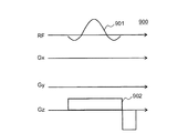
- FIG. 2 shows a pulse sequence 900 for exciting an arbitrary slice having a thickness in a one-dimensional direction.
- RF, Gx, Gy, and Gz indicate application timings of the RF pulse, the gradient magnetic field in the x-axis direction, the gradient magnetic field in the y-axis direction, and the gradient magnetic field in the z-axis direction, respectively.
- a slice selective gradient magnetic field 902 is applied in any one direction of Gx, Gy, and Gz.
- a case of applying in the Gz direction is illustrated. Thereby, a predetermined slice in which only the position in the z-axis direction is specified is selectively excited.
- a pulse sequence that realizes two-dimensional spatial selective excitation (hereinafter referred to as a 2DRF sequence), a k-space trajectory by the pulse sequence, and an excitation region will be described.
- Fig. 3 (a) shows the 2D RF sequence 200
- Fig. 3 (b) shows the k-space trajectory 220 based on the 2D RF sequence 200
- Figs. 3 (c) and 3 (d) show the regions excited by the 2D RF sequence 200 (main Lobes 231 and side lobes 232) are shown.
- Fig. 3 (a) shows only RF, Gx, and Gy as the 2D RF sequence 200.
- the 2DRF sequence 200 includes a two-dimensional selective excitation pulse (hereinafter referred to as 2DRF pulse) 201 and an oscillating gradient magnetic field pulse 202.
- 2DRF pulse a two-dimensional selective excitation pulse
- oscillating gradient magnetic field pulse 202 By these 2DRF pulse 201 and oscillating gradient magnetic field pulse 202, only a predetermined cylindrical region is selectively excited.
- the 2D RF pulse 201 and the oscillating gradient magnetic field pulse 202 are collectively referred to as a two-dimensional space selective excitation pulse 210.
- 2DRF pulse 201 is a pencil beam type excitation RF pulse for exciting a cylindrical region.
- F0 is the irradiation frequency of the 2D RF pulse 201.
- the oscillating gradient magnetic field pulse 202 has its k-space trajectory 220 in the Gx and Gy directions so that it has a spiral trajectory from the center of the k-space to the outside or the outside to the center. Applied.
- the frequency n of the oscillating gradient magnetic field pulse 202 is equal to the number of spiral turns (number of rotations) n of the k-space trajectory 220.
- G 0 is the maximum intensity of the oscillating gradient magnetic field pulse 202.
- the region excited by the 2DRF sequence 200 is the target excitation region (main lobe) 231 at the center of the xy plane and the non-target excitation at the outer concentric position.
- the lateral magnetization (signal intensity) of the side lobe 232 is smaller than that of the main lobe 231. It is assumed that the diameter of the main lobe 231 to be excited is X 0 and the diameter of the side lobe 232 is WX 0 .
- the respective excitation profiles in the x direction are shown in FIG. 3 (d).
- the vertical axis represents the signal intensity.
- the 3D RF sequence applies the two-dimensional spatial selective excitation pulse 210 including the 2D RF pulse 201 and the oscillating gradient magnetic field pulse 202 a plurality of times.
- the two-dimensional space selective excitation pulse 210 is applied with various application patterns by changing the intensity and frequency of the RF pulse and the vibration gradient magnetic field pulse in various ways.
- FIG. -3 3DRF sequences 300 (300-1, 300-2, 300, respectively) having different application patterns of the two-dimensional spatial selective excitation pulse 210 of this embodiment are shown in FIG. -3) is illustrated.
- the 3DRF sequence 300 includes a plurality of two-dimensional spatial selective excitation pulses 210 (hereinafter, in the 3DRF sequence, three-dimensional spatial selective excitation pulses 310). Called).
- Each three-dimensional space selective excitation pulse 310 includes a 3D RF pulse 301 which is a pencil beam type excitation RF pulse similar to the 2D RF pulse 201, and an oscillating gradient magnetic field pulse 302 similar to the oscillating gradient magnetic field pulse 202.
- each three-dimensional space selective excitation pulse 310 is sequentially called 310a, 310b, 310c, 310d, 310e, and the oscillating gradient magnetic field pulse applied in the x-axis direction (Gx direction) is 302x.
- the oscillating gradient magnetic field pulse applied in the y-axis direction (Gy direction) is referred to as 302y
- the oscillating gradient magnetic field pulse applied in the z-axis direction (Gz direction) is referred to as 302z.
- the oscillating gradient magnetic field pulse 302 in the uniaxial direction is a blip gradient magnetic field pulse.
- the oscillating gradient magnetic field pulses 302x and 302y are applied in the Gx direction and the Gy direction, and the blip gradient magnetic field pulse 302z is applied in the Gz direction.
- the application intensity of the 3D RF pulse 301 is changed according to a predetermined pattern.
- Fig. 4 (b) shows the k-space trajectory (first k-space trajectory) 320-1 by the 3D space selective excitation pulse 310 of the 3DRF sequence 300-1.
- the k-space trajectories by the respective three-dimensional spatial selective excitation pulses 310a, 310b, 310c, 310d, and 310e are indicated by 320a, 320b, 320c, 320d, and 320e, respectively.
- Each k-space trajectory 320a, 320b, 320c, 320d, 320e becomes a spiral trajectory on the kx-ky plane with different positions in the kz direction.
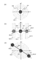
- FIGS. 5 (a), 5 (b) and 5 (c) show regions (main lobe 331 and side lobe 332) excited by the 3D RF sequence 300-1 shown in FIG. 4 (a).
- Reference numeral 339 denotes a positioning image.
- the voxel-shaped main lobe 331 and the ring-shaped side lobe 332-1 are excited by the 3D RF pulse 301, the oscillating gradient magnetic field pulses 302x and 302y, and the blip gradient magnetic field pulse 302z.
- side lobes 332-2 and 332-3 appearing at different positions in the z-axis direction with the same shape as 331 and 332-1 are also excited. That is, according to the 3DRF sequence 300-1, the first side lobe 332-1 appears concentrically with the main lobe 331 in the direction of the oscillating gradient magnetic field pulses 302x and 302y.
- the second side lobe 332-2 and the third side lobe 332-3 appear in the direction of the blip gradient magnetic field 302z (Z direction).
- the second side lobe 332-2 and the third side lobe 332-2 are excitation regions having the same shape as the main lobe 331 and the first side lobe 332-1, respectively, and only the center position in the z direction is present. Different.
- Two second side lobes 332-2 and third side lobes 332-3 appear at equidistant positions from the main lobe 331 in the blip gradient magnetic field 302z direction (Z direction).
- the application intensity of the 3DRF pulse 301 is all the same.
- the applied intensity of the oscillating gradient magnetic field pulse 302 gradually increases and decreases symmetrically in two directions, and is constant in the remaining one direction.
- Gx direction oscillating gradient magnetic field pulse 302x gradually increases its intensity
- Gy direction oscillating gradient magnetic field pulse 302y gradually decreases its intensity
- Gz direction oscillating gradient magnetic field pulse 302z has a constant intensity. Is illustrated.
- the k-space trajectory (second k-space trajectory) 320-2 by the 3D spatial selective excitation pulse 310 of the 3DRF sequence 300-2 is shown in FIG. 6 (b) and FIG. 6 (c).
- Each k-space trajectory 320a, 320b, 320c, 320d, 320e is a plane orthogonal to the kx-ky plane, and the intersection line with the kx-ky plane is on a different plane passing through the origin of the kx-ky plane, respectively. It becomes a spiral trajectory.
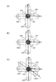
- FIGS. 7 (a), 7 (b) and 7 (c) The regions (main lobe 331 and side lobe 332) excited by this 3DRF sequence 300-2 are shown in FIGS. 7 (a), 7 (b) and 7 (c).
- the voxel-shaped main lobe 331 and the disk-shaped side lobe 332-1 are excited.
- side lobes 332-2 and 332-3 appearing at different positions in the z-axis direction with the same shape as 331 and 332-1 are also excited.
- the disk-shaped first side lobe 332-1 appears on the surface specified by the applied direction of the oscillating gradient magnetic field that is not applied at a constant intensity.
- the first side lobe 332-1 appears on the xy plane.
- the second side lobe 332-2 and the third side lobe 332-3 appear in the application direction (z direction) of the oscillating gradient magnetic field applied at a constant intensity.
- the second side lobe 332-2 and the third side lobe 332-2 are excitation regions having the same shape as the main lobe 331 and the first side lobe 332-1 and differ only in the center position in the Z-axis direction. .
- Two of the second side lobe 332-2 and the third side lobe 332-2 appear at positions equidistant from the main lobe 331 in the vibration gradient magnetic field application direction (z direction) applied at a constant intensity.
- the third side lobe 332-3 is omitted.
- the application intensity of the 3DRF pulse 301 is all the same.
- the oscillating gradient magnetic field pulse 302 (302x, 302y, 302z) is applied only in two directions.
- Fig. 8 (b) to Fig. 8 (d) show the k-space trajectory (third k-space trajectory) 320-3 by the 3D space selective excitation pulse 310 of the 3DRF sequence 300-3.
- Each k-space trajectory 320a, 320b, 320c becomes a spiral trajectory on the kz-kx plane, the ky-kx plane, and the kz-ky plane, respectively.
- FIGS. 9 (a), 9 (b) and 9 (c) The regions excited by this 3DRF sequence 300-3 are shown in FIGS. 9 (a), 9 (b) and 9 (c).
- the voxel-shaped main lobe 331 and the voxel-shaped side lobe 332-1 are excited.
- a cylindrical main lobe and a cylindrical side lobe similar to those in FIG. 3C are generated in the X, Y, and Z directions.
- a voxel-like region where a plurality of main lobes are superimposed is excited as a main lobe 331, and a cylinder-like region other than 331 and a voxel-like region where side lobes are superimposed are excited as side lobes 332-1. Is done.
- the 3D RF sequence 300 selectively excites a voxel-like region by applying a three-dimensional spatial selective excitation pulse 310 composed of a set of the 3D RF pulse 301 and the oscillating gradient magnetic field pulse 302 a plurality of times.
- the generation mode of the k-space trajectory 320 differs depending on the application pattern of the three-dimensional space selective excitation pulse 310.
- the generation position of the side lobe 332 is also different.
- each of the three k-space trajectories is generated by selecting the k-space trajectory so as to selectively excite only the target excitation region with high accuracy.
- a dimension space selective excitation pulse 310 is adjusted.
- the function of the control unit 120 of the present embodiment that realizes this will be described.
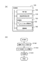
- FIG. 1 (b) is a functional block diagram of the control unit 120 of the present embodiment.
- control unit 120 of the present embodiment includes an accepting unit 130 that accepts input of imaging parameters and selection of a k-space trajectory from a user, and an excitation region display that displays an excitation region based on the selected k-space trajectory Unit 140, adjustment unit 150 that adjusts three-dimensional spatial selective excitation pulse 310 to selectively excite a target region, and imaging in accordance with an imaging sequence using adjusted three-dimensional spatial selective excitation pulse 310 An imaging unit 160.
- the adjustment unit 150 includes an excitation region adjustment unit 151 that reflects the adjustment for the position of the excitation region received from the user in the three-dimensional space selective excitation pulse 310, and an adjustment for the displacement of the excitation position due to device distortion.
- An apparatus distortion adjusting unit 152 that reflects the three-dimensional space selective excitation pulse 310.
- the accepting unit 130 accepts imaging parameters and designation of a k-space trajectory, and generates an imaging sequence used for actual imaging.
- a pulse sequence having an application pattern that realizes a user-selectable k-space trajectory is stored in advance in the storage unit in association with the k-space trajectory.
- the accepting unit 130 extracts a pulse sequence that realizes the k-space trajectory according to a user's designation, and generates an imaging sequence reflecting the imaging parameters.
- the designation is performed, for example, via an excitation area screen described later.
- a selectable k-space trajectory may be presented in a menu format so that the user can select it.
- the excitation region display unit 140 calculates the excitation region (main lobe 331 and side lobe 332) excited by the k-space trajectory selected by the user and displays it on the display unit 121.
- the display is updated every time the k-space trajectory is selected in the receiving unit 130.
- every time the excitation region adjustment unit 151 described later reflects the adjustment by the user in the three-dimensional space selective excitation pulse 310, the display of the excitation region is updated according to the adjustment.
- the screen on which the calculated main lobe 331 and side lobe 332 are displayed is referred to as an excitation area screen.
- the excitation area screen includes an excitation area (main lobe 331 and side lobe 332) display area, an end button for accepting the intention to end adjustment of the excitation area, and a selection area for accepting selection of the k-space trajectory.
- the accepting unit 130 accepts selection and change of the k-space trajectory from the user via this selection area.
- Excitation areas in the excitation area display area are, for example, FIG. 5 (a), FIG. 5 (b), FIG. 5 (c), FIG. 7 (a), FIG. 7 (b), FIG. 7 (c), FIG. Displayed as shown in a), FIG. 9 (b), and FIG. 9 (c).
- the display mode of the excitation region is two-dimensional. It may be a three-dimensional display as shown in FIGS. 5 (c), 7 (c), and 9 (c).
- the display mode of the main lobe 331 and the side lobe 332 is changed so that the user can easily grasp the position of the side lobe 332.
- the display mode is changed, for example, by changing the color or changing the pattern. Further, as shown in FIG. 5 (a), FIG. 5 (b), FIG. 7 (a), FIG. 7 (b), FIG. 9 (a), FIG. Also good.
- the excitation region adjustment unit 151 receives the adjustment of the excitation region from the user via the excitation region displayed on the display unit 121, and reflects the adjustment in the three-dimensional space selective excitation pulse 310.
- the accepted adjustments are, for example, the position, orientation, and size of each of the main lobe 331 and the side lobe 332, the relative distance 341 between the main lobe 331 and the side lobe 332, and the relative distance 342 between the side lobes 332 (FIG. ), FIG. 5 (a)-(c), FIG. 7 (a)-(c), and FIG. 9 (a)-(c)).
- the relative distances 341 and 342 are distances between peak positions, respectively.
- the excitation region adjustment unit 151 adjusts the three-dimensional space selective excitation pulse 310 so as to realize the adjusted main lobe 331 and side lobe 332.
- the three-dimensional space selective excitation pulse 310 is adjusted so as to realize the excitation region displayed on the excitation region screen when the end button is pressed.
- the number of applications of the three-dimensional space selective excitation pulse 310 and the number of rotations (vibration frequency) of the oscillating gradient magnetic field pulse 302 are adjusted according to changes in the relative distances 341 and 342.
- the rotation speed (frequency) of each oscillating gradient magnetic field pulse 302 is changed.
- the position of the side lobe 332 approaches the main lobe 331 as the rotational speed (frequency) of the oscillating gradient magnetic field pulse 302 is decreased. Therefore, when the relative distance 341 becomes longer, the rotation number (frequency) of the oscillating gradient magnetic field pulse 302 is increased.
- the number of three-dimensional space selective excitation pulses 310 to be applied is changed. Specifically, when the relative distance 342 is increased, the number of three-dimensional spatial selective excitation pulses 310 to be applied is increased. In the 3D RF sequences 300-1 and 300-2, the main lobe 331 is excited by being divided by a plurality of RF pulses (3D RF pulse 301). For this reason, when the number of applied three-dimensional space selective excitation pulses 310 is increased, the FA of the side lobe 332-1 decreases. Therefore, also when the FA of the side lobe 332-1 is lowered, the number of three-dimensional spatial selective excitation pulses 310 to be applied is increased.
- the apparatus distortion adjustment unit 152 reflects the adjustment of the displacement of the excitation position due to the apparatus distortion in the three-dimensional space selective excitation pulse 310.
- the device distortion adjustment unit 152 performs optimization processing similar to the conventional optimization processing in the 2D RF sequence 200 on each three-dimensional spatial selective excitation pulse 310 to optimize the irradiation frequency, application time, and rotation speed.
- the conventional optimization process uses, for example, the technique disclosed in Patent Document 1 or Patent Document 3 described above.
- the static magnetic field inhomogeneity in the region of interest is measured, and the resonance frequency of magnetization obtained from the measurement result is set as the irradiation frequency of the 3D RF pulse 301.
- the optimum application time of the 3D RF pulse 301 and the rotation speed of the oscillating gradient magnetic field pulse 302 are obtained while changing the coefficient for determining the cylinder diameter of the excitation region and the time difference for determining the offset position.
- an optimization process similar to the optimization process for the 2D RF sequence 200 is performed on one three-dimensional spatial selective excitation pulse 310, and an adjustment value for the obtained three-dimensional spatial selective excitation pulse 310 is set to another
- the present invention may also be applied to the three-dimensional space selective excitation pulse 310. Thereby, the time required for optimization adjustment can be shortened.
- the device distortion adjustment unit 152 uses an excitation profile obtained from a signal measured according to a predetermined prescan sequence, and adjusts the intensity adjustment value (intensity adjustment value) C W of the oscillating gradient magnetic field pulse 302 and the start phase of the 3D RF pulse 301.
- the adjustment value (referred to as a position adjustment value or a start phase adjustment value) CP is calculated and reflected in each three-dimensional space selective excitation pulse 310.
- the excitation profile is acquired by performing Fourier transform on a signal acquired according to a predetermined prescan sequence.
- the pre-scan sequence to be used is stored in advance in the storage unit according to the k-space trajectory used for imaging.
- the apparatus distortion adjustment unit 152 extracts a pre-scan sequence from the storage unit according to the k-space trajectory selected by the user.
- FIG. 10 (a) shows a pre-scan sequence 400 in the case of performing main imaging with the 3DRF sequence 300-1 shown in FIG. 4 (a).
- the adjustment value in the blip direction (z direction) is calculated.
- the magnetic field center (RF pulse 401 and oscillating gradient magnetic field pulse 402) is generated by a three-dimensional spatial selective excitation pulse (RF pulse 401 and oscillating gradient magnetic field pulse 402) having the same configuration as the sequence 300-1 shown in FIG.
- the obtained signal 404 has a plurality of peaks as shown in FIG.
- FIG. 10B shows the excitation profile in the z direction obtained at this time.
- device distortion adjustment unit 152 first obtains the half width WZ 1 excitation profile in the z direction of the main lobe 431. Note that the half width WZ 1 is measured and acquired by scanning the obtained excitation profile, as described in Patent Document 3, for example. Then, the calculation of the oscillating gradient magnetic field pulse 302z in the z direction, the intensity adjustment value C WZ using the half-width WZ 1.
- This intensity adjustment value C WZ is expressed by the following expression (1), where the width in the z direction of the main lobe 331 set by the user on the excitation area screen is WZ 0 .
- the start phase adjustment value C PZ in the z direction may be calculated from the phase difference at the signal center between the acquired multiple-peak signals 404, or as described in Patent Document 2, It may be obtained by dividing the position shift amount by the peak interval of each RF pulse.
- the apparatus distortion adjustment unit 152 reflects the calculated oscillating gradient magnetic field intensity adjustment value C WZ and the start phase adjustment value CPZ in the three-dimensional spatial selective excitation pulse 310 of the imaging sequence. Specifically, the oscillating gradient magnetic field intensity adjustment value C WZ is multiplied by the intensity Gz 0 of the oscillating gradient magnetic field pulse 302z in the z direction, and the start phase adjustment value C PZ in the z direction is set to the start phase of each 3D RF pulse 301. Add to the increment value.
- the intensity (Gz 0 ⁇ C WZ ) of the oscillating gradient magnetic field pulse 302z after adjustment exceeds the maximum value of the gradient magnetic field intensity that can be applied by the MRI apparatus 100, it is not the adjusted value but the MRI
- the maximum value that can be applied by the device 100 is used.
- it may be configured to calculate the excitation region based on the vibration gradient magnetic field pulse intensity to be used and display it on the display unit 121.
- the radius of the side lobe 332 (the relative distance between the main lobe 331 and the side lobe 332) 341 is isotropic in the xy direction, so only encoding in the z direction is possible. Can determine the excitation profile in the z direction.
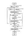
- FIG. 11 is a processing flow of the imaging process of the present embodiment. This process starts upon receiving a start instruction from the user.
- the receiving unit 130 receives an imaging parameter input by the user (step S1101).
- the accepting unit 130 accepts selection of a k-space trajectory (step S1102).
- the excitation area display unit 140 When the k-space trajectory is selected, the excitation area display unit 140 generates an excitation area screen and displays the excitation area of the accepted k-space trajectory (step S1103).
- the excitation region adjustment unit 151 When receiving the adjustment from the user via the excitation region screen (step S1104), the excitation region adjustment unit 151 reflects the received adjustment on the three-dimensional space selective excitation pulse 310 (step S1105). When the adjustment is reflected in the three-dimensional spatial selective excitation pulse 310, the excitation region display unit 140 recalculates the excitation region by the three-dimensional spatial selective excitation pulse 310 after the reflection, and updates the excitation region on the excitation region screen ( Step S1106).
- step S1107 when the accepting unit 130 accepts an instruction to change the k-space trajectory from the user on the excitation area screen (step S1107), the process returns to step S1102, accepts the selected k-space trajectory, and repeats the process.
- step S1108 the process of accepting adjustment and changing the k-space trajectory continues until an end instruction is received from the user on the excitation area screen (step S1108).
- the apparatus distortion adjustment unit 152 performs an excitation position adjustment process (apparatus distortion adjustment process) due to apparatus distortion (step S1109).
- the flow of adjustment processing by the apparatus distortion adjustment unit 152 will be described later.
- the imaging unit 160 performs the main imaging according to the imaging sequence by the three-dimensional space selective excitation pulse 310 in which the adjustment is reflected (step S1110), and ends the process.
- the k-space trajectory to be used may be determined while viewing each excitation region, and then the determined excitation region of the k-space trajectory may be adjusted.
- the excitation area screen includes a confirmation button for accepting the intention of confirming the k-space trajectory used for imaging.
- Fig. 12 shows the flow of imaging processing in this case.
- the accepting unit 130 accepts input of imaging parameters from the user (step S1201).
- the k-space trajectory used for imaging is determined (step S1202).
- the accepting unit 130 accepts selection of the k-space trajectory
- the excitation region display unit 140 generates an excitation region screen and displays the accepted excitation region of the k-space trajectory. This is repeated every time the accepting unit 130 accepts the k-space trajectory until the press of the confirm button is accepted.
- the selection is stored in advance in the storage unit.
- the three-dimensional spatial selective excitation pulse 310 is applied from among a plurality of 3D RF sequences (k-space trajectories) having different application patterns.
- the adjustment unit 150 adjusts the determined three-dimensional spatial selective excitation pulse 310 of the k-space trajectory (step S1203).
- adjustment is performed so that the target region is selectively excited.
- two types of adjustment are performed: adjustment of the excitation position according to the user's instruction and adjustment for the apparatus distortion.
- the imaging unit 160 performs the main imaging (step S1204).
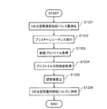
- FIG. 13 is a processing flow of apparatus distortion adjustment processing of the present embodiment.
- the apparatus distortion adjustment unit 152 performs an optimization process for optimizing each three-dimensional space selective excitation pulse 310 (step S1301).
- the optimization processing is performed by the above method (conventional optimization processing of the two-dimensional spatial selective excitation pulse 210 of the 2D RF sequence).
- the apparatus distortion adjustment unit 152 selects a pre-scan sequence corresponding to the k-space trajectory and executes it to acquire a signal (step S1302). Then, an excitation profile is acquired from the obtained signal (step S1303).
- the characteristic value of the excitation profile is acquired (step S1304).
- the selected k-space trajectory is the first k-space trajectory 320-1 shown in FIG. 4 (b) and the excitation profile is obtained by the pre-scan sequence 400 shown in FIG.
- the characteristic values are the half width WZ 1 in the z direction of the excitation profile of the main lobe 431, the distance Z 1 in the z direction between the peak position of the excitation profile of the main lobe 431 and the magnetic field center, A distance Z 0 in the z direction between the peak position of the excitation profile of the main lobe 431 and the peak position of the excitation profile of the side lobe 432.
- the MRI apparatus 100 is an MRI apparatus 100 including the control unit 120 that controls each part of the apparatus according to an imaging sequence generated by a preset imaging parameter and a predetermined pulse sequence.
- the pulse sequence includes a multidimensional spatial selective excitation pulse composed of a two-dimensional selective excitation pulse having a main lobe and a side lobe and an oscillating gradient magnetic field pulse, and the control unit 120 defines a target region as the main lobe.
- Includes an adjustment unit 150 that adjusts the multi-dimensional spatial selective excitation pulse so as to be selectively excited.
- the pulse sequence may be a three-dimensional selective excitation sequence 300 that applies a plurality of the multidimensional spatial selective excitation pulses.
- the control unit 120 includes a receiving unit 130 that accepts a user's selection from a plurality of three-dimensional selective excitation sequences 300 having different application patterns of the multidimensional spatial selective excitation pulse, and the user performs the three-dimensional selective excitation sequence 300.
- An excitation region display unit 140 that displays the excitation region of the main lobe and the side lobe of the three-dimensional selective excitation sequence 300 for each selection may be further provided.
- the excitation area display unit 140 may display the excitation area on the positioning image.
- the adjustment unit 150 may include an excitation region adjustment unit 151 that receives an adjustment of an excitation region from the user on the displayed excitation region and reflects the adjustment in the multidimensional spatial selective excitation pulse.
- the adjustment unit 150 includes a device distortion adjustment unit 152 that adjusts the multidimensional space selective excitation pulse so as to eliminate the influence of device distortion based on an excitation profile based on a signal obtained by a predetermined prescan, and the device
- the distortion adjustment unit 152 calculates an intensity adjustment value of the oscillating gradient magnetic field pulse 202 and a start phase adjustment value of each two-dimensional selective excitation pulse 201 from the excitation profile, and uses the calculated intensity adjustment value and start phase adjustment value.
- the multidimensional spatial selective excitation pulse may be adjusted.
- the intensity adjustment value is calculated as a ratio of a half-value width of the excitation profile of the main lobe and a width in the same direction of the target excitation region, and the start phase adjustment value is calculated by calculating the center of the excitation profile of the main lobe and the magnetic field. It may be calculated as a ratio of the distance between the center and the distance between the center of the excitation profile of the main lobe and the center of the excitation profile of the side lobe.
- the excitation region adjustment unit 151 adjusts the frequency of the oscillating gradient magnetic field pulse so as to increase as the relative distance between the main lobe and the side lobe increases, and increases as the relative distance between the side lobes increases.
- the number of applied multidimensional space selective excitation pulses may be adjusted.
- the excitation region is displayed in an easy-to-understand manner even for imaging using a 3DRF sequence.
- the user can select a k-space trajectory (application pattern of the three-dimensional spatial selective excitation pulse 310) in which a position having no problem in the inspection is excited.
- the user can adjust the size and position of the main lobe and side lobe while viewing this display. The adjustment result is automatically reflected in the imaging sequence.
- the user can easily adjust the positional relationship between the imaging range, the imaging target, the main lobe and the side lobe, It can be a position where there is no problem in the inspection. Therefore, according to the present embodiment, excitation of a non-target region due to a side lobe can be easily avoided even in imaging using a 3DRF sequence.
- the displacement of the excitation position due to the apparatus distortion is adjusted according to the k-space trajectory (application pattern of the three-dimensional space selective excitation pulse). Therefore, even in a 3D RF sequence with a longer application time of a three-dimensional spatial selective excitation pulse, it is possible to reduce the displacement of the excitation position due to device distortion, as in the case of imaging with a 2D RF sequence. That is, according to the present embodiment, the target region can be stably excited even with the 3DRF sequence.
- the present embodiment even in the two-dimensional spatial selective excitation method or the three-dimensional spatial selective excitation method, only a target region can be selectively selected with high accuracy without imposing a burden on the user. This reduces the number of inspection failures and improves the quality of the resulting image.
- the user selects an imaging sequence (k-space trajectory) used for imaging.
- the system may automatically determine based on the imaging conditions set by the user.
- the control unit 120 further includes a sequence determination unit 170 as shown in FIG. 14 (a).
- the sequence determination unit 170 determines a three-dimensional selective excitation sequence 300 optimum for the imaging condition from a plurality of three-dimensional selective excitation sequences 300 having different application patterns of the multidimensional spatial selective excitation pulse based on the imaging condition. .
- the side lobe generated in the direction in which the number of trajectories increases or decreases according to the number of times of application is most likely to approach the main lobe.
- the side lobe 332-2 in the z direction shown in FIG. 5 (b) is likely to appear closest to the main lobe 331.
- the sequence determination unit 170 selects a pulse sequence indicating a k-space trajectory in which the readout direction of the imaging sequence is a direction in which the number of trajectories increases or decreases according to the number of times of application (a direction in which side lobes are most likely to be closest).
- the accepting unit 130 accepts only the imaging parameters.
- the system may not be automatically determined, but may be configured to present the encoding direction and k-space trajectory recommended by the system to the operator's settings and accept the selection from the operator.
- the control unit 120 determines at least one of the encoding direction and the k-space trajectory as a recommended change plan, presents it to the operator, and designates it from the operator.
- a change proposal presenting unit 180 is further provided.
- the change proposal presenting unit 180 analyzes the received imaging condition and the three-dimensional selective excitation sequence 300, and creates and presents the proposed imaging condition or the proposed change of the three-dimensional selective excitation sequence 300. At this time, the three-dimensional selective excitation sequence 300 used for the imaging and the proposed change are selected from a plurality of three-dimensional selective excitation sequences 300 having different application patterns of the multidimensional spatial selective excitation pulse held in advance.
- the change proposal presenting unit 180 analyzes the imaging condition and k-space trajectory set by the user, and the direction in which the number of trajectories increases or decreases according to the number of times of application (the direction in which the side lobe tends to be closest) is the slice direction or phase.
- the encoding direction is set (different from the lead-out encoding direction)
- the following change proposal is generated and displayed on the display unit 121 to the user.
- the k-space trajectory is changed to a k-space trajectory in which the readout direction of the imaging condition set by the user is a direction in which the number of trajectories increases or decreases according to the number of times of application (a direction in which side lobes are most likely to be closest).
- the accepting unit 130 accepts a selection made by the user from the change plans presented by the change plan presenting unit 180, and determines the imaging parameters and k-space trajectory used for imaging based on the accepted change plan.
- the excitation area display unit 140 calculates and displays the excitation area according to the determined imaging parameter and k-space trajectory.
- the adjustment unit 150 also adjusts the three-dimensional space selective excitation pulse 310 determined by the determined imaging parameter and k-space trajectory.
- the configuration of the MRI apparatus 100 of this embodiment is basically the same as that of the first embodiment.
- the two-dimensional space selective excitation pulse is further provided with a second 2DRF pulse (hereinafter referred to as a sub-2DRF pulse), and side lobes are appropriately suppressed by the sub-2DRF pulse. Therefore, in this embodiment, the pulse sequence used for imaging is different.
- the control unit 120 of the present embodiment includes a receiving unit 130 that receives an input of imaging parameters from a user, and a two-dimensional space selective excitation so as to selectively excite a target region.
- An adjustment unit 150 that adjusts a pulse, and an imaging unit 160 that performs imaging according to an imaging sequence using the adjusted two-dimensional spatial selective excitation pulse.
- the adjustment unit 150 according to the present embodiment includes a sub-pulse adjustment unit 153 that adjusts the sub 2DRF pulse so as to cancel the side lobe of the 2DRF pulse.
- the configuration having the same name as the first embodiment basically has the same function.
- the present embodiment will be described focusing on the configuration different from the first embodiment.
- FIG. 16 (a) is an example of the 2DRF sequence 500 of the present embodiment.
- Gx and Gy are shown as gradient magnetic field application axes.
- the 2DRF sequence 500 of this embodiment includes a 2DRF pulse 501, a second 2DRF pulse (hereinafter referred to as a sub 2DRF pulse) 501s, and an oscillating gradient magnetic field pulse 502.
- the 2D RF pulse 501, the second 2D RF pulse 501s, and the oscillating gradient magnetic field pulse 502 are collectively referred to as a two-dimensional space selective excitation pulse 510.
- the 2DRF pulse 501 is shown on the RF1 axis
- the sub 2DRF pulse 501s is shown on the RF2 axis.
- the 2DRF pulse 501 is an RF pulse of pencil beam type excitation similar to the 2DRF pulse of the first embodiment.
- the irradiation frequency is F0.
- the application start phase is 90 degrees.
- the sub 2D RF pulse 501s has an application start phase of ⁇ 90 degrees and an irradiation frequency of F0 + ⁇ F.
- the main lobe by the sub 2DRF pulse 501s is concentric. ⁇ F is determined so that the main lobe is in the same position as the side lobe by the 2DRF pulse 501. The determination method will be described later.
- G 0 the intensity of the oscillating gradient magnetic field pulse 202 of 2DRF sequence 200 described in the first embodiment, when the frequency is n, the intensity of the oscillating gradient magnetic field pulse 502 2G 0, frequency and n / 2 To do.
- the two-dimensional spatial selective excitation pulse 210 of the 2D RF sequence 200 described in the first embodiment (the irradiation frequency F0 of the 2D RF pulse 201, the maximum intensity G 0 of the oscillating gradient magnetic field pulse 202).
- 2-dimensional space selective excitation pulse 510 of 2DRF sequence 500 of this embodiment When the diameter of the main lobe 531 by the 2DRF pulse 501 is X 1 and the diameter of the side lobe 532 is WX 1 , the following equations (3) and (4) are established.
- the scanning speed of the k-space is constant, the sub 2DRF pulse 501s, TBW (Time Band width) of the TBW 1, Duration T, as described above, the radiation frequency F0 + [Delta] F, the application start phase -90
- the main lobe by the sub 2D RF pulse 501s is concentric, and the diameter is represented by 4X 0 T ⁇ F / TBW 1 .
- the excitation profile s of the main lobe 531s by the sub 2D RF pulse 501s becomes as shown in FIG.
- the reason why the direction is opposite to that of the 2DRF pulse 501 is that the start phase of the sub 2DRF pulse 501s is shifted from the start phase of the 2DRF pulse 501 by 180 degrees.
- ⁇ F is determined so that the diameter WX 1 of the side lobe 532 by the 2DRF pulse 501 is equal to the diameter 4X 0 T ⁇ F / TBW 1 of the main lobe 531s of the sub 2DRF pulse 501s, as shown in FIG.
- the side lobe 532 by the 2DRF pulse 501 and the main lobe 531s of the sub 2DRF pulse 501s are at the same position.
- ⁇ F is determined so as to satisfy the following expression (6) by modifying the following expression (5).
- WX 1 4X 0 T ⁇ F / TBW 1 ...
- ⁇ F WX 0 TBW 1 / (8X 0 T) ⁇ ⁇ ⁇ (6)
- the sub-pulse adjustment unit 153 of the present embodiment first optimizes the 2D RF pulse 501 and the oscillating gradient magnetic field pulse 502 by the same method as the optimization method of the first embodiment, and then the side lobe 532 and the main lobe 531s.
- the sub 2D RF pulse 501s is optimized so that the diameter and the intensity of each match. Note that the amount of deviation ⁇ F of the irradiation frequency of the sub 2DRF pulse 501s from the 2DRF pulse 501 is determined by the above method.
- FIG. 17 is a processing flow of the sub-pulse adjustment processing of the present embodiment.
- optimization processing of the 2D RF pulse 501 and the oscillating gradient magnetic field pulse 502 in the two-dimensional space selective excitation pulse 510 is performed by the same method as in step S1301 of the first embodiment (step S1401).
- step S1401 optimization processing of the 2D RF pulse 501 and the oscillating gradient magnetic field pulse 502 in the two-dimensional space selective excitation pulse 510 is performed by the same method as in step S1301 of the first embodiment (step S1401).
- only the 2D RF pulse 501 is irradiated as an RF pulse, and optimization is performed.
- the signal Sig.1 by the 2DRF pulse 501 is acquired (step S1402).
- the case of applying in the Gx and Gy directions is illustrated.
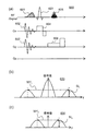
- a slice selection type 180 ° pulse 603 is applied in a cross section parallel to the axial direction of the pencil beam. Here, it is applied together with the slice selective gradient magnetic field pulse 604 in the x direction.
- a readout gradient magnetic field pulse 606 is applied in a direction perpendicular to the axial direction of the pencil beam and parallel to a slice plane of 180 ° (the y direction in FIG. 18A) to obtain a signal 605.
- the signal Sig.2 based on the sub 2D RF pulse 501s is acquired by the same method as in step S1302 (step S1403).
- the irradiation frequency of the pulse 601 is F0 + ⁇ F.
- Step S1404 Fourier transform of Sig.1 and Sig.2 respectively to obtain the excitation profile 620 in the diameter direction (y direction) of the pencil beam of the 2DRF pulse 501 and the excitation profile 630 in the concentric diameter direction (y direction) of the sub 2DRF pulse 501s.
- the excitation profiles 620 and 630 obtained at this time are shown in FIGS. 18 (b) and 18 (c), respectively.
- 2DRF pulses can be optimized even when two types of frequencies are output simultaneously. Even if there is a difference between the two irradiation systems, the excitation position can be accurately controlled.
- FIG. 15B is a process flow of the imaging process of the present embodiment.
- the receiving unit 130 receives an input of imaging parameters from the user (step S1501).
- the sub-pulse adjustment unit 153 optimizes the 2DRF pulse 501 and the oscillating gradient magnetic field pulse 502 and adjusts the sub-2DRF pulse 501s by the above method (step S1502).
- the application intensity and irradiation frequency of the sub 2DRF pulse 501s are adjusted so that the main lobe by the sub 2DRF pulse 501s cancels the side lobe by the 2DRF pulse 501.
- the imaging unit 160 performs main imaging (step S1503).
- each three-dimensional spatial selective excitation pulse 310 includes the sub 2DRF pulse 501s.
- the apparatus distortion adjustment process of the first embodiment is executed, and the 3D RF pulse 301 and the oscillating gradient magnetic field pulse 302 are optimized and adjusted.
- the sub pulse adjustment unit 153 adjusts the sub 2D RF pulse 501s of each three-dimensional space selective excitation pulse 310 by the above method.
- the excitation region adjustment unit 151 may be provided and the excitation region adjustment process may be performed as in the first embodiment. Further, as in the first embodiment, the reception unit 130 and the excitation region display unit 140 may be configured to receive selection of a desired k-space trajectory.
- the sequence determination unit 170 or the change plan presentation unit 180 may be provided as in the first embodiment.
- the MRI apparatus 100 of the present embodiment is an MRI apparatus 100 including a control unit that controls each part of the apparatus in accordance with an imaging sequence generated by a preset imaging parameter and a predetermined pulse sequence.
- the pulse sequence includes a multidimensional spatial selective excitation pulse composed of a two-dimensional selective excitation pulse 501 having a main lobe and a side lobe and an oscillating gradient magnetic field pulse 502, and the control unit 120 sets the target region as the main region.
- An adjustment unit 150 is provided for adjusting the multidimensional spatial selective excitation pulse so that the lobe is selectively excited.
- the multidimensional spatial selective excitation pulse further includes a sub two-dimensional selective excitation pulse 501s applied together with the two-dimensional selective excitation pulse 501, and the adjustment unit 150 includes a main lobe generated by the sub two-dimensional selective excitation pulse 501s.
- the adjustment unit 150 includes a main lobe generated by the sub two-dimensional selective excitation pulse 501s.
- the start phase of the sub two-dimensional selective excitation pulse 501s may be 180 degrees different from the start phase of the two-dimensional selective excitation pulse.
- the frequency of the oscillating gradient magnetic field pulse 502 may be smaller than the frequency of the oscillating gradient magnetic field pulse 202 of the multidimensional spatial selective excitation pulse that does not include the sub two-dimensional selective excitation pulse and obtains the same main lobe. .
- the side lobe due to the 2DRF pulse can be canceled by the main lobe due to the sub 2DRF pulse.
- excitation of a non-target region by a side lobe can be easily avoided without imposing a burden on the user, regardless of whether imaging is performed using either a 2DRF sequence or a 3DRF sequence. Thereby, the influence which a side lobe has on image quality can be suppressed.
- the displacement of the excitation position due to the apparatus distortion can be reduced, and the target region can be excited stably. For this reason, it becomes excitation different from the objective and the case where a test fails can be reduced. Further, even in the acquired image, artifacts due to signals in the non-target region can be reduced, and the image quality is improved.
- a pencil beam type RF pulse that excites only a cylindrical region is used.
- a gradient magnetic field (oscillating gradient magnetic field) pulse is applied so as to take a spiral locus from the center of the k space to the outside or from the outside to the center. Therefore, the application time of the two-dimensional space selective excitation pulse becomes long.
- the application time becomes longer.
- the size of the main lobe is made constant and the rotation speed of the k space is halved.
- side lobes are generated in addition to the main lobe.
- the application time can be reduced by half, but the side lobe radius can also be halved.
- the side lobe radius becomes small and approaches the main lobe, the side lobe may be superimposed on the imaging region.
- Non-Patent Document 3 a method of creating the optimum and shortest RF pulse irradiation waveform from the irradiation sensitivity distribution, k-space trajectory, and target excitation profile of the transmission coil 104 of multiple channels is known.
- the sensitivity distribution of the transmission coil 104 is used to create the RF pulse waveform, non-uniform irradiation occurs when a subject-dependent sensitivity distribution change occurs. Further, it is necessary to change the RF waveform according to the pattern of the transmission coil 104, and the system configuration becomes very complicated.
- the rotation speed of the k space can be reduced while keeping the diameter of the main lobe constant.
- the sensitivity distribution of the transmission coil 104 is not used. Therefore, as described above, the inspection time can be shortened in the present embodiment without the non-uniform irradiation caused by using the sensitivity distribution and the complicated system configuration.
- the influence of the side lobe can be realized without adjustment from the user and by reducing the measurement time.
- Duration can be shortened without changing the diameter of the side lobe and without performing complicated calculation using the irradiation sensitivity distribution.
- the frequency of the oscillating gradient magnetic field pulse 502 is half that of the first embodiment, but the frequency of the oscillating gradient magnetic field pulse 502 is not limited to this. It is only necessary that the side lobe does not overlap the main lobe.
- MRI apparatus 101 subject, 102 static magnetic field generating magnet, 103 gradient magnetic field coil, 104 transmission coil, 105 reception coil, 106 gradient magnetic field power supply, 106 signal detection unit, 107 RF transmission unit, 108 signal detection unit, 109 signal processing Unit, 110 sequencer, 110 measurement control unit, 111 bed, 120 control unit, 121 display unit, 122 operation unit, 130 reception unit, 140 excitation region display unit, 150 adjustment unit, 151 excitation region adjustment unit, 152 device distortion adjustment unit , 153 sub-pulse adjustment unit, 160 imaging unit, 170 sequence determination unit, 180 change plan presentation unit, 200 2DRF sequence, 201 2DRF pulse, 202 vibration gradient magnetic field pulse, 210 two-dimensional spatial selective excitation pulse, 220 k-space trajectory, 231 main Lobe, 232 side lobe, 300 3DRF sequence, 300 3D selective excitation sequence, 301 3DRF pulse, 302 oscillating gradient magnetic field pulse, 302x oscillating gradient magnetic field Luz, 302y oscillating gradient magnetic
Landscapes
- Physics & Mathematics (AREA)
- General Physics & Mathematics (AREA)
- Condensed Matter Physics & Semiconductors (AREA)
- High Energy & Nuclear Physics (AREA)
- Engineering & Computer Science (AREA)
- Signal Processing (AREA)
- Optics & Photonics (AREA)
- Spectroscopy & Molecular Physics (AREA)
- Health & Medical Sciences (AREA)
- Nuclear Medicine, Radiotherapy & Molecular Imaging (AREA)
- Radiology & Medical Imaging (AREA)
- General Health & Medical Sciences (AREA)
- Magnetic Resonance Imaging Apparatus (AREA)
- Life Sciences & Earth Sciences (AREA)
- Pathology (AREA)
- Biomedical Technology (AREA)
- Heart & Thoracic Surgery (AREA)
- Medical Informatics (AREA)
- Molecular Biology (AREA)
- Surgery (AREA)
- Animal Behavior & Ethology (AREA)
- Public Health (AREA)
- Veterinary Medicine (AREA)
- Biophysics (AREA)
Abstract
Description
以下、本発明を適用する第一の実施形態について説明する。以下、本発明の実施形態を説明するための全図において、同一機能を有するものは同一符号を付し、その繰り返しの説明は省略する。
また、取得したメインローブ431のz方向の励起プロファイルの中心と磁場中心との距離Z1と、メインローブ431のz方向の励起プロファイルとサイドローブ432のz方向の励起プロファイルとの距離Z0とを用い、z方向の開始位相調整値CPZを以下の式(2)で算出する。
なお、z方向の開始位相調整値CPZは、取得した複数ピークの信号404間の、信号中心の位相差から算出してもよいし、特許文献2に記載されているように、Z方向の位置のずれ量を各RFパルスのピーク間隔で除算することにより得ても良い。
なお、この場合は、受付部130では、撮像パラメータのみ受け付ける。
なお、3)の選択肢によれば、操作者が意図しない領域が励起されることによる、検査の失敗を防止できる。
次に、本発明を適用する第二の実施形態を説明する。第一の実施形態では、励起領域の位置を調整することにより目的外領域からの信号の流入を防ぐ。これに対し、本実施形態では、サイドローブ自体を抑制することにより、目的外領域からの信号の流入を防ぐ。
ペンシルビーム型のRFパルスを用いるシーケンスで、メインローブのサイズを一定に保ちながら振動傾斜磁場パルスの振動数を半分にすると、サイドローブの半径が半分になることが知られている(例えば、非特許文献2参照)。
WX1=WX0/2・・・(4)
この2DRFパルス501によるメインローブ531のx方向の励起プロファイルおよびサイドローブ532の同励起プロファイルを、図16(c)に示す。
これにより、サブ2DRFパルス501sによるメインローブ531sの励起プロファイルsは、図16(c)に示すものとなる。2DRFパルス501によるものと逆向きになるのは、サブ2DRFパルス501sの開始位相が、2DRFパルス501の開始位相から180度ずらしてあるためである。
WX1=4X0TΔF/TBW1・・・(5)
ΔF=WX0TBW1/(8X0T)・・・(6)
次に、本実施形態のサブパルス調整部153によるサブ2DRFパルスの調整処理について説明する。
CF2=WY1/WY2・・・(7)
CA2=SI1/SI2・・・(8)
そして、算出した周波数調整値CF2および強度調整値CA2を、サブ2DRFパルス501sに反映する(ステップS1407)。具体的には、周波数調整値CF2を、ΔFに乗算し、サブ2DRFパルス501sの照射周波数を(F0+CF2ΔF)とする。また、強度調整値CA2をサブ2DRFパルス501sの強度Amp2に乗算し、サブ2DRFパルス501sの強度を(CA2Amp2)とする。
Claims (15)
- 予め設定される撮像パラメータと予め定めたパルスシーケンスとにより生成される撮像シーケンスに従って装置各部を制御する制御部を備える磁気共鳴イメージング装置であって、
前記パルスシーケンスは、印加するパルスとして、メインローブおよびサイドローブを有する2次元選択励起パルスと、振動傾斜磁場パルスとからなる多次元空間選択励起パルスを含み、
前記制御部は、前記メインローブが目的とする領域を選択的に励起するよう前記多次元空間選択励起パルスを調整する調整部を備えること
を特徴とする磁気共鳴イメージング装置。 - 請求項1記載の磁気共鳴イメージング装置であって、
前記パルスシーケンスは、前記多次元空間選択励起パルスを複数印加する3次元選択励起シーケンスであること
を特徴とする磁気共鳴イメージング装置。 - 請求項2記載の磁気共鳴イメージング装置であって、
前記制御部は、
前記多次元空間選択励起パルスの印加パターンの異なる複数の前記3次元選択励起シーケンスの中から、ユーザの選択を受け付ける受付部と、
ユーザが前記3次元選択励起シーケンスを選択する毎に、当該3次元選択励起シーケンスの前記メインローブおよび前記サイドローブの励起領域を表示する励起領域表示部と、をさらに備えること
を特徴とする磁気共鳴イメージング装置。 - 請求項1記載の磁気共鳴イメージング装置であって、
前記制御部は、前記メインローブおよび前記サイドローブの励起領域を表示する励起領域表示部をさらに備え、
前記調整部は、表示される前記励起領域上でユーザから励起領域の調整を受け付け、当該調整を、前記多次元空間選択励起パルスに反映する励起領域調整部を備えること
を特徴とする磁気共鳴イメージング装置。 - 請求項1記載の磁気共鳴イメージング装置であって、
前記調整部は、予め定めたプリスキャンで得た信号による励起プロファイルに基づいて装置歪みによる影響を除くよう前記多次元空間選択励起パルスを調整する装置歪み調整部を備え、
前記装置歪み調整部は、前記励起プロファイルから前記振動傾斜磁場パルスの強度調整値と前記各2次元選択励起パルスの開始位相調整値とを算出し、算出した強度調整値および開始位相調整値により前記多次元空間選択励起パルスを調整すること
を特徴とする磁気共鳴イメージング装置。 - 請求項1乃至5のいずれか一項記載の磁気共鳴イメージング装置であって、
前記多次元空間選択励起パルスは、前記2次元選択励起パルスとともに印加するサブ2次元選択励起パルスをさらに含み、
前記調整部は、前記サブ2次元選択励起パルスによるメインローブが、前記2次元選択励起パルスによるサイドローブを打ち消すよう、当該サブ2次元選択励起パルスの印加強度および照射周波数を決定するサブパルス調整部を備えること
を特徴とする磁気共鳴イメージング装置。 - 請求項6記載の磁気共鳴イメージング装置であって、
前記サブ2次元選択励起パルスの開始位相は、前記2次元選択励起パルスの開始位相と180度異なること
を特徴とする磁気共鳴イメージング装置。 - 請求項6記載の磁気共鳴イメージング装置であって、
前記振動傾斜磁場パルスの振動数は、同じメインローブを得る、前記サブ2次元選択励起パルスを含まない多次元空間選択励起パルスの前記振動傾斜磁場パルスの振動数より小さいこと
を特徴とする磁気共鳴イメージング装置。 - 請求項2記載の磁気共鳴イメージング装置であって、
前記制御部は、
ユーザから前記撮像パラメータの入力を受け付ける受付部と、
受け付けた撮像条件に基づき、前記多次元空間選択励起パルスの印加パターンの異なる複数の3次元選択励起シーケンスから、当該撮像条件に最適な3次元選択励起シーケンスを決定するシーケンス決定部と、を備えること
を特徴とする磁気共鳴イメージング装置。 - 請求項2記載の磁気共鳴イメージング装置であって、
前記制御部は、
前記撮像パラメータと、撮像に使用する3次元選択励起シーケンスとを受け付ける受付部と、
受け付けた撮像条件と3次元選択励起シーケンスとを解析し、当該撮像条件または当該3次元選択励起シーケンスの変更案を作成して提示する変更案提示部と、を備え、
前記撮像に使用する3次元選択励起シーケンスおよび前記変更案は、予め保持する前記多次元空間選択励起パルスの印加パターンの異なる複数の3次元選択励起シーケンスの中から選択されること
を特徴とする磁気共鳴イメージング装置。 - 請求項3または4記載の磁気共鳴イメージング装置であって、
前記励起領域表示部は、位置決め画像上に、前記励起領域を表示すること
を特徴とする磁気共鳴イメージング装置。 - 請求項4記載の磁気共鳴イメージング装置であって、
前記励起領域調整部は、前記メインローブと前記サイドローブとの相対距離が大きくなるほど大きくなるよう前記振動傾斜磁場パルスの振動数を調整し、前記サイドローブ間の相対距離が大きくなるほど多くするよう前記多次元空間選択励起パルスの印加数を調整すること
を特徴とする磁気共鳴イメージング装置。 - 請求項5記載の磁気共鳴イメージング装置であって、
前記強度調整値は、前記メインローブの前記励起プロファイルの半値幅と目的とする励起領域の同方向の幅との比として算出され、
前記開始位相調整値は、前記メインローブの前記励起プロファイルの中心と磁場中心との間の距離と、前記メインローブの前記励起プロファイルの中心と前記サイドローブの前記励起プロファイルの中心との間の距離との比として算出されること
を特徴とする磁気共鳴イメージング装置。 - 2次元選択励起パルスと振動傾斜磁場パルスとからなる多次元空間選択励起パルスを複数印加する3次元空間選択励起シーケンスを用いる磁気共鳴イメージング方法であって、 前記多次元空間選択励起パルスの印加パターンが異なる複数の前記3次元空間選択励起シーケンスの中から、撮像に使用する3次元空間選択励起シーケンスを決定するシーケンス決定ステップと、
目的とする領域を選択的に励起するよう、前記決定した3次元空間選択励起シーケンスの前記多次元空間選択励起パルスを調整する調整ステップと、
調整後の前記空間選択パルスを用いて前記選択された3次元空間選択励起シーケンスにより本撮像を実行する本撮像ステップと、を含み、
前記シーケンス選択ステップは、
選択を受け付ける毎に、当該選択された3次元空間選択励起シーケンスによる励起領域を表示する表示ステップを有すること
を特徴とする磁気共鳴イメージング方法。 - 2次元選択励起パルスと振動傾斜磁場パルスとからなる選択励起パルスを印加する2次元選択励起シーケンスを用いる磁気共鳴イメージング方法であって、
前記選択励起パルスは、前記2次元選択励起パルスとともに印加するサブ2次元選択励起パルスを含み、
前記サブ2次元選択励起パルスによるメインローブが、前記2次元選択励起パルスによるサイドローブを打ち消すよう、前記サブ2次元選択励起パルスの印加強度および照射周波数を調整するサブパルス調整ステップと、
前記調整後のサブ2次元選択励起パルスを用い、前記2次元選択励起シーケンスにより本撮像を実行する本撮像ステップと、を有すること
を特徴とする磁気共鳴イメージング方法。
Priority Applications (2)
| Application Number | Priority Date | Filing Date | Title |
|---|---|---|---|
| US14/418,246 US9921284B2 (en) | 2012-09-20 | 2013-09-10 | Magnetic resonance imaging apparatus and magnetic resonance imaging method, configured to adjust multi-dimensional selective excitation pulse |
| JP2014536767A JP6162131B2 (ja) | 2012-09-20 | 2013-09-10 | 磁気共鳴イメージング装置および磁気共鳴イメージング方法 |
Applications Claiming Priority (2)
| Application Number | Priority Date | Filing Date | Title |
|---|---|---|---|
| JP2012207081 | 2012-09-20 | ||
| JP2012-207081 | 2012-09-20 |
Publications (1)
| Publication Number | Publication Date |
|---|---|
| WO2014045936A1 true WO2014045936A1 (ja) | 2014-03-27 |
Family
ID=50341250
Family Applications (1)
| Application Number | Title | Priority Date | Filing Date |
|---|---|---|---|
| PCT/JP2013/074353 Ceased WO2014045936A1 (ja) | 2012-09-20 | 2013-09-10 | 磁気共鳴イメージング装置および磁気共鳴イメージング方法 |
Country Status (3)
| Country | Link |
|---|---|
| US (1) | US9921284B2 (ja) |
| JP (1) | JP6162131B2 (ja) |
| WO (1) | WO2014045936A1 (ja) |
Cited By (1)
| Publication number | Priority date | Publication date | Assignee | Title |
|---|---|---|---|---|
| JP2021515648A (ja) * | 2018-03-13 | 2021-06-24 | コーニンクレッカ フィリップス エヌ ヴェKoninklijke Philips N.V. | スパイラル獲得によるmr像形成 |
Families Citing this family (7)
| Publication number | Priority date | Publication date | Assignee | Title |
|---|---|---|---|---|
| DE102013214867B4 (de) * | 2013-07-30 | 2015-02-12 | Siemens Aktiengesellschaft | Ermittlung einer Magnetresonanz-Ansteuersequenz mit konzentrischen, kreisförmigen Sendetrajektorien |
| WO2016080066A1 (ja) * | 2014-11-21 | 2016-05-26 | 富士フイルム株式会社 | 時系列データ表示制御装置、その作動方法及びプログラム、並びにシステム |
| WO2018175807A1 (en) * | 2017-03-22 | 2018-09-27 | Viewray Technologies, Inc. | Reduction of artifacts in magnetic resonance imaging by creating inhomogeneity in the magnetic field at gradient null position of an mri system |
| JP2019010439A (ja) * | 2017-06-30 | 2019-01-24 | キヤノンメディカルシステムズ株式会社 | 磁気共鳴イメージング装置 |
| CN111142056B (zh) * | 2020-01-21 | 2022-03-04 | 奥泰医疗系统有限责任公司 | 平面回波二维空间选择性脉冲的校正方法 |
| DE102021210497A1 (de) * | 2021-09-21 | 2023-03-23 | Siemens Healthcare Gmbh | Entstörung von Magnetresonanztomographen |
| US20240168118A1 (en) * | 2022-11-17 | 2024-05-23 | Q Bio, Inc. | ACQUISITION TECHNIQUE WITH DYNAMIC k-SPACE SAMPLING PATTERN |
Citations (5)
| Publication number | Priority date | Publication date | Assignee | Title |
|---|---|---|---|---|
| JPH05200012A (ja) * | 1991-11-29 | 1993-08-10 | Toshiba Corp | 磁気共鳴診断装置 |
| JP2001095773A (ja) * | 1999-09-28 | 2001-04-10 | Hitachi Medical Corp | 磁気共鳴画像診断装置 |
| JP2009018079A (ja) * | 2007-07-13 | 2009-01-29 | Hitachi Medical Corp | 磁気共鳴イメージング装置 |
| JP2009291388A (ja) * | 2008-06-05 | 2009-12-17 | Hitachi Medical Corp | 磁気共鳴イメージング方法及び磁気共鳴イメージング装置 |
| WO2011040289A1 (ja) * | 2009-09-29 | 2011-04-07 | 株式会社 日立メディコ | 磁気共鳴イメージング装置および励起領域調整方法 |
Family Cites Families (8)
| Publication number | Priority date | Publication date | Assignee | Title |
|---|---|---|---|---|
| JP3404030B2 (ja) | 1991-11-29 | 2003-05-06 | 株式会社東芝 | 磁気共鳴診断装置 |
| US7466131B1 (en) * | 2007-04-20 | 2008-12-16 | General Electric Company | System and method for designing multi-channel RF pulses for MR imaging |
| JP5184049B2 (ja) * | 2007-10-30 | 2013-04-17 | 株式会社日立製作所 | 磁気共鳴検査装置及び高周波パルス波形算出方法 |
| DE102008021736B3 (de) * | 2008-04-30 | 2009-12-10 | Bruker Biospin Mri Gmbh | Verfahren zur Bestimmung der räumlichen Verteilung von Magnetresonanzsignalen beim Einsatz von lokalen ortskodierenden Magnetfeldern |
| US8237439B2 (en) * | 2009-08-13 | 2012-08-07 | General Electric Company | Composite pulse design method for large-tip-angle excitation in high field magnetic resonance imaging |
| JP5823865B2 (ja) * | 2009-09-25 | 2015-11-25 | 株式会社日立メディコ | 磁気共鳴イメージング装置および照射周波数調整方法 |
| DE102010033329B4 (de) * | 2010-08-04 | 2012-10-31 | Siemens Aktiengesellschaft | Verfahren und Einrichtung zur Ermittlung einer Magnetresonanzsystem-Ansteuersequenz und Verfahren zum Betrieb eines Magnetresonanzsystems |
| WO2012081399A1 (ja) * | 2010-12-16 | 2012-06-21 | 株式会社 日立メディコ | 磁気共鳴イメージング装置および撮像パラメータ適正化方法 |
-
2013
- 2013-09-10 US US14/418,246 patent/US9921284B2/en active Active
- 2013-09-10 WO PCT/JP2013/074353 patent/WO2014045936A1/ja not_active Ceased
- 2013-09-10 JP JP2014536767A patent/JP6162131B2/ja active Active
Patent Citations (5)
| Publication number | Priority date | Publication date | Assignee | Title |
|---|---|---|---|---|
| JPH05200012A (ja) * | 1991-11-29 | 1993-08-10 | Toshiba Corp | 磁気共鳴診断装置 |
| JP2001095773A (ja) * | 1999-09-28 | 2001-04-10 | Hitachi Medical Corp | 磁気共鳴画像診断装置 |
| JP2009018079A (ja) * | 2007-07-13 | 2009-01-29 | Hitachi Medical Corp | 磁気共鳴イメージング装置 |
| JP2009291388A (ja) * | 2008-06-05 | 2009-12-17 | Hitachi Medical Corp | 磁気共鳴イメージング方法及び磁気共鳴イメージング装置 |
| WO2011040289A1 (ja) * | 2009-09-29 | 2011-04-07 | 株式会社 日立メディコ | 磁気共鳴イメージング装置および励起領域調整方法 |
Non-Patent Citations (1)
| Title |
|---|
| GLEN MORRELL: "Three-Dimensional Spectral-Spatial Excitation", MAGNETIC RESONANCE IN MEDICINE, vol. 37, 1997, pages 378 - 386 * |
Cited By (2)
| Publication number | Priority date | Publication date | Assignee | Title |
|---|---|---|---|---|
| JP2021515648A (ja) * | 2018-03-13 | 2021-06-24 | コーニンクレッカ フィリップス エヌ ヴェKoninklijke Philips N.V. | スパイラル獲得によるmr像形成 |
| JP7209007B2 (ja) | 2018-03-13 | 2023-01-19 | コーニンクレッカ フィリップス エヌ ヴェ | スパイラル獲得によるmr像形成 |
Also Published As
| Publication number | Publication date |
|---|---|
| JPWO2014045936A1 (ja) | 2016-08-18 |
| US20150260815A1 (en) | 2015-09-17 |
| US9921284B2 (en) | 2018-03-20 |
| JP6162131B2 (ja) | 2017-07-12 |
Similar Documents
| Publication | Publication Date | Title |
|---|---|---|
| JP6162131B2 (ja) | 磁気共鳴イメージング装置および磁気共鳴イメージング方法 | |
| JP5523564B2 (ja) | 磁気共鳴イメージング装置および送信感度分布算出方法 | |
| JP6166232B2 (ja) | 磁気共鳴制御シーケンスの決定 | |
| US9606205B1 (en) | Magnetic resonance imaging apparatus, RF shimming method, and magnetic resonance imaging method | |
| JP4991689B2 (ja) | 磁気共鳴撮影装置および方法 | |
| CN102342833B (zh) | 用于建立磁共振图像的方法和相应的磁共振设备 | |
| WO2013105384A1 (ja) | 磁気共鳴イメージング装置及び領域撮像方法 | |
| US20130113483A1 (en) | Magnetic resonance imaging apparatus and control method thereof | |
| US9594140B2 (en) | Magnetic resonance imaging apparatus and method for calculating correction value as application amount of refocusing pulse for UTE sequence | |
| US10156624B2 (en) | Method and magnetic resonance apparatus for reconstructing an MR image dependent on the chemical shift | |
| EP2484280A1 (en) | Magnetic resonance imaging device and method for adjusting excitation region | |
| US9541623B2 (en) | Magnetic resonance imaging apparatus and flip angle determination method | |
| JP4610611B2 (ja) | 磁気共鳴撮影装置 | |
| CN105388436B (zh) | 用于采集磁共振数据的方法和装置 | |
| US9770187B2 (en) | Magnetic resonance imaging apparatus | |
| JP5164443B2 (ja) | 磁気共鳴イメージング装置 | |
| US7496396B2 (en) | Method of cyclic magnetic resonance imaging | |
| WO2013002232A1 (ja) | 磁気共鳴イメージング装置及びその傾斜磁場出力波形の測定方法 | |
| JP2009131387A (ja) | 磁気共鳴イメージング装置 | |
| JP5433134B2 (ja) | 磁気共鳴イメージング装置および静磁場の補正方法 | |
| JP6203610B2 (ja) | 磁気共鳴イメージング装置 | |
| JP6936696B2 (ja) | 磁気共鳴イメージング装置及びその制御方法 | |
| JP6192371B2 (ja) | 磁気共鳴イメージング装置及び非撮像領域の励起法 | |
| CN103852738B (zh) | 产生激励脉冲、激励血管内自旋和血管造影的方法及设备 | |
| JP2016131847A (ja) | 磁気共鳴イメージング装置および磁気共鳴イメージング方法 |
Legal Events
| Date | Code | Title | Description |
|---|---|---|---|
| 121 | Ep: the epo has been informed by wipo that ep was designated in this application |
Ref document number: 13839379 Country of ref document: EP Kind code of ref document: A1 |
|
| ENP | Entry into the national phase |
Ref document number: 2014536767 Country of ref document: JP Kind code of ref document: A |
|
| WWE | Wipo information: entry into national phase |
Ref document number: 14418246 Country of ref document: US |
|
| NENP | Non-entry into the national phase |
Ref country code: DE |
|
| 122 | Ep: pct application non-entry in european phase |
Ref document number: 13839379 Country of ref document: EP Kind code of ref document: A1 |