WO2014045933A1 - Vehicle latch device - Google Patents
Vehicle latch device Download PDFInfo
- Publication number
- WO2014045933A1 WO2014045933A1 PCT/JP2013/074321 JP2013074321W WO2014045933A1 WO 2014045933 A1 WO2014045933 A1 WO 2014045933A1 JP 2013074321 W JP2013074321 W JP 2013074321W WO 2014045933 A1 WO2014045933 A1 WO 2014045933A1
- Authority
- WO
- WIPO (PCT)
- Prior art keywords
- latch
- rod
- support surface
- shaped portion
- vehicle
- Prior art date
Links
Images


Classifications
-
- B—PERFORMING OPERATIONS; TRANSPORTING
- B60—VEHICLES IN GENERAL
- B60N—SEATS SPECIALLY ADAPTED FOR VEHICLES; VEHICLE PASSENGER ACCOMMODATION NOT OTHERWISE PROVIDED FOR
- B60N2/00—Seats specially adapted for vehicles; Arrangement or mounting of seats in vehicles
- B60N2/005—Arrangement or mounting of seats in vehicles, e.g. dismountable auxiliary seats
-
- E—FIXED CONSTRUCTIONS
- E05—LOCKS; KEYS; WINDOW OR DOOR FITTINGS; SAFES
- E05B—LOCKS; ACCESSORIES THEREFOR; HANDCUFFS
- E05B85/00—Details of vehicle locks not provided for in groups E05B77/00 - E05B83/00
- E05B85/20—Bolts or detents
-
- B—PERFORMING OPERATIONS; TRANSPORTING
- B60—VEHICLES IN GENERAL
- B60N—SEATS SPECIALLY ADAPTED FOR VEHICLES; VEHICLE PASSENGER ACCOMMODATION NOT OTHERWISE PROVIDED FOR
- B60N2/00—Seats specially adapted for vehicles; Arrangement or mounting of seats in vehicles
- B60N2/24—Seats specially adapted for vehicles; Arrangement or mounting of seats in vehicles for particular purposes or particular vehicles
- B60N2/32—Seats specially adapted for vehicles; Arrangement or mounting of seats in vehicles for particular purposes or particular vehicles convertible for other use
- B60N2/36—Seats specially adapted for vehicles; Arrangement or mounting of seats in vehicles for particular purposes or particular vehicles convertible for other use into a loading platform
- B60N2/366—Seats specially adapted for vehicles; Arrangement or mounting of seats in vehicles for particular purposes or particular vehicles convertible for other use into a loading platform characterised by the locking device
-
- B—PERFORMING OPERATIONS; TRANSPORTING
- B60—VEHICLES IN GENERAL
- B60N—SEATS SPECIALLY ADAPTED FOR VEHICLES; VEHICLE PASSENGER ACCOMMODATION NOT OTHERWISE PROVIDED FOR
- B60N2/00—Seats specially adapted for vehicles; Arrangement or mounting of seats in vehicles
- B60N2/90—Details or parts not otherwise provided for
- B60N2/919—Positioning and locking mechanisms
-
- E—FIXED CONSTRUCTIONS
- E05—LOCKS; KEYS; WINDOW OR DOOR FITTINGS; SAFES
- E05B—LOCKS; ACCESSORIES THEREFOR; HANDCUFFS
- E05B79/00—Mounting or connecting vehicle locks or parts thereof
- E05B79/02—Mounting of vehicle locks or parts thereof
- E05B79/08—Mounting of individual lock elements in the lock, e.g. levers
-
- E—FIXED CONSTRUCTIONS
- E05—LOCKS; KEYS; WINDOW OR DOOR FITTINGS; SAFES
- E05B—LOCKS; ACCESSORIES THEREFOR; HANDCUFFS
- E05B83/00—Vehicle locks specially adapted for particular types of wing or vehicle
-
- E—FIXED CONSTRUCTIONS
- E05—LOCKS; KEYS; WINDOW OR DOOR FITTINGS; SAFES
- E05B—LOCKS; ACCESSORIES THEREFOR; HANDCUFFS
- E05B85/00—Details of vehicle locks not provided for in groups E05B77/00 - E05B83/00
- E05B85/20—Bolts or detents
- E05B85/24—Bolts rotating about an axis
- E05B85/243—Bolts rotating about an axis with a bifurcated bolt
-
- B—PERFORMING OPERATIONS; TRANSPORTING
- B60—VEHICLES IN GENERAL
- B60N—SEATS SPECIALLY ADAPTED FOR VEHICLES; VEHICLE PASSENGER ACCOMMODATION NOT OTHERWISE PROVIDED FOR
- B60N2/00—Seats specially adapted for vehicles; Arrangement or mounting of seats in vehicles
- B60N2/90—Details or parts not otherwise provided for
- B60N2/919—Positioning and locking mechanisms
- B60N2002/952—Positioning and locking mechanisms characterised by details of the locking system
-
- Y—GENERAL TAGGING OF NEW TECHNOLOGICAL DEVELOPMENTS; GENERAL TAGGING OF CROSS-SECTIONAL TECHNOLOGIES SPANNING OVER SEVERAL SECTIONS OF THE IPC; TECHNICAL SUBJECTS COVERED BY FORMER USPC CROSS-REFERENCE ART COLLECTIONS [XRACs] AND DIGESTS
- Y10—TECHNICAL SUBJECTS COVERED BY FORMER USPC
- Y10T—TECHNICAL SUBJECTS COVERED BY FORMER US CLASSIFICATION
- Y10T292/00—Closure fasteners
- Y10T292/08—Bolts
- Y10T292/0911—Hooked end
- Y10T292/0945—Operating means
Definitions
- the present invention relates to a vehicle latch device, and more particularly to a vehicle latch device used for fixing a vehicle component.
- a seat provided so as to be rotatable with respect to a vehicle body is provided with a latch device on a leg or the like, and the latch device is fixed to the vehicle body by engaging with a rod-like portion of a striker fixed to the vehicle body.
- a latch device is configured, for example, as disclosed in Patent Document 1 such that a rotating part such as a latch or a ratchet is supported on a base plate.
- the latch is formed with a groove, and the groove receives the striker so that the latch is engaged with the striker.
- an object of this invention is to provide the latch apparatus for vehicles which improved the retention strength of rod-shaped parts, such as a striker. Another object of the present invention is to make the engagement between the rod-shaped portion and the latch smooth while the latch is firmly constructed. Furthermore, it is an object of the present invention to suppress the latch from being caught on the housing and operate the latch smoothly.
- the present invention that solves the above-described problems is a vehicle latch device that locks or unlocks by engaging or disengaging from a rod-shaped portion, and is supported by the housing and is pivotally supported by the housing.
- a latch having a hook-like portion that engages with the portion to form a locked state, and the hook-like portion has a first support surface that faces the rod-like portion in the locked state, and more than the first support surface.
- a projecting portion located on the distal end side of the bowl-shaped portion and projecting from the first support surface; and a second support surface that is a surface facing the rod-shaped portion in the projecting portion, the first support surface and the The second support surface is arranged so as to be able to contact the rod-shaped portion at the same time by facing different directions.
- the rod-shaped portion has a columnar shape
- the first support surface is a flat surface, a convex curved surface, or a concave curved surface having a radius of curvature larger than the radius of the rod-shaped portion
- the second support The surface may be a flat surface, a convex curved surface, or a concave curved surface having a radius of curvature larger than the radius of the rod-shaped portion.
- the first support surface and the second support surface can be simultaneously brought into contact with the rod-shaped portion.
- the second support surface may face a rotation axis of the latch with respect to the housing, or may face a proximal end side of the hook-shaped portion with respect to the rotation axis. desirable.
- the second support surface can easily support the rod-shaped portion, and the hook-shaped portion can hold the rod-shaped portion more firmly.
- the housing is formed with an entry groove into which the rod-like portion enters, and the latch is unlocked on a side surface of the protruding portion on the tip side of the hook-like portion.
- the rod-shaped portion does not hinder entry into the entrance groove while making the tip and protrusion of the latch as large as possible.
- the latch includes a latch main body, a part of the latch main body, a cover that is more flexible than the latch main body, and the protruding portion is exposed from the cover. Is desirable.
- the operating sound of the latch can be reduced by the flexible cover, and the rod-shaped portion can be firmly supported by the latch body itself because the protruding portion is exposed from the cover.
- the protrusion is provided over the entire width in the axial direction of the latch.
- the protruding portion when the protruding portion is provided over the entire width in the axial direction of the latch, the rigidity of the protruding portion is increased and the rod-shaped portion can be firmly supported.
- the protruding portion is chamfered at both end portions in the axial direction of the latch.
- the chamfering that is, the chamfering of the flat surface or roundness is formed at both ends of the projecting portion, so that the projecting portion is prevented from being caught by the casing, and the latch can be operated smoothly.
- FIG. 1 It is a perspective view of a seat frame of a vehicle seat provided with a vehicle latch device. It is a disassembled perspective view of the latch apparatus for vehicles. It is an enlarged view of a latch. It is A arrow directional view of FIG. It is sectional drawing which shows the latch apparatus for vehicles in a locked state. It is sectional drawing explaining the structure which pivotally supports a latch. It is a figure explaining operation
- a vehicle latch device 1 according to an embodiment is provided, for example, on a side frame S ⁇ b> 1 that constitutes a backrest of a frame S of a vehicle seat such as an automobile.
- a bracket S2 made of sheet metal is welded to the side frame S1, and the vehicle latch device 1 is fixed to a welding nut WN fixed to the bracket S2 by a bolt 90.
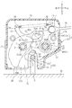
- the vehicle latch device 1 is configured by housing a mechanical component such as a latch 30 in a housing 2.
- the housing 2 is formed with an entrance groove 2A that opens to the right in FIG. 1, and the latch 30 is in a closed state or an open state when the hook-shaped portion advances or retracts into the entrance groove 2A. .
- the vehicle latch device 1 can be locked by being pressed and engaged with the rod-like portion P1 (see FIG. 5) of the striker P fixed to the vehicle main body from the unlocked state in which the latch 30 is opened. Further, as will be described in detail later, the vehicle latch device 1 can be unlocked by pulling the rod 70 to operate the latch 30 from the closed state to the open state.
- the vehicle latch device 1 mainly includes a housing 2, a latch 30, a ratchet 40, a lever member 50, a rod 70, and a load receiving member 80. .
- the top, bottom, left, right, and front and rear directions indicated by arrows in FIG. 2 are used. Needless to say, it can be used in a posture.
- the housing 2 includes a resin housing 10 made of resin and a reinforcing plate 20 made of steel plate (metal).
- the vehicle latch device 1 employs the resin casing 10 to achieve a significant weight reduction, and necessary rigidity and strength are ensured by partially providing the reinforcing plate 20.
- the resin casing 10 is integrally formed by connecting a tray-like lower case 10A having an opening on one side and an upper case 10B by a hinge 19 formed of a thin portion.
- a resin casing 10 can be formed by integral molding with a set of molds.
- the upper case 10B can be rotated around the hinge 19 with respect to the lower case 10A, and is shaped like a box by matching the openings of the upper case 10B and the lower case 10A.
- the lower case 10A is formed in a tray shape including a flat base portion 16A and a side wall portion 17A that rises at a part of the outer edge of the base portion 16A.
- An entry groove 15A corresponding to the entry groove 2A is formed on the lower edge of the base portion 16A.
- the cylindrical first shaft 11 and the second shaft 12 extend inward on the left and right sides of the entrance groove 15A and slightly apart upward from the entrance groove 15A. Both the first shaft 11 and the second shaft 12 are integrated with the base portion 16A.
- the first shaft 11 has a bolt hole 11H that is a through hole having a circular cross section along the axial direction.
- the second shaft 12 also has a bolt hole 12H that is a through hole having a circular cross section along the axial direction.
- Both the bolt hole 11 ⁇ / b> H and the bolt hole 12 ⁇ / b> H have substantially the same diameter as the shaft portion 91 of the bolt 90.
- the upper case 10B is configured substantially symmetrically with the lower case 10A with respect to the hinge 19 with respect to the inside of the resin casing 10, except that the first shaft 11 and the second shaft 12 are not provided.
- the upper case 10B is formed in a tray shape including a flat base portion 16B and a side wall portion 17B that rises at a part of the outer edge of the base portion 16B.
- An entry groove 15B corresponding to the entry groove 2A is formed on the upper edge (lower side after assembly) of the base portion 16B.
- the base portion 16B is formed on the left and right sides of the entry groove 15B slightly apart from the entry groove 15A to the lower side (the upper side after assembly), and bolt holes 13P and 13Q are formed corresponding to the bolt holes 11H and 12H, respectively. ing.
- the reinforcing plate 20 is formed so as to cover a part other than the upper part of the outer side of the lower case 10 ⁇ / b> A, and a side wall that rises inward from the left end and the right end among the outer edges of the flat base part 21 and the base part 21. Part 27.
- the side wall 27 of the reinforcing plate 20 can be temporarily assembled with the lower case 10A by engaging with the side wall 17A of the lower case 10A.
- the flange 28 bent up toward the outer side is formed on the outer edge of the reinforcing plate 20.
- the flange 28 is a part that contacts the load receiving member 80 and supports the force received by the load receiving member 80 from the rod-like portion P1 (see FIG. 5) of the striker P.
- the latch 30 is a member that engages and disengages the rod-like portion P1 of the striker P and locks or unlocks the vehicle latch device 1.
- the latch 30 is formed by punching a thick metal plate, has a first hole portion 31 penetrating in the thickness direction, and the first hole portion 31 is fitted to the outside of the first shaft 11 to be attached to the resin casing 10. It is rotatably supported.
- the latch 30 includes a metal latch main body 30A and a resin cover 30B that covers the front surface and part of the side edge of the latch main body 30A and is more flexible than the latch main body 30A.
- the cover 30 ⁇ / b> B is provided to improve the slidability with the ratchet 40.
- the cover 30B is combined with the latch body 30A along the axial direction of the first hole 31.
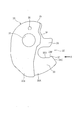
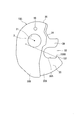
- the latch 30 has a groove 32 that receives the rod-like portion P ⁇ b> 1, and a portion that forms the outside of the groove 32 is a hook-like portion 33, The protrusion 39 protrudes from the vicinity of the first hole 31.
- the latch 30 is formed with a lock recess 34 that is recessed so as to approach the first hole 31 at the upper right edge in the posture of FIG. 5.
- An outer peripheral portion (side portion) adjacent to the left side of the lock recess 34 is an open contact surface 35 that the ratchet 40 contacts and maintains the open state of the latch 30 when the latch 30 is opened.
- the open contact surface 35 is a convex curved surface toward the outside, and the direction from the outer peripheral surface toward the center of the curvature circle in the entire range in which the lock engaging portion 42A of the ratchet 40 described later contacts (in FIG. 5). (See arrow) is shifted to one side, here right side, with respect to the axis of rotation of latch 30. For this reason, the force received by the latch 30 from the lock engaging portion 42A works to rotate the latch 30 in the clockwise direction, that is, toward the open state. Further, since the latch 30 pivotally supports the lever member 50, a pin 36 protruding to the front side is press-fitted.
- the hook-shaped portion 33 is opposed to the rod-shaped portion P1 from the lower side in the locked state in which the rod-shaped portion P1 is engaged as shown in FIG. 5, and is closer than the first support surface 38A and the first support surface 38A. It has a projecting portion 37 that is located on the distal end side of the bowl-shaped portion 33 and projects from the first support surface 38A, and a second support surface 38B that is a surface facing the rod-shaped portion P1 in the projecting portion 37.
- the first support surface 38A and the second support surface 38B face different directions, and are arranged adjacent to each other so that the rod-like portions P1 can be in contact with each other at the same time.
- the rod-shaped part P1 has a columnar shape.
- the first support surface 38A and the second support surface 38B are flat surfaces, convex curved surfaces, or concave curved surfaces having a radius of curvature larger than the radius of the rod-shaped portion in order to be able to contact the rod-shaped portion P1 simultaneously.
- both the first support surface 38A and the second support surface 38B are flat surfaces.
- the first support surface 38A and the second support surface 38B face different directions and have a sufficient length, so that the bar-shaped portion P1 is formed at the corner formed by the first support surface 38A and the second support surface 38B. When positioned at the portion, the first support surface 38A and the second support surface 38B can simultaneously abut against the rod-shaped portion P1.
- the side surface 38C on the distal end side of the hook-shaped portion 33 of the protruding portion 37 is overlapped with the edge of the entry groove 2A when viewed along the rotation axis X of the latch 30 in the unlocked state shown in FIG. Along.
- tip part and the protrusion part 37 of the latch 30 it does not inhibit that the rod-shaped part P1 enters into the entrance groove 2A. That is, the rod-like portion P1 and the latch 30 can be smoothly engaged.
- the protrusion 37 is exposed from the flexible cover 30B. Thereby, when the 2nd support surface 38B of the protrusion part 37 supports the rod-shaped part P1, it can support firmly by latch main body 30A itself. Further, in the case where the cover 30B is not a type coated on the latch body 30A but an assembled type, the protrusions 37 are exposed from the cover 30B, so that the cover 30B can be easily assembled to the latch body 30A. It is.
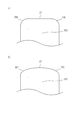
- the protruding portion 37 is provided over the entire width of the latch body 30A in the axial direction. For this reason, the protrusion part 37 is provided with sufficient rigidity, and can support the rod-shaped part P1 firmly. Then, rounded chamfers 38D are formed at both ends of the protruding portion 37 in the axial direction. For this reason, the protrusion 37 is not caught on the inner surface of the resin casing 10, and the latch 30 can move smoothly in the resin casing 10.
- the chamfered shape may be chamfered by a flat surface, or as shown in FIG. 4B, a chamfer 38E by gentle rounding may be formed, and the ridgeline of the projecting portion 37 may have a barrel shape as a whole. Good.
- the ratchet 40 is a substantially plate-like member made of metal, and the second hole portion 41 penetrating in the thickness direction is fitted to the outside of the second shaft 12 of the resin housing 10.
- the rotation axis of the ratchet 40 is parallel to the rotation axis of the latch 30.
- the ratchet 40 has a substantially fan-shaped main body portion 42 at the upper left of the second hole portion 41, and a lock engaging portion 42 ⁇ / b> A with which the lower left corner of the main body portion 42 contacts the latch 30.
- the lock engaging portion 42A enters the lock recess 34 of the latch 30 in the closed state of the latch 30 to maintain the closed state of the latch 30, and in contact with the open contact surface 35 in the open state of the latch 30. Functions to maintain state.
- an arm 43 that extends further upward is formed.
- a hook 44 is formed on which a right end of a tension spring 75 as an example of an urging member is hooked.
- a tension spring 75 as an example of an urging member is hooked.
- another part such as a rivet is fixed to the arm 43 so that the end of the tension spring 75 is engaged.
- the number of parts can be reduced compared to the structure to be stopped.
- a hole 48 is formed in the arm 43 as shown in FIG. 2, and a rod 70 for operating the vehicle latch device 1 from the locked state to the unlocked state is coupled to the hole 48 so as to be swingable by a rivet 71. Has been.
- a pin 45 projecting forward is press-fitted to the right side of the lock engaging portion 42 ⁇ / b> A in the main body portion 42.
- the ratchet 40 has a flange 47 that protrudes forward in the axial direction of the hole around the second hole portion 41.
- the flange 47 protrudes in a size corresponding to the thickness of the lever member 50, and when the latch 30 is closed, the lever member 50 abuts against the flange 47 by the urging force of the tension spring 75, thereby preventing play of the lever member 50. It has come to be.
- the lever member 50 is an operation mechanism for interlocking the operation of the ratchet 40 with the latch 30.
- the lever member 50 is a long and thin plate-like member, and is supported by the latch 30 so that the hole 51 formed at substantially the center in the longitudinal direction fits the pin 36 of the latch 30.
- the lever member 50 has an operating arm 52 extending from the rotating shaft toward the lower right and an operating arm 53 extending upward.
- the operating arm 52 is formed with a deformed rectangular guide hole 52A.
- the pin 45 of the ratchet 40 enters the guide hole 52A.
- the distal end of the operating arm 52 serves as a stopper surface 52 ⁇ / b> B that contacts the flange 47 of the ratchet 40 and prevents play of the lever member 50.
- a hook 54 is formed at the tip of the operation arm 53, and the left end of the tension spring 75 is hooked on the hook 54.
- the end of the tension spring 75 is secured to the operation arm 53 by locking the end of the tension spring 75 with a hook 54 having a hook-like shape at the tip of the operation arm 53.
- the number of parts can be reduced as compared with the structure that locks.
- each end of the tension spring 75 is hooked on the ratchet 40 and the lever member 50, and an urging force is applied so as to always attract the main body 42 of the ratchet 40 and the operation arm 53 of the lever member 50.
- This urging force also acts to give a force for urging the lock engaging portion 42 ⁇ / b> A of the ratchet 40 toward the latch 30.
- the load receiving member 80 is a resin-made member that comes into contact with the rod-like portion P1 of the striker P and receives a load from the striker P. Although details are omitted, the load receiving surface 89A at the lower end of the load receiving member 80 abuts on the rod-shaped portion P1 in the locked state, and the load entering the load receiving member 80 from the rod-shaped portion P1 is caused by the flange 28 ( 2) and is received by the reinforcing plate 20.
- the lower case 10 ⁇ / b> A and the upper case 10 ⁇ / b> B are fastened together by a bolt 90 to have a box shape, and are fixed to the bracket S ⁇ b> 2 together with the reinforcing plate 20.
- the bolt 90 includes a shaft portion 91, a screw portion 92 provided at the distal end of the shaft portion 91, and a flanged head 93 provided at the proximal end.
- the shaft portion 91 has a diameter larger than that of the crest portion of the screw portion 92, and receives a fastening force when the shaft portion 91 is fastened to the welding nut WN at the stepped portion. Thereby, cost reduction can be aimed at compared with the case where a metal color is used.
- the lower case 10A and the upper case 10B are assembled in a box shape with the respective members such as the latch 30 assembled therein and facing each opening side, and the shaft portion 91 of the bolt 90 is inserted into the bolt hole 11H.
- the screw portion 92 is fixed to the bracket S2 by screwing the screw portion 92 with the welding nut WN of the bracket S2.
- a spring washer 95 is interposed between the flanged head 93 and the reinforcing plate 20, and the vehicle latch device 1 is sandwiched between the bracket S 2 and the flanged head 93 by the elastic force of the spring washer 95.
- the fastening state in the first shaft 11 by the bolt 90 has been described with reference to FIG. 6, but the fastening in the second shaft 12 by the bolt 90 is exactly the same. Therefore, the description of the fastening in the second shaft 12 is omitted.
- the operation of the vehicle latch device 1 configured as described above will be described.
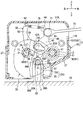
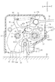
- the rod-like portion P1 of the striker P is in the deepest part of the entry groove 2A of the housing 2, and the hook-like portion 33 of the latch 30 holds the rod-like portion P1 from below.
- a lock engaging portion 42A enters the lock recess 34 of the latch 30 to restrict the rotation of the latch 30. That is, the latch 30 is in a closed state, and the vehicle latch device 1 is in a locked state.
- the tension spring 75 generates a tensile force
- the lock engaging portion 42 ⁇ / b> A of the ratchet 40 is in contact with the bottom of the lock recess 34.
- the rod-like portion P1 of the striker P is in contact with the load receiving surface 89A of the load receiving member 80, and the load applied to the vehicle latch device 1 from the striker P via the load receiving member 80 is the flange 28 of the reinforcing plate 20. (Refer to FIG. 2), the reinforcing plate 20 is received.
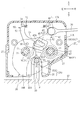
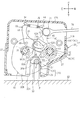
- the vehicle latch device 1 When the rod 70 is pulled from the state before the operation shown in FIG. 5, the vehicle latch device 1 first rotates the ratchet 40 clockwise as shown in FIG. 7, and the pin 45 of the ratchet 40 moves the guide hole 52A. The lever member 50 is rotated counterclockwise while the tension spring 75 is extended. In FIG. 7, there is almost no change from FIG. 5, but the force applied to the lever member 50 tries to rotate the latch 30 little by little clockwise through the pin 36.
- the ratchet 40 pushes the latch 30 by the urging force of the tension spring 75.
- the force acts as a force (rotational moment) that rotates the latch 30 clockwise, that is, toward the open state.
- the latch 30 rotates clockwise while the opening contact surface 35 slides on the lock engaging portion 42A due to this rotational moment, the latch 30 is opened as shown in FIG. 10, and the rod-like portion P1 of the striker P is opened. Can be detached from the entry groove 2A. That is, the vehicle latch device 1 is unlocked.
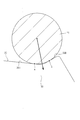
- the rod-shaped portion P1 contacts the first support surface 38A at the contact point A and contacts the second support surface 38B at the contact point B. That is, the rod-shaped portion P1 is pressed against the bowl-shaped portion 33 as shown by the arrow in FIG. 12, and this pressing force is caused by the rod-shaped portion P1 simultaneously contacting the first support surface 38A and the second support surface 38B. Supported by these two surfaces. Therefore, according to the vehicle latch device 1 of the present embodiment, the latch 30 can firmly hold the rod-like portion P1 even when a force is applied to remove the vehicle latch device 1 from the striker P.
- the present invention is not limited to the above-described embodiment and can be appropriately modified and implemented.
- the protruding portion 37 protrudes greatly from the first support surface 38A as long as the rod-shaped portion P1 can be smoothly detached from the groove 32.
- the second support surface 138 ⁇ / b> B faces the rotation axis X with respect to the housing 2 of the latch 130, or the proximal end side of the hook-shaped portion 33 with respect to the rotation axis X. Is directed toward the second support surface 138B from the rod-shaped portion P1, the hook-shaped portion 33 can hold the rod-shaped portion P1 firmly.
- the cover 30B of the latch 30 is combined with the latch main body 30A along the axial direction of the first hole portion 31, but FIG. Like the latch 250 shown to b), it can also be set as the form assembled
- the cover 230 according to this modification is formed by injection molding of resin, and has a surface on one side (here, the rear side) that extends so as to be orthogonal to the rotation axis X of the latch body 30A.
- the second cover portion 232 is connected, and connecting portions 235A and 235B that cover the side portions of the latch main body 30A are provided.
- the cover 230 is less likely to be detached from the latch body 30A because there are two or more connecting portions.
- the second cover portion 232 includes a heel cover portion 232A that covers the distal end portion of the ridge portion 33, and a protrusion cover portion 232B that covers the lower half of the protrusion portion 39.
- the connecting portion 235A extends so as to cover a portion along the inner surface of the groove 32 and a tip of the protruding portion 39 in the side portion of the latch main body 30A.
- the connecting portion 235B extends so as to cover the lower side of the hook-shaped portion 33 among the side portions of the latch main body 30A.
- the first cover portion 231 and the second cover portion 232 are arranged so as not to overlap with each other along the rotation axis X of the latch main body 30A. Thereby, the cover 230 can be easily punched by punching along the rotation axis X during injection molding.
- a through hole 237 is formed in the first cover portion 231 at a position corresponding to the first hole portion 31 where the first shaft 11 that is a support shaft of the latch body 30A is disposed.
- the first cover portion 231 has a through hole 238 corresponding to the pin 36 of the latch body 30A. Furthermore, the edge part which opposes the groove
- the cover 230 configured as described above is assembled to the latch body 30A along a plane orthogonal to the rotation axis X. Specifically, the cover 230 is assembled along the longitudinal direction of the groove 32 with respect to the latch body 30A. At the time of this assembly, the first cover portion 231 is slightly bent rearward while the hook-shaped portion 33 is fitted into the annular portion 241 so that the protrusion 39 is sandwiched between the first cover portion 231 and the protrusion cover portion 232B. . At this time, the through hole 238 is passed through the pin 36, and the engaging portion 239 is moved over the rear side surface of the latch body 30A and engaged with the left side portion of the latch body 30A.
- the cover 230 is not easily detached from the latch body 30A.
- the cover 230 does not shift in the direction of the rotation axis X with respect to the latch main body 30A due to the fitting of the hook-shaped portion 33 and the annular portion 241 and the engagement of the protrusion 39 and the protrusion cover 232B.
- the latch 250 assembled in this way is supported by the first shaft 11 with the first shaft 11 inserted through the first hole 31 and the through hole 237.
- the cover 230 is pivotally supported in this way, the cover 230 cannot be displaced in the direction orthogonal to the rotation axis X, and thus it is prevented from being displaced or detached from the latch body 30A.
- the cover 230 of this modified example since the protruding portion 37 is exposed from the cover 230, the operating sound of the latch 30 can be reduced by the flexible cover 230, and the protruding portion 37 is exposed from the cover 230. Therefore, the rod-like portion P1 can be firmly supported by the latch body 30A itself. Further, when the cover 230 is assembled to the latch main body 30A, the assembling work is easy.
- the cover 30B of the latch 30 may be provided in a form in which the latch body 30A is coated with rubber.
- the vehicle latch device 1 may be provided not only when used for a backrest of a vehicle seat such as a vehicle but also for a seating portion or a leg of the vehicle seat. It can also be used as a locking device.
- the vehicle seat may also be a ship or airplane seat other than a vehicle.
Abstract
Description
また、本発明は、ラッチを堅牢に構成しつつ、棒状部とラッチの係合をスムーズにすることを目的とする。
さらに、本発明は、筐体にラッチが引っ掛かることを抑制して、ラッチをスムーズに作動させることを目的とする。 Then, an object of this invention is to provide the latch apparatus for vehicles which improved the retention strength of rod-shaped parts, such as a striker.
Another object of the present invention is to make the engagement between the rod-shaped portion and the latch smooth while the latch is firmly constructed.
Furthermore, it is an object of the present invention to suppress the latch from being caught on the housing and operate the latch smoothly.
上ケース10Bは、第1軸11および第2軸12が無い以外は、樹脂筐体10の内部については、ヒンジ19を基準として下ケース10Aと略対称に構成されている。上ケース10Bは、平板状のベース部16Bと、ベース部16Bの外縁の一部において立ち上がる側壁部17Bとを備えてトレイ状に形成されている。ベース部16Bの上側(組立後の下側)の縁には進入溝2Aに対応する進入溝15Bが形成されている。また、ベース部16Bは、進入溝15Bの左右両側に、進入溝15Aから下側(組立後の上側)に少し離れてボルト孔13P,13Qが、それぞれボルト孔11H,12Hに対応して形成されている。 The
The
また、ラッチ30は、レバー部材50を軸支するため、前側に突出するピン36が圧入されている。 As shown in FIG. 3, the
Further, since the
図5の作動前の状態において、ストライカPの棒状部P1は、筐体2の進入溝2Aの最も奥に入り込んでおり、ラッチ30の鉤状部33が棒状部P1を下から抱え込んでいる。そして、ラッチ30のロック凹部34にはロック係止部42Aが入り込んでラッチ30の回動を規制している。すなわち、ラッチ30は閉状態であり、乗物用ラッチ装置1はロック状態にある。このとき、引張バネ75は引張力を発生しており、ラチェット40のロック係止部42Aがロック凹部34の底に当接している。また、ストライカPの棒状部P1は、荷重受け部材80の荷重受け面89Aに当接しており、ストライカPから乗物用ラッチ装置1に掛かる荷重は荷重受け部材80を介して補強板20のフランジ28(図2参照)に伝わり、補強板20が受けている。 The operation of the
In the state before the operation of FIG. 5, the rod-like portion P1 of the striker P is in the deepest part of the
例えば、突出部37は、棒状部P1がスムーズに溝32から着脱できる限り第1支持面38Aから大きく突出しているのが望ましい。このとき、図13に示すラッチ130のように、第2支持面138Bは、ラッチ130の筐体2に対する回動軸Xを向くか、当該回動軸Xよりも鉤状部33の基端側を向いていると、棒状部P1から第2支持面138Bに非常に大きな力が掛かっても、鉤状部33が棒状部P1をしっかりと保持することができる。なお、逆に、第2支持面138Bがラッチ130の筐体2に対する回動軸Xよりも、溝32の開口側(図13の右側)に向いていると、鉤状部33と棒状部P1が係合しやすくなる。 Although one embodiment of the present invention has been described above, the present invention is not limited to the above-described embodiment and can be appropriately modified and implemented.
For example, it is desirable that the protruding
Claims (7)
- 棒状部に係合または離脱することでロックまたはロック解除する乗物用ラッチ装置であって、
筐体と、
前記筐体に回動可能に支持され、前記棒状部に係合してロック状態を形成する鉤状部を有するラッチとを備え、
前記鉤状部は、
前記ロック状態において前記棒状部に対向する第1支持面と、
前記第1支持面よりも鉤状部の先端側に位置し前記第1支持面から突出する突出部と、
当該突出部における前記棒状部に対向する面である第2支持面とを有し、
前記第1支持面と前記第2支持面は異なる向きを向いていることで、前記棒状部に対し同時に当接可能に配置されていることを特徴とする乗物用ラッチ装置。 A vehicle latch device that locks or unlocks by engaging or disengaging from a rod-shaped portion,
A housing,
A latch having a hook-shaped portion that is rotatably supported by the housing and engages with the rod-shaped portion to form a locked state;
The hook-shaped portion is
A first support surface facing the rod-like portion in the locked state;
A protruding portion that is located on the distal end side of the bowl-shaped portion with respect to the first supporting surface and protrudes from the first supporting surface;
A second support surface that is a surface facing the rod-shaped portion in the protrusion,
The vehicle latch device according to claim 1, wherein the first support surface and the second support surface are arranged in different directions so that the first support surface and the second support surface can simultaneously contact the rod-shaped portion. - 前記棒状部は円柱形状を有し、
前記第1支持面は、平面、凸曲面または前記棒状部の半径よりも大きな曲率半径の凹曲面であり、
前記第2支持面は、平面、凸曲面または前記棒状部の半径よりも大きな曲率半径の凹曲面であることを特徴とする請求項1に記載の乗物用ラッチ装置。 The rod-shaped part has a cylindrical shape,
The first support surface is a flat surface, a convex curved surface, or a concave curved surface having a radius of curvature larger than the radius of the rod-shaped portion,
2. The vehicle latch device according to claim 1, wherein the second support surface is a flat surface, a convex curved surface, or a concave curved surface having a radius of curvature larger than a radius of the rod-shaped portion. - 前記第2支持面は、前記ラッチの前記筐体に対する回動軸を向くか、当該回動軸よりも、前記鉤状部の基端側を向いていることを特徴とする請求項1または請求項2に記載の乗物用ラッチ装置。 The said 2nd support surface has faced the rotating shaft with respect to the said housing | casing of the said latch, or has faced the base end side of the said hook-shaped part rather than the said rotating shaft. Item 3. The vehicle latch device according to Item 2.
- 前記筐体は、前記棒状部が進入する進入溝が形成されており、
前記突出部の前記鉤状部の先端側の側面は、前記ラッチがロック解除状態にあるときに、前記ラッチの回動軸に沿って見て、前記進入溝の縁に沿っていることを特徴とする請求項1から請求項3のいずれか1項に記載の乗物用ラッチ装置。 The housing is formed with an entry groove into which the rod-like portion enters,
The side surface of the protruding portion on the distal end side of the hook-shaped portion is along the edge of the entry groove when viewed along the rotation axis of the latch when the latch is in the unlocked state. The vehicle latch device according to any one of claims 1 to 3. - 前記ラッチは、ラッチ本体と、ラッチ本体の一部を覆い、前記ラッチ本体より柔軟なカバーを含んで構成され、
前記突出部は、前記カバーから露出していることを特徴とする請求項1から請求項4のいずれか1項に記載の乗物用ラッチ装置。 The latch includes a latch body and a cover that covers a part of the latch body and is more flexible than the latch body.
The vehicle latch device according to any one of claims 1 to 4, wherein the protrusion is exposed from the cover. - 前記突出部は、前記ラッチの軸方向における全幅にわたって設けられていることを特徴とする請求項1から請求項5のいずれか1項に記載の乗物用ラッチ装置。 The vehicle latch device according to any one of claims 1 to 5, wherein the protrusion is provided over the entire width in the axial direction of the latch.
- 前記突出部は、前記ラッチの軸方向における両端部に面取りが形成されていることを特徴とする請求項1から請求項6のいずれか1項に記載の乗物用ラッチ装置。 The vehicle latch device according to any one of claims 1 to 6, wherein the protruding portion is formed with chamfers at both end portions in the axial direction of the latch.
Priority Applications (4)
| Application Number | Priority Date | Filing Date | Title |
|---|---|---|---|
| CN201380049174.0A CN104661867B (en) | 2012-09-21 | 2013-09-10 | Vehicle latch device |
| EP13838924.2A EP2899064B1 (en) | 2012-09-21 | 2013-09-10 | Vehicle latch device |
| US14/428,704 US10060166B2 (en) | 2012-09-21 | 2013-09-10 | Vehicle latch device |
| BR112015005924-4A BR112015005924B1 (en) | 2012-09-21 | 2013-09-10 | VEHICLE LOCK DEVICE |
Applications Claiming Priority (2)
| Application Number | Priority Date | Filing Date | Title |
|---|---|---|---|
| JP2012207852A JP5944804B2 (en) | 2012-09-21 | 2012-09-21 | Vehicle latch device |
| JP2012-207852 | 2012-09-21 |
Publications (1)
| Publication Number | Publication Date |
|---|---|
| WO2014045933A1 true WO2014045933A1 (en) | 2014-03-27 |
Family
ID=50341247
Family Applications (1)
| Application Number | Title | Priority Date | Filing Date |
|---|---|---|---|
| PCT/JP2013/074321 WO2014045933A1 (en) | 2012-09-21 | 2013-09-10 | Vehicle latch device |
Country Status (6)
| Country | Link |
|---|---|
| US (1) | US10060166B2 (en) |
| EP (1) | EP2899064B1 (en) |
| JP (1) | JP5944804B2 (en) |
| CN (1) | CN104661867B (en) |
| BR (1) | BR112015005924B1 (en) |
| WO (1) | WO2014045933A1 (en) |
Cited By (1)
| Publication number | Priority date | Publication date | Assignee | Title |
|---|---|---|---|---|
| DE102015004283A1 (en) * | 2015-04-08 | 2016-10-13 | Kiekert Aktiengesellschaft | Motor vehicle door lock |
Families Citing this family (11)
| Publication number | Priority date | Publication date | Assignee | Title |
|---|---|---|---|---|
| WO2012173084A1 (en) * | 2011-06-17 | 2012-12-20 | テイ・エス テック株式会社 | Latching device for vehicles |
| US9969308B2 (en) * | 2012-12-12 | 2018-05-15 | Shiroki Corporation | Lock device |
| EP3045387A1 (en) * | 2015-01-14 | 2016-07-20 | AIRBUS HELICOPTERS DEUTSCHLAND GmbH | An actuating system for an actuatable door and an actuatable door having such an actuating system |
| US10221621B2 (en) * | 2016-01-15 | 2019-03-05 | Crestron Electronics, Inc. | Roller shade latching apparatus |
| JP6836053B2 (en) * | 2016-09-30 | 2021-02-24 | テイ・エス テック株式会社 | Vehicle latch device |
| KR102417390B1 (en) * | 2017-10-13 | 2022-07-06 | 현대자동차주식회사 | Latch cover assembly capable of opening and closing according to folding of rear seat of vehicle |
| US11047150B2 (en) | 2018-01-23 | 2021-06-29 | Schlage Lock Company Llc | Noise-reducing strike box |
| CN111188542B (en) * | 2018-11-15 | 2022-11-15 | 开开特股份公司 | Automobile lock |
| USD902006S1 (en) * | 2019-01-03 | 2020-11-17 | Zhejiang Oklead Auto Parts Co., Ltd. | Vehicle door lock |
| CZ308266B6 (en) * | 2019-01-22 | 2020-04-01 | Brano A.S. | Lock latch operating mechanism |
| US11603023B2 (en) | 2020-02-14 | 2023-03-14 | Waymo Llc | Lockout assembly for folding vehicle seats |
Citations (6)
| Publication number | Priority date | Publication date | Assignee | Title |
|---|---|---|---|---|
| JP2002201843A (en) * | 2000-12-29 | 2002-07-19 | T S Tec Kk | Inertia lock device and collapsible seat |
| JP4318213B2 (en) | 2004-03-19 | 2009-08-19 | テイ・エス テック株式会社 | Vehicle seat locking device |
| JP2011105132A (en) * | 2009-11-17 | 2011-06-02 | Mitsui Kinzoku Act Corp | Latch device |
| JP2011168961A (en) * | 2010-02-16 | 2011-09-01 | Toyota Boshoku Corp | Lock device |
| JP2012505786A (en) * | 2008-10-17 | 2012-03-08 | ジョンソン・コントロールズ・ゲー・エム・ベー・ハー | Fixed elements for vehicle seats |
| JP2013226993A (en) * | 2012-04-27 | 2013-11-07 | Fuji Kiko Co Ltd | Fixing device of seat |
Family Cites Families (28)
| Publication number | Priority date | Publication date | Assignee | Title |
|---|---|---|---|---|
| US3614146A (en) * | 1969-08-15 | 1971-10-19 | Atwood Vacuum Machine Co | Vehicle door latch |
| US3695662A (en) * | 1970-09-18 | 1972-10-03 | Atwood Vacuum Machine Co | Latch for vehicle doors |
| DE2552209C3 (en) * | 1975-11-21 | 1980-09-25 | Volkswagenwerk Ag, 3180 Wolfsburg | Detachable connection between an operating rod or an operating cable and a door lock |
| DE2725345C2 (en) * | 1977-06-04 | 1985-05-23 | Daimler-Benz Ag, 7000 Stuttgart | Locking bolt bent from a sheet steel blank for a motor vehicle door lock |
| DE3507405C1 (en) * | 1985-03-02 | 1986-05-15 | Daimler-Benz Ag, 7000 Stuttgart | Locking device for a motor vehicle door |
| DE3839568C3 (en) * | 1988-11-24 | 1999-03-18 | Ewald Witte Gmbh & Co Kg | Lock for doors or flaps |
| JP2544471Y2 (en) * | 1991-02-26 | 1997-08-20 | 株式会社タチエス | Tumble sheet structure |
| GB2282843B (en) * | 1993-10-13 | 1996-03-20 | Rockwell Body & Chassis Syst | Latch assembly |
| US5474339A (en) * | 1993-10-15 | 1995-12-12 | Kelsey-Hayes Company | Door latch with double locking antitheft feature |
| FR2714415B1 (en) * | 1993-12-28 | 1996-03-08 | Coutier Moulage Gen Ind | Door lock or the like and, in particular, of a motor vehicle. |
| JP3212487B2 (en) * | 1995-06-13 | 2001-09-25 | 三井金属鉱業株式会社 | Insert molding die |
| JP3609217B2 (en) * | 1996-09-30 | 2005-01-12 | 株式会社大井製作所 | Locking device |
| JP3430436B2 (en) * | 1997-03-28 | 2003-07-28 | 株式会社大井製作所 | Door lock device for automobile |
| US5918918A (en) * | 1997-05-27 | 1999-07-06 | General Motors Corporation | Anti-noise collar for vehicle latch |
| DE10164829B4 (en) * | 2001-01-02 | 2006-07-13 | Brose Schließsysteme GmbH & Co.KG | Motor vehicle door lock, designed as an electric lock |
| ITTO20020512A1 (en) * | 2002-06-14 | 2003-12-15 | Intier Automotive Closures Spa | LOCK FOR A VEHICLE DOOR |
| DE602004011755T2 (en) * | 2003-02-21 | 2009-01-29 | Magna Closures Inc., Newmarket | LOCK ARRANGEMENT FOR BONNET |
| DE102004002358B3 (en) * | 2004-01-15 | 2005-05-19 | Keiper Gmbh & Co. Kg | Releasable locking device for automobile passenger seat has bearing element for pivoted catch and/or security element fitted in insert of harder material than housing of locking device |
| DE102004052746B3 (en) | 2004-09-22 | 2006-04-27 | Faurecia Autositze Gmbh & Co.Kg | Hinged backrest`s unlocking condition signaling device for passenger car seat, has stopper to displace axially when backrest is unlocked so that actuating knob in its signaling position projects farther from housing than in locked position |
| DE102004045988B3 (en) | 2004-09-22 | 2005-12-01 | Faurecia Autositze Gmbh & Co. Kg | Display for signaling the non-locking of a folding backrest of a motor vehicle seat |
| JP4688685B2 (en) * | 2006-01-23 | 2011-05-25 | 三井金属アクト株式会社 | Vehicle seat lock device |
| JP4608443B2 (en) * | 2006-01-23 | 2011-01-12 | 三井金属鉱業株式会社 | Locking device with plate material fixing structure |
| WO2009069851A1 (en) * | 2007-11-27 | 2009-06-04 | Austem Co., Ltd. | Latch assembly for vehicle seat |
| DE102008033304B4 (en) * | 2008-07-11 | 2018-01-04 | Adient Luxembourg Holding S.à.r.l. | Locking device for a vehicle seat and vehicle seat |
| WO2011094736A1 (en) * | 2010-02-01 | 2011-08-04 | Strattec Security Corporation | Latch mechanism and latching method |
| JP5140893B2 (en) | 2010-06-09 | 2013-02-13 | 三井金属アクト株式会社 | Latch device |
| KR101154803B1 (en) * | 2010-09-30 | 2012-06-18 | 현대자동차주식회사 | Seat latch structure |
| JP5637881B2 (en) * | 2011-01-31 | 2014-12-10 | 富士機工株式会社 | Sheet fixing device |
-
2012
- 2012-09-21 JP JP2012207852A patent/JP5944804B2/en active Active
-
2013
- 2013-09-10 BR BR112015005924-4A patent/BR112015005924B1/en active IP Right Grant
- 2013-09-10 CN CN201380049174.0A patent/CN104661867B/en active Active
- 2013-09-10 WO PCT/JP2013/074321 patent/WO2014045933A1/en active Application Filing
- 2013-09-10 EP EP13838924.2A patent/EP2899064B1/en active Active
- 2013-09-10 US US14/428,704 patent/US10060166B2/en active Active
Patent Citations (6)
| Publication number | Priority date | Publication date | Assignee | Title |
|---|---|---|---|---|
| JP2002201843A (en) * | 2000-12-29 | 2002-07-19 | T S Tec Kk | Inertia lock device and collapsible seat |
| JP4318213B2 (en) | 2004-03-19 | 2009-08-19 | テイ・エス テック株式会社 | Vehicle seat locking device |
| JP2012505786A (en) * | 2008-10-17 | 2012-03-08 | ジョンソン・コントロールズ・ゲー・エム・ベー・ハー | Fixed elements for vehicle seats |
| JP2011105132A (en) * | 2009-11-17 | 2011-06-02 | Mitsui Kinzoku Act Corp | Latch device |
| JP2011168961A (en) * | 2010-02-16 | 2011-09-01 | Toyota Boshoku Corp | Lock device |
| JP2013226993A (en) * | 2012-04-27 | 2013-11-07 | Fuji Kiko Co Ltd | Fixing device of seat |
Cited By (1)
| Publication number | Priority date | Publication date | Assignee | Title |
|---|---|---|---|---|
| DE102015004283A1 (en) * | 2015-04-08 | 2016-10-13 | Kiekert Aktiengesellschaft | Motor vehicle door lock |
Also Published As
| Publication number | Publication date |
|---|---|
| JP2014061781A (en) | 2014-04-10 |
| BR112015005924B1 (en) | 2021-07-27 |
| US10060166B2 (en) | 2018-08-28 |
| EP2899064A1 (en) | 2015-07-29 |
| US20150218856A1 (en) | 2015-08-06 |
| JP5944804B2 (en) | 2016-07-05 |
| CN104661867A (en) | 2015-05-27 |
| BR112015005924A2 (en) | 2017-07-04 |
| EP2899064A4 (en) | 2016-04-20 |
| EP2899064B1 (en) | 2018-11-28 |
| CN104661867B (en) | 2017-04-12 |
Similar Documents
| Publication | Publication Date | Title |
|---|---|---|
| WO2014045933A1 (en) | Vehicle latch device | |
| JP6005782B2 (en) | Vehicle latch device | |
| JP4851869B2 (en) | Vehicle door latch device | |
| US8662545B2 (en) | Vehicle door latch apparatus | |
| JP4866668B2 (en) | Vehicle door latch device | |
| JP5729970B2 (en) | Vehicle locking device | |
| JP5844075B2 (en) | Vehicle latch device | |
| JP5830789B2 (en) | Locking device | |
| JP7380693B2 (en) | car lock | |
| WO2018008598A1 (en) | Lock device production method | |
| US11299917B2 (en) | Vehicle door latch device | |
| JP6095321B2 (en) | Vehicle latch device | |
| JP2013011061A (en) | Lock device | |
| JP5730712B2 (en) | Console box device | |
| JP4820222B2 (en) | Vehicle door latch device | |
| JP2001328480A (en) | Assist grip mounting structure | |
| JP4200079B2 (en) | Connector | |
| JPH0562749U (en) | Spring mounting structure | |
| JP5199024B2 (en) | Steering lock device | |
| JP2022141012A (en) | Latching device for vehicle and manufacturing method thereof, and vehicle seat | |
| JP2009133136A (en) | Door handle device | |
| JPH08333937A (en) | Support structure of plural rotary levers | |
| JP3974334B2 (en) | Automotive locking device | |
| JP2020051214A (en) | Vehicle door lock device | |
| JP2020084546A (en) | Cable assembly structure for hood lock device |
Legal Events
| Date | Code | Title | Description |
|---|---|---|---|
| 121 | Ep: the epo has been informed by wipo that ep was designated in this application |
Ref document number: 13838924 Country of ref document: EP Kind code of ref document: A1 |
|
| WWE | Wipo information: entry into national phase |
Ref document number: 14428704 Country of ref document: US |
|
| WWE | Wipo information: entry into national phase |
Ref document number: 2013838924 Country of ref document: EP |
|
| NENP | Non-entry into the national phase |
Ref country code: DE |
|
| REG | Reference to national code |
Ref country code: BR Ref legal event code: B01A Ref document number: 112015005924 Country of ref document: BR |
|
| ENP | Entry into the national phase |
Ref document number: 112015005924 Country of ref document: BR Kind code of ref document: A2 Effective date: 20150317 |