WO2014045706A1 - 充電状態推定装置及び充電状態推定方法 - Google Patents
充電状態推定装置及び充電状態推定方法 Download PDFInfo
- Publication number
- WO2014045706A1 WO2014045706A1 PCT/JP2013/069839 JP2013069839W WO2014045706A1 WO 2014045706 A1 WO2014045706 A1 WO 2014045706A1 JP 2013069839 W JP2013069839 W JP 2013069839W WO 2014045706 A1 WO2014045706 A1 WO 2014045706A1
- Authority
- WO
- WIPO (PCT)
- Prior art keywords
- soc
- ocv
- characteristic
- value
- movement
- Prior art date
- Legal status (The legal status is an assumption and is not a legal conclusion. Google has not performed a legal analysis and makes no representation as to the accuracy of the status listed.)
- Ceased
Links
Images



Classifications
-
- B—PERFORMING OPERATIONS; TRANSPORTING
- B60—VEHICLES IN GENERAL
- B60L—PROPULSION OF ELECTRICALLY-PROPELLED VEHICLES; SUPPLYING ELECTRIC POWER FOR AUXILIARY EQUIPMENT OF ELECTRICALLY-PROPELLED VEHICLES; ELECTRODYNAMIC BRAKE SYSTEMS FOR VEHICLES IN GENERAL; MAGNETIC SUSPENSION OR LEVITATION FOR VEHICLES; MONITORING OPERATING VARIABLES OF ELECTRICALLY-PROPELLED VEHICLES; ELECTRIC SAFETY DEVICES FOR ELECTRICALLY-PROPELLED VEHICLES
- B60L58/00—Methods or circuit arrangements for monitoring or controlling batteries or fuel cells, specially adapted for electric vehicles
- B60L58/10—Methods or circuit arrangements for monitoring or controlling batteries or fuel cells, specially adapted for electric vehicles for monitoring or controlling batteries
- B60L58/12—Methods or circuit arrangements for monitoring or controlling batteries or fuel cells, specially adapted for electric vehicles for monitoring or controlling batteries responding to state of charge [SoC]
-
- G—PHYSICS
- G01—MEASURING; TESTING
- G01R—MEASURING ELECTRIC VARIABLES; MEASURING MAGNETIC VARIABLES
- G01R31/00—Arrangements for testing electric properties; Arrangements for locating electric faults; Arrangements for electrical testing characterised by what is being tested not provided for elsewhere
- G01R31/36—Arrangements for testing, measuring or monitoring the electrical condition of accumulators or electric batteries, e.g. capacity or state of charge [SoC]
- G01R31/382—Arrangements for monitoring battery or accumulator variables, e.g. SoC
- G01R31/3842—Arrangements for monitoring battery or accumulator variables, e.g. SoC combining voltage and current measurements
-
- H—ELECTRICITY
- H01—ELECTRIC ELEMENTS
- H01M—PROCESSES OR MEANS, e.g. BATTERIES, FOR THE DIRECT CONVERSION OF CHEMICAL ENERGY INTO ELECTRICAL ENERGY
- H01M10/00—Secondary cells; Manufacture thereof
- H01M10/05—Accumulators with non-aqueous electrolyte
- H01M10/052—Li-accumulators
- H01M10/0525—Rocking-chair batteries, i.e. batteries with lithium insertion or intercalation in both electrodes; Lithium-ion batteries
-
- H—ELECTRICITY
- H01—ELECTRIC ELEMENTS
- H01M—PROCESSES OR MEANS, e.g. BATTERIES, FOR THE DIRECT CONVERSION OF CHEMICAL ENERGY INTO ELECTRICAL ENERGY
- H01M10/00—Secondary cells; Manufacture thereof
- H01M10/42—Methods or arrangements for servicing or maintenance of secondary cells or secondary half-cells
- H01M10/44—Methods for charging or discharging
-
- H—ELECTRICITY
- H01—ELECTRIC ELEMENTS
- H01M—PROCESSES OR MEANS, e.g. BATTERIES, FOR THE DIRECT CONVERSION OF CHEMICAL ENERGY INTO ELECTRICAL ENERGY
- H01M10/00—Secondary cells; Manufacture thereof
- H01M10/42—Methods or arrangements for servicing or maintenance of secondary cells or secondary half-cells
- H01M10/48—Accumulators combined with arrangements for measuring, testing or indicating the condition of cells, e.g. the level or density of the electrolyte
-
- H—ELECTRICITY
- H02—GENERATION; CONVERSION OR DISTRIBUTION OF ELECTRIC POWER
- H02J—ELECTRIC POWER NETWORKS; CIRCUIT ARRANGEMENTS OR SYSTEMS FOR SUPPLYING OR DISTRIBUTING ELECTRIC POWER; SYSTEMS FOR STORING ELECTRIC ENERGY
- H02J7/00—Circuit arrangements for charging or discharging batteries or for supplying loads from batteries
- H02J7/80—Circuit arrangements for charging or discharging batteries or for supplying loads from batteries including monitoring or indicating arrangements
- H02J7/82—Control of state of charge [SOC]
-
- B—PERFORMING OPERATIONS; TRANSPORTING
- B60—VEHICLES IN GENERAL
- B60L—PROPULSION OF ELECTRICALLY-PROPELLED VEHICLES; SUPPLYING ELECTRIC POWER FOR AUXILIARY EQUIPMENT OF ELECTRICALLY-PROPELLED VEHICLES; ELECTRODYNAMIC BRAKE SYSTEMS FOR VEHICLES IN GENERAL; MAGNETIC SUSPENSION OR LEVITATION FOR VEHICLES; MONITORING OPERATING VARIABLES OF ELECTRICALLY-PROPELLED VEHICLES; ELECTRIC SAFETY DEVICES FOR ELECTRICALLY-PROPELLED VEHICLES
- B60L2240/00—Control parameters of input or output; Target parameters
- B60L2240/40—Drive Train control parameters
- B60L2240/54—Drive Train control parameters related to batteries
- B60L2240/545—Temperature
-
- B—PERFORMING OPERATIONS; TRANSPORTING
- B60—VEHICLES IN GENERAL
- B60L—PROPULSION OF ELECTRICALLY-PROPELLED VEHICLES; SUPPLYING ELECTRIC POWER FOR AUXILIARY EQUIPMENT OF ELECTRICALLY-PROPELLED VEHICLES; ELECTRODYNAMIC BRAKE SYSTEMS FOR VEHICLES IN GENERAL; MAGNETIC SUSPENSION OR LEVITATION FOR VEHICLES; MONITORING OPERATING VARIABLES OF ELECTRICALLY-PROPELLED VEHICLES; ELECTRIC SAFETY DEVICES FOR ELECTRICALLY-PROPELLED VEHICLES
- B60L2240/00—Control parameters of input or output; Target parameters
- B60L2240/40—Drive Train control parameters
- B60L2240/54—Drive Train control parameters related to batteries
- B60L2240/547—Voltage
-
- B—PERFORMING OPERATIONS; TRANSPORTING
- B60—VEHICLES IN GENERAL
- B60L—PROPULSION OF ELECTRICALLY-PROPELLED VEHICLES; SUPPLYING ELECTRIC POWER FOR AUXILIARY EQUIPMENT OF ELECTRICALLY-PROPELLED VEHICLES; ELECTRODYNAMIC BRAKE SYSTEMS FOR VEHICLES IN GENERAL; MAGNETIC SUSPENSION OR LEVITATION FOR VEHICLES; MONITORING OPERATING VARIABLES OF ELECTRICALLY-PROPELLED VEHICLES; ELECTRIC SAFETY DEVICES FOR ELECTRICALLY-PROPELLED VEHICLES
- B60L2240/00—Control parameters of input or output; Target parameters
- B60L2240/40—Drive Train control parameters
- B60L2240/54—Drive Train control parameters related to batteries
- B60L2240/549—Current
-
- B—PERFORMING OPERATIONS; TRANSPORTING
- B60—VEHICLES IN GENERAL
- B60L—PROPULSION OF ELECTRICALLY-PROPELLED VEHICLES; SUPPLYING ELECTRIC POWER FOR AUXILIARY EQUIPMENT OF ELECTRICALLY-PROPELLED VEHICLES; ELECTRODYNAMIC BRAKE SYSTEMS FOR VEHICLES IN GENERAL; MAGNETIC SUSPENSION OR LEVITATION FOR VEHICLES; MONITORING OPERATING VARIABLES OF ELECTRICALLY-PROPELLED VEHICLES; ELECTRIC SAFETY DEVICES FOR ELECTRICALLY-PROPELLED VEHICLES
- B60L2260/00—Operating Modes
- B60L2260/40—Control modes
- B60L2260/44—Control modes by parameter estimation
-
- H—ELECTRICITY
- H01—ELECTRIC ELEMENTS
- H01M—PROCESSES OR MEANS, e.g. BATTERIES, FOR THE DIRECT CONVERSION OF CHEMICAL ENERGY INTO ELECTRICAL ENERGY
- H01M2220/00—Batteries for particular applications
- H01M2220/20—Batteries in motive systems, e.g. vehicle, ship, plane
-
- Y—GENERAL TAGGING OF NEW TECHNOLOGICAL DEVELOPMENTS; GENERAL TAGGING OF CROSS-SECTIONAL TECHNOLOGIES SPANNING OVER SEVERAL SECTIONS OF THE IPC; TECHNICAL SUBJECTS COVERED BY FORMER USPC CROSS-REFERENCE ART COLLECTIONS [XRACs] AND DIGESTS
- Y02—TECHNOLOGIES OR APPLICATIONS FOR MITIGATION OR ADAPTATION AGAINST CLIMATE CHANGE
- Y02E—REDUCTION OF GREENHOUSE GAS [GHG] EMISSIONS, RELATED TO ENERGY GENERATION, TRANSMISSION OR DISTRIBUTION
- Y02E60/00—Enabling technologies; Technologies with a potential or indirect contribution to GHG emissions mitigation
- Y02E60/10—Energy storage using batteries
-
- Y—GENERAL TAGGING OF NEW TECHNOLOGICAL DEVELOPMENTS; GENERAL TAGGING OF CROSS-SECTIONAL TECHNOLOGIES SPANNING OVER SEVERAL SECTIONS OF THE IPC; TECHNICAL SUBJECTS COVERED BY FORMER USPC CROSS-REFERENCE ART COLLECTIONS [XRACs] AND DIGESTS
- Y02—TECHNOLOGIES OR APPLICATIONS FOR MITIGATION OR ADAPTATION AGAINST CLIMATE CHANGE
- Y02T—CLIMATE CHANGE MITIGATION TECHNOLOGIES RELATED TO TRANSPORTATION
- Y02T10/00—Road transport of goods or passengers
- Y02T10/60—Other road transportation technologies with climate change mitigation effect
- Y02T10/70—Energy storage systems for electromobility, e.g. batteries
Definitions
- the present invention relates to a charging state estimation device and a charging state estimation method for a secondary battery.
- the state of charge (SOC: State ⁇ ⁇ of Charge) is determined from the open voltage (OCV: Open Circuit Voltage) of the secondary battery, and the SOC-OCV characteristics.
- the present invention relates to a state-of-charge estimation device and a state-of-charge estimation method that reduce the estimation error when estimating based on the method.
- the state of charge (hereinafter referred to as “SOC”) is based on the SOC-OCV characteristic indicating the correlation between SOC and OCV from the open circuit voltage (hereinafter referred to as “OCV”) of the secondary battery.
- SOC state of charge
- OCV open circuit voltage
- the SOC-OCV characteristic has a characteristic that the characteristic curve fluctuates between charging and discharging due to the influence of the internal resistance and polarization phenomenon of the secondary battery.
- FIG. 5B shows an example of variation in SOC-OCV characteristics.
- reference numeral 5-1 denotes an SOC-OCV characteristic (hereinafter referred to as “full charge characteristic”) when the battery is charged from the fully discharged state to the fully charged state.
- Reference numeral 5-2 represents SOC-OCV characteristics (hereinafter referred to as “complete discharge characteristics”) when discharged from a fully charged state to a fully discharged state.
- the characteristic curve to follow as the SOC-OCV characteristic depends on the past charge / discharge implementation status. However, it is difficult to specify exactly what characteristic curve the SOC-OCV characteristic is for each charge / discharge.
- the SOC is estimated using an average characteristic 5-3 that is an average value between the full charge characteristic 5-1 and the complete discharge characteristic 5-2 as the SOC-OCV characteristic.
- FIG. 5A shows an example of the average characteristic 5-3 of this SOC-OCV characteristic.
- the SOC-OCV characteristic of the current traces between the full charge characteristic 5-1 and the complete discharge characteristic 5-2.
- the OCV fluctuates between the full charge characteristic 5-1 and the complete discharge characteristic 5-2 as shown in FIG. 6B.
- the amount of fluctuation in the OCV value varies depending on the state of charge (SOC) and depending on whether the charge or discharge is performed. It is difficult to determine the fluctuation amount of the OCV value.
- Patent Documents 1 to 3 Is known by.
- Patent Document 1 relates to a method of charging to near the maximum normal voltage value and then discharging to the vicinity of the target voltage value when the reference state battery voltage drops below the normal minimum voltage value.
- Patent Document 2 pays attention to the hysteresis characteristic generated by charging / discharging of the secondary battery, and calculates the current SOC value obtained based on integration of the charging / discharging amount of the secondary battery and a predetermined target SOC value. This relates to charge / discharge control for converging the difference.
- Patent Document 3 shows SOC-OCV characteristics by separately measuring the OCV after charging and the OCV after discharging for a secondary battery in which the OCV after charging is different from the OCV after discharging.
- the present invention relates to a technique for calculating a charging rate with high accuracy by selectively applying a charging side table and a discharging side table as a charging rate calculation table.
- the average characteristic of the SOC-OCV characteristic as shown in FIG. 5A is used.
- the SOC value estimated using this average characteristic is: Actually, the estimation including the error due to the fluctuation of the SOC-OCV characteristic due to the charge / discharge history is performed.
- the estimated SOC value is Sp, but the actual SOC can be taken.
- the value is any value between the SOC value S1 in the full charge characteristic 5-1 and the SOC value S2 in the complete discharge characteristic 5-2, and the estimated SOC Sp is the maximum difference between them. It includes an error of E1 or E2.
- the SOC value is calculated from the measured OCV value by the average characteristic 5-3 of the SOC-OCV characteristic, the SOC value is not a true value in most cases. However, it is extremely difficult to specify exactly which value of the SOC is true with respect to fluctuations in the SOC-OCV characteristics, and it is virtually impossible.
- the present invention estimates the SOC-OCV characteristic closer to the true value in accordance with the charging / discharging implementation state with respect to the fluctuation of the SOC-OCV characteristic due to the charging / discharging implementation, and the estimated SOC-OCV
- a state of charge estimation device and a state of charge estimation method capable of estimating an SOC value using characteristics and reducing an SOC estimation error are provided.
- a state-of-charge estimation device is a state-of-charge estimation device that estimates SOC based on SOC-OCV characteristics from OCV.
- Full charge characteristics, full discharge characteristics, full charge characteristics, and full discharge SOC-OCV characteristic table in which a plurality of SOC-OCV characteristics including at least one SOC-OCV characteristic that divides the area between the characteristics are mapped, and a movement value is assigned to each SOC-OCV characteristic
- the amount of movement for calculating the amount of movement of the SOC-OCV characteristic according to the amount of integrated current based on the current accumulated amount due to charging / discharging and the movement value of the SOC-OCV characteristic used immediately before the charging / discharging A movement value closest to the movement amount calculated by the calculation means and the movement amount calculation means is determined, and an SOC-OCV characteristic of the movement value is selected from the plurality of SOC-OCV characteristics.
- the movement amount of the SOC-OCV characteristic that fluctuates according to the current integrated amount of the charge / discharge current is estimated, and the SOC-OCV characteristic that is closest to the movement amount is obtained from a plurality of SOC-OCV characteristics prepared in advance.
- the movement amount calculation means performs an operation for moving the movement amount of the SOC-OCV characteristic downward with respect to the current integration due to discharging as compared with the current integration due to charging. As a result, the movement amount is corrected downward with respect to the current integrated amount at the time of discharge as compared with the time of charge, and the SOC-OCV characteristic can be selected with higher accuracy.
- SOC-OCV characteristic deterioration estimation means for generating an SOC-OCV characteristic obtained by multiplying the SOC-OCV characteristic selected by the SOC-OCV characteristic selection means by a deterioration coefficient corresponding to the deterioration year of the secondary battery.
- the SOC estimation means estimates the SOC value using the SOC-OCV characteristic generated by the SOC-OCV characteristic deterioration estimation means. Thereby, it is possible to estimate a highly accurate SOC value according to the aging of the secondary battery.
- the SOC-OCV characteristic that is closer to the true value is estimated in accordance with the charging / discharging state with respect to the fluctuation of the SOC-OCV characteristic due to the charging / discharging, and the estimated SOC-OCV characteristic is used.
- the estimation error of the SOC can be reduced by estimating the SOC value.
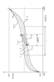
- the SOC-OCV characteristic (full charge characteristic) 5-1 curve when charging from the fully discharged state to the fully charged state and the discharge from the fully charged state to the fully discharged state are performed.
- the SOC-OCV characteristic region surrounded by the curve of the SOC-OCV characteristic (complete discharge characteristic) 5-2 the SOC-OCV characteristic 1 that passes through the points of different SOC values for each OCV value 1 -1,1-2,1-3 are newly added.
- the newly added SOC-OCV characteristics 1-1, 1-2, and 1-3 include 0% and 100% OCV voltages of 3.0V and 4% in the full charge characteristic 5-1 and the full discharge characteristic 5-2. .1V passes through the point, but does not intersect at other points, and is added to divide the SOC-OCV characteristic region surrounded by the full charge characteristic 5-1 and complete discharge characteristic 5-2 almost evenly. To do.
- the SOC-OCV characteristic table for mapping and storing the correspondence relationship between the SOC and the OCV includes a full charge characteristic 5-1, a complete discharge characteristic 5-2, and newly added SOC-OCV characteristics 1-1, 1-2, The correspondence relationship between each SOC 1-3 and OCV 1-3 is mapped and stored.
- FIG. 1 shows an example in which three are added.
- the number of added SOC-OCV characteristics is not limited to three. It can be appropriately increased or decreased depending on the characteristics of the battery and the required SOC estimation accuracy, and by adding at least one, the accuracy of the SOC can be improved as compared with the conventional case.
- an embodiment in which three are added will be described.
- the estimation of the SOC is based on three newly added SOC-OCV characteristics 1-1, 1-2 and 1-3, and a total of five SOC-OCV characteristics including a full charge characteristic 5-1 and a complete discharge characteristic 5-2.
- the SOC-OCV characteristic 1-2 is the average characteristic of the full charge characteristic 5-1 and the complete discharge characteristic 5-2
- the SOC-OCV characteristic 1-1 is the full charge characteristic 5-1 and the average characteristic 1.
- the SOC-OCV characteristic 1-3 is an average characteristic of the complete discharge characteristic 5-2 and the average characteristic 1-2.
- Table 1 shows an example of an SOC-OCV characteristic table in which each SOC value corresponding to each OCV value is mapped for each of the five SOC-OCV characteristics.
- the SOC-OCV characteristic table simultaneously holds movement values assigned in association with the respective SOC-OCV characteristics.
- the position of the average characteristic 1-2 is set as the reference position
- the movement value of the average characteristic 1-2 is set to 0
- the movement value indicating the movement amount (deviation) from the average characteristic 1-2 is set to other values.
- the movement value of the full charge characteristic 5-1 is 1, the movement value of the complete discharge characteristic 5-2 is -1, and the average characteristic SOC-OVC characteristic 1-1 of the full charge characteristic 5-1 and the average characteristic 1-2. Is 0.5, and the movement value of the average characteristic SOC-OVC characteristic 1-3 of the complete discharge characteristic 5-2 and the average characteristic 1-2 is -0.5.
- the charge characteristic 1-4 of FIG. 1 is assumed to be a curve of the discharge characteristic 1-5 in FIG. 1 when discharged from the point P1 on the full charge characteristic 5-1 to the point P2 on the complete discharge characteristic 5-2. It is difficult to specify accurately.
- Movement amount previous movement value ⁇ SOC ⁇ movement coefficient ⁇ downward correction coefficient
- the initial value of the previous movement value is 1 when charging from the fully discharged state.
- the movement value of the full charge characteristic 5-1 is set to 1.
- the integrated current in the calculation of ⁇ SOC is the discharge amount. The current is positive and the charging current is negative.
- the movement coefficient is 1 / 8.1 as an example.
- the downward correction coefficient is 1 at the time of charging, and is determined depending on the characteristics of the secondary battery at the time of discharging.
- the movement coefficient will be described in detail.
- the SOC-OCV characteristics the difference between the SOC and the OCV varies depending on the area between the charge characteristics and the discharge characteristics.
- the complete discharge characteristic 5 is obtained in an area (area L shown as an example in FIG. 1) in which the deviation of the SOC value is the largest with respect to the same OCV value.
- the accumulated current amount at which the OCV fluctuates from the point -2 to the point of the full charge characteristic 5-1 is measured.
- the movement coefficient is a coefficient that normalizes the movement amount in correspondence with the movement value of the SOC-OCV characteristic, and indicates a change in movement value per 1% change in ⁇ SOC.
- the downward correction coefficient will be explained.
- the OCV shows a lower value on the discharge side than on the charge side, and even when the current accumulated amount is the same at the time of charging and discharging, the variation at the time of discharging is larger than that at the time of charging Become. Therefore, a downward correction coefficient is used to accelerate the amount of movement during discharge.
- the SOC is normally calculated by the following equation using the full charge capacity as the denominator and the accumulated current amount as the numerator.
- SOC initial SOC + current integrated amount / full charge capacity (Equation 3)
- the full charge capacity which is the denominator of the above equation, is Since it becomes smaller, the SOC fluctuation at the time of discharge becomes 10% or more. This fluctuation depends on the charge / discharge efficiency of the secondary battery and is a value specific to the battery.
- 1/10 of the known charge / discharge efficiency of 99.5% is used as the degree of influence on the downward correction, and 1.0005 is used. It can be determined as a downward correction factor.
- the number of divisions of the SOC-OCV characteristic area will be described.
- the three SOC-OCV characteristics 1-1, 1-2, and 1-3 are included in the SOC-OCV characteristic region surrounded by the full charge characteristic 5-1 and the complete discharge characteristic 5-2.
- a curve was added to divide the SOC-OCV characteristic area into four.
- the number of divisions depends on the required accuracy. Now, assuming that the required accuracy is 1%, and the maximum SOC deviation is 4% between the full charge characteristic 5-1 and the complete discharge characteristic 5-2, the area of the maximum deviation 4% is divided into four. Thus, by estimating the SOC with the SOC-OCV characteristics in increments of 1%, it is possible to perform SOC estimation with a required accuracy of 1%.
- the SOC-OCV characteristic table discrete OCV values are arranged in the horizontal direction, and SOC values are mapped to the respective OCV values.
- an intermediate value finer than the value of each OCV in the SOC-OCV characteristic table is detected.
- the SOC value can be supplemented by linear interpolation.
- the vertical movement value of the SOC-OCV characteristic table is related to the number of divisions described above, the linear interpolation of the SOC-OCV characteristic is not performed for the movement value.
- the movement amount of the SOC-OCV characteristic will be described in detail.
- a total of five SOC-OCV characteristics used for estimating the SOC are prepared, and a movement amount based on current integration by charging / discharging is calculated.
- the movement value is calculated. Selects the one close to the amount of movement.
- the movement amount is ⁇ 1 or more, it is handled as a movement value ⁇ 1. Therefore, the SOC-OCV characteristic used for SOC estimation does not extend beyond the region surrounded by the full charge characteristic 5-1 and the complete discharge characteristic 5-2, and the estimated value of SOC is deteriorated from the conventional estimated value. There is nothing.
- the SOC-OCV characteristic 1-1 having a movement value of 0.5 is used.
- the SOC-OCV characteristic table of Table 1 the SOC-OCV characteristic of the movement value 0.5 is referred to, and the OCV value is calculated. The SOC is obtained.
- the secondary battery changes in SOC-OCV characteristics due to aging. Therefore, it is necessary to correct the mapping data of the SOC-OCV characteristic according to the deterioration state. In order to perform this correction, a deterioration map for each deterioration year is prepared.
- Degradation coefficients corresponding to the OCV value are arranged in the horizontal direction of the deterioration map, and deterioration coefficients are arranged in the vertical direction according to the years of deterioration.
- the deterioration is corrected by multiplying the mapping data of the SOC-OCV characteristic by the coefficient of the deterioration map.
- the deterioration map is stored for each SOC-OCV characteristic 5-1, 5-2, 1-1, 1-2, 1-3.
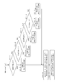
- FIG. 2 and 3 show examples of the flow for selecting the above-mentioned SOC-OCV characteristics and selecting the deterioration map.
- S2-1, S2-2 it is determined whether the secondary battery is being charged or discharged.
- the amount of movement due to current integration at the time of charging is calculated by setting the downward correction coefficient of the above (Equation 2) to 1 (S2-3).
- the amount of movement due to current integration during discharging is calculated by setting the downward correction coefficient in the above-described (Equation 2) to 1.0005 (S2-4). If it is neither charging nor discharging, the movement amount is not changed, and the previous movement amount is held (S2-5).
- the movement amount is less than ⁇ 0.75, more than ⁇ 0.75 and less than ⁇ 0.25, more than ⁇ 0.25 and less than 0.25, and more than 0.25 and less than 0.75 (S2 -6 to S2-9).
- the SOC-OCV characteristic of movement value -1 is selected (S2-10).
- the SOC-OCV characteristic having a movement value of -0.5 is selected (S2-11).
- the SOC-OCV characteristic with the movement value 0 is selected (S2-12).
- the SOC-OCV characteristic having a movement value of 0.5 is selected (S2-13). If the amount of movement is other than that, the SOC-OCV characteristic of the movement value 1 is selected (S2-14).
- the deterioration of the secondary battery is estimated. As in the example shown in FIG. 3, it is determined whether the deterioration time of the secondary battery is 0 year, 1 year, n year, or 9 year (S3-1 to S3-4). If the deterioration year is 0 years, select the deterioration map of year 0 (S3-5). If the deterioration year is 1 year, select the deterioration map of year 1 (S3-6), and the deterioration year is n years. If the deterioration year is 9 years, select the deterioration map of the year 9 (S3-8), otherwise select the deterioration map of the year 10 (S3-7). (S3-9). FIG. 3 shows an example in which the deterioration map is prepared for 10 years, but how many years the deterioration map is prepared is appropriately selected depending on the performance of the secondary battery and the like.
- a deterioration coefficient that reduces the SOC value of the SOC-OCV characteristic table due to aging deterioration is mapped.
- the SOC-OCV characteristic table corresponding to the deterioration year is created by multiplying the deterioration coefficient of the deterioration map selected according to the deterioration year by the SOC value of the SOC-OCV characteristic table (S3-10).
- the SOC value is estimated based on the measured OCV value using the SOC-OCV characteristic selected by the movement amount according to the flow of FIG. 2 and the deterioration estimated by the flow of FIG. 3 (S-11). It should be noted that the age of deterioration can be determined by deterioration estimation using a current value measured in synchronization with the battery voltage.
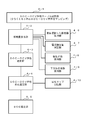
- FIG. 4 shows an example of a functional block configuration of the SOC estimation device that selects the SOC-OCV characteristics described above.
- the SOC estimation device includes a table storage unit 4-1, a movement amount calculation unit 4-2, an SOC-OCV characteristic selection unit 4-3, an SOC-OCV characteristic deterioration estimation unit 4-4, and an SOC estimation unit 4-5. .
- the SOC-OCV characteristic table storage unit 4-1 stores mapping data of at least one SOC-OCV characteristic that divides between the full charge characteristic 5-1 and the complete discharge characteristic 5-2.
- the movement amount calculation unit 4-2 includes a movement value held in the movement value holding unit 4-6 selected last time, a charge / discharge current integration amount measured by the current integration amount measurement unit 4-7, and a movement coefficient. Using the movement coefficient held in the holding unit 4-8 and the lower correction coefficient held in the lower correction coefficient holding unit 4-9, the movement amount of the SOC-OCV characteristic is calculated by the above-described (Equation 2). To do.
- the SOC-OCV characteristic selection unit 4-3 determines the movement value closest to the movement amount calculated by the movement amount calculation unit 4-2, and selects the SOC-OCV characteristic of the movement value.
- the SOC-OCV characteristic deterioration estimation unit 4-4 reads a deterioration map corresponding to the deterioration year of the secondary battery to be estimated from the deterioration map storage unit 4-10, and calculates a deterioration coefficient of the deterioration map of the SOC-OCV characteristic.
- the mapping data is multiplied to generate an SOC-OCV characteristic whose deterioration is estimated.
- the SOC estimator 4-5 uses the SOC-OCV characteristic selected by the SOC-OCV characteristic selector 4-3 and the deterioration estimated by the SOC-OCV characteristic deterioration estimator 4-4 to measure the measured OCV value. From this, the SOC value is estimated.
Landscapes
- Engineering & Computer Science (AREA)
- Chemical & Material Sciences (AREA)
- Chemical Kinetics & Catalysis (AREA)
- Manufacturing & Machinery (AREA)
- Power Engineering (AREA)
- General Chemical & Material Sciences (AREA)
- Electrochemistry (AREA)
- Sustainable Development (AREA)
- Sustainable Energy (AREA)
- Life Sciences & Earth Sciences (AREA)
- Mechanical Engineering (AREA)
- Transportation (AREA)
- General Physics & Mathematics (AREA)
- Materials Engineering (AREA)
- Physics & Mathematics (AREA)
- Charge And Discharge Circuits For Batteries Or The Like (AREA)
- Secondary Cells (AREA)
- Tests Of Electric Status Of Batteries (AREA)
Abstract
満充電特性と、完全放電特性と、該満充電特性と完全放電特性との間の領域を分割する少なくとも1本のSOC-OCV特性とを含む複数のSOC-OCV特性のテーブル4-1を用意し、各SOC-OCV特性に移動値を付与する。充放電による電流積算量と、該充放電の直前に用いたSOC-OCV特性の移動値とに基づいて、該電流積算量に応じたSOC-OCV特性の移動量を移動量算出部4-2で算出し、該移動量に最も近い移動値を判定し、該移動値のSOC-OCV特性をSOC-OCV特性選択部4-3で選択し、該選択されたSOC-OCV特性を使用して、測定されたOCVの値からSOCの値をSOC推定4-5で推定する。
Description
本発明は、二次電池の充電状態推定装置及び充電状態推定方法に関し、特に充電状態(SOC:State of Charge)を、二次電池の開放電圧(OCV:Open Circuit Voltage)から、SOC-OCV特性を基に推定する際に、該推定誤差を低減する充電状態推定装置及び充電状態推定方法に関する。
リチウムイオンバッテリ等の二次電池を用いる自動車や電装機器等の装置において、その性能は、使用する二次電池の性能に大きく影響されるため、該二次電池の充放電状態を効率的に精度良く制御し、該二次電池の性能を高く維持することが要求されている。
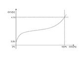
このような二次電池において、充電状態(以下「SOC」という)は、該二次電池の開放電圧(以下「OCVという)から、SOCとOCVとの相関関係を示すSOC-OCV特性を基に推定することができる。図5Aは、SOC-OCV特性の一例を示している。
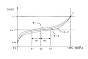
SOC-OCV特性は、二次電池の内部抵抗や分極現象等の影響により、充電時と放電時とで特性曲線が変動する特性を有する。図5Bは、SOC-OCV特性の変動の一例を示す。図5Bにおいて、5-1は、完全放電状態から満充電状態まで充電したときのSOC-OCV特性(以下「満充電特性」という)を示す。また、5-2は、満充電状態から完全放電状態まで放電したときのSOC-OCV特性(以下「完全放電特性」という)を示す。
完全放電と満充電との間の状態で、二次電池の充電又は放電が行われたとき、SOC-OCV特性として、どのような特性曲線を辿るかは、過去の充放電の実施状況に依存し、各充放電の実施に対してSOC-OCV特性がどのような特性曲線となるかを厳密に特定することは困難である。
そのため、一般に、SOC-OCV特性として、満充電特性5-1と完全放電特性5-2との間の平均的な値を取った平均特性5-3を用いて、SOCの推定が行われる。図5Aは、このSOC-OCV特性の平均特性5-3の一例を示している。
充放電の実施によってSOC-OCV特性がどのような特性曲線となるかを正確に定めることは困難であるが、完全放電状態と満充電状態の中間の通常の使用中の充電状態における充放電時のSOC-OCV特性は、図6Aに示すように、満充電特性5-1と、完全放電特性5-2との間を辿る。
充放電が繰り返された場合、OCVは図6Bに示すように、満充電特性5-1と完全放電特性5-2との間で変動する。SOC-OCV特性は、傾きが一様ではなく、満充電状態(SOC=100%)又は完全放電状態(SOC=0%)の近傍区域では、特性曲線の傾きが急峻であるのに対して、その中間の通常の使用中の充電状態の区域では、該特性曲線の傾きは緩やかである。
そのため、充放電電流の積算量が同じであっても、充電状態(SOC)の区域によって、また、充電か放電かの実施状況によって、OCVの値の変動量は異なるものとなり、電流積算量によりOCVの値の変動量を定めることは困難である。
このようにOCVとSOCとの関係が充放電の履歴により変化してしまう二次電池(大ヒステリシス電池)に対して、精度良く電池制御を行う先行技術は、例えば下記の特許文献1~3等により知られている。
該特許文献1に記載の技術は、基準状態電池電圧が常用最小電圧値を超えて低下した場合に、常用最大電圧値近傍まで充電し、その後、目標電圧値近傍まで放電する方法に関するものである。
特許文献2に記載の技術は、二次電池の充放電によって生じるヒステリシス特性に着目し、該二次電池の充放電量の積算に基づいて求めたSOCの今回値と所定の目標SOC値との差を収束させる充放電制御に係るものである。
特許文献3等に記載の技術は、充電後のOCVと放電後のOCVとが異なる二次電池に対して、充電後のOCVと放電後のOCVを区別して測定し、SOC-OCV特性を示す充電率算出用テーブルとして、充電側テーブルと放電側テーブルを選択的に適用し、充電率を精度良く算出する技術に係るものである。
一般に、測定したOCVの値からSOCの値を推定する際に、図5Aに示すようなSOC-OCV特性の平均特性が使用されるが、この平均特性を使用して推定したSOCの値は、実際には、上述の充放電の履歴によるSOC-OCV特性の変動による誤差を含む推定を行っていることになる。
即ち、図5Bに示すように、測定したOCVの値Vpに対して、SOC-OCV特性の平均特性5-3を使用した場合、SOCの推定値はSpとなるが、実際のSOCの取り得る値としては、満充電特性5-1におけるSOCの値S1と、完全放電特性5-2におけるSOC値S2との間の何れか値であり、SOCの推定値Spは、最大でそれらとの差分であるE1又はE2の誤差を含むものとなる。
そのため、測定したOCVの値でSOC-OCV特性の平均特性5-3によりSOCの値を算出すると、殆どの場合、該SOCの値は真値とはならない。しかし、SOC-OCV特性の変動に対して、SOCの真値がいずれの値となるかを厳密に特定することは極めて困難であり、事実上不可能に近い。
SOCの真値が特定されないことによる影響として、
(1)二次電池の充放電制御を適正に行うことができず、二次電池の使用上の安全性を低下させることとなる。
(2)SOCの推定誤差によって、使用可能な電気エネルギーの範囲を過少評価してしまう。
(3)電力制御における判定などにおいて、SOCの値を使用して行う判定の正確性が損なわれ、電力制御などを適正に行うことができなる。
などの問題が生じる。
(1)二次電池の充放電制御を適正に行うことができず、二次電池の使用上の安全性を低下させることとなる。
(2)SOCの推定誤差によって、使用可能な電気エネルギーの範囲を過少評価してしまう。
(3)電力制御における判定などにおいて、SOCの値を使用して行う判定の正確性が損なわれ、電力制御などを適正に行うことができなる。
などの問題が生じる。
上記課題に鑑み、本発明は、充放電の実施によるSOC-OCV特性の変動に対して、充放電の実施状況に応じて真値により近いSOC-OCV特性を推定し、該推定したSOC-OCV特性を用いてSOCの値を推定し、SOCの推定誤差を低減することができる充電状態推定装置及び充電状態推定方法を提供する。
本発明の一つの形態である充電状態推定装置は、OCVからSOC-OCV特性を基にSOCを推定する充電状態推定装置において、満充電特性と、完全放電特性と、該満充電特性と完全放電特性との間の領域を分割する少なくとも1本のSOC-OCV特性とを含む複数のSOC-OCV特性をマッピングし、かつ、各SOC-OCV特性に対して移動値を付与したSOC-OCV特性テーブルと、充放電による電流積算量と、該充放電の直前に用いられたSOC-OCV特性の移動値とに基づいて、該電流積算量に応じたSOC-OCV特性の移動量を算出する移動量算出手段と、前記移動量算出手段で算出された移動量に最も近い移動値を判定し、該移動値のSOC-OCV特性を、前記複数のSOC-OCV特性の中から選択するSOC-OCV特性選択手段と、前記SOC-OCV特性選択手段で選択されたSOC-OCV特性を使用し、測定されたOCVの値からSOCの値を推定するSOC推定手段と、を備えたものである。
これにより、充放電電流の電流積算量に応じて変動するSOC-OCV特性の移動量を推測し、予め用意した複数のSOC-OCV特性の中から、該移動量に最も近いSOC-OCV特性を選択し、該SOC-OCV特性を用いて、SOCの推定を行うにより、SOC推定の誤差を低減することが可能となる。
また、前記移動量算出手段は、放電による電流積算に対して、充電による電流積算に比べて、前記SOC-OCV特性の移動量を下方へ移動させる演算を行うものである。これにより、放電時の電流積算量に対して、充電時に比べて移動量を下方へ修正し、より精度良くSOC-OCV特性を選択することが可能となる。
また、前記SOC-OCV特性選択手段で選択されたSOC-OCV特性に、前記二次電池の劣化年数に応じた劣化係数を乗じたSOC-OCV特性を生成するSOC-OCV特性劣化推定手段を備え、前記SOC推定手段は、前記SOC-OCV特性劣化推定手段で生成されたSOC-OCV特性を用いて、前記SOCの値を推定するものである。これにより、二次電池の経年劣化に応じた、精度の高いSOCの値を推定することが可能となる。
本発明によれば、充放電の実施によるSOC-OCV特性の変動に対して、充放電の実施状況に応じて真値により近いSOC-OCV特性を推定し、該推定したSOC-OCV特性を用いて、SOCの値を推定することにより、SOCの推定誤差を低減することができる。
本発明の実施形態を以下の実施例に基づいて詳しく説明する。本発明では、図1に示すように、完全放電状態から満充電状態まで充電したときのSOC-OCV特性(満充電特性)5-1の曲線と、満充電状態から完全放電状態まで放電したときのSOC-OCV特性(完全放電特性)5-2の曲線とで囲まれるSOC-OCV特性領域内に、各OCVの値に対して、それぞれ異なるSOCの値の点を通過するSOC-OCV特性1-1,1-2,1-3を新たに追加する。
新たに追加したSOC-OCV特性1-1,1-2,1-3は、満充電特性5-1及び完全放電特性5-2におけるSOCの0%及び100%のOCV電圧3.0V及び4.1Vの点を通過するが、それ以外の点で交差することは無く、満充電特性5-1及び完全放電特性5-2で囲まれるSOC-OCV特性領域をほぼ均等に分割するように追加する。
SOCとOCVとの対応関係をマッピングして記憶するSOC-OCV特性テーブルは、満充電特性5-1、完全放電特性5-2及び新たに追加したSOC-OCV特性1-1,1-2,1-3のそれぞれのSOCとOCVとの対応関係をマッピングして記憶する。
新たに追加するSOC-OCV特性1-1,1-2,1-3として、図1では3本追加した例を示しているが、追加する本数は3本に限られるものではなく、二次電池の特性や、要求されるSOCの推定精度によって適宜増減することができ、少なくとも1本を追加することによって、従来に比べてSOCの精度を向上させることができる。以下では、3本追加した実施例について説明する。
SOCの推定は、新たに追加した3本のSOC-OCV特性1-1,1-2,1-3と、満充電特性5-1及び完全放電特性5-2の合計5本のSOC-OCV特性の何れかを用いて行う。ここで、SOC-OCV特性1-2は、満充電特性5-1と完全放電特性5-2との平均特性とし、SOC-OCV特性1-1は、満充電特性5-1と平均特性1-2との平均特性とし、SOC-OCV特性1-3は、完全放電特性5-2と平均特性1-2との平均特性とする。
この5本のSOC-OCV特性のそれぞれについて、各OCVの値に対応する各SOCの値をマッピングしたSOC-OCV特性テーブルの一例を表1に示す。

そのため、満充電特性5-1の移動値を1、完全放電特性5-2の移動値を-1、満充電特性5-1と平均特性1-2との平均特性SOC-OVC特性1-1の移動値を0.5、完全放電特性5-2と平均特性1-2との平均特性SOC-OVC特性1-3の移動値を-0.5とする。
この5本のSOC-OCV特性に対して、充放電により二次電池に入出力される電流の積算によって、OCVの値がSOC-OCV特性領域内をどのように移動し、SOCの推定に用いるSOC-OCV特性がどのように移動するかを推測する。そして推測した移動値のSOC-OCV特性を用いてSOCを推定することにより、SOCの推定誤差を低減する。
SOC-OCV特性における通常使用状態の中央部の区域で、完全放電特性5-2上の点P2から満充電特性5-1上の点P1まで充電したとき、図1の充電特性1-4の曲線となり、満充電特性5-1上の点P1から完全放電特性5-2上の点P2まで放電したとき、図1の放電特性1-5の曲線となることが想定されるが、その曲線を正確に特定することは困難である。
そこで、SOC-OCV特性の移動値が最小値(=-1)から最大値(=+1)まで変化する点P2から点P1までのSOCの変化量ΔSOCを予め測定し、この変化量ΔSOCに対するSOC-OCV特性の移動値の最大変化幅(=2)の比を移動係数として算出しておく。なお、放電時は、充電時に比べて、同一の変化量ΔSOCに対して、OCVの変化量が大きくなることから、放電時には、移動値を下方に修正するための下方修正係数を移動係数に乗じる。
充放電により二次電池に入出力される電流積算量によって変動するSOCの変化量ΔSOCは、
ΔSOC=電流積算量÷満容量・・・(式1)
により算出される。
ΔSOC=電流積算量÷満容量・・・(式1)
により算出される。
従って、二次電池に入出力される電流積算により変動するSOC-OCV特性の移動量は、以下の式により算出される。
移動量=前回の移動値-ΔSOC×移動係数×下方修正係数・・・(式2)
上記(式2)により算出した移動量に対して、離散値である移動値のうち、どの移動値が該移動量に最も近いかを判定し、最も近い移動値を選定する。
移動量=前回の移動値-ΔSOC×移動係数×下方修正係数・・・(式2)
上記(式2)により算出した移動量に対して、離散値である移動値のうち、どの移動値が該移動量に最も近いかを判定し、最も近い移動値を選定する。
(式2)において、前回の移動値の初期値は、完全放電状態から充電中の場合は1である。(満充電状態である場合は、満充電特性5-1に近い値になるので、満充電特性5-1の移動値である1とする。)また、ΔSOCの算出における電流積算量は、放電電流をプラス、充電電流をマイナスとしている。移動係数は、以下に説明するが一例として1/8.1とする。また、下方修正係数は、充電時には1であり、放電時には、二次電池の特性に依存して決定されるが、一例として1.0005とする。
ここで、移動係数について詳述する。SOC-OCV特性は、充電特性と放電特性とでSOCやOCVの乖離がそれらの区域に応じて変化する。本実施例では、OCVの値からSOCの値を推定するため、同一のOCVの値に対してSOCの値の乖離が最も大きい区域(図1で一例として示す区域L)で、完全放電特性5-2の点から満充電特性5-1の点へOCVが変動する電流積算量を測定する。
その電流積算量に相当するSOCの変化量ΔSOCを算出し、一例として16.2%を得る。即ち、16.2%充電してSOCを変化させると、完全放電特性5-2から満充電特性5-1へ移動することとなるため、連続して16.2%充電すれば、移動値が-1から+1へと変化し、その変化幅は2となることから、移動係数として2/16.2=1/8.1が決定される。移動係数はSOC-OCV特性の移動値に対応させて前記移動量を正規化する係数であり、△SOCの変化1%あたりの移動値の変化を示す。
次に下方修正係数について説明する。SOC-OCV特性において、OCVは放電側の方が充電側より低い値を示し、充電時と放電時とで同じ電流積算量であっても、放電時の方が充電時より変動が大きいこととなる。そこで、放電中の移動量を加速させるために下方修正係数を使用する。
SOCは、通常、満充電容量を分母に、電流積算量を分子にして、以下の式により算出される。
SOC=初期SOC+電流積算量÷満充電容量・・・(式3)
しかし、放電容量は充電容量より少ないため、充電時のSOC変化10%の電流積算量と同じだけの電流積算量を放電した場合、放電時は上式の分母である満充電容量が、充電時より小さくなるため、放電時のSOC変動は10%以上になる。この変動は二次電池の充放電効率に左右され、電池特有の値であるが、公知の充放電効率99.5%の1/10を下方修正への影響度として使用し、1.0005を下方修正係数として決定することができる。
SOC=初期SOC+電流積算量÷満充電容量・・・(式3)
しかし、放電容量は充電容量より少ないため、充電時のSOC変化10%の電流積算量と同じだけの電流積算量を放電した場合、放電時は上式の分母である満充電容量が、充電時より小さくなるため、放電時のSOC変動は10%以上になる。この変動は二次電池の充放電効率に左右され、電池特有の値であるが、公知の充放電効率99.5%の1/10を下方修正への影響度として使用し、1.0005を下方修正係数として決定することができる。
次にSOC-OCV特性領域の分割数について説明する。上述の実施例では、満充電特性5-1と完全放電特性5-2とで囲まれるSOC-OCV特性領域内に、3本のSOC-OCV特性1-1,1-2,1-3の曲線を追加して、該SOC-OCV特性領域を4つに分割した。
分割数を幾つにするかは、要求される精度による。今、要求精度が1%であるとし、満充電特性5-1と完全放電特性5-2とでSOCの最大乖離が4%であったとすると、該最大乖離4%の領域を4分割することにより、1%刻みのSOC-OCV特性でSOCを推定することにより、要求精度1%のSOC推定を行うことが可能となる。
電流センサやA/D変換の誤差などによって発生する電流積算誤差が1%を超える場合には、追加するSOC-OCV特性の本数を低減する。例えば、最大乖離4%、電流積算誤差が1.5%よりも大きい場合、SOC-OCV特性の合計本数を4として分割数を3に減らし、最大乖離4%の領域を3分割して、精度1.3%(=4%÷3)とする。
次にSOC-OCV特性テーブルについて詳述する。SOC-OCV特性テーブルは、横方向に離散的なOCVの各値を配列し、該OCVの各値に対してSOCの値をそれぞれマッピングしている。二次電池の電圧を測定した場合、SOC-OCV特性テーブルの各OCVの値よりもきめ細かい中間値が検出される。このOCVの中間値に対しては、線形補間によりSOCの数値を補うことができる。一方、SOC-OCV特性テーブルの縦方向の移動値に関しては、前述した分割数に係るため、移動値についてSOC-OCV特性の線形補間は行わない。
次にSOC-OCV特性の移動量について詳述する。上述の実施例では、SOCの推定に用いるSOC-OCV特性として合計で5本用意し、充放電による電流積算による移動量を算出し、用意した5本のSOC-OCV特性のうち、その移動値が該移動量に近いものを選択する。なお、移動量が±1以上の場合は、移動値±1として扱う。そのため、SOCの推定に用いるSOC-OCV特性は、満充電特性5-1及び完全放電特性5-2で囲まれる領域を超えて広がることは無く、SOCの推定値が従来の推定値より劣化することは無い。
ここで具体的な数値例を用いて上述の動作を説明する。今、図1の点Qを開始点として放電が行われたとする。点Qは、満充電特性5-1(移動値:+1)上に有り、OCVが4.047V、SOCが95.02%であるとする(表1参照)。そして放電によるSOCの変化量ΔSOCが前述の(式1)により4.98%として算出されたとする。
すると、前述の(式2)により、移動量は、
移動量=1-5×(1/8.1)×1.0005=0.3824
として算出される。
移動量=1-5×(1/8.1)×1.0005=0.3824
として算出される。
この移動量0.3824に対して、離散値である移動値(+1,+0.5,0,-0.5,-1)のうち、どの移動値が最も近いかを判定し、最も近い移動値+0.5を選定する。従って、移動値0.5のSOC-OCV特性1-1を用いることとし、表1のSOC-OCV特性テーブルのうち、移動値0.5のSOC-OCV特性を参照して、OCVの値からSOCを求めることとなる。
次に二次電池の経年劣化について説明する。二次電池は経年劣化によってSOC-OCV特性が変化する。従って、劣化状態に応じて、SOC-OCV特性のマッピングデータを補正する必要がある。この補正を行うために、劣化年数毎の劣化マップを用意する。
劣化マップの一例を表2に示す。
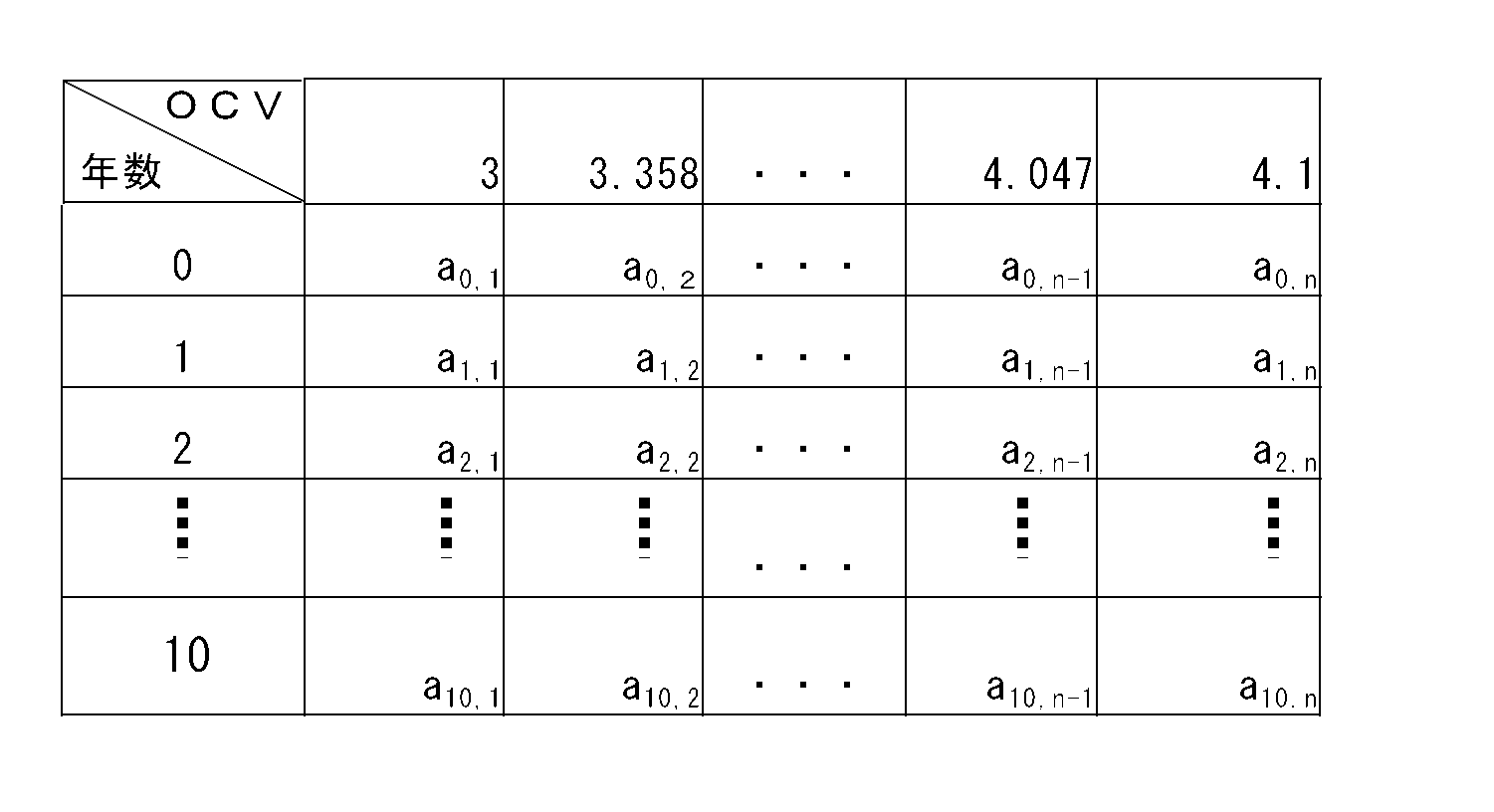
劣化マップの横方向にはOCVの値に応じた劣化係数を配列し、縦方向には劣化年数に応じた劣化係数配列する。該劣化マップの係数をSOC-OCV特性のマッピングデータに乗じることにより、劣化に対する補正を行う。劣化マップは各SOC-OCV特性5-1、5-2、1-1、1-2、1-3毎に保管することとする。
上述のSOC-OCV特性の選定及び劣化マップの選定のフローの例を図2及び図3に示す。図2に示すように、二次電池が充電中か放電中かを判定する(S2-1,S2-2)。充電中の場合、充電時の電流積算による移動量を、前述の(式2)の下方修正係数を1に設定して算出する(S2-3)。放電中の場合、放電時の電流積算による移動量を、前述の(式2)の下方修正係数を1.0005に設定して算出する(S2-4)。充電中でも放電中でもない場合、移動量に変動が無いので、前回の移動量を保持する(S2-5)。
次に移動量が-0.75未満か、-0.75以上-0.25未満か、-0.25以上0.25未満か、0.25以上0.75未満か、を判定する(S2-6~S2-9)。移動量が-0.75未満のとき移動値-1のSOC-OCV特性を選択(S2-10)する。移動量が-0.75以上-0.25未満のとき移動値-0.5のSOC-OCV特性を選択する(S2-11)。移動量が-0.25以上0.25未満のとき移動値0のSOC-OCV特性を選択する(S2-12)。移動量が0.25以上0.75未満のとき移動値0.5のSOC-OCV特性を選択する(S2-13)。移動量がそれ以外の場合、移動値1のSOC-OCV特性を選択する(S2-14)。
次に二次電池の劣化推定を行う。図3に示す例のように、二次電池の劣化年数が0年か、1年か、n年か、9年かを判定する(S3-1~S3-4)。劣化年数が0年の場合、年数0の劣化マップを選択し(S3-5)、劣化年数が1年の場合、年数1の劣化マップを選択し(S3-6)、劣化年数がn年の場合、年数nの劣化マップを選択し(S3-7)、劣化年数が9年の場合、年数9の劣化マップを選択し(S3-8)、それ以外の場合、年数10の劣化マップを選択する(S3-9)。なお、図3では、劣化マップを10年分用意する例を示しているが、劣化マップを何年分用意するかは、二次電池の性能等に依存して適宜選定する。
劣化マップには、SOC-OCV特性テーブルのSOCの値を、経年劣化により低減させる劣化係数をマッピングしておく。劣化年数に応じて選択した劣化マップの劣化係数を、SOC-OCV特性テーブルのSOCの値に掛け合せて、劣化年数に対応したSOC-OCV特性テーブルを作成する(S3-10)。
前述の図2のフローによる移動量で選択し、図3のフローで劣化推定したSOC-OCV特性を用い、測定したOCVの値を基に、SOCの値を推定する(S-11)。なお、劣化年数の決定は、電池電圧と同期して測定される電流値を用いた劣化推定により算定することができる。
上述のSOC-OCV特性の選択を行うSOC推定装置の機能ブロック構成例を図4に示す。SOC推定装置は、テーブル記憶部4-1、移動量算出部4-2、SOC-OCV特性選択部4-3、SOC-OCV特性劣化推定部4-4、及びSOC推定部4-5を備える。
SOC-OCV特性テーブル記憶部4-1は、満充電特性5-1と完全放電特性5-2のほかに、その間を分割する少なくとも1本のSOC-OCV特性のマッピングデータを記憶する。移動量算出部4-2は、前回選択した移動値の保持部4-6に保持された移動値と、電流積算量測定部4-7で測定された充放電の電流積算量と、移動係数保持部4-8に保持された移動係数と、下方修正係数保持部4-9に保持された下方修正係数とを用いて、前述の(式2)により、SOC-OCV特性の移動量を算出する。
SOC-OCV特性選択部4-3は、移動量算出部4-2で算出された移動量に最も近い移動値を判定し、該移動値のSOC-OCV特性を選択する。SOC-OCV特性劣化推定部4-4は、SOC推定対象の二次電池の劣化年数に応じた劣化マップを劣化マップ記憶部4-10から読み出し、該劣化マップの劣化係数をSOC-OCV特性のマッピングデータに乗算し、劣化推定したSOC-OCV特性を生成する。
SOC推定部4-5は、SOC-OCV特性選択部4-3で選択され、SOC-OCV特性劣化推定部4-4で劣化推定されたSOC-OCV特性を用いて、測定されたOCVの値からSOCの値を推定する。
以上、本発明のSOC推定装置及びSOC推定方法の実施形態について実施例を基に説明したが、本発明は、上述の実施の形態に限定されるものではなく、本発明の要旨を逸脱しない範囲内で種々の構成又は実施形態を取ることができる。
Claims (5)
- 二次電池の開放電圧(OCV)からSOC-OCV特性を基に充電状態(SOC)を推定する充電状態推定装置において、
完全放電状態から満充電状態まで充電したときのSOC-OCV特性(以下「満充電特性」という)と、満充電状態から完全放電状態まで放電した時のSOC-OCV特性(以下「完全放電特性」という)と、該満充電特性と完全放電特性との間の領域を分割する少なくとも1本のSOC-OCV特性とを含む複数のSOC-OCV特性をマッピングし、かつ、各SOC-OCV特性に対して移動値を付与したSOC-OCV特性テーブルと、
充放電による電流積算量と、該充放電の直前に用いられたSOC-OCV特性の移動値とに基づいて、該電流積算量に応じたSOC-OCV特性の移動量を算出する移動量算出手段と、
前記移動量算出手段で算出された移動量に最も近い移動値を判定し、該移動値のSOC-OCV特性を、前記複数のSOC-OCV特性の中から選択するSOC-OCV特性選択手段と、
前記SOC-OCV特性選択手段で選択されたSOC-OCV特性を使用し、測定されたOCVの値からSOCの値を推定するSOC推定手段と、
を備えたことを特徴とする充電状態推定装置。 - 前記移動量算出手段は、放電による電流積算に対して、充電による電流積算に比べて、前記SOC-OCV特性の移動量を下方へ移動させる演算を行うことを特徴とする請求項1に記載の充電状態推定装置。
- 前記移動量算出手段は、充放電の電流積算によるSOCの変化分に、前記SOC-OCV特性の移動値に対応させて前記移動量を正規化する移動係数を乗算し、かつ、放電時に該乗算の値にSOC-OCV特性を下方に移動させる下方修正係数を乗算し、更に、該乗算の値の分だけ、前記充放電の直前に用いたSOC-OCV特性の移動値を増減させて、前記移動量を算出することを特徴とする請求項1に記載の充電状態推定装置。
- 前記SOC-OCV特性選択手段で選択されたSOC-OCV特性に、前記二次電池の劣化年数に応じた劣化係数を乗じたSOC-OCV特性を生成するSOC-OCV特性劣化推定手段を備え、前記SOC推定手段は、前記SOC-OCV特性劣化推定手段で生成されたSOC-OCV特性を用いて、前記SOCの値を推定することを特徴とする請求項1乃至3の何れかに記載の充電状態推定装置。
- 二次電池の開放電圧(OCV)からSOC-OCV特性を基に充電状態(SOC)を推定する充電状態推定方法において、
完全放電状態から満充電状態まで充電したときのSOC-OCV特性(以下「満充電特性」という)と、満充電状態から完全放電状態まで放電した時のSOC-OCV特性(以下「完全放電特性」という)と、該満充電特性と完全放電特性との間の領域を分割する少なくとも1本のSOC-OCV特性とを含む複数のSOC-OCV特性をマッピングし、かつ、各SOC-OCV特性に対して移動値を付与したSOC-OCV特性テーブルを用い、
充放電による電流積算量と、該充放電の直前に用いられたSOC-OCV特性の移動値とに基づいて、該電流積算量に応じたSOC-OCV特性の移動量を算出し、
前記算出された移動量に最も近い移動値を判定し、該移動値のSOC-OCV特性を、前記複数のSOC-OCV特性の中から選択し、
前記選択されたSOC-OCV特性を使用し、測定されたOCVの値からSOCの値を推定することを特徴とする充電状態推定方法。
Applications Claiming Priority (2)
| Application Number | Priority Date | Filing Date | Title |
|---|---|---|---|
| JP2012204152A JP2014059206A (ja) | 2012-09-18 | 2012-09-18 | 充電状態推定装置及び充電状態推定方法 |
| JP2012-204152 | 2012-09-18 |
Publications (1)
| Publication Number | Publication Date |
|---|---|
| WO2014045706A1 true WO2014045706A1 (ja) | 2014-03-27 |
Family
ID=50341032
Family Applications (1)
| Application Number | Title | Priority Date | Filing Date |
|---|---|---|---|
| PCT/JP2013/069839 Ceased WO2014045706A1 (ja) | 2012-09-18 | 2013-07-23 | 充電状態推定装置及び充電状態推定方法 |
Country Status (2)
| Country | Link |
|---|---|
| JP (1) | JP2014059206A (ja) |
| WO (1) | WO2014045706A1 (ja) |
Cited By (15)
| Publication number | Priority date | Publication date | Assignee | Title |
|---|---|---|---|---|
| WO2019017411A1 (ja) * | 2017-07-19 | 2019-01-24 | 株式会社Gsユアサ | 推定装置、蓄電装置、推定方法、及びコンピュータプログラム |
| JP2019020413A (ja) * | 2017-07-19 | 2019-02-07 | 株式会社Gsユアサ | 推定装置、蓄電装置、推定方法、及びコンピュータプログラム |
| CN110462413A (zh) * | 2017-03-29 | 2019-11-15 | 株式会社杰士汤浅国际 | 蓄电量估计装置、蓄电模块、蓄电量估计方法、和计算机程序 |
| CN110476073A (zh) * | 2017-03-29 | 2019-11-19 | 株式会社杰士汤浅国际 | 蓄电量估计装置、蓄电模块、蓄电量估计方法、和计算机程序 |
| CN110988720A (zh) * | 2019-06-24 | 2020-04-10 | 宁德时代新能源科技股份有限公司 | 电池荷电状态确定方法、装置、管理系统以及存储介质 |
| CN111505511A (zh) * | 2020-04-30 | 2020-08-07 | 北京嘀嘀无限科技发展有限公司 | 一种电动汽车单体电芯容量测定方法、电子设备及存储介质 |
| US10761143B2 (en) | 2017-06-02 | 2020-09-01 | Gs Yuasa International Ltd. | Storage amount estimation device, energy storage module, storage amount estimation method, and computer program |
| CN111722118A (zh) * | 2020-06-22 | 2020-09-29 | 上海理工大学 | 一种基于soc-ocv优化曲线的锂离子电池soc估计方法 |
| WO2020259039A1 (zh) * | 2019-06-24 | 2020-12-30 | 宁德时代新能源科技股份有限公司 | 荷电状态修正方法及装置 |
| JP2021071415A (ja) * | 2019-10-31 | 2021-05-06 | 株式会社Gsユアサ | 蓄電量推定装置、蓄電量推定方法及びコンピュータプログラム |
| US11150303B2 (en) | 2017-06-02 | 2021-10-19 | Gs Yuasa International Ltd. | Management device, energy storage module, management method, and computer program |
| JP2021532336A (ja) * | 2019-06-24 | 2021-11-25 | 寧徳時代新能源科技股▲分▼有限公司Contemporary Amperex Technology Co., Limited | 電池の荷電状態の修正方法、装置、システム及び記憶媒体 |
| CN114035059A (zh) * | 2021-11-08 | 2022-02-11 | 东软睿驰汽车技术(沈阳)有限公司 | 显示soc精度的计算方法、装置和电子设备 |
| EP4123322A4 (en) * | 2020-03-16 | 2023-12-13 | Kabushiki Kaisha Toshiba | INFORMATION PROCESSING APPARATUS, INFORMATION PROCESSING METHOD, COMPUTER PROGRAM AND INFORMATION PROCESSING SYSTEM |
| FR3163167A1 (fr) * | 2024-06-11 | 2025-12-12 | Stellantis Auto Sas | Détermination d’une information représentative d’une variation d’état de charge d’une batterie rechargeable cellulaire d’un système |
Families Citing this family (21)
| Publication number | Priority date | Publication date | Assignee | Title |
|---|---|---|---|---|
| DE112014006399B4 (de) | 2014-02-25 | 2019-03-21 | Mitsubishi Electric Corporation | Ladezustandschätzvorrichtung für eine Sekundärbatterie |
| KR101696313B1 (ko) | 2014-10-24 | 2017-01-13 | 주식회사 엘지화학 | 이차전지의 퇴화에 따른 soc-ocv 프로파일 추정 방법 |
| JP6548387B2 (ja) * | 2014-12-15 | 2019-07-24 | 川崎重工業株式会社 | 二次電池の充電状態推定方法および推定装置 |
| KR101779941B1 (ko) | 2014-12-29 | 2017-09-19 | 주식회사 엘지화학 | 배터리 충전 상태 측정 장치 및 방법 |
| JP6930572B2 (ja) * | 2016-01-15 | 2021-09-01 | 株式会社Gsユアサ | 蓄電素子管理装置、蓄電素子モジュール、車両および蓄電素子管理方法 |
| JP6830318B2 (ja) | 2016-01-15 | 2021-02-17 | 株式会社Gsユアサ | 蓄電素子管理装置、蓄電素子モジュール、車両および蓄電素子管理方法 |
| JP2018153069A (ja) * | 2017-03-14 | 2018-09-27 | 株式会社豊田自動織機 | 電池パック |
| JP6822300B2 (ja) | 2017-04-27 | 2021-01-27 | トヨタ自動車株式会社 | 充電率推定方法および車載の電池システム |
| JP6866756B2 (ja) * | 2017-05-15 | 2021-04-28 | 株式会社豊田自動織機 | 充電率推定装置 |
| JP6907848B2 (ja) * | 2017-09-14 | 2021-07-21 | 株式会社豊田自動織機 | 電池パック |
| JP6988386B2 (ja) * | 2017-11-08 | 2022-01-05 | 株式会社Gsユアサ | 蓄電素子の管理装置、及び、管理方法 |
| JP6927009B2 (ja) * | 2017-12-12 | 2021-08-25 | トヨタ自動車株式会社 | 二次電池システムおよび二次電池のsoc推定方法 |
| KR102458526B1 (ko) | 2018-02-07 | 2022-10-25 | 주식회사 엘지에너지솔루션 | 배터리의 동작 상태에 따라 soc를 추정하는 장치 및 방법 |
| KR102452626B1 (ko) | 2018-03-07 | 2022-10-06 | 주식회사 엘지에너지솔루션 | Soc-ocv 프로파일 추정 방법 및 장치 |
| JP7174327B2 (ja) * | 2018-11-14 | 2022-11-17 | トヨタ自動車株式会社 | 二次電池の状態判定方法 |
| WO2020129478A1 (ja) | 2018-12-18 | 2020-06-25 | パナソニックIpマネジメント株式会社 | 電池状態推定装置、電池状態推定方法、及び電池システム |
| JP6826152B2 (ja) * | 2019-04-26 | 2021-02-03 | 川崎重工業株式会社 | 二次電池の充電状態推定方法および推定装置 |
| CN112130077B (zh) * | 2020-09-30 | 2021-11-02 | 东风汽车集团有限公司 | 一种不同工况下动力电池组的soc估算方法 |
| CN113655385B (zh) * | 2021-10-19 | 2022-02-08 | 深圳市德兰明海科技有限公司 | 锂电池soc估计方法、装置及计算机可读存储介质 |
| CN114264998A (zh) * | 2021-12-27 | 2022-04-01 | 傲普(上海)新能源有限公司 | 一种利用ocv-soc曲线矫正soc的方法 |
| KR20260050790A (ko) * | 2024-10-08 | 2026-04-15 | 주식회사 엘지에너지솔루션 | 전자 장치 및 그의 배터리 soc 추정 방법 |
Citations (2)
| Publication number | Priority date | Publication date | Assignee | Title |
|---|---|---|---|---|
| JP2000295775A (ja) * | 1999-04-05 | 2000-10-20 | Denso Corp | 電池の残存容量演算方式 |
| JP2003168489A (ja) * | 2001-11-30 | 2003-06-13 | Yuasa Corp | アルカリ蓄電池の充放電状態の検知方法 |
-
2012
- 2012-09-18 JP JP2012204152A patent/JP2014059206A/ja active Pending
-
2013
- 2013-07-23 WO PCT/JP2013/069839 patent/WO2014045706A1/ja not_active Ceased
Patent Citations (2)
| Publication number | Priority date | Publication date | Assignee | Title |
|---|---|---|---|---|
| JP2000295775A (ja) * | 1999-04-05 | 2000-10-20 | Denso Corp | 電池の残存容量演算方式 |
| JP2003168489A (ja) * | 2001-11-30 | 2003-06-13 | Yuasa Corp | アルカリ蓄電池の充放電状態の検知方法 |
Cited By (30)
| Publication number | Priority date | Publication date | Assignee | Title |
|---|---|---|---|---|
| CN110462413A (zh) * | 2017-03-29 | 2019-11-15 | 株式会社杰士汤浅国际 | 蓄电量估计装置、蓄电模块、蓄电量估计方法、和计算机程序 |
| CN110476073A (zh) * | 2017-03-29 | 2019-11-19 | 株式会社杰士汤浅国际 | 蓄电量估计装置、蓄电模块、蓄电量估计方法、和计算机程序 |
| CN110462413B (zh) * | 2017-03-29 | 2021-12-07 | 株式会社杰士汤浅国际 | 蓄电量估计装置、蓄电模块、蓄电量估计方法、和记录介质 |
| US11150303B2 (en) | 2017-06-02 | 2021-10-19 | Gs Yuasa International Ltd. | Management device, energy storage module, management method, and computer program |
| US10761143B2 (en) | 2017-06-02 | 2020-09-01 | Gs Yuasa International Ltd. | Storage amount estimation device, energy storage module, storage amount estimation method, and computer program |
| JP2019020413A (ja) * | 2017-07-19 | 2019-02-07 | 株式会社Gsユアサ | 推定装置、蓄電装置、推定方法、及びコンピュータプログラム |
| JP2019113558A (ja) * | 2017-07-19 | 2019-07-11 | 株式会社Gsユアサ | 推定装置、蓄電装置、推定方法、及びコンピュータプログラム |
| JP7115345B2 (ja) | 2017-07-19 | 2022-08-09 | 株式会社Gsユアサ | 推定装置、蓄電装置、推定方法、及びコンピュータプログラム |
| US11237214B2 (en) | 2017-07-19 | 2022-02-01 | Gs Yuasa International Ltd. | Estimation device, energy storage apparatus, estimation method, and computer program |
| WO2019017411A1 (ja) * | 2017-07-19 | 2019-01-24 | 株式会社Gsユアサ | 推定装置、蓄電装置、推定方法、及びコンピュータプログラム |
| JP2021531452A (ja) * | 2019-06-24 | 2021-11-18 | 寧徳時代新能源科技股▲分▼有限公司Contemporary Amperex Technology Co., Limited | 荷電状態の補正方法及び装置 |
| JP7017652B2 (ja) | 2019-06-24 | 2022-02-08 | 寧徳時代新能源科技股▲分▼有限公司 | 荷電状態の補正方法及び装置 |
| US11899071B2 (en) | 2019-06-24 | 2024-02-13 | Contemporary Amperex Technology Co., Limited | Method and apparatus for determining state of charge of battery, management system and storage medium |
| WO2020259355A1 (zh) * | 2019-06-24 | 2020-12-30 | 宁德时代新能源科技股份有限公司 | 电池荷电状态确定方法、装置、管理系统以及存储介质 |
| WO2020259039A1 (zh) * | 2019-06-24 | 2020-12-30 | 宁德时代新能源科技股份有限公司 | 荷电状态修正方法及装置 |
| JP2021532336A (ja) * | 2019-06-24 | 2021-11-25 | 寧徳時代新能源科技股▲分▼有限公司Contemporary Amperex Technology Co., Limited | 電池の荷電状態の修正方法、装置、システム及び記憶媒体 |
| US11536772B2 (en) | 2019-06-24 | 2022-12-27 | Contemporary Amperex Technology Co., Limited | Method and apparatus for correcting state of charge |
| US11231467B2 (en) | 2019-06-24 | 2022-01-25 | Contemporary Amperex Technology Co., Limited | Method, device, and system, for state of charge (SOC) correction for a battery |
| CN110988720A (zh) * | 2019-06-24 | 2020-04-10 | 宁德时代新能源科技股份有限公司 | 电池荷电状态确定方法、装置、管理系统以及存储介质 |
| US10989759B1 (en) | 2019-06-24 | 2021-04-27 | Contemporary Amperex Technology Co., Limited | Method and apparatus for correcting state of charge |
| JP7047131B2 (ja) | 2019-06-24 | 2022-04-04 | 寧徳時代新能源科技股▲分▼有限公司 | 電池の荷電状態の修正方法、装置、システム及び記憶媒体 |
| JP7375473B2 (ja) | 2019-10-31 | 2023-11-08 | 株式会社Gsユアサ | 蓄電量推定装置、蓄電量推定方法及びコンピュータプログラム |
| JP2021071415A (ja) * | 2019-10-31 | 2021-05-06 | 株式会社Gsユアサ | 蓄電量推定装置、蓄電量推定方法及びコンピュータプログラム |
| EP4123322A4 (en) * | 2020-03-16 | 2023-12-13 | Kabushiki Kaisha Toshiba | INFORMATION PROCESSING APPARATUS, INFORMATION PROCESSING METHOD, COMPUTER PROGRAM AND INFORMATION PROCESSING SYSTEM |
| CN111505511A (zh) * | 2020-04-30 | 2020-08-07 | 北京嘀嘀无限科技发展有限公司 | 一种电动汽车单体电芯容量测定方法、电子设备及存储介质 |
| CN111722118A (zh) * | 2020-06-22 | 2020-09-29 | 上海理工大学 | 一种基于soc-ocv优化曲线的锂离子电池soc估计方法 |
| CN111722118B (zh) * | 2020-06-22 | 2023-02-10 | 上海理工大学 | 一种基于soc-ocv优化曲线的锂离子电池soc估计方法 |
| CN114035059A (zh) * | 2021-11-08 | 2022-02-11 | 东软睿驰汽车技术(沈阳)有限公司 | 显示soc精度的计算方法、装置和电子设备 |
| FR3163167A1 (fr) * | 2024-06-11 | 2025-12-12 | Stellantis Auto Sas | Détermination d’une information représentative d’une variation d’état de charge d’une batterie rechargeable cellulaire d’un système |
| WO2025257482A1 (fr) * | 2024-06-11 | 2025-12-18 | Stellantis Auto Sas | Détermination d'une information représentative d'une variation d'état de charge d'une batterie rechargeable cellulaire d'un système |
Also Published As
| Publication number | Publication date |
|---|---|
| JP2014059206A (ja) | 2014-04-03 |
Similar Documents
| Publication | Publication Date | Title |
|---|---|---|
| JP2014059206A (ja) | 充電状態推定装置及び充電状態推定方法 | |
| KR102035678B1 (ko) | 배터리 노화상태 산출 방법 및 장치 | |
| CN102203626B (zh) | 使用电池单体的电压变化模式的电池单体平衡设备和方法 | |
| US8639460B2 (en) | Apparatus for estimating open circuit voltage of battery, apparatus for estimating state of charge of battery, and method for controlling the same | |
| JP6548387B2 (ja) | 二次電池の充電状態推定方法および推定装置 | |
| TWI478418B (zh) | 放電曲線的校正系統與電池的放電曲線的校正方法 | |
| KR102347014B1 (ko) | 축전지 잔량 추정 장치, 축전지 잔량 추정 방법, 및 프로그램 | |
| CN102124354B (zh) | 使用电池电压行为估计电池电阻特性的装置及方法 | |
| JP7552995B2 (ja) | エネルギー貯蔵システムの充電容量算出装置及び方法 | |
| JP6763376B2 (ja) | 蓄電池制御装置、蓄電システム、制御方法及びコンピュータ可読媒体 | |
| JP2022522733A (ja) | バッテリー状態推定装置及びその方法 | |
| WO2019230033A1 (ja) | パラメータ推定装置、パラメータ推定方法及びコンピュータプログラム | |
| KR20120065293A (ko) | 배터리 셀의 전압 변화 거동을 이용한 셀 밸런싱 장치 및 방법 | |
| JP2016003963A (ja) | 電池モデル同定方法 | |
| JP2015224975A (ja) | バッテリ充放電電流検出装置 | |
| JP2013250071A (ja) | 満充電容量検出装置及び蓄電池システム | |
| EP3605123A1 (en) | Storage battery control device and control method | |
| JP6541412B2 (ja) | 充電率算出方法及び充電率算出装置 | |
| JP6350174B2 (ja) | 電池システム用制御装置および電池システムの制御方法 | |
| JP6386351B2 (ja) | 蓄電池の充電率の算出方法 | |
| JP5886225B2 (ja) | 電池制御装置及び電池制御方法 | |
| WO2019012930A1 (ja) | 二次電池制御装置 | |
| JP2011047820A (ja) | 二次電池装置及び車両 | |
| WO2013146248A1 (ja) | Soc推定装置 | |
| JP2012189380A (ja) | 二次電池システム及びその状態判定方法 |
Legal Events
| Date | Code | Title | Description |
|---|---|---|---|
| 121 | Ep: the epo has been informed by wipo that ep was designated in this application |
Ref document number: 13839655 Country of ref document: EP Kind code of ref document: A1 |
|
| NENP | Non-entry into the national phase |
Ref country code: DE |
|
| 122 | Ep: pct application non-entry in european phase |
Ref document number: 13839655 Country of ref document: EP Kind code of ref document: A1 |