WO2014041959A1 - 板状体梱包容器 - Google Patents
板状体梱包容器 Download PDFInfo
- Publication number
- WO2014041959A1 WO2014041959A1 PCT/JP2013/072022 JP2013072022W WO2014041959A1 WO 2014041959 A1 WO2014041959 A1 WO 2014041959A1 JP 2013072022 W JP2013072022 W JP 2013072022W WO 2014041959 A1 WO2014041959 A1 WO 2014041959A1
- Authority
- WO
- WIPO (PCT)
- Prior art keywords
- plate
- packaging container
- pedestal
- shaped
- contact surface
- Prior art date
- Legal status (The legal status is an assumption and is not a legal conclusion. Google has not performed a legal analysis and makes no representation as to the accuracy of the status listed.)
- Ceased
Links
Images

Classifications
-
- B—PERFORMING OPERATIONS; TRANSPORTING
- B65—CONVEYING; PACKING; STORING; HANDLING THIN OR FILAMENTARY MATERIAL
- B65D—CONTAINERS FOR STORAGE OR TRANSPORT OF ARTICLES OR MATERIALS, e.g. BAGS, BARRELS, BOTTLES, BOXES, CANS, CARTONS, CRATES, DRUMS, JARS, TANKS, HOPPERS, FORWARDING CONTAINERS; ACCESSORIES, CLOSURES, OR FITTINGS THEREFOR; PACKAGING ELEMENTS; PACKAGES
- B65D19/00—Pallets or like platforms, with or without side walls, for supporting loads to be lifted or lowered
- B65D19/38—Details or accessories
- B65D19/385—Frames, corner posts or pallet converters, e.g. for facilitating stacking of charged pallets
-
- B—PERFORMING OPERATIONS; TRANSPORTING
- B65—CONVEYING; PACKING; STORING; HANDLING THIN OR FILAMENTARY MATERIAL
- B65D—CONTAINERS FOR STORAGE OR TRANSPORT OF ARTICLES OR MATERIALS, e.g. BAGS, BARRELS, BOTTLES, BOXES, CANS, CARTONS, CRATES, DRUMS, JARS, TANKS, HOPPERS, FORWARDING CONTAINERS; ACCESSORIES, CLOSURES, OR FITTINGS THEREFOR; PACKAGING ELEMENTS; PACKAGES
- B65D19/00—Pallets or like platforms, with or without side walls, for supporting loads to be lifted or lowered
- B65D19/38—Details or accessories
- B65D19/44—Elements or devices for locating articles on platforms
-
- B—PERFORMING OPERATIONS; TRANSPORTING
- B65—CONVEYING; PACKING; STORING; HANDLING THIN OR FILAMENTARY MATERIAL
- B65D—CONTAINERS FOR STORAGE OR TRANSPORT OF ARTICLES OR MATERIALS, e.g. BAGS, BARRELS, BOTTLES, BOXES, CANS, CARTONS, CRATES, DRUMS, JARS, TANKS, HOPPERS, FORWARDING CONTAINERS; ACCESSORIES, CLOSURES, OR FITTINGS THEREFOR; PACKAGING ELEMENTS; PACKAGES
- B65D85/00—Containers, packaging elements or packages, specially adapted for particular articles or materials
- B65D85/30—Containers, packaging elements or packages, specially adapted for particular articles or materials for articles particularly sensitive to damage by shock or pressure
- B65D85/48—Containers, packaging elements or packages, specially adapted for particular articles or materials for articles particularly sensitive to damage by shock or pressure for glass sheets
-
- B—PERFORMING OPERATIONS; TRANSPORTING
- B65—CONVEYING; PACKING; STORING; HANDLING THIN OR FILAMENTARY MATERIAL
- B65D—CONTAINERS FOR STORAGE OR TRANSPORT OF ARTICLES OR MATERIALS, e.g. BAGS, BARRELS, BOTTLES, BOXES, CANS, CARTONS, CRATES, DRUMS, JARS, TANKS, HOPPERS, FORWARDING CONTAINERS; ACCESSORIES, CLOSURES, OR FITTINGS THEREFOR; PACKAGING ELEMENTS; PACKAGES
- B65D2519/00—Pallets or like platforms, with or without side walls, for supporting loads to be lifted or lowered
- B65D2519/00004—Details relating to pallets
- B65D2519/00736—Details
- B65D2519/00935—Details with special means for nesting or stacking
- B65D2519/00955—Details with special means for nesting or stacking stackable
- B65D2519/00965—Details with special means for nesting or stacking stackable when loaded
- B65D2519/0097—Details with special means for nesting or stacking stackable when loaded through corner posts
Definitions
- the present invention relates to a plate-like body packaging container.
- Patent Document 1 discloses a plate-like body packaging container for packing a glass plate for a flat panel display (FPD: FLAT Panel Display) such as a liquid crystal display or plasma display which is a plate-like body.
- FPD FLAT Panel Display
- This plate-shaped body packaging container includes a pedestal and a plate-shaped body placing member mounted on the pedestal, and a glass plate laminate is placed on the plate-like body placing member and packed.
- the glass plate laminate is a form in which a plurality of glass plates are laminated in a flat manner through sheets such as slip sheets.
- the plate-like body packaging container is stacked up and down on the loading platform of the transport vehicle when transported by the transport vehicle. For this reason, pillars are erected at the four corners on the upper surface of the pedestal of the plate-shaped packaging container.
- a convex portion (convex) is provided on the upper end surface of the support column, and a concave portion (concavity) fitted to the convex portion is provided on the lower surface of the pedestal. Therefore, by fitting the concave portion of the pedestal of the plate-like body packaging container located in the upper stage to the convex portion of the support of the plate-like body packaging container located in the lower stage, Plate-shaped body packaging containers are stacked.
- the upper end surface of the support of the plate-like packaging container disclosed in Patent Document 2 has a convex portion and a flat portion around it, and a rubber cushioning member is attached to the flat portion.
- the buffer member is in contact with the lower surface of the pedestal of the plate-like packaging container located in the upper stage, thereby mitigating vibration and impact transmitted from the lower plate-like packaging container to the upper plate-like packaging container.
- the pedestal of the plate-like body packaging container of Patent Document 2 is provided with an opening into which a fork of a forklift is inserted in order to load and transport the plate-like body packaging container.
- the lower end of the support column is detachably inserted into a hole provided in the upper surface corner of the pedestal.
- the support column is removed from the pedestal so as not to interfere with the work when the glass plate laminate is loaded and unloaded from the plate-shaped packaging container.
- a storage unit for a column is provided on a base in order to store the removed column.
- an 8th generation glass plate (depth dimension x width dimension is 2.5 m x 2.2 m or 2.4 m x 2.1 m, plate thickness is 0.2 to 2.8 mm, about 10 kg / sheet)
- the total mass of the plate-shaped packaging container is 1500 to 1600 kg.
- the overall mass of the plate-like packaging container tends to increase to about 2200 kg with the increase in the size of the glass plate due to the recent increase in the screen size of the FPD and the increase in the number of laminated sheets.
- the present invention has been made in view of such a problem, and is a plate having improved releasability between the support of the plate-like body packaging container located in the lower stage and the base of the plate-like body packaging container located in the upper stage.
- An object is to provide a body packaging container.
- the present invention is a plate-like packaging container that is stacked up and down, and is mounted on a rectangular parallelepiped base and an upper surface of the base, and a plate-like laminate is mounted on the upper surface.
- a plate-like body placing member to be placed, and a lower surface thereof is detachably attached to the upper surface corner of the pedestal, and a contact surface that comes into contact with the lower surface of the pedestal of the plate-like packaging container located in the upper stage
- a buffer member is provided on the upper end surface of the buffer member, and the contact surface of the buffer member provides a plate-shaped body packaging container formed in an uneven shape.
- the present invention has been made paying attention to the following points.
- the total mass of the plate-shaped packaging containers has conventionally been 1500 to 1600 kg, but the recent total mass of the plate-shaped packaging containers is going to reach 2200 kg exceeding 1600 kg.
- the problem that the column is lifted does not occur, but in the recent plate-like body packaging container in which the mass is increased, the problem occurs. That is, the cause of the problem is that the adhesion force between the buffer member of the support and the lower surface of the pedestal has increased compared to the conventional case due to the increase in the overall mass of the plate-like packaging container. It is in.
- the inventor paid attention to the surface properties such as the roughness of the contact surface of the buffer member that has a causal relationship with the adhesion force. And when arithmetic mean roughness Ra of the contact surface of the conventional buffer member was measured with the commercially available surface roughness measuring device, arithmetic mean roughness Ra was 0.8 micrometer.
- the contact surface of the buffer member is roughened in an uneven shape based on the surface properties such as the conventional arithmetic average roughness Ra, thereby reducing the adhesion of the buffer member to the lower surface of the pedestal.
- the adhesion between the support of the plate-like packaging container located in the lower stage and the base of the plate-like packaging container located in the upper stage is reduced and the peelability is improved, the conventional problem described above Can be solved. That is, when the upper plate-shaped packaging container is lifted upward with respect to the lower plate-shaped packaging container, the support of the lower plate-shaped packaging container is left on the base of the lower plate-shaped packaging container.
- the contact surface is formed in an uneven shape by providing a plurality of protrusions on the contact surface of the buffer member.
- the contact surface is formed in an uneven shape by providing a plurality of protrusions on the contact surface.
- the protrusion can be formed by a processing method of pressing a roll having a plurality of protrusions against a flat contact surface, that is, a well-known embossing method.
- the arithmetic average roughness Ra of the contact surface of the buffer member is greater than 0.8 ⁇ m. That is, it is preferable that the contact surface is formed in an uneven shape with a minute height.
- the peelability is improved.
- the buffer member is preferably made of rubber or resin.
- vibrations and shocks transmitted from the lower plate-shaped packaging container to the upper plate-shaped packaging container during transportation on a transportation vehicle can be mitigated by the buffering action of rubber or resin.
- the adhesion between the support of the plate-shaped packaging container positioned at the lower stage and the base of the plate-shaped packaging container positioned at the upper level is reduced, and the peelability is improved. Therefore, when the upper plate-shaped packaging container is lifted upward with respect to the lower plate-shaped packaging container, the support of the lower plate-shaped packaging container is left on the base of the lower plate-shaped packaging container. The Therefore, since the support column cannot be lifted together with the upper plate-shaped body packing container, the conventional problem that the support column falls can be solved.
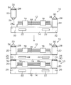
- FIG. 1 is an external perspective view of a plate-shaped packaging container according to an embodiment.
- FIG. 2 is a side view of a form in which the plate-shaped packaging containers shown in FIG. 1 are stacked one above the other.
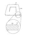
- FIG. 3 is an enlarged perspective view of the shock absorbing sheet according to the first embodiment of the buffer member attached to the column of FIG.
- FIG. 1 is an external perspective view of a plate-like packaging container 10 according to an embodiment.
- FIG. 2 is a side view showing a state immediately before two plate-like body packaging containers 10 and 10 are stacked one above the other, and a third stage plate-like body packaging container 10 is stacked on the upper plate-like body packaging container 10.
- FIG. 1 is an external perspective view of a plate-like packaging container 10 according to an embodiment.
- FIG. 2 is a side view showing a state immediately before two plate-like body packaging containers 10 and 10 are stacked one above the other, and a third stage plate-like body packaging container 10 is stacked on the upper plate-like body packaging container 10.
- FIG. 1 is an external perspective view of a plate-like packaging container 10 according to an embodiment.
- FIG. 2 is a side view showing a state immediately before two plate-like body packaging containers 10 and 10 are stacked one above the other, and a third stage plate-like body packaging container 10 is stacked on the upper plate-like body packaging container 10.
- FIG. 1 is an
- a glass plate laminated body 12 in which a plurality of (for example, 80 to 150) rectangular glass plates are horizontally laminated via sheets such as slip sheets is packed.
- the glass plate is a thin large glass plate used for FPD, for example, a large glass plate having a thickness of 0.2 mm to 2.8 mm and a vertical and horizontal size of about 2400 mm ⁇ 2100 mm to 3200 mm ⁇ 3000 mm.
- the slip sheet has a rough surface with a smoothness of 18 seconds or less (JIS P8119, 1976), for example, and the contact area with the glass plate is reduced to transfer the resin component of the slip sheet to the glass plate. Paper quality that does not cause paper texture, burns, dirt, etc.
- the resin component of the slip sheet is 0.05% by mass or less (JIS P8205, 1976), and the paper quality is selected so as not to adversely affect the quality of the glass plate itself due to the combined effect with the paper surface roughness described above. in use.
- the total mass of the plate-shaped packaging container 10 (the mass of the plate-shaped packaging container 10 alone + the mass of the glass plate laminate 12) is 2200 kg (including a total mass error of about ⁇ 5%). ) Is illustrated.
- a glass plate is illustrated as a plate-shaped body packed in the plate-shaped body packing container 10, it is not limited to a glass plate, Resin-made or metal-made plate-shaped bodies may be sufficient.
- the plate-shaped packaging container 10 mainly includes a rectangular parallelepiped pedestal 14 and a plate-shaped body mounting plate 16, horizontal pressing members 18, 18... Of the glass plate laminate 12, and prismatic columns 20, 20. .
- the support column 20 is erected in the vertical direction at the four corners of the upper surface of the pedestal 14, and when a plurality of (three in FIG. 2) plate-like packaging containers 10, 10.
- the plate-shaped packaging container 10 positioned at the lower stage is a member that supports the plate-shaped packaging container 10 positioned at the upper level. The configuration of the column 20 will be described later.
- the base 14 is configured in a frame shape by a plurality of steel materials.
- the steel material is manufactured by, for example, an extruded material made of an aluminum alloy or a steel plate cut into a predetermined shape. At least two of these steel materials assembled vertically and horizontally in the form of a lattice are manufactured, and assembled with the steel materials so that each lattice surface is substantially parallel. Thereby, the base 14 is configured.
- the component of the pedestal 14 may be made of metal or resin as long as it is rigid and does not generate particles, but aluminum or aluminum alloy is used in terms of weight, rigidity, and cost. preferable.
- fork lift openings 22 into which forks of a forklift (not shown) are inserted are provided on two sides of the pedestal 14 on one side of the pedestal 14. Thereby, the fork of the forklift can be inserted from any side surface of the base 14.
- the plate-like body mounting plate 16 is mounted on the upper surface of the pedestal 14 via a vibration absorbing member, an inclination angle setting member, and the like (not shown).
- the two horizontal holding members 18 are arranged at predetermined intervals on each of the four sides of the glass plate laminate 12, and are fixed to the plate-like body mounting plate 16 by screws (not shown). Moreover, when the horizontal pressing member 18 is fastened by the screw, the glass plate laminate 12 is pressed from the side by the horizontal pressing member 18. Thereby, the four sides of the glass plate laminate 12 are sandwiched between the lateral pressing members 18, 18.
- a rubber or resin shock absorbing sheet (buffer member) 34 is attached to a flat portion around the convex portion 30 of the upper end surface 28 of the support column 20. Since the shock absorbing sheet 34 is in close contact with the lower surface of the base 14 of the upper plate-shaped packaging container 10, vibrations transmitted from the lower plate-shaped packaging container 10 to the upper plate-shaped packaging container 10; and Impact is alleviated.
- the support column 20 is removed from the hole 24 of the base 14 when the glass plate laminate 12 is loaded and unloaded.
- FIG. 3 is an enlarged perspective view of the shock absorbing sheet 34 according to the first embodiment.
- the plate-like packaging container 10 is configured such that when the upper plate-like packaging container 10 is lifted with respect to the lower plate-like packaging container 10 by a forklift, the column 20 of the lower plate-like packaging container 10 is supported.
- the conventional problem that it is brought into close contact with the lower surface of the base 14 of the upper plate-shaped packaging container 10 and lifted together with the upper plate-shaped packaging container 10 is solved.
- the lower surface of the pedestal 14 is formed by roughening the contact surface 34A of the impact absorbing sheet 34 of the column 20 of the plate-shaped body packaging container 10 according to the embodiment (surface that is in close contact with the lower surface of the pedestal 14). The adhesive strength against is reduced.
Landscapes
- Engineering & Computer Science (AREA)
- Mechanical Engineering (AREA)
- Packaging Frangible Articles (AREA)
- Pallets (AREA)
Abstract
本発明は、上下に積み重ねられる板状体梱包容器であって、直方体形状の台座と、前記台座の上面に搭載されるとともにその上面に板状体積層体が載置される板状体載置部材と、前記台座の上面隅部にその下部が着脱自在に取り付けられるとともに、上段に位置する板状体梱包容器の台座の下面に当接する当接面を備えた緩衝部材がその上端面に設けられた支柱と、を備え、前記緩衝部材の前記当接面は、凹凸状に形成されている板状体梱包容器に関する。
Description
本発明は、板状体梱包容器に関する。
特許文献1には、板状体である液晶ディスプレイ、プラズマディスプレイ等のフラットパネルディスプレイ(FPD:FLAT Panel Display)用ガラス板を梱包する板状体梱包容器が開示されている。
この板状体梱包容器は、台座と、台座に搭載された板状体載置部材とを備えており、前記板状体載置部材にガラス板積層体が載置されて梱包される。前記ガラス板積層体とは、複数枚のガラス板が合紙等のシートを介して平置きに積層された形態である。
板状体梱包容器は、輸送車両によって輸送される際に、輸送車両の荷台に上下に積み重ねられる。このため、板状体梱包容器の台座の上面四隅には支柱が立設されている。支柱の上端面には凸部(convex)が備えられており、また、台座の下面には、前記凸部に嵌合される凹部(concave)が備えられている。したがって、下段に位置する板状体梱包容器の支柱の前記凸部に、上段に位置する板状体梱包容器の台座の前記凹部を嵌合させることによって、下段の板状体梱包容器に上段の板状体梱包容器が積み重ねられる。
また、特許文献2に開示された板状体梱包容器の支柱の上端面は、凸部とその周囲に平坦部とを有し、前記平坦部にゴム製の緩衝部材が貼り付けられている。前記緩衝部材が、上段に位置する板状体梱包容器の台座の下面に当接することによって下段の板状体梱包容器から上段の板状体梱包容器に伝達する振動、及び衝撃を緩和している。更に、特許文献2の板状体梱包容器の台座には、板状体梱包容器を荷積みしたり搬送したりするために、フォークリフトのフォークが挿入される開口部が備えられている。
前記支柱は、前記台座の上面隅部に備えられた穴部に、支柱の下部が着脱自在に嵌挿されている。支柱は、板状体梱包容器からガラス板積層体の積み降し作業を行う際に、その作業の邪魔にならないように、台座から取り外される。特許文献3の板状体梱包容器は、取り外した支柱を保管するために、支柱の収容部を台座に設けている。
ここで、ガラス板積層体が梱包された板状体梱包容器の全体質量について説明する。
一例として第8世代サイズのガラス板(奥行き寸法×横幅の寸法が2.5m×2.2m、又は2.4m×2.1m、板厚が0.2~2.8mm、約10kg/枚)が120枚積層されたガラス板積層体を板状体梱包容器に梱包した場合、その板状体梱包容器の全体質量は、1500~1600kgとなる。しかしながら、近年のFPDの大画面化によるガラス板の大型化、及び積層枚数の増加に伴って、板状体梱包容器の全体質量は2200kg程度に増大する傾向にある。
ところで最近の板状体梱包容器では、フォークリフトを使用して上段の板状体梱包容器を下段の板状体梱包容器に対して上方に持ち上げた際に、下段の板状体梱包容器の支柱が、上段の板状体梱包容器の台座の下面に密着された状態で持ち上げられ、その後、支柱が上段の板状体梱包容器から落下するという問題が発生した。
このような不具合は、支柱の下部と台座の穴部との嵌め合いを、締り嵌め又は中間嵌めで構成し、台座の穴部に対する支柱の引抜き力を前記密着の密着力よりも高めることによって解決できる。しかしながら、この対策では、支柱が穴部から抜け難くなるため、ガラス板積層体の積み降し作業効率に支障を与えるという問題があった。よって、支柱の下部と台座の穴部との嵌め合いは、隙間嵌めに設定せざるを得なかった。
本発明は、このような問題に鑑みてなされたものであり、下段に位置する板状体梱包容器の支柱と上段に位置する板状体梱包容器の台座との剥離性を向上させた板状体梱包容器を提供することを目的とする。
本発明は、前記目的を達成するために、上下に積み重ねられる板状体梱包容器であって、直方体形状の台座と、前記台座の上面に搭載されるとともにその上面に板状体積層体が載置される板状体載置部材と、前記台座の上面隅部にその下部が着脱自在に取り付けられるとともに、上段に位置する板状体梱包容器の台座の下面に当接する当接面を備えた緩衝部材がその上端面に設けられた支柱と、を備え、前記緩衝部材の前記当接面は、凹凸状に形成されている板状体梱包容器を提供する。
本発明は、以下の点に着目してなされたものである。
前述の如く、板状体梱包容器の全体質量は、従来では1500~1600kgであったが、最近の板状体梱包容器の全体質量は、1600kgを超えて2200kgに達しようとしている。従来の前記全体質量では、支柱が持ち上げられるという前記問題は発生しなかったが、質量が増大した最近の板状体梱包容器では前記問題が発生した。つまり、前記問題の発生原因は、板状体梱包容器の全体質量が増大したことに起因して、支柱の緩衝部材と台座の下面との密着力が、従来の場合と比較して増大したことにある。
よって、前記問題を解決するには、前記密着力を低下させればよい。そこで発明者は、前記密着力と因果関係のある緩衝部材の当接面の粗さ等の面性状に着目した。そして、従来の緩衝部材の当接面の算術平均粗さRaを市販の表面粗さ測定器によって測定したところ、算術平均粗さRaは0.8μmであった。
そこで本発明は、前記従来の算術平均粗さRa等の面性状に基づき、緩衝部材の当接面を凹凸状に粗くして、台座の下面に対する緩衝部材の密着力を低下させた。
したがって、本発明によれば、下段に位置する板状体梱包容器の支柱と上段に位置する板状体梱包容器の台座との密着性が低下して剥離性が向上するので、従来の前記問題を解決できる。つまり、上段の板状体梱包容器を下段の板状体梱包容器に対して上方に持ち上げた際に、下段の板状体梱包容器の支柱は、下段の板状体梱包容器の台座に残置される。
本発明の一態様は、前記緩衝部材の前記当接面に複数の突起が備えられることにより、前記当接面が凹凸状に形成されていることが好ましい。
本発明によれば、複数の突起を当接面に備えることによって、当接面を凹凸状に形成するものである。前記突起は、複数の突起が形成されたロールを、フラットな当接面に押し付ける加工方法、つまり周知のエンボス加工方法によって形成できる。
本発明の一態様は、前記緩衝部材の前記当接面の算術平均粗さRaが0.8μm超であることが好ましい。つまり、前記当接面は、高さが微小な凹凸状に形成されていることが好ましい。
本発明の一態様によれば、緩衝部材の当接面の算術平均粗さRaを、0.8μm超としたので、前記剥離性が向上する。
本発明の一態様は、前記緩衝部材は、ゴム製又は樹脂製であることが好ましい。
本発明の一態様によれば、輸送車両での輸送時に、下段の板状体梱包容器から上段の板状体梱包容器に伝達する振動、衝撃をゴム又は樹脂の緩衝作用によって緩和できる。
本発明の板状体梱包容器によれば、下段に位置する板状体梱包容器の支柱と上段に位置する板状体梱包容器の台座との密着性が低下して剥離性が向上する。よって、上段の板状体梱包容器を下段の板状体梱包容器に対して上方に持ち上げた際に、下段の板状体梱包容器の支柱は、下段の板状体梱包容器の台座に残置される。したがって、支柱は、上段の板状体梱包容器とともに持ち上げられないので、支柱が落下するという従来の問題を解決できる。
以下、図面に従って本発明に係る板状体梱包容器の好ましい実施の形態について詳説する。なお、本明細書において、“上方”とは鉛直上方を指し、“下方”とは鉛直下方を指す。
図1は、実施の形態に係る板状体梱包容器10の外観斜視図である。図2は、2台の板状体梱包容器10、10が上下に積み重ねられ、その上段の板状体梱包容器10に3段目の板状体梱包容器10が積み重ねられる直前状態を示した側面図である。
板状体梱包容器10には、複数枚(例えば80~150枚)の矩形状ガラス板が合紙等のシートを介して水平に積層されたガラス板積層体12が梱包される。ガラス板としては、FPD用に使用される薄板の大型ガラス板であり、例えば板厚は0.2mm~2.8mmであり、縦横サイズが約2400mm×2100mm~3200mm×3000mmの大型ガラス板である。また、前記合紙は、例えば平滑度18秒以下(JIS P 8119,1976)の粗面を有し、ガラス板との接触面積を小さくして合紙の樹脂成分がガラス板に転写されてガラス面に紙肌模様、焼け、汚れ等が生じないような紙質が選択されて使用されている。更に合紙の樹脂成分は、0.05質量%以下(JIS P 8205,1976)であり、上述した紙面粗さとの複合効果によってガラス板自体の品質に悪影響を及ぼさないような紙質が選択されて使用されている。
なお、実施の形態では、一例として板状体梱包容器10の全体質量(板状体梱包容器10単体の質量+ガラス板積層体12の質量)が2200kg(±5%程度の全体質量誤差を含む)の板状体梱包容器10を例示する。また、板状体梱包容器10に梱包される板状体としてガラス板を例示するが、ガラス板に限定されるものではなく、樹脂製又は金属製の板状体であってもよい。
板状体梱包容器10は、直方体形状の台座14及び板状体載置板16、ガラス板積層体12の横押さえ部材18、18…、及び角柱形状の支柱20、20…を主として構成される。支柱20は、台座14の上面四隅に鉛直方向に立設され、図2の如く複数台(図2では3台)の板状体梱包容器10、10…を上下に積み重ねて運搬する際に、下段に位置する板状体梱包容器10が上段に位置する板状体梱包容器10を支持する部材となる。支柱20の構成については後述する。
台座14は、複数本の鋼材によってフレーム状に構成される。前記鋼材は、例えばアルミニウム合金からなる押し出し材や鋼板を所定の形状に切断したものによって製造される。これらの鋼材を縦横に格子状に組み付けたものを少なくとも2基製作し、各々の格子面が略平行になるように鋼材によって組み付ける。これによって、台座14が構成される。なお、台座14の構成部材としては、剛性を備え、パーティクルが発生しない材質であれば金属製であっても樹脂製であってもよいが、重量、剛性、コストの面からアルミニウム又はアルミニウム合金が好ましい。
また、台座14の全側面には、フォークリフト(不図示)のフォークが挿入されるフォークリフト用の開口部22が台座14の一側面につき2箇所備えられている。これにより、台座14のいずれの側面からフォークリフトのフォークが挿入できる。
板状体載置板16は、不図示の振動吸収部材、及び傾斜角度設定部材等を介して台座14の上面に搭載されている。
横押さえ部材18は、ガラス板積層体12の4辺の各辺に所定の間隔をもって2個配置され、不図示のねじによって板状体載置板16に固定される。また、前記ねじによって横押さえ部材18を締結していくと、ガラス板積層体12は横押さえ部材18によって側面から押圧されていく。これにより、ガラス板積層体12の4辺が横押さえ部材18、18…によって挟持される。
台座14の上面四隅には、鉛直方向に穴部24が設けられており、各々の穴部24に支柱20の下部26が着脱自在に嵌挿される。これによって、支柱20が台座14の上面四隅に鉛直方向に立設される。支柱20の下部26の形状は、四角錐で示されているが、これに限定されない。
支柱20は、複数台の板状体梱包容器10を上下に積み重ねて輸送する際に、下段の板状体梱包容器10が上段の板状体梱包容器10を支持する役割を果たす。このため、支柱20の上端面28は、板状体載置板16の上面に載置されたガラス板積層体12の最上面よりも上方に位置される。なお、1本の支柱20の質量は約3.6kgである。
支柱20の上端面28の中央には、四角錐形状の凸部30が設けられており、この凸部30が、複数台の板状体梱包容器10、10…を上下に積み重ねる際に、上段の板状体梱包容器10の台座14の下面四隅に設けられた凹部32に嵌合される。
また、支柱20の上端面28の凸部30の周囲の平坦部には、ゴム製又は樹脂製の衝撃吸収シート(緩衝部材)34が貼り付けられる。この衝撃吸収シート34は、上段の板状体梱包容器10の台座14の下面に密着しているため、下段の板状体梱包容器10から上段の板状体梱包容器10に伝達する振動、及び衝撃が緩和される。この支柱20は、ガラス板積層体12の積み降し作業時には、台座14の穴部24から取り外される。
図3は、第1の形態に係る衝撃吸収シート34の拡大斜視図である。
実施の形態の板状体梱包容器10は、上段の板状体梱包容器10をフォークリフトによって下段の板状体梱包容器10に対して持ち上げた際に、下段の板状体梱包容器10の支柱20が、上段の板状体梱包容器10の台座14の下面に密着して、上段の板状体梱包容器10とともに持ち上げられるという、従来の問題を解決している。
次に、前記問題を解決するための手段について説明する。
すなわち、実施の形態の板状体梱包容器10の支柱20の衝撃吸収シート34の当接面(台座14の下面に密着する面)34Aを凹凸状に形成して粗くして、台座14の下面に対する密着力を低下させている。
従来の板状体梱包容器の全体質量は、1500~1600kgであったが、最近の板状体梱包容器10の全体質量は、2200kgに達しようとしている。従来の前記全体質量では、支柱20が持ち上げられるという前記問題は発生しなかったが、質量が増大した最近の板状体梱包容器10では前記問題が発生した。つまり、前記問題の発生原因は、板状体梱包容器10の全体質量が2200kgに増大したことに起因して、支柱20の衝撃吸収シート34と台座14の下面との密着力が、従来の場合と比較して増大したことにある。
よって、前記問題を解決するには、前記密着力を低下させればよい。そこで発明者は、前記密着力と因果関係のある衝撃吸収シート34の当接面の粗さ等の面性状に着目した。そして、従来の衝撃吸収シートの当接面の算術平均粗さRaを市販の表面粗さ測定器によって測定したところ、算術平均粗さRaは0.8μmであった。
そこで実施の形態は、前記従来の算術平均粗さRa等の面性状に基づき、衝撃吸収シート34の当接面を凹凸状に形成して粗くして、算術平均粗さRaが0.8μmの当接面と比較して、台座14の下面に対する密着力を低下させた。
したがって、実施の形態の板状体梱包容器10によれば、下段に位置する板状体梱包容器10の支柱20と上段に位置する板状体梱包容器10の台座14との密着性が低下して剥離性が向上するので、従来の前記問題を解決できる。つまり、上段の板状体梱包容器10を下段の板状体梱包容器10に対して上方に持ち上げた際に、下段の板状体梱包容器10の支柱20は、下段の板状体梱包容器10の台座14に残置される。
具体的には、全体質量が2200kgの板状体梱包容器10において、衝撃吸収シート34の当接面34Aを凹凸状に形成して粗くして、当接面34Aの算術平均粗さRaを、Ra=0.9μmにすることによって、全体質量が1600kgを超えて2200kg以下の板状体梱包容器10において、前記従来の問題を解決できることを実験にて確認した。また、当接面34Aの算術平均粗さRaを、Ra=16.5μmの板状体梱包容器10では、板状体梱包容器10を2段積みした形態において、800時間放置したものであっても、前記従来の問題を解決できることを実験にて確認した。よって、衝撃吸収シート34の当接面34Aを凹凸状に形成して粗くして、当接面34Aの算術平均粗さRaを、0.8μm超にすることによって前記剥離性が向上する。
すなわち、板状体梱包容器10の全体質量Wが、1600kg超である場合において、衝撃吸収シート34の当接面34Aの算術平均粗さRaを、0.8μm超とすることによって、前記剥離性が向上することを突き止めた。なお、当接面34Aの算術平均粗さの上限は特に限定されない。算術平均粗さが大きいほど、板状体梱包容器10に対する剥離性がさらに向上するためである。
当接面34Aの製造方法としては、射出成形による製造方法、及びヒートローラによる転写方法がある。前者の射出成形による製造方法は、衝撃吸収シート34を成形する金型のキャビティ空間の壁面(当接面34Aを成形する壁面)を粗面化し、溶融した熱可塑性樹脂材料を前記キャビティ空間に充填することによって、衝撃吸収シート34とともに当接面34Aを製造するものである。一方、後者のヒートローラによる転写方法は、加熱加硫型の衝撃吸収シート34に、ヒートローラの粗面化された熱加圧面を押圧することによって製造するものであり、周知のエンボス加工方法を例示できる。
エンボス加工方法によれば、当接面34Aに複数の突起を形成でき、これらの突起によって当接面34Aに凹凸が形成される。エンボス加工による突起の寸法の一例は、突起を含まない衝撃吸収シート34の厚さが1.4mmとした場合、突起の山径φ:5mm、突起のピッチ:6mm、突起の高さ:1.4mmである。なお、本仕様決定前に、突起の山径φ:5mm、突起のピッチ:12mm、突起の高さ:1.4mmのシートを準備し、2200kgの板状梱包容器を3段に積み、800時間の耐久試験を実施した。その結果、1つの突起に破断が確認された為、耐久性に劣るものと判断し、この結果を受けてピッチ6mmとしている。
次に、剥離性を比較した簡易的な比較試験について説明する。
〔試験体〕
1)図3に示した衝撃吸収シート34であって、当接面34Aの算術平均粗さRaが60μmである衝撃吸収シート34をアルミニウム製の板(以下、アルミニウムプレートという。)に各々密着させた第1の実施例の試験体を準備する。
1)図3に示した衝撃吸収シート34であって、当接面34Aの算術平均粗さRaが60μmである衝撃吸収シート34をアルミニウム製の板(以下、アルミニウムプレートという。)に各々密着させた第1の実施例の試験体を準備する。
2)衝撃吸収シート34であって、当接面34Aがエンボス加工されて複数の突起が当接面34Aに形成された衝撃吸収シート34をアルミニウムプレートに各々密着させた第2の実施例の試験体を準備する。
3)当接面の算術平均粗さRaが0.8μmの従来の衝撃吸収シートをアルミニウムプレートに密着させた比較例の試験体を準備する。
〔試験方法〕
1)加圧試験機によって試験体を所定の加圧力をもって15分加圧した後、試験体を加圧試験機から取り出し、アルミニウムプレートが上面側になるように放置して、アルミニウムプレートから衝撃吸収シートが落下するまでの時間を計測する。
1)加圧試験機によって試験体を所定の加圧力をもって15分加圧した後、試験体を加圧試験機から取り出し、アルミニウムプレートが上面側になるように放置して、アルミニウムプレートから衝撃吸収シートが落下するまでの時間を計測する。
2)加圧力は、1台の板状体梱包容器10の質量(2200kg)に相当する第1の荷重、2台の板状体梱包容器10の質量に相当する第2の荷重、3台の板状体梱包容器10の質量に相当する第3の荷重、及び4台の板状体梱包容器10の質量に相当する第4の荷重に設定する。
〔実験結果〕
1)第1の実施例の試験体、及び第2の実施例の試験体では、第1~第4の荷重であっても、衝撃吸収シート34は、アルミニウムプレートに密着されておらず、衝撃吸収シート34を下面側に向けた直後に衝撃吸収シート34がアルミニウムプレートから落下した。
1)第1の実施例の試験体、及び第2の実施例の試験体では、第1~第4の荷重であっても、衝撃吸収シート34は、アルミニウムプレートに密着されておらず、衝撃吸収シート34を下面側に向けた直後に衝撃吸収シート34がアルミニウムプレートから落下した。
2)比較例の試験体では、衝撃吸収シートがアルミニウムプレートに密着しているため、衝撃吸収シートを下方に向けても、約3分から6分程度、密着を維持し、その後、衝撃吸収シート34がアルミニウムプレートから落下した。
上記比較試験からも分かるように、実施の形態の衝撃吸収シート34は、従来の衝撃吸収シートと比較して剥離性が格段に向上したことが判明した。
以上、実施の形態の板状体梱包容器10について詳細に説明したが、本発明は上記実施の形態に限定されず、本発明の主旨を逸脱しない範囲において、種々の改良や変更をしてもよい。
本出願は、2012年9月11日出願の日本特許出願2012-199375に基づくものであり、その内容はここに参照として取り込まれる。
10…板状体梱包容器、12…ガラス板積層体、14…台座、16…板状体載置板、18…横押さえ部材、20…支柱、22…開口部、24…穴部、26…支柱の下部、28…支柱の上端面、30…凸部、32…凹部、34…衝撃吸収シート、34A…当接面
Claims (4)
- 上下に積み重ねられる板状体梱包容器であって、直方体形状の台座と、前記台座の上面に搭載されるとともにその上面に板状体積層体が載置される板状体載置部材と、前記台座の上面隅部にその下部が着脱自在に取り付けられるとともに、上段に位置する板状体梱包容器の台座の下面に当接する当接面を備えた緩衝部材がその上端面に設けられた支柱と、を備え、
前記緩衝部材の前記当接面は、凹凸状に形成されている板状体梱包容器。 - 前記緩衝部材の前記当接面に複数の突起が備えられることにより、前記当接面が凹凸状に形成されている請求項1に記載の板状体梱包容器。
- 前記緩衝部材の前記当接面の算術平均粗さRaが0.8μm超である請求項1に記載の板状体梱包容器。
- 前記緩衝部材は、ゴム製又は樹脂製である請求項1~3のいずれか1項に記載の板状体梱包容器。
Applications Claiming Priority (2)
| Application Number | Priority Date | Filing Date | Title |
|---|---|---|---|
| JP2012-199375 | 2012-09-11 | ||
| JP2012199375A JP2015214336A (ja) | 2012-09-11 | 2012-09-11 | 板状体梱包容器 |
Publications (1)
| Publication Number | Publication Date |
|---|---|
| WO2014041959A1 true WO2014041959A1 (ja) | 2014-03-20 |
Family
ID=50278084
Family Applications (1)
| Application Number | Title | Priority Date | Filing Date |
|---|---|---|---|
| PCT/JP2013/072022 Ceased WO2014041959A1 (ja) | 2012-09-11 | 2013-08-16 | 板状体梱包容器 |
Country Status (3)
| Country | Link |
|---|---|
| JP (1) | JP2015214336A (ja) |
| TW (1) | TW201418116A (ja) |
| WO (1) | WO2014041959A1 (ja) |
Families Citing this family (1)
| Publication number | Priority date | Publication date | Assignee | Title |
|---|---|---|---|---|
| JP7325713B2 (ja) * | 2019-08-16 | 2023-08-15 | 日本電気硝子株式会社 | ガラス板梱包体 |
Citations (3)
| Publication number | Priority date | Publication date | Assignee | Title |
|---|---|---|---|---|
| JPH0737928U (ja) * | 1993-12-27 | 1995-07-14 | 伊豫鉄工株式会社 | パレット・サポータ |
| JP2006199348A (ja) * | 2005-01-21 | 2006-08-03 | Isamu Sato | 食品収納容器及び該容器の製造方法 |
| WO2011086731A1 (ja) * | 2010-01-13 | 2011-07-21 | 旭硝子株式会社 | 板状体の収納容器及び収納体並びに板状体の積載装置及び運搬車両 |
-
2012
- 2012-09-11 JP JP2012199375A patent/JP2015214336A/ja active Pending
-
2013
- 2013-08-16 WO PCT/JP2013/072022 patent/WO2014041959A1/ja not_active Ceased
- 2013-08-28 TW TW102130913A patent/TW201418116A/zh unknown
Patent Citations (3)
| Publication number | Priority date | Publication date | Assignee | Title |
|---|---|---|---|---|
| JPH0737928U (ja) * | 1993-12-27 | 1995-07-14 | 伊豫鉄工株式会社 | パレット・サポータ |
| JP2006199348A (ja) * | 2005-01-21 | 2006-08-03 | Isamu Sato | 食品収納容器及び該容器の製造方法 |
| WO2011086731A1 (ja) * | 2010-01-13 | 2011-07-21 | 旭硝子株式会社 | 板状体の収納容器及び収納体並びに板状体の積載装置及び運搬車両 |
Also Published As
| Publication number | Publication date |
|---|---|
| TW201418116A (zh) | 2014-05-16 |
| JP2015214336A (ja) | 2015-12-03 |
Similar Documents
| Publication | Publication Date | Title |
|---|---|---|
| JP5382027B2 (ja) | 板状体梱包箱及び板状体搬送方法 | |
| TWI436931B (zh) | Glass plate binding body and glass plate laminated body packing method | |
| TWI343892B (ja) | ||
| JP4911276B2 (ja) | 板状体梱包箱、板状体搬送方法 | |
| JP5354280B2 (ja) | ガラス板梱包体 | |
| JP5787107B2 (ja) | ガラス板梱包体 | |
| JPWO2014162953A1 (ja) | 板状体の梱包体 | |
| KR20130140118A (ko) | 곤포 용기 및 곤포체 | |
| JP2010036948A (ja) | ガラス板梱包体 | |
| CN103313918A (zh) | 包装容器及包装体 | |
| JP2007153395A (ja) | 大型板状体梱包箱 | |
| JP2014198608A (ja) | ガラス板梱包体のアダプタ | |
| JP2015214336A (ja) | 板状体梱包容器 | |
| WO2023181973A1 (ja) | ガラス板梱包体 | |
| JP2014069850A (ja) | 板状体梱包容器 | |
| JP2010111424A (ja) | ガラス板梱包体 | |
| JP7325713B2 (ja) | ガラス板梱包体 | |
| CN102616487A (zh) | 大型板状体包装箱 | |
| CN207482465U (zh) | 大型板状体包装箱 | |
| JP5464466B2 (ja) | ガラス板梱包体 | |
| JP3233478U (ja) | 板状体梱包箱 | |
| JP7720132B2 (ja) | ガラス板梱包用パレット、ガラス板梱包体及びガラス板梱包体の製造方法 | |
| JP2011225406A (ja) | ガラス板積層体 |
Legal Events
| Date | Code | Title | Description |
|---|---|---|---|
| 121 | Ep: the epo has been informed by wipo that ep was designated in this application |
Ref document number: 13836775 Country of ref document: EP Kind code of ref document: A1 |
|
| NENP | Non-entry into the national phase |
Ref country code: DE |
|
| 122 | Ep: pct application non-entry in european phase |
Ref document number: 13836775 Country of ref document: EP Kind code of ref document: A1 |
|
| NENP | Non-entry into the national phase |
Ref country code: JP |