WO2014041891A1 - 空気調和機 - Google Patents
空気調和機 Download PDFInfo
- Publication number
- WO2014041891A1 WO2014041891A1 PCT/JP2013/069486 JP2013069486W WO2014041891A1 WO 2014041891 A1 WO2014041891 A1 WO 2014041891A1 JP 2013069486 W JP2013069486 W JP 2013069486W WO 2014041891 A1 WO2014041891 A1 WO 2014041891A1
- Authority
- WO
- WIPO (PCT)
- Prior art keywords
- guide
- shutter
- gear
- rail
- gear holder
- Prior art date
- Legal status (The legal status is an assumption and is not a legal conclusion. Google has not performed a legal analysis and makes no representation as to the accuracy of the status listed.)
- Ceased
Links
Images




Classifications
-
- F—MECHANICAL ENGINEERING; LIGHTING; HEATING; WEAPONS; BLASTING
- F24—HEATING; RANGES; VENTILATING
- F24F—AIR-CONDITIONING; AIR-HUMIDIFICATION; VENTILATION; USE OF AIR CURRENTS FOR SCREENING
- F24F13/00—Details common to, or for air-conditioning, air-humidification, ventilation or use of air currents for screening
- F24F13/08—Air-flow control members, e.g. louvres, grilles, flaps or guide plates
- F24F13/10—Air-flow control members, e.g. louvres, grilles, flaps or guide plates movable, e.g. dampers
-
- F—MECHANICAL ENGINEERING; LIGHTING; HEATING; WEAPONS; BLASTING
- F24—HEATING; RANGES; VENTILATING
- F24F—AIR-CONDITIONING; AIR-HUMIDIFICATION; VENTILATION; USE OF AIR CURRENTS FOR SCREENING
- F24F1/00—Room units for air-conditioning, e.g. separate or self-contained units or units receiving primary air from a central station
- F24F1/0007—Indoor units, e.g. fan coil units
-
- F—MECHANICAL ENGINEERING; LIGHTING; HEATING; WEAPONS; BLASTING
- F24—HEATING; RANGES; VENTILATING
- F24F—AIR-CONDITIONING; AIR-HUMIDIFICATION; VENTILATION; USE OF AIR CURRENTS FOR SCREENING
- F24F1/00—Room units for air-conditioning, e.g. separate or self-contained units or units receiving primary air from a central station
- F24F1/0007—Indoor units, e.g. fan coil units
- F24F1/0011—Indoor units, e.g. fan coil units characterised by air outlets
-
- F—MECHANICAL ENGINEERING; LIGHTING; HEATING; WEAPONS; BLASTING
- F24—HEATING; RANGES; VENTILATING
- F24F—AIR-CONDITIONING; AIR-HUMIDIFICATION; VENTILATION; USE OF AIR CURRENTS FOR SCREENING
- F24F1/00—Room units for air-conditioning, e.g. separate or self-contained units or units receiving primary air from a central station
- F24F1/0007—Indoor units, e.g. fan coil units
- F24F1/0043—Indoor units, e.g. fan coil units characterised by mounting arrangements
- F24F1/005—Indoor units, e.g. fan coil units characterised by mounting arrangements mounted on the floor; standing on the floor
-
- F—MECHANICAL ENGINEERING; LIGHTING; HEATING; WEAPONS; BLASTING
- F24—HEATING; RANGES; VENTILATING
- F24F—AIR-CONDITIONING; AIR-HUMIDIFICATION; VENTILATION; USE OF AIR CURRENTS FOR SCREENING
- F24F13/00—Details common to, or for air-conditioning, air-humidification, ventilation or use of air currents for screening
- F24F13/08—Air-flow control members, e.g. louvres, grilles, flaps or guide plates
- F24F13/10—Air-flow control members, e.g. louvres, grilles, flaps or guide plates movable, e.g. dampers
- F24F13/14—Air-flow control members, e.g. louvres, grilles, flaps or guide plates movable, e.g. dampers built up of tilting members, e.g. louvre
- F24F13/142—Air-flow control members, e.g. louvres, grilles, flaps or guide plates movable, e.g. dampers built up of tilting members, e.g. louvre using pivoting blades with intersecting axles
-
- F—MECHANICAL ENGINEERING; LIGHTING; HEATING; WEAPONS; BLASTING
- F24—HEATING; RANGES; VENTILATING
- F24F—AIR-CONDITIONING; AIR-HUMIDIFICATION; VENTILATION; USE OF AIR CURRENTS FOR SCREENING
- F24F13/00—Details common to, or for air-conditioning, air-humidification, ventilation or use of air currents for screening
- F24F13/08—Air-flow control members, e.g. louvres, grilles, flaps or guide plates
- F24F13/10—Air-flow control members, e.g. louvres, grilles, flaps or guide plates movable, e.g. dampers
- F24F13/14—Air-flow control members, e.g. louvres, grilles, flaps or guide plates movable, e.g. dampers built up of tilting members, e.g. louvre
- F24F13/1426—Air-flow control members, e.g. louvres, grilles, flaps or guide plates movable, e.g. dampers built up of tilting members, e.g. louvre characterised by actuating means
- F24F2013/1446—Air-flow control members, e.g. louvres, grilles, flaps or guide plates movable, e.g. dampers built up of tilting members, e.g. louvre characterised by actuating means with gearings
Definitions
- the present invention relates to an air conditioner in which a shutter mechanism for opening and closing the air outlet is provided at an air outlet that blows out temperature-controlled air into the room.
- a floor-standing type air conditioner normally blows out air whose temperature is adjusted by circulating a heat exchanger in the unit body from the air outlet provided in the upper front of the front panel of the unit body. It is said that.
- an air conditioner provided with a shutter mechanism that opens an air outlet when the air conditioner is operating and closes the air outlet when the operation is stopped has been put into practical use.
- the shutter mechanism is movable up and down along a pair of guide rails provided vertically on both sides of the air outlet, and includes a plate-like shutter that opens and closes the air outlet and an elevator mechanism that raises and lowers the plate shutter. It is set as the structure provided.
- the lifting mechanism includes a rack that moves up and down along a pair of left and right guide rails provided on the base side of the unit body, and is provided on the rack in the vertical direction.
- the rack gear is engaged with the gear fixed to the output shaft of the drive motor installed on the base side, and the rack is raised and lowered along the guide rail by forward and reverse rotation of the drive motor.
- the outlet is opened and closed by raising and lowering the connected shutters.
- the present invention has been made in view of such circumstances, and has a structure in which a lifting mechanism that lifts and lowers a shutter of a shutter mechanism that opens and closes an outlet is thinned so that a thickness dimension of the unit does not increase and an assembly is performed. It aims at providing the air conditioner which can improve performance and serviceability.
- the air conditioner of the present invention employs the following means. That is, the air conditioner according to the first aspect of the present invention is the air conditioner in which a shutter mechanism that opens and closes the air outlet is provided at the air outlet that blows the temperature-controlled air into the room.
- the mechanism includes a shutter that moves up and down along the air outlet, opens and closes the air outlet, and an elevating mechanism that raises and lowers the shutter, and the elevating mechanism is installed on a base on the unit body side,
- a drive motor with an output shaft protruding to the front side, a gear fixed to the output shaft, and a rack gear meshing with the gear are provided in the vertical direction, and guide pins are provided on the upper and lower sides on the left and right sides.
- Said guide pins of said gear holder guide at a position along the direction has a notch can be inserted into the rail portion, notch portion is capable restored by rail cover.
- an air conditioner provided with a shutter mechanism that includes a shutter that opens and closes an air outlet and an elevating mechanism that elevates and lowers the shutter.
- a drive motor installed on the base with the output shaft protruding to the front side, a gear fixed to the output shaft, and a rack gear that meshes with the gear are provided in the vertical direction, and guides are provided vertically on the left and right sides.
- a gear holder guide provided with a pin, and a pair of left and right guide rails that guide the gear holder guide to be movable up and down through the guide pin.
- the gear holder guide has a notch that allows the guide pin of the gear holder guide to be inserted into the rail, and the notch can be restored by the rail cover. Even after the drive motor with the output shaft protruding to the front side of the base is fixedly installed, the guide pin is inserted into the pair of left and right guide rails from the notch to protrude to the front side. Without being obstructed by the output shaft of the drive motor, the gear holder guide can be assembled to the guide rail so as to be movable up and down through the guide pins. Then, after the gear holder guide is assembled, the rail function of the guide rail can be restored by attaching a rail cover to the notch.
- the gear holder guide can be inserted into the guide rail and assembled, simplifying the assembling of the lifting mechanism and service maintenance, and improving assembling and serviceability.
- the gear holder guide, and hence the lifting mechanism can be made thin so that the thickness dimension of the unit does not increase.
- the air conditioner according to the second aspect of the present invention is the above air conditioner, wherein the notch is a position along the longitudinal direction of the guide rail, and the output shaft of the drive motor projects. It is provided in an upper part than the position to do.
- the drive motor Insert the upper guide pin in the guide pins provided on the top and bottom of the left and right sides of the gear holder guide into the notch at a position above the position where the output shaft protrudes, and incorporate the gear holder guide.
- the gear holder guide can be assembled between the pair of guide rails in a state where the output shaft of the drive motor protrudes into the vertical space along the rack gear provided in the gear holder guide.
- the assembly work can be simplified and simplified, and the number of man-hours can be greatly reduced, compared to the case where the drive motor is installed on the back side. it can.
- what is necessary is just to insert the lower guide pin of a gear holder guide into a rail part from the lower end part of a guide rail.
- the air conditioner according to the third aspect of the present invention is the air conditioner according to any one of the above-described air conditioners, wherein the rail cover is detachable and is installed in the notch portion, whereby the rail of the guide rail is provided. The function can be restored.
- the rail cover since the rail cover is detachable and is configured to be able to restore the rail function of the guide rail by being installed in the notch, the rail cover is removed. Open the notch in the state and insert the upper guide pin on the gear holder guide side into the rail part of the pair of left and right guide rails, so that the gear is not obstructed by the output shaft of the drive motor protruding to the front side.
- the holder guide can be incorporated into the guide rail, the rail function of the guide rail can be restored to its original state by installing the rail cover after installing the gear holder guide, and the gear holder guide can be smoothly moved along the guide rail.
- a sliding guide can be provided. Therefore, the drive motor, the guide rail, and the gear holder guide can be sequentially assembled by attaching and detaching the rail cover, and the lifting mechanism can be easily disassembled and assembled even during maintenance.
- an air conditioner according to a fourth aspect of the present invention is the air conditioner according to any one of the above-described air conditioners, wherein the gear holder guide is a vertically long rectangular frame, and the rack gear is disposed at a substantially central portion in the frame. Are integrally provided along the length direction.
- the gear holder guide is a vertically long rectangular frame, and a rack gear is integrally provided along the length direction at a substantially central portion in the frame. Therefore, the gear holder guide itself holding the rack gear can be reduced in weight by using a frame structure and reducing the amount of constituent materials used. Accordingly, the material cost can be reduced and the cost can be reduced, and the drive motor that raises and lowers the gear holder guide can be reduced in size and the power consumption can be reduced.
- the air conditioner of the fifth aspect of the present invention is the above air conditioner, wherein the gear holder guide is integrally provided with a plurality of horizontal lattices between one vertical frame and the rack gear. ing.
- a plurality of horizontal lattices are integrally provided between one vertical frame of the gear holder guide and the rack gear.
- an air conditioner according to a sixth aspect of the present invention is the air conditioner according to any one of the above-described air conditioners, wherein the shutter and the elevating mechanism include a lower end portion of the shutter and an upper end of the gear holder guide of the elevating mechanism.
- the parts are connected to each other via a connector that is rotatably coupled by a shaft.
- the shutter and the elevating mechanism are coupled via the connector in which the lower end portion of the shutter and the upper end portion of the gear holder guide of the elevating mechanism are coupled to each other by a shaft. Therefore, by moving the gear holder guide of the elevating mechanism up and down in the vertical direction, the shutter connected to the upper end portion via the connector has a degree of freedom in movement, and the vertical direction along the outlet It can be moved forward to the front side while moving up and down. Therefore, the shutter that opens and closes the air outlet can be easily moved to the position when the air outlet is closed and the accommodation position when the air outlet is opened.
- the guide pins are inserted into the pair of left and right guide rails from the notch portions even after the drive motor having the output shaft protruding to the front side is fixedly installed on the base of the main body side.
- the gear holder guide can be assembled to the guide rail so as to be movable up and down via the guide pin without being obstructed by the output shaft of the drive motor protruding to the front side.
- the rail function of the guide rail can be restored by attaching the rail cover to the notch, so after assembling the drive motor, insert the gear holder guide into the guide rail and assemble it. It is possible to simplify the work during assembling of the lifting mechanism and service maintenance, improve the assembling property and serviceability, and reduce the thickness of the unit by reducing the thickness of the gear holder guide and eventually the lifting mechanism. Can be prevented from growing.
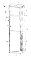
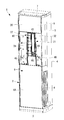
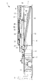
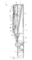
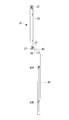
- FIG. 1 is an external perspective view of an air conditioner according to an embodiment of the present invention. It is a perspective view of the state which removed the upper front panel of the air conditioner shown in FIG. It is a longitudinal cross-sectional view of a state in which the lower front panel of the air conditioner shown in FIG. 1 is removed and a shutter that opens and closes the air outlet is lowered and accommodated on the back side of the upper front panel. It is a longitudinal cross-sectional view of the state which raised the shutter shown in FIG. 3 to the upper end vicinity of a blower outlet. It is a longitudinal cross-sectional view of the state which raised the shutter shown in FIG. 4 further, and was extruded to the front side. It is the perspective view of the state which looked at the said shutter from the front side.
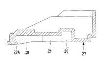
- FIG. 10 is a cross-sectional view corresponding to aa in FIG. 9.
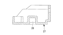
- FIG. 10 is a cross-sectional view corresponding to bb in FIG. 9. It is a perspective view of the assembly
- FIG. 14 is a perspective view of a state after the lower side of the rack holder guide shown in FIG. 13 is assembled to the guide rail.
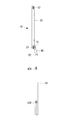
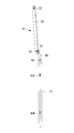
- FIG. 4 is a side view of the shutter mechanism in which the shutter and the lifting mechanism are coupled by a connector in the state of FIG. 3. It is a side view in the state of FIG. 4 of the shutter mechanism shown in FIG. It is a side view in the state of FIG. 5 of the shutter mechanism shown in FIG.
- FIG. 1 is an external perspective view of a floor-standing air conditioner according to an embodiment of the present invention
- FIG. 2 is a perspective view of a state in which the upper front panel is removed
- FIG. A longitudinal sectional view of the state in which the lower front panel is removed and a shutter for opening and closing the air outlet is housed in a lowered manner on the back side of the upper front panel is shown.
- the floor-standing air conditioner 1 includes a unit body 2 having a vertically long rectangular parallelepiped shape assembled from a rear panel 4, a left / right side panel 5, a front panel 6, a ceiling panel 7, and the like installed on a base plate 3. Yes.
- the front panel 6 is a U-shaped cross-sectional panel having rearward extensions on both sides, and is divided into two vertically, and suction grills for sucking room air into both sides of the lower front panel 6A. 8 is provided, and an air outlet 9 for blowing out temperature-adjusted air into the room is provided in front of the upper portion of the upper front panel 6B.
- the air outlet 9 is provided with a shutter mechanism 10 that opens and closes the air outlet 9.
- the shutter mechanism 10 is configured as described later, and closes the air outlet 9 when the operation of the air conditioner 1 is stopped, and opens the air outlet 9 when the air conditioner 1 is operated.
- the room air sucked from the suction grill 8 through the air filter is pumped toward the upper side of the unit main body 2 on the back side of the lower front panel 6 ⁇ / b> A, that is, inside the unit main body 2.
- a blower 11 such as a sirocco fan is incorporated.
- the blower outlet 12 of the blower 11 is connected to an air passage 13 formed in the unit body 2 in the vertical direction.
- a rectangular plate fin tube type heat exchanger 14 that is long in the vertical direction is obliquely disposed with the lower end portion positioned on the front side and the upper end portion positioned on the rear side.
- the heat exchanger 14 circulates air that is pumped from the lower side to the upper side of the air passage 13 in the vertical direction by the blower 11 and cools or heats the air by exchanging heat with the refrigerant therebetween, so that the conditioned air at a set temperature. As a result, the air is blown out from the air outlet 9 into the room.
- the heat exchanger 14 is connected to the outdoor unit side via a refrigerant pipe composed of a refrigerant gas pipe and a refrigerant liquid pipe, and constitutes a known refrigeration cycle.
- a drain pan 15 is disposed below the lower end of the heat exchanger 14, collects drain water that condenses and flows down on the surface of the heat exchanger 14, and discharges it outside through the drain pipe. Has been.
- the conditioned air temperature-controlled by the heat exchanger 14 is converted into a flow in a direction perpendicular to the air outlet 9 provided on the upper front surface of the upper front panel 6B and blown into the room.
- a plurality of vertical louvers 16 in the vertical direction and a plurality of horizontal louvers 17 in the horizontal direction are rotatably disposed at the outlet 9.
- a guide vane 18 for leading to 9 is fixedly installed on a side plate of the heat exchanger 14 via a bracket portion 19.
- the shutter mechanism 10 that opens and closes the air outlet 9 includes a shutter 20 that is installed in the air outlet 9 so as to be movable up and down along a vertical direction via a guide, and an elevating mechanism 21 that raises and lowers the shutter 20.
- the shutter 20 is a horizontally-long rectangular resin plate having substantially the same size as the air outlet 9, and the upper guide pins 22 and the lower guides made of resin are provided at the upper and lower positions of both end surfaces. Pins 23 are provided.
- the upper guide pin 22 and the lower guide pin 23 slide in a guide groove 28 of a guide rail 27 described later, and are configured to have different projecting lengths from both end faces.
- the upper guide pin 22 and the lower guide pin 23 protrude vertically from a rectangular attachment portion 25 in which a through hole of the screw 24 is provided and from one side of the attachment portion 25.
- the guide pin has the same configuration and the cylindrical pin 26 having a predetermined length.
- the upper guide pin 22 is mounted from the end surface of the shutter 20 by installing the mounting portion 25 at a position where the cylindrical pin 26 of the guide pin protrudes fully from the end surface of the shutter 20.
- the lower guide pin 23 is formed in a cylindrical shape by installing the mounting portion 25 at a position inside the predetermined dimension from the end face of the shutter 20.
- the protruding length of the pin 26 from the end face of the shutter 20 is shorter than the upper guide pin 22 by a predetermined dimension.
- the shutter 20 is movable up and down along a pair of left and right resin guide rails 27 installed on the inner surfaces of both sides of the air outlet 9 in the vertical direction.
- the guide rail 27 has a slightly wider upper portion, and extends on the inner surface side in the vertical direction in which the upper guide pin 22 and the lower guide pin 23 slide.
- a guide groove 28 having a constant depth is provided.
- the upper portion 28A of the guide groove 28 is inclined obliquely from the predetermined upper position toward the front surface side, and when the air outlet 9 is closed by the shutter 20, the upper front surface of the shutter 20 is placed on the upper front panel 6B. It is set as the structure which can be advanced to the position which becomes substantially flush with the front surface.
- Extrusion grooves 29 for extruding the lower part of the front side to the front side are provided in the horizontal direction in conjunction with the guide grooves 28. As shown in FIG. 10, only the lower guide pin 23 in which the groove depth is shallower than the guide groove 28 and the protruding length from the left and right end faces of the shutter 20 is shortened. The upper guide pin 22 is not allowed to enter the push groove 29.
- the position of the front end portion 29A protruding to the front side of the push groove 29 is the same as the position of the upper end of the upper portion 28A inclined to the front side of the guide groove 28 to the front side.
- the pin 22 and the lower guide pin 23 are moved in the guide groove 28 and the push groove 29 to a position where the air outlet 9 is closed, the front surface thereof and the front surface of the upper front panel 6B are substantially flush with each other.
- the upper portion of the guide rail 27 that is a little wider, the gap on the surface side of the guide rail is gradually narrower toward both sides of the shutter 20 toward the front side. It is set as the inclined surface 30 of the direction which becomes.
- the shutter 20 is moved up and down along the guide rail 27, the upper guide pin 22 is raised to the upper end position in the guide groove 28, and the lower guide pin 23 is pushed out to the distal end portion 29 ⁇ / b> A of the pushing groove 29.
- the air outlet 9 is closed, and in the closed position, the front surface of the shutter 20 is substantially flush with the front surface of the upper front panel 6B.
- the guide groove 28 is lowered to the lower end position, thereby forming between the back side of the upper front panel 6B and the base 31 installed in the unit main body 2 as shown in FIG. It is accommodated in the accommodating space 32.
- the elevating mechanism 21 that elevates the shutter 20 includes a pair of left and right guide rails 40 installed in parallel in the vertical direction at a predetermined interval with respect to the base 31.
- a gear holder guide 41 slidably incorporated in the vertical direction with respect to the guide rail 40 via a guide pin 42; a rack gear 43 having a predetermined length provided integrally with the gear holder guide 41 in the vertical direction;
- a drive motor 44 that is fixedly installed on the base 31 and moves up and down the gear holder guide 41 along the guide rail 40, and a gear 46 that is fixed to the output shaft 45 of the motor 44 and meshed with the rack gear 43 (see FIG. 2). ).
- the guide rail 40 is a resin rail in which rail portions (not shown) such as rail grooves along the length direction are integrally formed, and is fixedly installed on the base 31 through screws or the like.
- the gear holder guide 41 is a vertically long rectangular frame body, and a rack gear 43 is integrally molded through a plurality of reinforcing horizontal lattices 41A along the length direction at a substantially central portion in the frame body. It is.
- the guide pins 42A and 42B are integrally molded products made of a resin material, and a total of four guide pins 42A and 42B are provided on the left and right side surfaces of the gear holder guide 41 in the longitudinal direction. It is supposed to be movable.
- the guide pins 42A and 42B may have the same configuration as the upper and lower guide pins 22 and 23 described above.
- the elevating mechanism 21 is integrated with the rack gear 43 by rotating the gear 46 by rotating the drive motor 44 forward and backward, and moving the rack gear 43 meshing with the gear 46 in the vertical direction.
- the gear holder guide 41 is configured to be moved up and down along the guide rail 40 via the upper guide pin 42A and the lower guide pin 42B.
- the drive motor 44 is fixed to the base 31 with screws from the back side, and is installed so that the output shaft 45 protrudes to the front side. Since the elevating mechanism 21 has a structure in which a guide rail 40 is installed on the surface side of the drive motor 44 and a gear holder guide 41 is slidably incorporated, after the drive motor 44 is fixedly installed, the gear holder guide If it is going to assemble 41 to the guide rail 40, the output shaft 45 will become obstructive. However, if the drive motor 44 is to be installed after the guide rail 40 is inserted into the guide rail 40, it is necessary to assemble the lift mechanism 21 while being turned over several times, and the assemblability deteriorates.
- a notch portion 47 in which a part of the guide rail 40 is notched is provided at a position above the output shaft 45 of the drive motor 44 of the pair of left and right guide rails 40.
- the elevating mechanism 21 that elevates and lowers the shutter 20 is configured such that the gear holder guide 41 can be vertically moved along the guide rail 40 by a predetermined stroke when the drive motor 44 rotates forward and backward.
- one end of a connector 49 is rotatably coupled to the elevating mechanism 21 via the shaft 50 to the upper end portion of the gear holder guide 41. Is pivotally connected to the lower end of the shutter 20 via a shaft 51. For this reason, the shutter 20 is configured to be lifted and lowered via the connector 49 by the lifting and lowering of the lifting mechanism 21.
- FIG. 15 shows the postures of the shutter 20 and the elevating mechanism 21 in the guide rails 27 and 40 at this time.
- FIG. 16 shows the posture of the shutter 20 and the lifting mechanism 21 in the guide rails 27 and 40 at this time, and the upper part of the shutter 20 is inclined to the front side.
- FIG. 17 shows the postures of the shutter 20 and the lifting mechanism 21 in the guide rails 27 and 40 at this time, and the shutter 20 and the gear holder guide 41 are in parallel with each other in the vertical direction. .
- a shutter mechanism 10 that opens the air outlet 9 for blowing the conditioned air into the room during operation of the air conditioner 1 and closes the air outlet when the air conditioner 1 is stopped includes a plate-like shutter 20 that can open and close the air outlet 9, and the shutter 20 as a guide rail.
- the air outlet 9 can be opened and closed by moving the plate-like shutter 20 up and down through 23.
- the shutter 20 is housed in the housing space 32 formed on the back side of the upper front panel 6B when the air conditioner 1 is in operation.
- the shutter 20 is driven via the elevating mechanism 21. Is rotated along the guide rail 27, and the upper guide pin 22 is inclined at the upper end position of the upper portion 28A inclined forward of the guide groove 28 at the raised end position, and the lower guide pin 23 is moved to the tip end portion 29A of the push groove 29.
- the air outlet 9 is closed in a state of being substantially flush with the front surface of the upper front panel 6B.
- the raising / lowering mechanism 21 for raising and lowering the shutter 20 is fixedly installed on the base 31 on the main body side from the back side, and the output shaft 45 projects from the front side, and is fixed to the output shaft 45.
- Gear holder 46 and a rack gear 43 that meshes with the gear 46 are provided in the vertical direction, and a gear holder in the form of a vertically long rectangular frame provided with upper and lower guide pins 42A and 42B on the upper and lower sides on the left and right sides.
- a guide 41 and a pair of left and right guide rails 40 that guide the gear holder guide 41 up and down through the guide pins 42A and 42B are provided.
- the guide rails 40 are located at positions along the longitudinal direction.
- the upper guide pin 42 ⁇ / b> A of the gear holder guide 41 has a notch portion 47 into which the rail portion can be inserted. In being and restore configurable.
- the upper guide pin extends from the notch 47 to the pair of left and right guide rails 40.
- 42A is inserted into the guide rail 40 so that the gear holder guide 41, which is a vertically long rectangular frame, is not obstructed by the output shaft 45 of the drive motor 44 protruding to the front side.
- 42B can be assembled so as to be vertically movable.
- the lower guide pin 42B may be inserted into the rail portion from the lower end portion of the guide rail 40.
- the rail function of the guide rail 40 can be restored by attaching the rail cover 48 to the notch 47 after the gear holder guide 41 is assembled.
- the gear holder guide 41 can be inserted into the guide rail 40 and assembled, simplifying the work of assembling the lift mechanism 21 and service maintenance, Assemblability and serviceability can be improved, and the thickness of the unit body 2 can be prevented from being increased by reducing the thickness in the thickness direction of the gear holder guide 41 and thus the elevating mechanism 21 by reducing the thickness. .
- the notch 47 is provided at a position along the longitudinal direction of the guide rail 40 and above the position where the output shaft 45 of the drive motor 44 protrudes.
- the upper guide pins 42A of the guide pins 42A and 42B provided on the upper and lower sides of the gear holder guide 41 are inserted into the notch 47 at a position above the position where the 45 protrudes, and the gear holder
- the gear holder guide 41 is placed between the pair of guide rails 40 in a state where the output shaft 45 of the drive motor 44 protrudes into the vertical space along the rack gear 43 provided in the gear holder guide 41. Can be incorporated.
- the assembling work is simplified and simplified as compared with the case where the drive motor 44 is installed on the back side thereof, and the man-hour is greatly increased. Can be reduced.
- the lower guide pin of the gear holder guide 41 may be inserted into the rail portion from the lower end portion of the guide rail 40 as described above, and the cutout portions 47 need not be provided at a plurality of locations.
- the rail cover 48 is detachable with screws or the like, and is configured to be able to restore the rail function of the guide rail 40 by being installed in the notch 47, and with the rail cover 48 removed.
- the output shaft 45 of the drive motor 44 protruding to the front side is obstructed.
- the gear holder guide 41 can be incorporated into the guide rail 40 without any change.
- the rail cover 48 is attached and installed to restore the rail function of the guide rail 40 to the original state.
- the guide 41 can be slidably guided along the guide rail 40. Therefore, the drive motor 44, the guide rail 40, and the gear holder guide 41 can be sequentially assembled by attaching and detaching the rail cover 48, and the lifting mechanism 21 can be easily disassembled and assembled even during maintenance.
- the gear holder guide 41 is a vertically long rectangular frame, and the rack gear 43 is integrally provided along the length direction at a substantially central portion in the frame.
- the gear holder guide 41 itself can be reduced in weight by making the gear holder guide 41 to hold
- the gear holder guide 41 is configured such that a plurality of reinforcing horizontal lattices 41A are integrally formed between one vertical frame and the rack gear 43. For this reason, even if the gear holder guide 41 has a frame structure, the flexural strength can be sufficiently ensured by reinforcing the rack gear 43 that is long in the vertical direction with a plurality of horizontal lattices 41A. Accordingly, the meshing between the rack gear 43 and the gear 46 can be maintained normally, and the gear holder guide 41 can be smoothly moved up and down along the guide rail 40 by the rotation of the drive motor 44.
- the shutter 20 and the lifting mechanism 21 are connected via a connector 49 in which the lower end portion of the shutter 20 and the upper end portion of the gear holder guide 41 of the lifting mechanism 21 are coupled to each other so as to be rotatable.
- the configuration is as follows. For this reason, by raising and lowering the gear holder guide 41 of the elevating mechanism 21 in the vertical direction, the shutter 20 connected to the upper end portion thereof via the connector 49 is given a degree of freedom in movement, and the air outlet 9 It is possible to move forward along the front side while moving up and down along. Therefore, the shutter 20 that opens and closes the air outlet 9 can be easily moved to the position when the air outlet 9 is closed and the accommodation position when the air outlet 9 is opened.
- the upper guide pin 22 and the lower guide pin 23 are guide pins having the same configuration and shared, but an example in which the pin length is different may be used.
- the upper guide pin 22 and the lower guide pin 23 and the upper and lower guide pins 42A and 42B provided on the gear holder guide 41 of the elevating mechanism 21 may be configured in common.
- the gear holder guide 41 and the rack gear 43 are integrally molded products by resin, it does not necessarily need to be an integrally molded product, and it shape
- the gear holder guide 41 is a frame, a part of the plate material may be punched into a rectangular shape, and a rack gear 43 may be provided on the end face of the punched portion.
Landscapes
- Engineering & Computer Science (AREA)
- Chemical & Material Sciences (AREA)
- Combustion & Propulsion (AREA)
- Mechanical Engineering (AREA)
- General Engineering & Computer Science (AREA)
- Air-Flow Control Members (AREA)
- Air Filters, Heat-Exchange Apparatuses, And Housings Of Air-Conditioning Units (AREA)
Description
本発明は、温調された空気を室内に吹出す吹出口に、該吹出口を開閉するためのシャッター機構が設けられている空気調和機に関するものである。
床置き型の空気調和機は、通常、ユニット本体の前面パネルの上部前面に設けられた吹出口から、ユニット本体内で熱交換器を流通することにより温度調整された空気を室内に吹出す構成とされている。このような床置き型空気調和機において、空気調和機の運転時に吹出口を開口し、運転停止時に吹出口を閉鎖するシャッター機構を設けたものが実用化されている。このシャッター機構は、吹出口の両側に上下方向に設けられた一対のガイドレールに沿って昇降自在とされ、吹出口を開閉する板状のシャッターと、その板状シャッターを昇降する昇降機構とを備えた構成とされている。
昇降機構は、例えば、特許文献1に示されるように、ユニット本体のベース側に設けられている左右一対のガイドレールに沿って上下方向に昇降するラックを備え、このラックに上下方向に設けられているラックギアをベース側に設置されている駆動モータの出力軸に固定されているギアに噛み合わせた構成となし、駆動モータの正逆回転によりラックをガイドレールに沿って昇降させ、その上端に連結されているシャッターを昇降することによって、吹出口を開閉する構成とされている。
しかしながら、上記昇降機構を組み立てる際、ベースに駆動モータを固定設置し、その前面側から左右一対のガイドレールのレール部にガイドピンを挿入しながらラックを組み込もうとすると、駆動モータから突出している出力軸と干渉し、出力軸がラックの組み込み時の邪魔となる。このため、特許文献1に示すように、ラックを駆動モータおよび出力軸を跨ぐように、コの字断面形状の構成として厚さ方向寸法を大きくし、駆動モータの出力軸と干渉しないようにするか、もしくはラックを組み付け後に駆動モータを組み立てる必要があった。
しかるに、前者の構成とした場合、シャッター機構を組み込むためのスペース、すなわち厚さ方向寸法の大きいラックを組み込むためのスペースを確保しなければならず、ユニットの厚さ寸法が大きくなる等の問題があり、好ましくなかった。
また、後者のように、駆動モータを後付けしようとすると、昇降機構全体を何度もひっくり返しながら組み立てる必要があり、組み立て性が著しく低下するとともに、メンテナンス時に分解組み立てする場合の作業性も大幅に悪化する等の課題があった。
また、後者のように、駆動モータを後付けしようとすると、昇降機構全体を何度もひっくり返しながら組み立てる必要があり、組み立て性が著しく低下するとともに、メンテナンス時に分解組み立てする場合の作業性も大幅に悪化する等の課題があった。
本発明は、このような事情に鑑みてなされたものであって、吹出口を開閉するシャッター機構のシャッターを昇降する昇降機構を薄型化し、ユニットの厚さ寸法が大きくならないようにするとともに、組み立て性、サービス性を向上することができる空気調和機を提供することを目的とする。
上記した課題を解決するために、本発明の空気調和機は、以下の手段を採用する。
すなわち、本発明の第1の態様にかかる空気調和機は、温調された空気を室内に吹出す吹出口に、該吹出口を開閉するシャッター機構が設けられている空気調和機において、前記シャッター機構は、前記吹出口に沿って上下方向に昇降し、該吹出口を開閉するシャッターと、該シャッターを昇降する昇降機構とを有し、前記昇降機構は、ユニット本体側のベースに設置され、出力軸が前面側に突出されている駆動モータと、前記出力軸に固定されたギアと、該ギアと噛み合うラックギアが上下方向に設けられているとともに、左右両側の上下にガイドピンが設けられているギアホルダガイドと、該ギアホルダガイドをそのガイドピンを介して上下方向に昇降自在にガイドする左右一対のガイドレールとを備え、前記ガイドレールは、その長手方向に沿う位置に前記ギアホルダガイドの前記ガイドピンをレール部に挿入可能な切欠き部を有し、該切欠き部はレールカバーにより復元可能とされている。
すなわち、本発明の第1の態様にかかる空気調和機は、温調された空気を室内に吹出す吹出口に、該吹出口を開閉するシャッター機構が設けられている空気調和機において、前記シャッター機構は、前記吹出口に沿って上下方向に昇降し、該吹出口を開閉するシャッターと、該シャッターを昇降する昇降機構とを有し、前記昇降機構は、ユニット本体側のベースに設置され、出力軸が前面側に突出されている駆動モータと、前記出力軸に固定されたギアと、該ギアと噛み合うラックギアが上下方向に設けられているとともに、左右両側の上下にガイドピンが設けられているギアホルダガイドと、該ギアホルダガイドをそのガイドピンを介して上下方向に昇降自在にガイドする左右一対のガイドレールとを備え、前記ガイドレールは、その長手方向に沿う位置に前記ギアホルダガイドの前記ガイドピンをレール部に挿入可能な切欠き部を有し、該切欠き部はレールカバーにより復元可能とされている。
本発明の第1の態様によれば、吹出口を開閉するシャッターと、該シャッターを昇降する昇降機構とを有するシャッター機構が設けられている空気調和機にあって、昇降機構は、本体側のベースに設置され、出力軸が前面側に突出されている駆動モータと、その出力軸に固定されたギアと、該ギアと噛み合うラックギアが上下方向に設けられているとともに、左右両側の上下にガイドピンが設けられているギアホルダガイドと、該ギアホルダガイドをそのガイドピンを介して上下方向に昇降自在にガイドする左右一対のガイドレールとを備えており、このガイドレールは、その長手方向に沿う位置にギアホルダガイドのガイドピンをレール部に挿入可能な切欠き部を有し、該切欠き部はレールカバーにより復元可能とされているため、本体側のベースに出力軸が前面側に突出されている駆動モータを固定設置後であっても、左右一対のガイドレールに対してその切欠き部からガイドピンを挿入することによって、前面側に突出している駆動モータの出力軸に邪魔されることなく、ギアホルダガイドをガイドレールに対しガイドピンを介して上下方向に昇降自在に組み付けることができる。そして、ギアホルダガイドを組み付け後、切欠き部にレールカバーを取り付けることにより、ガイドレールのレール機能を復元することができる。従って、駆動モータを組み立て後に、ギアホルダガイドをガイドレールに挿入して組み付けすることが可能となり、昇降機構の組み立て時およびサービスメンテナンス時の作業を簡素化し、組み立て性およびサービス性を向上することができるとともに、ギアホルダガイド、ひいては昇降機構を薄型化し、ユニットの厚さ寸法が大きくならないようにすることができる。
さらに、本発明の第2の態様の空気調和機は、上記の空気調和機において、前記切欠き部は、前記ガイドレールの長手方向に沿う位置であって、前記駆動モータの前記出力軸が突出する位置よりも上方部位に設けられている。
本発明の第2の態様によれば、切欠き部が、ガイドレールの長手方向に沿う位置であって、駆動モータの出力軸が突出する位置よりも上方部位に設けられているため、駆動モータの出力軸が突出する位置よりも上方位置で切欠き部に対して、ギアホルダガイドの左右両側の上下に設けられているガイドピンの中の上部ガイドピンを挿入し、ギアホルダガイドを組み込むことにより、ギアホルダガイドに設けられているラックギアに沿う上下方向の空間に駆動モータの出力軸を突出させた状態で、ギアホルダガイドを一対のガイドレール間に組み込むことができる。従って、ギアホルダガイドをベース上の左右一対のガイドレール間に組み付け後、駆動モータをその背面側に設置する場合に比べ、組み立て作業を単純化、簡素化し、その工数を大幅に削減することができる。なお、ギアホルダガイドの下部ガイドピンは、ガイドレールの下端部からレール部に挿入すればよい。
さらに、本発明の第3の態様の空気調和機は、上述のいずれかの空気調和機において、前記レールカバーは、着脱自在であって前記切欠き部に設置されることにより前記ガイドレールのレール機能を復元可能な構成とされている。
本発明の第3の態様によれば、レールカバーは、着脱自在であって切欠き部に設置されることによりガイドレールのレール機能を復元可能な構成とされているため、レールカバーを取り外した状態で切欠き部を開放し、ギアホルダガイド側の上部ガイドピンを左右一対のガイドレールのレール部に挿入することにより、前面側に突出する駆動モータの出力軸に邪魔されることなく、ギアホルダガイドをガイドレールに組み込むことができる一方、ギアホルダガイドを組み付け後、レールカバーを取り付け設置することにより、ガイドレールのレール機能を元通り復元し、ギアホルダガイドをガイドレールに沿って円滑に摺動ガイドすることができる。従って、レールカバーの着脱によって駆動モータ、ガイドレール、ギアホルダガイドを順次組み立てることができ、メンテナンス時の際においても、簡便に昇降機構を分解、組み立てすることができる。
本発明の第3の態様によれば、レールカバーは、着脱自在であって切欠き部に設置されることによりガイドレールのレール機能を復元可能な構成とされているため、レールカバーを取り外した状態で切欠き部を開放し、ギアホルダガイド側の上部ガイドピンを左右一対のガイドレールのレール部に挿入することにより、前面側に突出する駆動モータの出力軸に邪魔されることなく、ギアホルダガイドをガイドレールに組み込むことができる一方、ギアホルダガイドを組み付け後、レールカバーを取り付け設置することにより、ガイドレールのレール機能を元通り復元し、ギアホルダガイドをガイドレールに沿って円滑に摺動ガイドすることができる。従って、レールカバーの着脱によって駆動モータ、ガイドレール、ギアホルダガイドを順次組み立てることができ、メンテナンス時の際においても、簡便に昇降機構を分解、組み立てすることができる。
さらに、本発明の第4の態様の空気調和機は、上述のいずれかの空気調和機において、前記ギアホルダガイドは、縦長長方形状の枠体とされ、その枠体内の略中央部位に前記ラックギアが長さ方向に沿って一体に設けられた構成とされている。
本発明の第4の態様によれば、ギアホルダガイドが、縦長長方形状の枠体とされ、その枠体内の略中央部位にラックギアが長さ方向に沿って一体に設けられた構成とされているため、ラックギアを保持するギアホルダガイドを枠体構造とし、構成材料の使用量を削減することによって、ギアホルダガイド自体を軽量化することができる。従って、材料費を低減しコストダウンすることができるとともに、軽量化によってギアホルダガイドを昇降する駆動モータを小型化し、その消費動力を節減することができる。
さらに、本発明の第5の態様の空気調和機は、上記の空気調和機において、前記ギアホルダガイドには、一方の縦枠と前記ラックギアとの間に複数本の横格子が一体に設けられている。
本発明の第5の態様によれば、ギアホルダガイドの一方の縦枠とラックギアとの間に複数本の横格子が一体に設けられているため、ギアホルダガイドを枠体構造としても、上下方向に長いラックギアを複数本の横格子で補強することにより、その撓み強度を十分確保することができる。従って、ラックギアとギアとの噛み合いを正常に維持し、ギアホルダガイドを駆動モータの回転によりガイドレールに沿って上下方向に滑らかに昇降させることができる。
さらに、本発明の第6の態様の空気調和機は、上述のいずれかの空気調和機において、前記シャッターと前記昇降機構とは、該シャッターの下端部および前記昇降機構の前記ギアホルダガイドの上端部がそれぞれ軸で回動自在に結合されたコネクタを介して連結されている。
本発明の第6の態様によれば、シャッターと昇降機構とが、該シャッターの下端部および昇降機構のギアホルダガイドの上端部がそれぞれ軸で回動自在に結合されたコネクタを介して連結されているため、昇降機構のギアホルダガイドを上下方向に昇降することにより、その上端部にコネクタを介して連結されているシャッターを、その動きに自由度を持たせ、吹出口に沿って上下方向に昇降させながら前面側に前進移動させることができる。従って、吹出口を開閉するシャッターを、吹出口を閉鎖する時の位置と、吹出口を開口する時の収容位置とに容易に移動させることが可能となる。
本発明によると、本体側のベースに出力軸が前面側に突出されている駆動モータを固定設置後であっても、左右一対のガイドレールに対してその切欠き部からガイドピンを挿入することによって、前面側に突出している駆動モータの出力軸に邪魔されることなく、ギアホルダガイドをガイドレールに対しガイドピンを介して上下方向に昇降自在に組み付けることができる。そして、ギアホルダガイドを組み付け後、切欠き部にレールカバーを取り付けることにより、ガイドレールのレール機能を復元することができるため、駆動モータを組み立て後に、ギアホルダガイドをガイドレールに挿入して組み付けすることが可能となり、昇降機構の組み立て時およびサービスメンテナンス時の作業を簡素化し、組み立て性およびサービス性を向上することができるとともに、ギアホルダガイド、ひいては昇降機構を薄型化し、ユニットの厚さ寸法が大きくならないようにすることができる。
以下に、本発明の一実施形態について、図1ないし図17を参照して説明する。
図1には、本発明の一実施形態に係る床置き型の空気調和機の外観斜視図が示され、図2には、その上部前面パネルを取外した状態の斜視図、図3には、その下部前面パネルを取外し、吹出口を開閉するシャッターを上部前面パネルの背面側に下降収容した状態の縦断面図が示されている。
床置き型の空気調和機1は、ベース板3上に設置される背面パネル4、左・右側面パネル5、前面パネル6および天井パネル7等から組み立てられる縦長直方体形状のユニット本体2を備えている。
図1には、本発明の一実施形態に係る床置き型の空気調和機の外観斜視図が示され、図2には、その上部前面パネルを取外した状態の斜視図、図3には、その下部前面パネルを取外し、吹出口を開閉するシャッターを上部前面パネルの背面側に下降収容した状態の縦断面図が示されている。
床置き型の空気調和機1は、ベース板3上に設置される背面パネル4、左・右側面パネル5、前面パネル6および天井パネル7等から組み立てられる縦長直方体形状のユニット本体2を備えている。
前面パネル6は、両サイドに後方への延長部を備えたU字断面形状のパネルで、上下に2分割されており、下部前面パネル6Aの両側部には、室内空気を吸込むための吸込グリル8が設けられ、上部前面パネル6Bの上方部前面には、温度調整された空気を室内に吹出す吹出口9が設けられている。吹出口9には、該吹出口9を開閉するシャッター機構10が設けられている。このシャッター機構10は、後述の如く構成され、空気調和機1の運転停止時、吹出口9を閉鎖し、空気調和機1の運転時、吹出口9を開口状態とするものである。
下部前面パネル6Aの背面側、すなわちユニット本体2の内部には、図6に示されるように、吸込グリル8からエアフィルタを介して吸込んだ室内空気をユニット本体2の上方部に向けて圧送するシロッコファン等の送風機11が組み込まれている。この送風機11の吹出口12は、ユニット本体2内に鉛直方向に形成されている風路13に対して接続されている。風路13中には、縦方向に長い長方形状のプレートフィンチューブ型の熱交換器14が、下端部を前方側に、上端部を後方側に位置させて斜めに傾斜配置されている。
熱交換器14は、送風機11により鉛直方向の風路13を下方から上方に向って圧送される空気を流通し、その間に冷媒と熱交換させて冷却または加熱することにより、設定温度の空調風として吹出口9から室内へと吹出すためのものである。熱交換器14は、冷媒ガス管および冷媒液管からなる冷媒配管を介して室外ユニット側に接続され、公知の冷凍サイクルを構成している。また、熱交換器14の下端部の下方位置には、ドレンパン15が配置されており、熱交換器14の表面で凝縮し流下するドレン水を集め、ドレン配管を介して室外に排出する構成とされている。
熱交換器14で温調された空調風は、上部前面パネル6Bの上方部前面に設けられている吹出口9から直角方向に流れが変換されて室内へと吹出されるが、その吹出風の風向を調整するため、吹出口9には、鉛直方向に複数枚の縦ルーバ16、水平方向に複数枚の水平ルーバ17が各々回動可能に配設されている。また、熱交換器14の上方部には、空調風を吹出口9の下部コーナー部分で直角方向に変更する際、剥離を抑制して風量の低下や騒音の発生を防止し、滑らかに吹出口9へと導くためのガイドベーン18がブラケット部19を介して熱交換器14の側板に固定設置されている。
吹出口9を開閉するシャッター機構10は、吹出口9に上下方向に沿ってガイドを介して昇降自在に設置されるシャッター20と、このシャッター20を昇降する昇降機構21とから構成されている。シャッター20は、図6に示されるように、吹出口9と略同等の大きさを有する横長長方形状の樹脂製の板材であり、両端面の上下位置に樹脂製の上部ガイドピン22および下部ガイドピン23が設けられている。この上部ガイドピン22および下部ガイドピン23は、後述するガイドレール27のガイド溝28内を摺動するものであり、両端面からの突出長さが異なる構成とされている。
上部ガイドピン22および下部ガイドピン23は、図7、図8に示されるように、ビス24の貫通穴が設けられている矩形状の取付け部25と、この取付け部25の一辺から鉛直に突出されている所定長さの円筒状ピン26とを有する同一構成のガイドピンとされている。上部ガイドピン22は、図7に示されるように、このガイドピンの円筒状ピン26がシャッター20の端面から目一杯突出される位置に取付け部25が設置されることによって、シャッター20の端面からの突出長さが長くされており、一方、下部ガイドピン23は、図8に示されるように、取付け部25がシャッター20の端面から所定寸法内側に入った位置に設置されることにより、円筒状ピン26のシャッター20の端面からの突出長さが上部ガイドピン22の比べ、所定の寸法だけ短くされている。
シャッター20は、吹出口9の両側の内面に上下方向に設置されている左右一対の樹脂製ガイドレール27に沿って昇降自在とされている。ガイドレール27は、図9ないし図11に示されるように、上方部分が少し幅広とされており、その内表面側には、上部ガイドピン22および下部ガイドピン23が摺動する上下方向に延長された一定深さのガイド溝28が設けられている。このガイド溝28の上方部28Aは、所定の上方位置から前面側に向って斜めに傾斜されており、シャッター20により吹出口9を閉鎖したとき、シャッター20の上方部前面を上部前面パネル6Bの前面と略面一となる位置まで前進させることができる構成とされている。
また、ガイド溝28の上下方向の中央位置、すなわちシャッター20の上昇により上部ガイドピン22がガイド溝28の上端位置に達したとき、下部ガイドピン23が上昇した位置と対応する位置に、シャッター20の下方部を前面側に押出すための押出し溝29がガイド溝28と連係して水平方向に設けられている。この押出し溝29は、図10に示されるように、溝深さがガイド溝28よりも浅くされ、シャッター20の左右両端面からの突出長さが短くされている下部ガイドピン23のみが嵌脱可能な構成とされており、上部ガイドピン22は、押出し溝29内に侵入不可とされている。
押出し溝29の前面側に突出した先端部29Aの位置は、ガイド溝28の前方側に傾斜した上方部28Aの上端の前面側への突出位置と同位置とされており、シャッター20の上部ガイドピン22および下部ガイドピン23がガイド溝28および押出し溝29内を吹出口9を閉鎖する位置へと移動されたとき、その前面と上部前面パネル6Bの前面とが略面一となるように構成されている。また、ガイドレール27の少し幅広とされている上方部分は、図10に示されるように、ガイドレール表面側の面が、前面側に向ってシャッター20の両端面との間の隙間が漸次狭くなる方向の傾斜面30とされている。
このように、シャッター20は、ガイドレール27に沿って昇降され、上部ガイドピン22がガイド溝28内を上端位置まで上昇されるとともに、下部ガイドピン23が押出し溝29の先端部29Aに押出されることによって、吹出口9を閉鎖し、その閉鎖位置においては、シャッター20の前面が上部前面パネル6Bの前面と略面一とされるようになっている。また、ガイド溝28内をその下端位置まで下降されることにより、図3に示されるように、上部前面パネル6Bの背面側と、ユニット本体2内に設置されたベース31との間に形成されている収容空間32内に収容されるようになっている。
一方、上記シャッター20を昇降する昇降機構21は、図2および図12に示されるように、ベース31に対して所定の間隔で上下方向に平行に設置された左右一対のガイドレール40と、このガイドレール40に対してガイドピン42を介して上下方向に摺動自在に組み込まれたギアホルダガイド41と、該ギアホルダガイド41と一体に上下方向に設けられた所定長さのラックギア43と、ベース31に固定設置され、ガイドレール40に沿ってギアホルダガイド41を昇降するための駆動モータ44と、該モータ44の出力軸45に固定され、ラックギア43と噛み合わされたギア46(図2参照)とから構成されている。
ガイドレール40は、長さ方向に沿うレール溝等のレール部(図示省略)が一体に成形された樹脂製のレールであり、ビス等を介してベース31上に固定設置されている。ギアホルダガイド41は、縦長長方形状の枠体であり、その枠体内の略中央部位にラックギア43が長さ方向に沿って複数本の補強用横格子41Aを介して一体に樹脂成形されたものである。また、ガイドピン42A,42Bは、樹脂材による一体成形品であり、ギアホルダガイド41の長手方向の左右両側面の上下位置に合計4個設けられており、ガイドレール40内のレール部内を摺動自在とされている。このガイドピン42A,42Bは、前述した上部および下部ガイドピン22,23と同構成のものでよい。
これによって、昇降機構21は、駆動モータ44が正逆回転されることによりギア46が回転され、このギア46と噛み合っているラックギア43が上下方向に移動されることにより、ラックギア43と一体をなすギアホルダガイド41が上部ガイドピン42Aおよび下部ガイドピン42Bを介してガイドレール40に沿い上下方向に昇降される構成とされている。
駆動モータ44は、ベース31に裏面側からネジ止め固定され、出力軸45が表面側に突出されるように設置されている。昇降機構21は、この駆動モータ44の表面側にガイドレール40を設置し、ギアホルダガイド41を摺動自在に組み込んだ構成とされているため、駆動モータ44を固定設置した後、ギアホルダガイド41をガイドレール40に組み付けようとすると、出力軸45が邪魔になる。しかし、ガイドレール40にガイドレール40を挿入後に駆動モータ44を設置しようとすると、昇降機構21を数回ひっくり返しながら組み立てる必要があり、組み立て性が低下する。
そこで、本実施形態においては、左右一対のガイドレール40の駆動モータ44の出力軸45よりも上方側の位置に、ガイドレール40の一部を切欠いた切欠き部47を設けた構成とし、この切欠き部47からギアホルダガイド41に設けているガイドピン42をガイドレール40のレール部内に挿入とすることにより、駆動モータ44の設置後、出力軸45の突出にも拘らず、ギアホルダガイド41をガイドレール40に対して組み付け可能な構成としている。そして、ギアホルダガイド41を組み付け後、切欠き部47にレール部を復元するレールカバー48をビス等で着脱自在に固定設置することにより、ガイドレール40のレール機能が損なわれない構成としている。
このように、シャッター20を昇降する昇降機構21は、駆動モータ44が正逆回転することにより、ギアホルダガイド41をガイドレール40に沿って上下方向に所定ストローク昇降可能な構成とされている。昇降機構21には、図12および図15に示されるように、ギアホルダガイド41の上端部にコネクタ49の一端が軸50を介して回動自在に結合されており、このコネクタ49の他端が軸51を介してシャッター20の下端部に回動自在に連結されている。このため、昇降機構21の昇降によりコネクタ49を介してシャッター20が昇降される構成とされている。
つまり、シャッター20および昇降機構21は、空気調和機1が運転中、図3に示されるように、上部前面パネル6B背面の収容空間32内に収容されている。図15に、この時のシャッター20および昇降機構21のガイドレール27,40内での姿勢が示されている。空気調和機1の運転が停止され、吹出口9をシャッター20で閉鎖する際、駆動モータ44が回転すると、ギア46と噛み合っているラックギア43が移動され、これと一体のギアホルダガイド41がガイドレール40に沿って上下方向に摺動し、コネクタ49を介してシャッター20がガイドレール27に沿って押し上げられ、上昇される。
シャッター20は、ガイドレール27のガイド溝28に沿って上昇されるため、前面側に傾斜したガイド溝28の上方部28Aに達すると、上部ガイドピン22が上方部28Aにガイドされ、シャッター20の上方部が、図4に示されるように、前面側に徐々に前進される。そして、上部ガイドピン22がガイド溝28の上端部に達すると、シャッター20の上昇がストップされる。図16に、この時のシャッター20および昇降機構21のガイドレール27,40内での姿勢が示されており、シャッター20の上方部が前面側に傾斜された状態とされている。
この状態から更に昇降機構21が上昇されると、シャッター20がガイド溝28の上端位置で停止されているため、コネクタ49が傾動しながらシャッター20の下端部を前方側に押出すように動作する。この動作でシャッター20の下部ガイドピン23がガイド溝28から押出し溝29に入り込み、押出し溝29の先端部29Aまで移動される結果、シャッター20の下端部が前面側に押出される。これによって、図5に示されるように、シャッター20の上端部、下端部が共に上部前面パネル6Bの前面と略面一とされ、吹出口9が閉鎖される。図17に、この時のシャッター20および昇降機構21のガイドレール27,40内での姿勢が示されており、シャッター20とギアホルダガイド41が鉛直方向に平行状態とされるようになっている。
斯くして、本実施形態によると、以下の作用効果を奏する。
空調風を室内に吹出す吹出口9を空気調和機1の運転時に開口し、停止時に閉鎖するシャッター機構10は、吹出口9を開閉可能な板状のシャッター20と、このシャッター20をガイドレール27に沿って昇降する昇降機構21とを備えており、吹出口9の両側に設けられた左右一対のガイドレール27の上下方向に沿うガイド溝28内を摺動する上部および下部ガイドピン22,23を介して板状のシャッター20が上下方向に昇降されることにより、吹出口9が開閉可能とされている。
空調風を室内に吹出す吹出口9を空気調和機1の運転時に開口し、停止時に閉鎖するシャッター機構10は、吹出口9を開閉可能な板状のシャッター20と、このシャッター20をガイドレール27に沿って昇降する昇降機構21とを備えており、吹出口9の両側に設けられた左右一対のガイドレール27の上下方向に沿うガイド溝28内を摺動する上部および下部ガイドピン22,23を介して板状のシャッター20が上下方向に昇降されることにより、吹出口9が開閉可能とされている。
シャッター20は、空気調和機1の運転時、上部前面パネル6Bの背面側に形成されている収容空間32内に収容されており、運転が終了された時、昇降機構21を介して駆動モータ44の回転によりガイドレール27に沿って上昇され、その上昇端位置において上部ガイドピン22がガイド溝28の前方に傾斜した上方部28Aの上端位置、下部ガイドピン23が押出し溝29の先端部29Aへとそれぞれ移動されることにより、前面側へと押出され、上部前面パネル6Bの前面と略面一とされた状態で吹出口9を閉鎖する。
上記のシャッター20を昇降するための昇降機構21は、本体側のベース31に裏面側から固定設置され、出力軸45が前面側に突出されている駆動モータ44と、その出力軸45に固定されたギア46と、ギア46と噛み合うラックギア43が上下方向に設けられているとともに、左右両側の上下に上部および下部ガイドピン42A,42Bが設けられている縦長長方形状の枠体とされたギアホルダガイド41と、ギアホルダガイド41をそのガイドピン42A,42Bを介して上下方向に昇降自在にガイドする左右一対のガイドレール40とを備えており、このガイドレール40は、長手方向に沿う位置にギアホルダガイド41の上部ガイドピン42Aをレール部に挿入可能な切欠き部47を有し、その切欠き部47をレールカバー48で復元可能な構成とされている。
このため、本体側のベース31に出力軸45が前面側に突出されている駆動モータ44を固定設置後であっても、左右一対のガイドレール40に対してその切欠き部47から上部ガイドピン42Aを挿入することによって、前面側に突出している駆動モータ44の出力軸45に邪魔されることなく、縦長長方形状の枠体とされているギアホルダガイド41をガイドレール40に対しガイドピン42A,42Bを介して上下方向に昇降自在に組み付けることができる。なお、下部ガイドピン42Bは、ガイドレール40の下端部からレール部に挿入すればよい。そして、ギアホルダガイド41を組み付け後、切欠き部47にレールカバー48を取り付けることにより、ガイドレール40のレール機能を復元することができる。
従って、本実施形態によると、駆動モータ44を組み立て後に、ギアホルダガイド41をガイドレール40に挿入して組み付けすることが可能となり、昇降機構21の組み立て時およびサービスメンテナンス時の作業を簡素化し、組み立て性およびサービス性を向上することができるとともに、ギアホルダガイド41、ひいては昇降機構21の厚さ方向寸法を小さくして薄型化し、ユニット本体2の厚さ寸法が大きくならないようにすることができる。
また、上記切欠き部47は、ガイドレール40の長手方向に沿う位置であって、駆動モータ44の出力軸45が突出する位置よりも上方部位に設けられているため、駆動モータ44の出力軸45が突出する位置よりも上方位置で切欠き部47に対して、ギアホルダガイド41の左右両側の上下に設けられているガイドピン42A,42Bの中の上部ガイドピン42Aを挿入し、ギアホルダガイド41を組み込むことにより、ギアホルダガイド41に設けられているラックギア43に沿う上下方向の空間に駆動モータ44の出力軸45突出させた状態で、ギアホルダガイド41を一対のガイドレール40間に組み込むことができる。
これによって、ギアホルダガイド41をベース31上の左右一対のガイドレール40間に組み付け後に、駆動モータ44をその背面側に設置する場合に比べ、組み立て作業を単純化、簡素化し、その工数を大幅に削減することができる。なお、ギアホルダガイド41の下部ガイドピンは、上記の如く、ガイドレール40の下端部からレール部に挿入すればよく、切欠き部47を複数箇所に設ける必要はない。
さらに、レールカバー48は、ビス等により着脱自在であって、切欠き部47に設置されることによりガイドレール40のレール機能を復元可能な構成とされており、レールカバー48を取り外した状態で切欠き部47を開放し、ギアホルダガイド41側の上部ガイドピン42Aを左右一対のガイドレール40のレール部に挿入することにより、前面側に突出する駆動モータ44の出力軸45に邪魔されることなく、ギアホルダガイド41をガイドレール40に組み込むことができる一方、ギアホルダガイド41を組み付け後、レールカバー48を取り付け設置することにより、ガイドレール40のレール機能を元通り復元し、ギアホルダガイド41をガイドレール40に沿って円滑に摺動ガイドすることができる。このため、レールカバー48の着脱によって駆動モータ44、ガイドレール40およびギアホルダガイド41を順次組み立てることができ、メンテナンス時の際においても簡便に昇降機構21を分解、組み立てすることができる。
また、上記ギアホルダガイド41が、縦長長方形状の枠体とされ、その枠体内の略中央部位にラックギア43が長さ方向に沿って一体に設けられた構成とされているため、ラックギア43を保持するギアホルダガイド41を枠体構造とし、構成材料の使用量を削減することによって、ギアホルダガイド41自体を軽量化することができる。従って、材料費を低減しコストダウンすることができるとともに、軽量化によってギアホルダガイド41を昇降する駆動モータ44を小型化し、その消費動力を節減することができる。
また、ギアホルダガイド41は、一方の縦枠とラックギア43との間に複数本の補強用横格子41Aが一体に成形された構成とされている。このため、ギアホルダガイド41を枠体構造としても、上下方向に長いラックギア43を複数本の横格子41Aで補強することにより、その撓み強度を十分確保することができる。従って、ラックギア43とギア46との噛み合いを正常に維持し、ギアホルダガイド41を駆動モータ44の回転によりガイドレール40に沿って上下方向に滑らかに昇降させることができる。
さらに、本実施形態では、シャッター20と昇降機構21とを、該シャッター20の下端部および昇降機構21のギアホルダガイド41の上端部をそれぞれ軸で回動自在に結合したコネクタ49を介して連結した構成としている。このため、昇降機構21のギアホルダガイド41を上下方向に昇降することにより、その上端部にコネクタ49を介して連結されているシャッター20を、その動きに自由度を持たせ、吹出口9に沿って上下方向に昇降させながら前面側に前進移動させることができる。従って、吹出口9を開閉するシャッター20を、吹出口9を閉鎖する時の位置と、吹出口9を開口する時の収容位置とに容易に移動させることができるようになる。
なお、本発明は、上記実施形態にかかる発明に限定されるものではなく、その要旨を逸脱しない範囲において、適宜変形が可能である。例えば、上記実施形態では、上部ガイドピン22と下部ガイドピン23を同一構成のガイドピンとし、共用化した例について説明したが、ピン長さが異なる別構成のガイドピンを用いた構成としてもよいことはもちろんである。また、この上部ガイドピン22および下部ガイドピン23と、昇降機構21のギアホルダガイド41に設ける上部および下部ガイドピン42A,42Bとを共通化した構成としてもよい。
さらに、上記実施形態では、シャッター20を昇降する昇降機構21において、ギアホルダガイド41とラックギア43とを樹脂による一体成形品としているが、必ずしも一体成形品である必要はなく、別体で成形したものを組み合わせた構成としもよい。また、ギアホルダガイド41は枠体としているが、板材の一部を長方形状に打抜き、その打抜き部の端面にラックギア43を設けたものとしてもよい。
1 空気調和機
2 ユニット本体
9 吹出口
10 シャッター機構
20 シャッター
21 昇降機構
31 ベース
40 ガイドレール
41 ギアホルダガイド
41A 横格子
42A 上部ガイドピン
42B 下部ガイドピン
43 ラックギア
44 駆動モータ
45 出力軸
46 ギア
47 切欠き部
48 レールカバー
49 コネクタ
50,51 軸
2 ユニット本体
9 吹出口
10 シャッター機構
20 シャッター
21 昇降機構
31 ベース
40 ガイドレール
41 ギアホルダガイド
41A 横格子
42A 上部ガイドピン
42B 下部ガイドピン
43 ラックギア
44 駆動モータ
45 出力軸
46 ギア
47 切欠き部
48 レールカバー
49 コネクタ
50,51 軸
Claims (6)
- 温調された空気を室内に吹出す吹出口に、該吹出口を開閉するシャッター機構が設けられている空気調和機において、
前記シャッター機構は、前記吹出口に沿って上下方向に昇降し、該吹出口を開閉するシャッターと、該シャッターを昇降する昇降機構とを有し、
前記昇降機構は、ユニット本体側のベースに設置され、出力軸が前面側に突出されている駆動モータと、前記出力軸に固定されたギアと、該ギアと噛み合うラックギアが上下方向に設けられているとともに、左右両側の上下にガイドピンが設けられているギアホルダガイドと、該ギアホルダガイドをそのガイドピンを介して上下方向に昇降自在にガイドする左右一対のガイドレールとを備え、
前記ガイドレールは、その長手方向に沿う位置に前記ギアホルダガイドの前記ガイドピンをレール部に挿入可能な切欠き部を有し、該切欠き部はレールカバーにより復元可能とされている空気調和機。 - 前記切欠き部は、前記ガイドレールの長手方向に沿う位置であって、前記駆動モータの前記出力軸が突出する位置よりも上方部位に設けられている請求項1に記載の空気調和機。
- 前記レールカバーは、着脱自在であって前記切欠き部に設置されることにより前記ガイドレールのレール機能を復元可能な構成とされている請求項1または2に記載の空気調和機。
- 前記ギアホルダガイドは、縦長長方形状の枠体とされ、その枠体内の略中央部位に前記ラックギアが長さ方向に沿って一体に設けられた構成とされている請求項1ないし3のいずれかに記載の空気調和機。
- 前記ギアホルダガイドには、一方の縦枠と前記ラックギアとの間に複数本の横格子が一体に設けられている請求項4に記載の空気調和機。
- 前記シャッターと前記昇降機構とは、該シャッターの下端部および前記昇降機構の前記ギアホルダガイドの上端部がそれぞれ軸で回動自在に結合されたコネクタを介して連結されている請求項1ないし5のいずれかに記載の空気調和機。
Priority Applications (1)
| Application Number | Priority Date | Filing Date | Title |
|---|---|---|---|
| CN201380037423.4A CN104428602B (zh) | 2012-09-14 | 2013-07-18 | 空气调节器 |
Applications Claiming Priority (2)
| Application Number | Priority Date | Filing Date | Title |
|---|---|---|---|
| JP2012203076A JP6116840B2 (ja) | 2012-09-14 | 2012-09-14 | 空気調和機 |
| JP2012-203076 | 2012-09-14 |
Publications (1)
| Publication Number | Publication Date |
|---|---|
| WO2014041891A1 true WO2014041891A1 (ja) | 2014-03-20 |
Family
ID=50278021
Family Applications (1)
| Application Number | Title | Priority Date | Filing Date |
|---|---|---|---|
| PCT/JP2013/069486 Ceased WO2014041891A1 (ja) | 2012-09-14 | 2013-07-18 | 空気調和機 |
Country Status (3)
| Country | Link |
|---|---|
| JP (1) | JP6116840B2 (ja) |
| CN (1) | CN104428602B (ja) |
| WO (1) | WO2014041891A1 (ja) |
Cited By (2)
| Publication number | Priority date | Publication date | Assignee | Title |
|---|---|---|---|---|
| CN109736547A (zh) * | 2019-02-28 | 2019-05-10 | 重庆金科建筑设计研究院有限公司 | 一种建筑外墙抹灰机 |
| CN114383207A (zh) * | 2018-03-16 | 2022-04-22 | Lg电子株式会社 | 空调设备的室内机 |
Families Citing this family (3)
| Publication number | Priority date | Publication date | Assignee | Title |
|---|---|---|---|---|
| CN104006518B (zh) * | 2014-05-29 | 2017-01-11 | 珠海格力电器股份有限公司 | 出风组件及具有其的空调器 |
| CN105571096B (zh) * | 2016-01-28 | 2019-06-14 | 珠海格力电器股份有限公司 | 导风板或面板的驱动机构及具有其的空调器 |
| CN108981397A (zh) * | 2018-08-10 | 2018-12-11 | 河南天利热工装备股份有限公司 | 一种密封式加热炉门 |
Citations (4)
| Publication number | Priority date | Publication date | Assignee | Title |
|---|---|---|---|---|
| JP2001187529A (ja) * | 1999-12-28 | 2001-07-10 | Calsonic Kansei Corp | スライドドア装置 |
| JP2003148766A (ja) * | 2001-11-08 | 2003-05-21 | Samsung Electronics Co Ltd | 空気調和機 |
| JP2005127672A (ja) * | 2003-10-27 | 2005-05-19 | Sharp Corp | 空気調和機 |
| JP2008157575A (ja) * | 2006-12-26 | 2008-07-10 | Mitsubishi Electric Corp | 空気調和機 |
Family Cites Families (4)
| Publication number | Priority date | Publication date | Assignee | Title |
|---|---|---|---|---|
| JP2001105840A (ja) * | 1999-10-14 | 2001-04-17 | Calsonic Kansei Corp | 空気調和ユニットのスライドドア装置 |
| CN101315218B (zh) * | 2008-07-18 | 2011-08-10 | 广东志高空调有限公司 | 分体落地式空调的出风板开闭装置 |
| CN201637054U (zh) * | 2010-02-03 | 2010-11-17 | 广东美的电器股份有限公司 | 立式空调器室内机出风结构 |
| CN102455048B (zh) * | 2010-10-19 | 2014-02-19 | 苏州三星电子有限公司 | 立柜式空调器自动门装置 |
-
2012
- 2012-09-14 JP JP2012203076A patent/JP6116840B2/ja active Active
-
2013
- 2013-07-18 CN CN201380037423.4A patent/CN104428602B/zh active Active
- 2013-07-18 WO PCT/JP2013/069486 patent/WO2014041891A1/ja not_active Ceased
Patent Citations (4)
| Publication number | Priority date | Publication date | Assignee | Title |
|---|---|---|---|---|
| JP2001187529A (ja) * | 1999-12-28 | 2001-07-10 | Calsonic Kansei Corp | スライドドア装置 |
| JP2003148766A (ja) * | 2001-11-08 | 2003-05-21 | Samsung Electronics Co Ltd | 空気調和機 |
| JP2005127672A (ja) * | 2003-10-27 | 2005-05-19 | Sharp Corp | 空気調和機 |
| JP2008157575A (ja) * | 2006-12-26 | 2008-07-10 | Mitsubishi Electric Corp | 空気調和機 |
Cited By (4)
| Publication number | Priority date | Publication date | Assignee | Title |
|---|---|---|---|---|
| CN114383207A (zh) * | 2018-03-16 | 2022-04-22 | Lg电子株式会社 | 空调设备的室内机 |
| CN114383207B (zh) * | 2018-03-16 | 2024-03-29 | Lg电子株式会社 | 空调设备的室内机 |
| US11971178B2 (en) | 2018-03-16 | 2024-04-30 | Lg Electronics Inc. | Indoor unit of an air conditioner |
| CN109736547A (zh) * | 2019-02-28 | 2019-05-10 | 重庆金科建筑设计研究院有限公司 | 一种建筑外墙抹灰机 |
Also Published As
| Publication number | Publication date |
|---|---|
| CN104428602A (zh) | 2015-03-18 |
| JP2014059079A (ja) | 2014-04-03 |
| CN104428602B (zh) | 2017-11-03 |
| JP6116840B2 (ja) | 2017-04-19 |
Similar Documents
| Publication | Publication Date | Title |
|---|---|---|
| JP6053410B2 (ja) | 空気調和機 | |
| KR102217011B1 (ko) | 공기조화기 | |
| CN100567831C (zh) | 带有排气口滑动门的柜式空调器 | |
| JP4624174B2 (ja) | 空気調和機 | |
| JP6116840B2 (ja) | 空気調和機 | |
| CN101210729B (zh) | 空调机 | |
| JP2015031452A (ja) | 空気調和機 | |
| KR20110018739A (ko) | 멀티 토출형 공기조화기 | |
| JP2008267777A (ja) | 空気調和機 | |
| CN205641212U (zh) | 空调天花机 | |
| EP4086532B1 (en) | Air conditioner indoor unit | |
| CN105202625A (zh) | 立式空调器室内机 | |
| KR20090000424U (ko) | 공기조화기 | |
| CN108426312A (zh) | 空调室内机及空调器 | |
| KR20080006468U (ko) | 공기조화기 | |
| JP6814941B2 (ja) | 床置型空気調和機 | |
| JP2006194502A (ja) | 空気調和機の室内機 | |
| CN110173760A (zh) | 空调室内机 | |
| JP6814940B2 (ja) | 床置型空気調和機 | |
| JP6814942B2 (ja) | 床置型空気調和機 | |
| KR101090479B1 (ko) | 공기조화기의 실내기 | |
| KR101727036B1 (ko) | 공기조화장치 | |
| JP6814939B2 (ja) | 床置型空気調和機 | |
| CN111306620A (zh) | 空调内机 | |
| JP6814943B2 (ja) | 床置型空気調和機 |
Legal Events
| Date | Code | Title | Description |
|---|---|---|---|
| 121 | Ep: the epo has been informed by wipo that ep was designated in this application |
Ref document number: 13837246 Country of ref document: EP Kind code of ref document: A1 |
|
| NENP | Non-entry into the national phase |
Ref country code: DE |
|
| 122 | Ep: pct application non-entry in european phase |
Ref document number: 13837246 Country of ref document: EP Kind code of ref document: A1 |