WO2014041729A1 - 無線給電システム - Google Patents
無線給電システム Download PDFInfo
- Publication number
- WO2014041729A1 WO2014041729A1 PCT/JP2013/003989 JP2013003989W WO2014041729A1 WO 2014041729 A1 WO2014041729 A1 WO 2014041729A1 JP 2013003989 W JP2013003989 W JP 2013003989W WO 2014041729 A1 WO2014041729 A1 WO 2014041729A1
- Authority
- WO
- WIPO (PCT)
- Prior art keywords
- power supply
- power
- supply area
- unit
- wireless
- Prior art date
- Legal status (The legal status is an assumption and is not a legal conclusion. Google has not performed a legal analysis and makes no representation as to the accuracy of the status listed.)
- Ceased
Links
Images

Classifications
-
- H—ELECTRICITY
- H02—GENERATION; CONVERSION OR DISTRIBUTION OF ELECTRIC POWER
- H02J—ELECTRIC POWER NETWORKS; CIRCUIT ARRANGEMENTS OR SYSTEMS FOR SUPPLYING OR DISTRIBUTING ELECTRIC POWER; SYSTEMS FOR STORING ELECTRIC ENERGY
- H02J50/00—Circuit arrangements or systems for wireless supply or distribution of electric power
- H02J50/10—Circuit arrangements or systems for wireless supply or distribution of electric power using inductive coupling
- H02J50/12—Circuit arrangements or systems for wireless supply or distribution of electric power using inductive coupling of the resonant type
-
- H—ELECTRICITY
- H02—GENERATION; CONVERSION OR DISTRIBUTION OF ELECTRIC POWER
- H02J—ELECTRIC POWER NETWORKS; CIRCUIT ARRANGEMENTS OR SYSTEMS FOR SUPPLYING OR DISTRIBUTING ELECTRIC POWER; SYSTEMS FOR STORING ELECTRIC ENERGY
- H02J50/00—Circuit arrangements or systems for wireless supply or distribution of electric power
- H02J50/40—Circuit arrangements or systems for wireless supply or distribution of electric power using two or more transmitting or receiving devices
- H02J50/402—Circuit arrangements or systems for wireless supply or distribution of electric power using two or more transmitting or receiving devices the two or more transmitting or the two or more receiving devices being integrated in the same unit, e.g. power mats with several coils or antennas with several sub-antennas
-
- H—ELECTRICITY
- H02—GENERATION; CONVERSION OR DISTRIBUTION OF ELECTRIC POWER
- H02J—ELECTRIC POWER NETWORKS; CIRCUIT ARRANGEMENTS OR SYSTEMS FOR SUPPLYING OR DISTRIBUTING ELECTRIC POWER; SYSTEMS FOR STORING ELECTRIC ENERGY
- H02J50/00—Circuit arrangements or systems for wireless supply or distribution of electric power
- H02J50/80—Circuit arrangements or systems for wireless supply or distribution of electric power involving the exchange of data, concerning supply or distribution of electric power, between transmitting devices and receiving devices
-
- H—ELECTRICITY
- H02—GENERATION; CONVERSION OR DISTRIBUTION OF ELECTRIC POWER
- H02J—ELECTRIC POWER NETWORKS; CIRCUIT ARRANGEMENTS OR SYSTEMS FOR SUPPLYING OR DISTRIBUTING ELECTRIC POWER; SYSTEMS FOR STORING ELECTRIC ENERGY
- H02J50/00—Circuit arrangements or systems for wireless supply or distribution of electric power
- H02J50/60—Circuit arrangements or systems for wireless supply or distribution of electric power responsive to the presence of foreign objects, e.g. detection of living beings
Definitions
- the present disclosure relates to a wireless power feeding system including a power feeding side device having power feeding means for feeding power wirelessly and a power receiving side device having power receiving means for receiving power from the power feeding means.
- wireless power feeding wireless power feeding, non-contact power feeding
- a wireless power feeding system that feeds power wirelessly from a power feeding device to a power receiving device.
- the present disclosure has been made in view of the above-described circumstances, and the purpose thereof is to appropriately teach a user information regarding power feeding from the power feeding side device to the power receiving side device, and problems such as radiation exposure. It is an object of the present invention to provide a wireless power feeding system capable of avoiding the problem.
- a wireless power feeding system includes a power feeding unit that feeds power wirelessly, a power receiving unit that receives power from the power feeding unit, a power feeding area storage unit that stores a power feeding area from the power feeding unit to the power receiving unit, An object position detecting means for detecting the position of the object, a notifying means for notifying notification information, and a control means are provided.
- the control means causes the notifying means to notify information relating to power feeding from the power feeding means to the power receiving means in accordance with the detection result of the position of the object by the power feeding area and the object position detecting means stored in the power feeding area storage means.
- the object by detecting where the object is located with respect to the power supply area, information regarding power supply from the power supply side device to the power reception side device can be appropriately taught to the user. In other words, if the object is within the power supply area, the possibility of radiation exposure is high. On the other hand, if the object is outside the power supply area, it can be notified that the possibility of radiation exposure is low. Can be avoided in advance.
- the drawing The functional block diagram which shows one Embodiment of this indication.
- the flowchart which shows the main process of an electric power feeding control part.
- the flowchart which shows the monitoring process during electric power feeding of a electric power feeding control part.
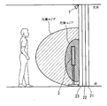
- the top view seen from the ceiling which shows the aspect by which the wireless electric power feeding system was installed in the house.
- the side view which shows the aspect by which the wireless electric power feeding system was installed in the house.
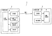
- the wireless power feeding system 1 includes a power feeding side device 2 and a power receiving side device 3.
- the power supply side device 2 includes a power supply control unit 4 (corresponding to a control unit), a power supply unit 5 (corresponding to a power supply unit), a power supply area storage unit 6 (corresponding to a power supply area storage unit), and an object position detection unit 7 ( And an informing unit 8 (corresponding to informing means).
- the power supply control unit 4 is composed of a well-known microcomputer having a CPU, RAM, ROM, I / O bus, and the like. By executing a computer program stored in the ROM or the like, a power supply side such as power supply control is provided. The overall operation of the device 2 is controlled.
- the power feeding unit 5 includes a power feeding coil and a power feeding capacitor, and feeds power to the power receiving side device 3 by magnetic field resonance with a power receiving coil and a power receiving capacitor of a power receiving unit 10 of the power receiving side device 3 described later.
- the power supply control unit 4 can control the output of power from the power supply unit 5.
- the power supply area storage unit 6 stores a power supply area from the power supply unit 5 of the power supply side device 2 to the power reception unit 10 of the power reception side device 3.
- the object position detection unit 7 includes a CCD (Charge-Coupled Device) image sensor, a CMOS (Complementary Metal-Oxide Semiconductor) image sensor, a pyroelectric sensor, an infrared sensor, and the like, and detects the position of an object (such as a person or an animal). In this case, the object position detection unit 7 sets an area including the above-described power supply area as a detection area.
- the power supply control unit 4 collates the power supply area stored in the power supply area storage unit 6 with the position of the object detected by the object position detection unit 7, so that the object is within the power supply area from outside the power supply area. It is possible to detect whether or not the vehicle has entered the power supply area, whether the vehicle has exited the power supply area, or the like.
- the notification unit 8 includes a device that notifies visual information such as a liquid crystal display and an LED and a device that notifies auditory information such as a speaker, and notifies the user of various types of notification information.
- the power receiving side device 3 includes a power receiving control unit 9, a power receiving unit 10, and an auxiliary power source 11.
- the power reception control unit 9 is composed of a well-known microcomputer having a CPU, RAM, ROM, I / O bus, and the like. By executing a computer program stored in the ROM or the like, power reception control or auxiliary power supply 11 is performed. The overall operation of the power receiving side device 3 such as power supply control from is controlled.
- the power receiving unit 10 includes a power receiving coil and a power receiving capacitor, rectifies high frequency generated by magnetic field resonance, generates direct current, and uses the generated direct current as power.
- the auxiliary power supply 11 stores electric power.
- the auxiliary power supply 11 starts supplying the stored power
- the auxiliary power supply 11 stores the power.
- the power supply is stopped. That is, the power receiving side device 3 operates using the received power as operating power during a period when the power receiving unit 10 receives power of a predetermined capacity or more from the power feeding unit 5 of the power feeding side device 2, and the power receiving unit 5 receives the predetermined power from the power feeding unit 5.
- the power receiving control unit 9 outputs a start command to the auxiliary power source 11 so that the power supplied from the auxiliary power source 11 operates as operating power.
- the configuration in which the auxiliary power source 11 is built in (integrated with) the power receiving side device 3 is described.
- the auxiliary power source 11 can be externally attached to the power receiving side device 3 ( The structure may be provided separately.
- the magnetic field resonance method for supplying power using magnetic field resonance is used.
- An electric field coupling method in which power is supplied using power may be used.
- the operation of the above configuration will be described with reference to FIGS.
- a case where the object to be detected by the object position detection unit 7 is a user (person) will be described.
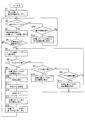
- the power supply control unit 4 executes main processing when the power supply side device 2 is powered on.
- the power supply control unit 4 shifts from the stopped state to the operation standby state (low power consumption operation state) (step S1), and detects the object position. It is determined whether the user is detected by the unit 7 (step S2).
- the power supply control unit 4 determines that the user exists in the detection area of the object position detection unit 7 when the user enters the detection area from outside the detection area of the object position detection unit 7, and the user detects If it is determined that the operation has been performed (step S2: YES), the operation standby state is shifted to the power supply standby state (step S3).
- the power supply standby state is a state in which necessary preparation is performed so that power supply from the power supply unit 5 to the power reception unit 10 can be started immediately.
- the power supply control unit 4 determines whether or not a start command for the power receiving side device 3 has been issued (step S4).
- the power supply control unit 4 has operated, for example, a start switch of the power receiving side device 3 (not shown, if the power receiving side device 3 is a television, a switch operated by the user to start watching the television), or If it is determined that the activation command for the power receiving device 3 has been issued because the activation time set in advance has been reached (step S4: YES), the position in the detection area of the user is specified, and the user detects the detection area. It is determined in which position (step S5).
- the power supply control unit 4 determines that the user has been detected (step S2: YES), but before determining that the activation command for the power receiving side device 3 has been issued, the user detects the object position detection unit 7. If it is determined that the user has not been detected because the user has left the area outside the detection area (step S2: NO), it is determined whether or not the user is in an operation standby state (step S14). If it is determined that it is not in the operation standby state (step S14: NO), the power supply standby state is shifted to the operation standby state (step S15), and it is determined again whether or not the user is detected by the object position detection unit 7 (step S2). ).
- the power supply control unit 4 sets a safe position outside the power supply area within the detection area, sets an area far from the power supply unit 5 within the power supply area as a caution position, and within the power supply area.
- an area close to the power feeding unit 5 is set as a dangerous position.
- the safe position is a position where the output of electric power transmitted when power is supplied from the power supply unit 5 to the power reception unit 10 is extremely small, that is, the possibility of radiation exposure is extremely small.
- the attention position is a position where the output of the power transmitted when the power supply unit 5 supplies power to the power reception unit 10 is medium, that is, the possibility of radiation exposure is medium.
- the dangerous position is a position where the output of electric power transmitted when power is supplied from the power supply unit 5 to the power reception unit 10 is extremely large, that is, the possibility of radiation exposure is extremely large.
- Step S6 When the power supply control unit 4 determines that the user is in the safe position (step S6: YES), for example, the notification unit 8 notifies the notification information that the power supply is started by voice guidance such as “start power supply”. (Step S9), power feeding from the power feeding unit 5 to the power receiving unit 10 is started (Step S10), and the process proceeds to a power feeding monitoring process (Step S11). If the power supply control unit 4 determines that the user is at the caution position (step S7: YES), the power supply control unit 4 does not start the power supply from the power supply unit 5 to the power reception unit 10, for example, “I am at the caution position”. Notification information that the user is at the attention position is notified from the notification unit 8 by voice guidance (step S12).
- the power supply control unit 4 determines that the user is in the dangerous position (step S8: YES)
- the power supply control unit 4 does not start the power supply from the power supply unit 5 to the power receiving unit 10, for example, “is in a dangerous position”.
- the notification unit 8 notifies the notification information that the user is in the dangerous position by voice guidance (step S13).
- the power supply control unit 4 may notify the user in which position the user is in another notification mode. For example, the power supply control unit 4 may notify that the user is in the safe position by turning on the green LED, and indicate that the user is in the attention position. You may make it alert
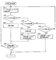
- step S21 When the power supply control unit 4 shifts from the main process to the monitoring process during power supply, the position of the user in the detection area is continuously specified, and the position in the detection area of the user is continuously determined (step) S21).
- step S22 YES
- step S25 the power supply control unit 4 continues to supply power from the power supply unit 5 to the power reception unit 10
- step S26 a command to stop the power reception side device 3 is issued. It is determined whether or not (step S26). If it determines with the electric power feeding control part 4 not having received the stop command of the power receiving side apparatus 3 (step S26: NO), it will determine continuously in which position a user is in a detection area (step S21).
- the user has operated a stop switch of the power receiving side device 3 (not shown, or a switch operated by the user to end the viewing of the television if the power receiving side device 3 is a television), or is set in advance. If it is determined that the stop command for the power receiving side device 3 has been issued due to the arrival of the stop time (step S26: YES), the power feeding monitoring process is terminated and the process proceeds to the main process (returns).
- step S23 If the power supply control unit 4 determines that the user is at the caution position (step S23: YES), the power supply control unit 4 continues to supply power from the power supply unit 5 to the power reception unit 10 (step S27), but notifies that the user is at the caution position. Information is notified from the notification unit 8 (step S28), and it is determined whether or not a stop command for the power receiving side device 3 has been issued (step S26). If the power supply control unit 4 determines that the user is in the dangerous position (step S24: YES), the power supply control unit 4 notifies the notification unit 8 of the notification information indicating that the user is in the dangerous position (step S29), and stops the power receiving side device 3. Without determining whether or not a command has been issued, the power supply monitoring process is terminated and the process proceeds to the main process.
- the power supply control unit 4 finishes the monitoring process during power supply and shifts to the main process, the power supply control unit 4 ends the power supply from the power supply unit 5 to the power receiving unit 10 (step S16), for example, voice guidance such as “power supply has been completed” Is notified from the notification unit 8 (step S17), the power supply standby state is shifted to the operation standby state (step S18), the process returns to step S2, and the object position detection unit 7 causes the user to It is determined again whether or not is detected.
- the power supply side device 2 power supply from the power supply side device 2 to the power reception side device 3 is started on the condition that the user is in a safe position. If the user moves from the caution position to the danger position, the user is informed that the movement to the caution position. Further, if the user moves from the caution position to the danger position, the user is informed that the movement to the danger position is performed. Force termination.
- the power supply may be forcibly terminated without telling the user that the position has moved to the caution position, or when moving from the caution position to the dangerous position. In addition, the power supply may not be forcibly terminated. Further, instead of classifying into the three positions of the safe position, the caution position, and the dangerous position, the position may be classified into two positions of the safe position and the dangerous position.
- the power supply may be resumed when the user moves (returns) from the dangerous position to the safe position.
- the power output is forcibly reduced, and the user moves from the dangerous position to the safe position (returned) ).
- the power output may be restored.
- the power reception control unit 9 outputs a start command to the auxiliary power source 11, thereby starting the supply of the electric power accumulated in the auxiliary power source 11.
- the supply of power stored in the auxiliary power supply 11 may be ended by outputting a termination command from the power reception control unit 9 to the auxiliary power supply 11.
- the mode is as shown in FIGS. 5A and 5B. That is, a power feeding board (power feeding layer) 22 and a light emitting board (light emitting layer) 23 are installed on the wall 21 in the room along the wall surface. Each functional block of the power supply side device 2 described in FIG. 1 is distributed on the power supply board 22 and the light emitting board 23.
- the power supply board 22 includes a power supply control unit 4, a power supply unit 5, and a power supply area storage unit. 6 is arranged, and the light emitting board 23 is provided with a notification unit 9.
- the object position detector 7 is arranged on the ceiling so that the detection area is the front area (user action area) of the light emitting board 23.
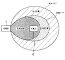
- the power receiving side device 3 is a household electrical appliance such as a television or an audio player installed in the room, and is activated by receiving power from the power supply board 22. That is, by supplying power to the power receiving side device 3 from the power supply board 22, the periphery of the power receiving side device 3 becomes a dangerous area including a dangerous position, and the periphery of the dangerous area becomes a caution area including a caution position.
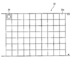
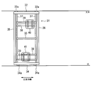
- the power supply board 22 has a plurality of installation spaces 22a partitioned in the horizontal direction and the vertical direction (in FIG. 6, 7 blocks in the vertical direction ⁇ 10 blocks in the horizontal direction).
- the unit device 24 having a power supply coil and a power supply capacitor constituting the power supply unit 5 can be arranged in the installation space 22a. That is, the user may arrange the unit device 24 in any installation space 22a according to the installation position of the power receiving side device 3 in the room. Of course, a plurality of unit devices 24 may be arranged.
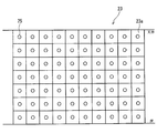
- the light emitting board 23 has installation spaces 23 a that are partitioned in the horizontal direction and the vertical direction so as to correspond to the installation space 22 a provided in the power supply board 22.
- LED25 which comprises the alerting
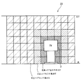
- the unit device 24 is arranged in the installation space 23 a of the light emitting board 23 corresponding to the part where the television as the power receiving side device 3 is installed, for example, and power is supplied from the unit device 24 to the power receiving side device 3 Then, the lighting color of LED25 changes according to the output of the electric power.
- the LED 25 is lit red, for example, to indicate that it is a dangerous area behind the power receiving side device 3 that is the area where the power output is the largest.
- the LED 25 is lit yellow, for example, to indicate that the area is a caution area around the danger area (the one that moves away from the power receiving side device 3).
- the LED 25 is lit in green, for example, to indicate that it is a safe area around the caution area (one that moves away from the power receiving side device 3).
- a moving unit 31 that can reciprocate horizontally along the wall surface.
- the moving unit 31 includes a ceiling side frame 32 having a guide 32a, an intermediate frame 33, a floor side frame 34 having wheels 34a, vertical frames 35 and 36, a pair of vertical guide rails 37, and a pair of horizontal guide rails 38. And 39, and device support members 40 and 41 are combined.
- the unit device 24 mounted on the device support member 40 or 41, the device support member 40 or 41 is moved in the horizontal direction along the horizontal guide rail 38 or 39, and the horizontal guide rail 38 or 39 is in the vertical direction.
- the unit device 24 is positioned by moving in the vertical direction along the guide rail 37.
- the position of the user relative to the power supply area when power is supplied from the power supply unit 5 of the power supply side device 2 to the power reception unit 10 of the power reception side device 3 is detected. According to the detected position, information on power feeding (whether it is a safe position, a caution position, or a dangerous position) is notified. Thus, if the user is in the power supply area, the possibility of radiation exposure is high. On the other hand, if the user is outside the power supply area, it can be notified that the possibility of radiation exposure is low. A user can be appropriately taught, and problems such as radiation exposure can be avoided in advance.
- the power supply is terminated, so that it is possible to avoid an adverse effect caused by continuing the power supply. Then, after the power supply is finished, for example, when the user moves from the dangerous position to the safe position, if the power supply is resumed, it is possible to quickly return to the state before the power supply is finished.
- the power output is decreased.
- the power output is restored.
- the same effect can be obtained.
- the configuration is not limited to being installed in a house, and may be installed in a vehicle.
- a charging holder that can be installed in a vehicle and can charge a portable device such as a portable information terminal or a mobile phone by wireless power feeding, information regarding power feeding from the charging holder to the portable device may be notified.
- the user is not limited to the detection target, and an animal (pet) or the like may be the detection target.
- the mode for notifying information related to power feeding is not limited to the mode of visual notification or the mode of auditory notification, and may be a mode of tactile notification using vibration or the like, for example.
- the user may be instructed whether the power receiving side device 2 is operating by receiving power from the power feeding side device 2 or the auxiliary power source 11.
- the power supply side device 2 may be installed on the house side, the power receiving side device 3 may be installed on the electric vehicle side, and the present invention may be applied to a system that supplies power from the housing facility to the electric vehicle.
Landscapes
- Engineering & Computer Science (AREA)
- Computer Networks & Wireless Communication (AREA)
- Power Engineering (AREA)
- Charge And Discharge Circuits For Batteries Or The Like (AREA)
Priority Applications (1)
| Application Number | Priority Date | Filing Date | Title |
|---|---|---|---|
| US14/420,693 US9800058B2 (en) | 2012-09-14 | 2013-06-26 | Wireless power supply system |
Applications Claiming Priority (2)
| Application Number | Priority Date | Filing Date | Title |
|---|---|---|---|
| JP2012202714A JP5958217B2 (ja) | 2012-09-14 | 2012-09-14 | 無線給電システム |
| JP2012-202714 | 2012-09-14 |
Publications (1)
| Publication Number | Publication Date |
|---|---|
| WO2014041729A1 true WO2014041729A1 (ja) | 2014-03-20 |
Family
ID=50277876
Family Applications (1)
| Application Number | Title | Priority Date | Filing Date |
|---|---|---|---|
| PCT/JP2013/003989 Ceased WO2014041729A1 (ja) | 2012-09-14 | 2013-06-26 | 無線給電システム |
Country Status (3)
| Country | Link |
|---|---|
| US (1) | US9800058B2 (https=) |
| JP (1) | JP5958217B2 (https=) |
| WO (1) | WO2014041729A1 (https=) |
Cited By (2)
| Publication number | Priority date | Publication date | Assignee | Title |
|---|---|---|---|---|
| US9479228B2 (en) | 2013-02-28 | 2016-10-25 | Denso Corporation | Unit device and wireless power supply information providing system |
| US20220032792A1 (en) * | 2020-07-29 | 2022-02-03 | Tdk Corporation | Power transmission device, wireless power transmission system, and information communication system |
Families Citing this family (8)
| Publication number | Priority date | Publication date | Assignee | Title |
|---|---|---|---|---|
| JP6367166B2 (ja) | 2015-09-01 | 2018-08-01 | 株式会社東芝 | 電子機器及び方法 |
| JP6809118B2 (ja) | 2016-10-13 | 2021-01-06 | 富士ゼロックス株式会社 | 電子機器、給電装置及び無線給電システム |
| JP6883423B2 (ja) * | 2016-12-28 | 2021-06-09 | 株式会社Lixil | 設備装置 |
| KR102464384B1 (ko) * | 2017-10-20 | 2022-11-08 | 삼성전자주식회사 | 무선 전력 송신 장치 및 그 제어 방법 |
| US12306285B2 (en) * | 2020-12-01 | 2025-05-20 | Energous Corporation | Systems and methods for using one or more sensors to detect and classify objects in a keep-out zone of a wireless-power transmission field, and antennas with integrated sensor arrangements |
| JP7810094B2 (ja) * | 2021-12-24 | 2026-02-03 | 豊田合成株式会社 | 送電装置 |
| US11916398B2 (en) | 2021-12-29 | 2024-02-27 | Energous Corporation | Small form-factor devices with integrated and modular harvesting receivers, and shelving-mounted wireless-power transmitters for use therewith |
| US12142939B2 (en) | 2022-05-13 | 2024-11-12 | Energous Corporation | Integrated wireless-power-transmission platform designed to operate in multiple bands, and multi-band antennas for use therewith |
Citations (2)
| Publication number | Priority date | Publication date | Assignee | Title |
|---|---|---|---|---|
| JP2010017041A (ja) * | 2008-07-06 | 2010-01-21 | Kyokko Denki Kk | 電力供給装置 |
| JP2011120410A (ja) * | 2009-12-04 | 2011-06-16 | Sony Corp | 送電装置、受電装置、および送電制御方法 |
Family Cites Families (5)
| Publication number | Priority date | Publication date | Assignee | Title |
|---|---|---|---|---|
| US8855554B2 (en) | 2008-03-05 | 2014-10-07 | Qualcomm Incorporated | Packaging and details of a wireless power device |
| US8629650B2 (en) | 2008-05-13 | 2014-01-14 | Qualcomm Incorporated | Wireless power transfer using multiple transmit antennas |
| JP5476211B2 (ja) | 2010-05-19 | 2014-04-23 | Necトーキン株式会社 | 送電装置、受電装置および非接触電力伝送及び通信システム |
| JP2012019666A (ja) | 2010-07-09 | 2012-01-26 | Sony Corp | ワイヤレス充電装置およびワイヤレス充電システム |
| JP5740200B2 (ja) * | 2011-04-22 | 2015-06-24 | 矢崎総業株式会社 | 共鳴式非接触給電システム、受電側装置及び送電側装置 |
-
2012
- 2012-09-14 JP JP2012202714A patent/JP5958217B2/ja not_active Expired - Fee Related
-
2013
- 2013-06-26 US US14/420,693 patent/US9800058B2/en not_active Expired - Fee Related
- 2013-06-26 WO PCT/JP2013/003989 patent/WO2014041729A1/ja not_active Ceased
Patent Citations (2)
| Publication number | Priority date | Publication date | Assignee | Title |
|---|---|---|---|---|
| JP2010017041A (ja) * | 2008-07-06 | 2010-01-21 | Kyokko Denki Kk | 電力供給装置 |
| JP2011120410A (ja) * | 2009-12-04 | 2011-06-16 | Sony Corp | 送電装置、受電装置、および送電制御方法 |
Cited By (3)
| Publication number | Priority date | Publication date | Assignee | Title |
|---|---|---|---|---|
| US9479228B2 (en) | 2013-02-28 | 2016-10-25 | Denso Corporation | Unit device and wireless power supply information providing system |
| US20220032792A1 (en) * | 2020-07-29 | 2022-02-03 | Tdk Corporation | Power transmission device, wireless power transmission system, and information communication system |
| US11897348B2 (en) * | 2020-07-29 | 2024-02-13 | Tdk Corporation | Power transmission device, wireless power transmission system, and information communication system |
Also Published As
| Publication number | Publication date |
|---|---|
| US20150236515A1 (en) | 2015-08-20 |
| JP2014060822A (ja) | 2014-04-03 |
| JP5958217B2 (ja) | 2016-07-27 |
| US9800058B2 (en) | 2017-10-24 |
Similar Documents
| Publication | Publication Date | Title |
|---|---|---|
| JP5958217B2 (ja) | 無線給電システム | |
| JP6411166B2 (ja) | スマートキーの位置に伴うワイヤレス充電制御方法 | |
| JP2013162624A (ja) | 電力供給システム | |
| KR102078073B1 (ko) | 급전장치 | |
| JP6418867B2 (ja) | 給電装置 | |
| KR20160123613A (ko) | 로봇 청소기 | |
| WO2014103191A1 (en) | Power supply apparatus, control method, program, and storage medium | |
| KR20150069254A (ko) | 이동단말기 무선충전기 | |
| US20130328407A1 (en) | Wireless power transmission apparatus, wireless power transmission system, and wireless communication apparatus | |
| KR101752642B1 (ko) | 급전장치로부터 무선으로 전력을 수신하는 전자기기 및 제어방법 | |
| KR20180115201A (ko) | 무선 전력 송신 장치, 무선으로 전력을 수신하는 전자 장치 및 그 동작 방법 | |
| JP2016010070A (ja) | モバイル機器およびその制御方法 | |
| US8648564B2 (en) | Power transmitting device | |
| US9749018B2 (en) | Power transmission apparatus and method for controlling power transmission | |
| US10027156B2 (en) | Electronic apparatus and charging method | |
| KR20210073419A (ko) | 이동 로봇 운용 서비스 시스템 | |
| JPWO2019012643A1 (ja) | 非接触給電システム | |
| JP6060516B2 (ja) | 電子機器および給電システム | |
| US20210175756A1 (en) | Power receiving apparatus, power transmitting apparatus, method for controlling same, and computer-readable medium | |
| CN103903404A (zh) | 底座和显示装置 | |
| JP6677520B2 (ja) | 情報処理装置、制御方法及びプログラム | |
| JP6314746B2 (ja) | ワイヤレス電力伝送用車両 | |
| JP2015136219A (ja) | 被充電機器、その制御方法、および制御プログラム、並びに非接触充電システム | |
| JP2014020790A (ja) | 情報端末 | |
| JP2014179746A (ja) | 携帯無線機器およびそれを用いた無接点充電システム |
Legal Events
| Date | Code | Title | Description |
|---|---|---|---|
| 121 | Ep: the epo has been informed by wipo that ep was designated in this application |
Ref document number: 13836866 Country of ref document: EP Kind code of ref document: A1 |
|
| WWE | Wipo information: entry into national phase |
Ref document number: 14420693 Country of ref document: US |
|
| NENP | Non-entry into the national phase |
Ref country code: DE |
|
| 122 | Ep: pct application non-entry in european phase |
Ref document number: 13836866 Country of ref document: EP Kind code of ref document: A1 |