WO2014041680A1 - 油冷式スクリュー圧縮機システム及び油冷式スクリュー圧縮機 - Google Patents
油冷式スクリュー圧縮機システム及び油冷式スクリュー圧縮機 Download PDFInfo
- Publication number
- WO2014041680A1 WO2014041680A1 PCT/JP2012/073622 JP2012073622W WO2014041680A1 WO 2014041680 A1 WO2014041680 A1 WO 2014041680A1 JP 2012073622 W JP2012073622 W JP 2012073622W WO 2014041680 A1 WO2014041680 A1 WO 2014041680A1
- Authority
- WO
- WIPO (PCT)
- Prior art keywords
- chamber
- seal
- screw
- bearing
- oil
- Prior art date
- Legal status (The legal status is an assumption and is not a legal conclusion. Google has not performed a legal analysis and makes no representation as to the accuracy of the status listed.)
- Ceased
Links
Images




Classifications
-
- F—MECHANICAL ENGINEERING; LIGHTING; HEATING; WEAPONS; BLASTING
- F04—POSITIVE - DISPLACEMENT MACHINES FOR LIQUIDS; PUMPS FOR LIQUIDS OR ELASTIC FLUIDS
- F04C—ROTARY-PISTON, OR OSCILLATING-PISTON, POSITIVE-DISPLACEMENT MACHINES FOR LIQUIDS; ROTARY-PISTON, OR OSCILLATING-PISTON, POSITIVE-DISPLACEMENT PUMPS
- F04C27/00—Sealing arrangements in rotary-piston pumps specially adapted for elastic fluids
- F04C27/008—Sealing arrangements in rotary-piston pumps specially adapted for elastic fluids for other than working fluid, i.e. the sealing arrangements are not between working chambers of the machine
- F04C27/009—Shaft sealings specially adapted for pumps
-
- F—MECHANICAL ENGINEERING; LIGHTING; HEATING; WEAPONS; BLASTING
- F04—POSITIVE - DISPLACEMENT MACHINES FOR LIQUIDS; PUMPS FOR LIQUIDS OR ELASTIC FLUIDS
- F04C—ROTARY-PISTON, OR OSCILLATING-PISTON, POSITIVE-DISPLACEMENT MACHINES FOR LIQUIDS; ROTARY-PISTON, OR OSCILLATING-PISTON, POSITIVE-DISPLACEMENT PUMPS
- F04C18/00—Rotary-piston pumps specially adapted for elastic fluids
- F04C18/08—Rotary-piston pumps specially adapted for elastic fluids of intermeshing-engagement type, i.e. with engagement of co-operating members similar to that of toothed gearing
- F04C18/12—Rotary-piston pumps specially adapted for elastic fluids of intermeshing-engagement type, i.e. with engagement of co-operating members similar to that of toothed gearing of other than internal-axis type
- F04C18/14—Rotary-piston pumps specially adapted for elastic fluids of intermeshing-engagement type, i.e. with engagement of co-operating members similar to that of toothed gearing of other than internal-axis type with toothed rotary pistons
- F04C18/16—Rotary-piston pumps specially adapted for elastic fluids of intermeshing-engagement type, i.e. with engagement of co-operating members similar to that of toothed gearing of other than internal-axis type with toothed rotary pistons with helical teeth, e.g. chevron-shaped, screw type
-
- F—MECHANICAL ENGINEERING; LIGHTING; HEATING; WEAPONS; BLASTING
- F04—POSITIVE - DISPLACEMENT MACHINES FOR LIQUIDS; PUMPS FOR LIQUIDS OR ELASTIC FLUIDS
- F04C—ROTARY-PISTON, OR OSCILLATING-PISTON, POSITIVE-DISPLACEMENT MACHINES FOR LIQUIDS; ROTARY-PISTON, OR OSCILLATING-PISTON, POSITIVE-DISPLACEMENT PUMPS
- F04C29/00—Component parts, details or accessories of pumps or pumping installations, not provided for in groups F04C18/00 - F04C28/00
- F04C29/02—Lubrication; Lubricant separation
- F04C29/021—Control systems for the circulation of the lubricant
-
- F—MECHANICAL ENGINEERING; LIGHTING; HEATING; WEAPONS; BLASTING
- F04—POSITIVE - DISPLACEMENT MACHINES FOR LIQUIDS; PUMPS FOR LIQUIDS OR ELASTIC FLUIDS
- F04C—ROTARY-PISTON, OR OSCILLATING-PISTON, POSITIVE-DISPLACEMENT MACHINES FOR LIQUIDS; ROTARY-PISTON, OR OSCILLATING-PISTON, POSITIVE-DISPLACEMENT PUMPS
- F04C29/00—Component parts, details or accessories of pumps or pumping installations, not provided for in groups F04C18/00 - F04C28/00
- F04C29/02—Lubrication; Lubricant separation
- F04C29/026—Lubricant separation
-
- F—MECHANICAL ENGINEERING; LIGHTING; HEATING; WEAPONS; BLASTING
- F04—POSITIVE - DISPLACEMENT MACHINES FOR LIQUIDS; PUMPS FOR LIQUIDS OR ELASTIC FLUIDS
- F04C—ROTARY-PISTON, OR OSCILLATING-PISTON, POSITIVE-DISPLACEMENT MACHINES FOR LIQUIDS; ROTARY-PISTON, OR OSCILLATING-PISTON, POSITIVE-DISPLACEMENT PUMPS
- F04C29/00—Component parts, details or accessories of pumps or pumping installations, not provided for in groups F04C18/00 - F04C28/00
- F04C29/12—Arrangements for admission or discharge of the working fluid, e.g. constructional features of the inlet or outlet
-
- F—MECHANICAL ENGINEERING; LIGHTING; HEATING; WEAPONS; BLASTING
- F16—ENGINEERING ELEMENTS AND UNITS; GENERAL MEASURES FOR PRODUCING AND MAINTAINING EFFECTIVE FUNCTIONING OF MACHINES OR INSTALLATIONS; THERMAL INSULATION IN GENERAL
- F16J—PISTONS; CYLINDERS; SEALINGS
- F16J15/00—Sealings
- F16J15/002—Sealings comprising at least two sealings in succession
-
- F—MECHANICAL ENGINEERING; LIGHTING; HEATING; WEAPONS; BLASTING
- F16—ENGINEERING ELEMENTS AND UNITS; GENERAL MEASURES FOR PRODUCING AND MAINTAINING EFFECTIVE FUNCTIONING OF MACHINES OR INSTALLATIONS; THERMAL INSULATION IN GENERAL
- F16J—PISTONS; CYLINDERS; SEALINGS
- F16J15/00—Sealings
- F16J15/16—Sealings between relatively-moving surfaces
- F16J15/164—Sealings between relatively-moving surfaces the sealing action depending on movements; pressure difference, temperature or presence of leaking fluid
Definitions
- the present invention relates to an oil cooled screw compressor system and an oil cooled screw compressor.
- Oil-cooled screw compressors are designed to supply oil to the compressor body for lubrication, cooling and shaft sealing, and are installed in industrial product manufacturing plants, chemical plants or petroleum refining plants, etc. , Used for the compression of various gases.
- the oil-cooled screw compressor disclosed in Patent Document 1 has a housing, and inside the housing, a screw chamber, seal chambers positioned on both sides of the screw chamber, and a bearing chamber connected to the screw chamber through the seal chamber Is divided.
- a pair of male and female screw rotors are accommodated in the housing in a state of being arranged parallel to each other.
- Each screw rotor includes a screw portion and a shaft portion coaxially extending from both ends of the screw portion.
- the pair of screw portions are disposed in the screw chamber so as to engage with each other, and form a compression chamber for compressing the target gas.
- the housing is formed with a suction port for sucking in gas from the outside, and a suction passage communicating the suction port and the compression chamber. Further, in the housing, a discharge port for discharging the compressed gas to the outside, and a discharge path communicating the discharge port and the compression chamber are formed.
- the suction passage is provided in communication with the compression chamber on one end side (suction side) of the compression chamber, and the discharge passage is provided in communication with the compression chamber on the other end side (discharge side) of the compression chamber .
- the shaft portion of the screw rotor is disposed in the seal chamber and the bearing chamber, and is rotatably supported by a radial bearing, for example, a slide bearing, disposed in the bearing chamber.
- a radial bearing for example, a slide bearing
- An external power source and an output shaft of a motor are connected to the shaft portion of the male screw rotor, and when the rotational force is input from the power source, the male screw rotor is rotated.
- the female screw rotor As the male screw rotor rotates, the female screw rotor also rotates in synchronization, and the male and female screw rotors rotate.
- a series of steps consisting of suctioning the gas from the suction passage into the compression chamber as the male and female screw rotors rotate, compressing the gas by reducing the volume of the compression chamber, and discharging the gas from the compression chamber to the discharge passage. The process is performed repeatedly.
- a bearing lubricating fluid is supplied to the bearings of the oil-cooled screw compressor.
- the housing is formed with a supply port for the bearing lubricating fluid, a discharge port, and a flow path for the bearing lubricating fluid that communicates the supply port and the discharge port with the bearing chamber.
- a tooth surface lubricating fluid is supplied to the screw portion.
- the housing is provided with a supply port for the tooth surface lubricating fluid, and a flow path for the tooth surface lubricating fluid that communicates the supply port with the screw chamber.
- a system for supplying a bearing lubricating fluid to an oil supply type screw compressor and a system for supplying a tooth surface lubricating fluid are separated.
- a mechanical seal as a shaft seal member is disposed in the seal chamber of the screw compressor so as to surround the shaft portion, and a bearing lubricating fluid is supplied to the mechanical seal.
- the mechanical seal seals between the bearing chamber and the screw chamber with the aid of the bearing lubricating fluid.
- Patent Document 1 the bearing lubricating fluid and the tooth surface lubricating fluid are separated by the shaft seal member. According to this configuration, even if the target gas is a corrosive gas, Patent Document 1 hardly contacts the bearing lubricating fluid with the target gas to prevent the deterioration of the bearing lubricating fluid due to the target gas, and the life of the bearing It is stated that shortening can be prevented. In particular, it is described that the use of the bearing lubricating fluid as the seal fluid can reliably prevent the inflow of the target gas into the bearing chamber.
- Patent Document 1 states that the amount of the target gas flowing into the bearing chamber through the shaft seal member is very small, so that the bearing lubricating fluid is not deteriorated or the bearing is not corroded directly. It is done.
- Patent Document 2 discloses, as a third embodiment, an oilless screw compressor in which a tooth surface lubricating fluid is not supplied to a screw portion.
- a shaft seal member comprising a plurality of carbon ring seals and a labyrinth seal is disposed in a seal chamber of the oil-free screw compressor, and a feed gas chamber provided at some midpoint of the shaft seal member is used as a process gas of discharge pressure Instead, an inert gas is provided.
- the discharge side seal chamber is in communication with the suction port through the suction port return line.
- the suction port is in communication with the upper portion of the oil supply tank storing the bearing lubricating fluid via the supply process gas communication line. According to this configuration, Patent Document 2 describes that even when compressing a target gas containing a corrosive component, the target gas can be prevented from coming into contact with the bearing, and deterioration of the lubricating oil can be made difficult. ing.
- the target gas supplied to the screw chamber is in contact with the mechanical seal, and the target gas may be mixed in the bearing lubricating fluid.
- the target gas contains a corrosive component
- the corrosive component may be mixed into the bearing lubricating fluid to reach the bearing, and the bearing may be corroded.
- high-pressure target gas is supplied to the discharge-side shaft seal member formed of a plurality of carbon ring seals, and the supplied target gas flows into the discharge-side bearing chamber. , Reach the bearing. Therefore, when the target gas contains a corrosive component, the discharge side bearing may be corroded. Although the target gas decompressed at the orifice is supplied to the suction-side shaft seal member consisting of a plurality of carbon ring seals, the supplied target gas also flows into the suction-side bearing chamber and is suctioned. Reach the bearing on the side. For this reason, when the target gas contains a corrosive component, the suction side bearing may be corroded.
- the inert gas is supplied to the flow passage chamber in the middle of the shaft seal member in place of the high-pressure target gas discharged from the oil-free screw compressor.
- the pressure of the inert gas supplied to the flow chamber is high.
- the suction port communicates with the upper portion of the oil supply tank through the supply process gas communication line, and the pressure of the oil supplied from the oil supply tank to the bearing is the suction pressure plus the pressure increase by the oil supply pump.
- the target gas is transferred to the bearing member after the screw compressor is stopped. If it is not supplied, the bearing lubricating fluid will flow from the bearing chamber into the screw chamber through the gap.
- the inflow of the bearing lubricating fluid into the screw chamber leads to a reduction in the amount of bearing lubricating fluid retained in the bearing lubricating fluid supply system when the bearing lubricating fluid and the tooth surface lubricating fluid are separated. For this reason, it is necessary to replenish the bearing lubricating fluid, which increases the operating cost of the screw compressor.
- the rotation of the male and female screw rotors is connected not to the engagement of the screw portion but to the shaft portion of the male and female screw rotors. It synchronizes via a pair of synchronized gears.
- the meshing portion of the screw portion has a gap and is not in contact, the compression efficiency is worse as compared with the oil-cooled screw compressor, and the high power rotation source is used as a power source. A high speed motor is required.
- the present invention has been made in view of the above-mentioned circumstances, and the object of the present invention is to provide an oil-cooled screw compressor at low cost while surely preventing deterioration of the bearing even if the target gas contains a corrosive component. It is an object of the present invention to provide an oil-cooled screw compressor system capable of operating and an oil-cooled screw compressor used in the system.
- an oil cooled screw compressor and a tooth surface lubricating fluid supply for supplying a tooth surface lubricating fluid to the oil cooled screw compressor System
- a bearing lubricating fluid supply system for supplying a bearing lubricating fluid separately from the tooth surface lubricating fluid to the oil cooled screw compressor
- the oil cooled screw compression for the oil cooled screw compressor
- a separated gas supply system for supplying a separated gas different from a target gas compressed by the machine, the oil-cooled screw compressor comprising a screw chamber, a seal chamber positioned on both sides of the screw chamber, the seal chamber A bearing chamber in communication with the screw chamber, a tooth surface lubricating fluid passage for supplying the tooth surface lubricating fluid to the screw chamber, and the bearing lubricating fluid in the bearing chamber
- a bearing lubricating fluid flow path for supplying is internally defined, a screw portion disposed in the screw chamber to form a compression chamber, and coaxially extending from both ends of the
- a separated gas supply gap is defined between the first seal unit and the second seal unit of the seal device, and the oil-cooled screw compressor During operation, the separation gas is supplied to the separation gas supply gap. Since the supplied separated gas leaks toward the screw chamber through the first seal unit, the first seal unit prevents the target gas from flowing into the bearing chamber during operation of the oil-cooled screw compressor. Contact of the target gas with the bearing lubricating fluid is also prevented. For this reason, even if the target gas contains a corrosive component, the deterioration of the bearing is reliably prevented.
- the supply pressure of the separated gas supplied to the discharge side seal chamber is returned from the discharge pressure of the target gas discharged from the oil-cooled screw compressor by returning the target gas to the compression chamber through the pressure equalization path. Even if it is not high, the first seal unit reliably prevents the passage of the target gas and the tooth surface lubricating fluid in the direction from the screw chamber to the bearing chamber. For this reason, the supply pressure of the separation gas can be set lower than the discharge pressure, and the consumption amount of the separation gas is suppressed.
- the target gas that has flowed into the discharge side seal chamber is returned to the compression chamber in a state of a pressure higher than the suction pressure through the pressure equalization path, so that a decrease in the efficiency of the oil-cooled screw compressor is suppressed .
- the screw compressor is operated at low cost.
- the housing is a screw casing defining the screw chamber, and the seal casing releasably coupled to the screw casing and defining the seal chamber and the pressure equalizing path. And a bearing casing separably connected to the screw casing via the seal casing and defining the bearing chamber.
- the seal casing is connected separably to the screw casing, and the bearing casing is connected separably via the seal casing.
- the first seal unit has a first labyrinth seal
- the second seal unit sequentially extends from the separated gas supply gap toward the bearing chamber.
- a second labyrinth seal, a first lip seal, and a second lip seal wherein the first lip seal is disposed to block the flow of fluid in a direction from the screw chamber toward the bearing chamber;
- the second lip seal is arranged to block the flow of fluid in the direction from the bearing chamber towards the screw chamber.
- the first lip seal restricts the flow of fluid in the direction from the screw chamber to the bearing chamber, the target can be obtained even if the separated gas is not supplied while the oil-cooled screw compressor is stopped. Gas is prevented from flowing into the bearing chamber, thereby preventing corrosion of the bearing. Furthermore, the second lip seal restricts the flow of fluid in the direction from the bearing chamber to the screw chamber, so that the bearing lubricating fluid may not be supplied with separated gas while the oil-cooled screw compressor is stopped. Is prevented from flowing into the screw chamber, thereby preventing the reduction of the bearing lubricating fluid. Therefore, the oil-cooled screw compressor can be operated at low cost.
- the oil-cooled screw compressor system further includes a control system that controls a supply pressure of the separated gas supplied to the oil-cooled screw compressor, the control system including the oil-cooled screw compression
- the supply pressure of the separation gas supplied to the machine is configured to be controlled so that the supply pressure of the separation gas is higher than the suction pressure and lower than the discharge pressure.
- the supply pressure of the separated gas is controlled to be higher than the suction pressure and lower than the discharge pressure, so the amount of consumption of the separated gas is reduced, and the oil-cooled screw compressor can be operated at low cost. can do.
- control system is configured such that a return pressure of the bearing lubricating fluid flowing out of the oil-cooled screw compressor is equal to or higher than the suction pressure, and the supply pressure of the separated gas.
- the supply pressure of the bearing lubricating fluid is configured to be controlled to be lower than that.
- the return pressure of the bearing lubricating fluid is controlled to be equal to or higher than the suction pressure and lower than the supply pressure of the separation gas, the pressure difference between the separation gas supply gap and the bearing chamber is The flow of the fluid from the bearing chamber to the screw chamber is restricted while keeping the size small and suppressing the consumption of the separated gas. Therefore, the oil-cooled screw compressor can be operated at low cost.
- the bearing lubricating fluid supply system has a storage tank for storing the bearing lubricating fluid at a storage pressure higher than the suction pressure, and the pressure in the storage tank The same kind of gas as the separated gas is used as a pressurized gas for raising the pressure to the storage pressure.
- the supply pressure of the bearing lubricating fluid can be made equal to or higher than the suction pressure with a simple configuration.
- the control system includes a suction pressure sensor for detecting the suction pressure, a control valve capable of adjusting the supply pressure of the separated gas, and a detection result by the suction pressure sensor. And a controller for operating the control valve.
- the supply pressure of the separation gas can be accurately controlled with a simple configuration.
- the oil-cooled screw compressor further comprises a volume control device
- the tooth-surface lubrication fluid supply system is configured to control the volume-control device with respect to the tooth-surface lubrication fluid. It is configured to supply a portion as the working fluid.
- the seal device is disposed between the first seal unit disposed on the screw chamber side of the seal chamber and the bearing chamber side of the seal chamber, and separated between the first seal unit and the first seal unit.
- a second seal unit defining a gas supply gap, wherein the seal chamber comprises a discharge side seal chamber positioned on the discharge side of the compression chamber and a suction side seal chamber positioned on the suction side of the compression chamber.
- a separate gas supply passage for supplying the separated gas to the separated gas supply gap is defined inside the housing.
- the oil-cooled system has a pressure higher than a suction pressure of the target gas sucked into the oil-cooled screw compressor and a region closer to the screw chamber than the first seal unit in the discharge side seal chamber.
- a pressure equalizing path configured to communicate with the compression chamber in a lower pressure state than the discharge pressure of the target gas discharged from the screw compressor is defined, and the pressure equalizing path is provided from the screw chamber to the discharge side.
- An oil cooled screw compressor is provided, characterized in that a check valve is arranged which restricts the flow of fluid in the direction towards the sealing chamber.
- a separated gas supply gap is defined between the first seal unit and the second seal unit of the seal device, and the operation of the oil-cooled screw compressor At the same time, the separation gas is supplied to the separation gas supply gap. Since the supplied separated gas leaks toward the screw chamber through the first seal unit, the first seal unit prevents the target gas from flowing into the bearing chamber during operation of the oil-cooled screw compressor. Contact of the target gas with the bearing lubricating fluid is also prevented.
- the supply pressure of the separated gas supplied to the discharge side seal chamber is returned from the discharge pressure of the target gas discharged from the oil-cooled screw compressor by returning the target gas to the compression chamber through the pressure equalization path. Even if it is not high, the first seal unit reliably prevents the passage of the target gas and the tooth surface lubricating fluid in the direction from the screw chamber to the bearing chamber. For this reason, the supply pressure of the separation gas can be set lower than the discharge pressure, and the consumption amount of the separation gas is suppressed.
- the target gas that has flowed into the discharge side seal chamber is returned to the compression chamber in a state of a pressure higher than the suction pressure through the pressure equalization path, so that a decrease in the efficiency of the oil-cooled screw compressor is suppressed .
- the oil-cooled screw compressor is operated at low cost.
- the housing is a screw casing defining the screw chamber, and a seal casing separably connected to the screw casing and defining the seal chamber and the pressure equalizing passage. And a bearing casing releasably connected to the screw casing via the seal casing and defining the bearing chamber.
- the seal casing is connected separably to the screw casing, and the bearing casing is connected separably via the seal casing, and the same screw casing and bearing as the conventional oil-cooled screw compressor A casing can be used. Therefore, the versatility of the parts of the oil-cooled screw compressor is high, and the price of the oil-cooled screw compressor can be reduced.
- the first seal unit has a first labyrinth seal
- the second seal unit is configured to move in a second direction from the separation gas supply gap toward the bearing chamber.
- a labyrinth seal, a first lip seal, and a second lip seal wherein the first lip seal is disposed to block the flow of fluid in a direction from the screw chamber toward the bearing chamber;
- a two lip seal is arranged to block the flow of fluid in the direction from the bearing chamber towards the screw chamber.
- the target can be obtained even if the separated gas is not supplied while the oil-cooled screw compressor is stopped. Gas is prevented from flowing into the bearing chamber, thereby preventing corrosion of the bearing.
- the second lip seal restricts the flow of fluid in the direction from the bearing chamber to the screw chamber, so that the bearing lubricating fluid may not be supplied with separated gas while the oil-cooled screw compressor is stopped. Is prevented from flowing into the screw chamber, thereby preventing the reduction of the bearing lubricating fluid. Therefore, the oil-cooled screw compressor can be operated at low cost.
- an oil-cooled screw capable of operating an oil-cooled screw compressor at low cost while reliably preventing deterioration of the bearing even if the target gas contains a corrosive component
- a compressor system and an oil cooled screw compressor used in the system are provided.
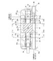
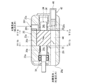
- FIG. 2 is a schematic cross-sectional view of the oil-cooled screw compressor taken along line II-II in FIG.
- A is a figure which shows the rough end surface of the suction side seal casing which follows the IIIa-IIIa line in FIG. 2
- (b) is a suction side bearing which follows the IIIb-IIIb line in FIG.
- FIG. 3 is a view showing a schematic end face of a casing
- FIG. 2 (c) is a view showing a schematic end face of a discharge side seal casing along a line IIIc-IIIc in FIG.
- FIG. 3 is a view showing a schematic end face of the discharge side bearing casing, taken along the line IIId-IIId in FIG.
- sticker apparatus provided in the discharge side seal chamber of the oil-cooled type screw compressor of FIG.
- sticker apparatus provided in the suction side sealing chamber of the oil-cooled type screw compressor of FIG.
- An oil-cooled screw compressor provided with an oil-cooled screw compressor applied to a target gas containing no corrosive component and having a suction-side bearing housing and a discharge-side bearing housing of the oil-cooled screw compressor in FIG.
- FIG. 1 is a diagram showing a schematic configuration of a system.
- FIG. 7 is a schematic cross-sectional view of the oil-cooled screw compressor, taken along line VII-VII in FIG. (A) is a figure which shows the rough end surface of the suction side bearing casing which follows the VIIIa-VIIIa line in FIG. 7, (b) is a discharge side bearing which follows the VIIIb-VIIIb line in FIG. It is a figure which shows the rough end surface of a casing.
- FIG. 2 is a view showing an example in which a supply system of working fluid for a hydraulic cylinder is changed in the system of FIG.
- FIG. 7 shows another variant of the working fluid supply system for the hydraulic cylinder.
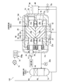
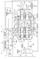
- FIG. 1 is a view showing a schematic configuration of an oil-cooled screw compressor system according to an embodiment.
- the oil-cooled screw compressor system includes an oil-cooled screw compressor (hereinafter also referred to as a screw compressor) 10, a tooth surface lubricating fluid supply system 12, a bearing lubricating fluid supply system 14, and a separated gas supply system 16 , And a control system 18.
- FIG. 1 shows a schematic cross section of the screw compressor 10 along a horizontal plane
- FIG. 2 shows a schematic cross section of the screw compressor 10 along a vertical plane
- the screw compressor 10 has a housing 20, and inside the housing 20, a screw chamber 20a, a suction side seal chamber 20b connected to one end of the screw chamber 20a, and a suction side seal chamber 20b
- a suction side bearing chamber 20c communicating with the screw chamber 20a via the discharge chamber 20a
- a discharge side seal chamber 20d communicating with the other end of the screw chamber 20a
- a discharge side bearing chamber 20e communicating with the screw chamber 20a via the discharge side seal chamber 20d. Is divided.
- the housing 20 has a suction port 20f and a discharge port 20g opened respectively toward the outside, and when the screw compressor 10 is operated, low pressure (suction pressure) gas to be compressed through the suction port 20f (hereinafter referred to as target The gas is sucked and the target gas of high pressure (discharge pressure) compressed through the discharge port 20g is discharged.
- a suction passage 20h for communicating the suction port 20f with one end (suction end) of the screw chamber 20a is defined in the housing 20, and communicates with the other end (discharge end) side of the screw chamber 20a.
- the discharge passage 20i is divided.
- the housing 20 includes a screw casing 22a defining the screw chamber 20a, a suction side seal casing 22b defining the suction side seal chamber 20b, and a suction side bearing casing 22c defining the suction side bearing chamber 20c.
- the casing 22b and the suction side bearing casing 22c are separably connected in series in this order by bolts.
- a pair of male screw rotors 24 and a female screw rotor 26 are rotatably accommodated.
- the male screw rotor 24 and the female screw rotor 26 are arranged such that their rotational axes are parallel to each other.
- the male screw rotor 24 and the female screw rotor 26 have suction side shaft portions 24b and 26b coaxially and integrally extending from one end (suction side end) of the screw portions 24a and 26a and the screw portions 24a and 26a, It has discharge side axial part 24c, 26c coaxially and integrally extended from the other end (discharge side end) of screw part 24a, 26a.
- the screw portion 24a of the male screw rotor 24 has a plurality of helical ridges on the outer periphery
- the screw portion 26a of the female screw rotor 26 has a plurality of helical grooves on the outer periphery.
- the screw portions 24a and 26a are disposed in the screw chamber 20a in parallel with each other in a mutually meshed state.
- the discharge side shaft portion 24 c of the male screw rotor 24 penetrates the end wall of the housing 20 in an airtight manner and protrudes to the outside.
- a hydraulic motor or an electric motor, for example, is connected to the discharge side shaft portion 24c as a power source, and a rotational force is input from the power source to the discharge side shaft portion 24c.
- the male screw rotor 24 rotates, and the female screw rotor 26 rotates in synchronization by the engagement of the screw portions 24a and 26a.
- the plurality of ridges and grooves of the screw portions 24a, 26a define a plurality of compression chambers in the screw chamber 20a.
- a suction passage 20h for connecting the suction port 20f and the compression chamber is formed in the suction side seal casing 22b and the suction side bearing casing 22c.
- the suction passage 20h has a suction port opened at the end face of the suction side seal casing 22b opposed to the screw casing 22a.
- FIG. 3B in the end face of the suction side bearing casing 22c opposed to the suction side seal casing 22b, an opening of the same shape as the suction port is formed corresponding to the suction passage 20h. .
- a discharge passage 20i for connecting the discharge port 20g and the compression chamber is formed inside the discharge side seal casing 22d and the discharge side bearing casing 22c.
- the discharge passage 20i has a discharge port opened at the end face of the discharge side seal casing 22b opposed to the screw casing 22a.
- an opening having the same shape as the discharge port is formed corresponding to the discharge path 20i. It is done.
- the discharge port opened in the discharge side seal casing 22d has an axial communication portion communicating with the compression chamber in the axial direction at the top, but the opening of the end face of the discharge side bearing casing 22e communicates with the axial direction Have no department.
- the compression chamber intermittently communicates with the suction port of the suction passage 20h with the synchronous rotation of the screw portions 24a and 26a, and communicates with the discharge port of the discharge passage 20i at a timing different from that of the suction port.
- the volume of the compression chamber gradually decreases with the synchronous rotation of the screw portions 24a and 26a immediately after the communication with the suction port is shut off, whereby the target gas is compressed in the compression chamber.
- tooth surface lubricating fluid passage 30 is formed in the housing 20, which communicates the screw chamber 20a with the outside.
- slide bearings 32 are respectively disposed in the suction side bearing chamber 20c and the discharge side bearing chamber 20e as radial bearings.
- an angular ball bearing 34 is disposed in the discharge side bearing chamber 20 e. The angular ball bearing 34 is fitted to the discharge side shaft portion 24c of the male screw rotor 24 and the discharge side shaft portion 26c of the female screw rotor 26, and generates a thrust load (compression reaction force) generated by the compression of the target gas in the compression chamber.
- a thrust load compression reaction force
- a bearing lubricating fluid is supplied to the slide bearing 32 and the angular ball bearing 34.
- a bearing lubricating fluid flow path 36 is formed in the housing 20 for communicating the suction side bearing chamber 20c and the discharge side bearing chamber 20e with the outside.
- the bearing lubricating fluid is supplied from the suction side discharge chamber 20c and the discharge side bearing chamber 20e to the bearing lubricating fluid flow path 36 for supplying the bearing lubricating fluid to the suction side discharge chamber 20c and the discharge side bearing chamber 20e.
- a piston (balance piston) 38 is attached to the suction side shaft portion 24 b of the male screw rotor 24.
- a part of the suction side bearing chamber 20 c is partitioned as a cylinder (balance cylinder), and the balance cylinder accommodates the balance piston 38 slidably in the axial direction of the male screw rotor 24.
- the thrust load can be reduced by adjusting the pressure in the balance cylinder.
- the housing 20 is formed with a pressure fluid supply passage 40 communicating the balance cylinder with the outside.
- the pressure in the balance cylinder is adjustable by the pressure of the pressure fluid supplied through the pressure fluid supply passage 40.
- the pressure fluid supply passage 40 is provided in the cover member that closes the open end of the suction side bearing casing 22c.
- the screw compressor 10 is provided with a capacity control device 42.
- the displacement control device 42 has a displacement control piston 44, and the displacement control piston 44 is accommodated in a cylinder (a displacement control cylinder) partitioned in the housing 20.
- the displacement control cylinder extends along the screw chamber 20a and communicates with the discharge passage 20i.
- the end of the displacement control cylinder on the discharge passage 20i side constitutes a radial communication portion communicating with the compression chamber in the radial direction. Therefore, the target gas compressed in the compression chamber can flow into the discharge passage 20i through the radial communication portion of the discharge port and the radial communication portion of the volume control cylinder.
- the displacement control piston 44 is disposed slidably in the axial direction of the male screw rotor 24 and the female screw rotor 26.
- the displacement control piston 44 is connected to, for example, a hydraulic cylinder 46 as a drive device, and is reciprocated within the displacement control cylinder by the hydraulic cylinder 46.
- this displacement control device 42 by controlling the hydraulic cylinder 46 to adjust the position of the displacement control piston 44, the axial length of the compression chamber, in other words, the compression start timing in the compression chamber is adjusted. , The capacity of the screw compressor 10 is adjusted.
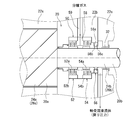
- FIG. 4 schematically shows the configuration of a seal device 50 for the discharge side shaft portions 24c, 26c disposed in the discharge side seal chamber 20d.
- the seal device 50 includes a first seal unit and a second seal unit.
- the first seal unit is disposed on the side of the screw chamber 20a
- the second seal unit is disposed on the side of the discharge bearing chamber 20e.
- the first seal unit has a first labyrinth seal 52 as a noncontact seal member.
- the second seal unit has a second labyrinth seal 54 as a noncontact seal member and has a lip seal 56 as a contact seal member.
- the first labyrinth seal 52, the second labyrinth seal 54, and the lip seal 56 are arranged in this order from the screw chamber 20a side.
- the first labyrinth seal 52 and the second labyrinth seal 54 are fixed to the inner peripheral surface of the discharge side seal chamber 20d and the rotary members 52a and 54a fixed to the discharge side shaft portions 24c and 26c. It consists of members 52b and 54b.
- the rotating members 52a and 54a include a sleeve portion fitted to the discharge side shaft portions 24c and 26c, and a plurality of annular protrusions which respectively project radially outward from the sleeve portion and are separated from each other in the axial direction of the sleeve portion. Have.
- the fixing members 52b and 54b are a sleeve portion fitted to the inner peripheral surface of the discharge side seal chamber 20d, and a plurality of annular members protruding radially inward from the sleeve portion and mutually separated in the axial direction of the sleeve portion. And a protrusion.
- the rotating members 52a and 54a and the fixing members 52b and 54b are arranged such that the protrusions are engaged with a minute gap.
- a separation gas supply gap 58 is provided between the first seal unit and the second seal unit. Specifically, the first labyrinth seal 52 and the second labyrinth seal 54 are disposed separately from each other in the axial direction of the discharge side shaft portions 24c and 26c, and the separation gas supply gap 58 is provided between them. There is. A separation gas supply passage 59 for supplying the separation gas to the separation gas supply gap 58 is formed in the housing 20.
- the lip seal 56 includes a sleeve 56a fitted to the inner peripheral surface of the discharge side seal chamber 20d, and a first wrap 56b and a second wrap 56c protruding radially inward from the sleeve 56a.
- the first wrap portion 56b is made of an elastic material and has a trumpet shape.
- the outer peripheral portion of the first wrap portion 56b is held by the sleeve portion 56a, and the inner peripheral portion of the first wrap portion 56b elastically contacts the outer peripheral surface of the discharge side shaft portions 24c and 26c.
- the first wrap portion 56b has a cross-sectional shape that is curved so as to approach the screw chamber 20a as it approaches the discharge side shaft portions 24c and 26c. Therefore, the first wrap portion 56b is arranged to restrict the flow of fluid in the direction from the screw chamber 20a to the discharge side bearing chamber 20e.
- the second wrap portion 56c is also made of an elastic material and has a trumpet shape.
- the outer peripheral portion of the second wrap portion 56c is held by the sleeve portion 56a, and the inner peripheral portion of the second wrap portion 56b elastically contacts the outer peripheral surface of the discharge side shaft portions 24c and 26c.
- the second wrap portion 56c disposed closer to the discharge bearing chamber 20e than the first wrap portion 56b has a cross-sectional shape that is curved so as to approach the discharge side bearing chamber 20e as it approaches the discharge side shaft portions 24c and 26c. Therefore, the second wrap portion 56c is arranged to restrict the flow of fluid from the discharge side bearing chamber 20e to the screw chamber 20a.
- the fixing member 52 b of the first labyrinth seal 52 and the fixing member 54 b of the second labyrinth seal 54 are configured by separate members, but may be configured by one member.
- the rotation member 52a and the rotation member 54a may be configured by one member.
- the rotating members 52a and 54a may be integrally formed on the outer peripheral surface of the discharge side shaft portions 24c and 26c.
- one lip seal 56 has the first wrap portion 56 b and the second wrap portion 56 c which are disposed in the opposite direction to each other, and each constitutes a wrap seal.
- Two lip seals with two wraps may be arranged opposite one another.
- the housing 20 is formed with a pressure equalizing passage 60 which communicates the discharge side seal chamber 20 d with the screw chamber 20 a.
- One end of the pressure equalizing path 60 opens in the region of the discharge side seal chamber 20 d closer to the screw chamber 20 a than the first labyrinth seal 52, and the other end opens in the end wall of the screw chamber 20 a.
- the opening position of the other end of the pressure equalizing path 60 is equal to the compression chamber (the hatched area in FIG. 4) immediately after the communication with the suction path 20h is interrupted.
- the passage 60 is set to communicate. In the present embodiment, referring also to FIG.
- the pressure equalizing path 60 is provided only between the discharge side seal chamber 20 d into which the discharge side shaft portion 26 c of the female screw rotor 26 is inserted and the screw chamber 20 a.
- the two discharge side seal chambers 20 d communicate with each other through the communication passage 61.
- the check valve 62 is disposed in the pressure equalizing path 60, and the check valve 62 allows the flow of fluid in the direction from the discharge side seal chamber 20d to the screw chamber 20a, and the flow of fluid in the reverse direction Is configured to regulate.
- the check valve 62 is a normally open type, and is closed only when the pressure in the compression chamber communicating with the pressure equalizing passage 60 is higher than the pressure in the discharge side seal chamber 20 d.
- FIG. 5 schematically shows the seal device 50 disposed in the suction side seal chamber 20b.
- the configuration of the seal device 50 disposed in the suction side seal chamber 20b is substantially the same as the configuration of the seal device 50 disposed in the discharge side seal chamber 20d, so the same reference numerals are given to the same components. Omit. However, a pressure equalizing passage and a check valve are not provided between the suction side seal chamber 20b and the screw chamber 20a.
- the tooth surface lubricating fluid supply system 12 has a gas-liquid separation device 64.
- the inlet of the gas-liquid separator 64 is connected to the discharge port 20g of the screw compressor 10, for example, via a conduit.
- the gas-liquid separation device 64 has a separation tank 66, and a filter 68 for separating the target gas and the tooth surface lubricating fluid is disposed above the separation tank 66.
- a reservoir 70 for temporarily storing the separated tooth surface lubricating fluid is provided, and the inlet of the gas-liquid separator 64 is a separation tank 66 between the reservoir 70 and the filter 68. It communicates with the inside of the
- a gas outlet for the target gas is provided, and the high-pressure target gas separated from the gas outlet is supplied to the outside.
- the bottom of the separation tank 66 is provided with a liquid outlet for the tooth surface lubricating fluid, and the liquid outlet is connected to the tooth surface lubricating fluid channel 30 of the screw compressor 10, for example, via a conduit.
- the pressure in the separation tank 66 is equal to the pressure of the compressed target gas, ie the discharge pressure, and the flank lubricating fluid is supplied to the screw compressor 10 at the discharge pressure.
- a tooth surface lubricating fluid is used as the working fluid of the drive device of the displacement control device 42.
- the lower part of the separation tank 66 is connected to the inlet of the switching valve 72 through a conduit, and the outlet of the switching valve 72 is connected to the suction port 20f through a conduit.
- the switching valve 72 has two switching ports, and the two switching ports are respectively connected to two ports of the hydraulic cylinder 46.
- the position of the valve body of the switching valve 72 can be externally controlled, and the displacement of the screw compressor 10 can be controlled by controlling the position of the valve body.
- the bearing lubricating fluid supply system 14 has a storage tank 74 capable of storing the bearing lubricating fluid at a pressure higher than atmospheric pressure.
- the outlet of the storage tank 74 is connected to the forward portion of the bearing lubricating fluid channel 36, for example, via a conduit.
- a pump 76 for generating a flow of bearing lubricating fluid in a direction from the storage tank 74 toward the screw compressor 10 and a heat exchanger 78 for cooling the bearing lubricating fluid are interposed. It is disguised.
- the conduit is branched downstream of the heat exchanger 78 and is also connected to the pressure fluid supply passage 40 of the screw compressor 10. That is, one branched conduit (first conduit) is connected to the forward portion of the bearing lubricating fluid channel 36 and the other conduit (second conduit) is also connected to the pressure fluid supply channel 40.
- a control valve 80 capable of adjusting the pressure of the bearing lubricating fluid is interposed in the middle of the first conduit.
- the inlet of the storage tank 74 is in communication with the return path portion of the bearing lubricating fluid channel 36 through, for example, a conduit. Accordingly, the bearing lubricating fluid that has flowed out of the screw compressor 10 flows into the storage tank 74 and is then supplied to the screw compressor 10 again.
- one outlet of the return path portion of the bearing lubricating fluid channel 36 is provided in each of the suction side seal casing 22 b and the discharge side seal casing 22 d. Then, in order to communicate between the suction side bearing chamber 20c and the discharge side bearing chamber 20e and the outlet of the return path portion of the bearing lubricating fluid flow path 36, the return path portion of the bearing lubricating fluid flow path 36 is the suction side seal casing 22b. It is formed inside the suction side bearing casing 22c, the discharge side seal casing 22d, and the discharge side bearing casing 22e.
- one inlet of the forward passage portion of the bearing lubricating fluid channel 36 is provided in the discharge side bearing casing 22e. Then, in order to communicate between the suction side bearing chamber 20c and the discharge side bearing chamber 20e and the inlet of the forward path portion of the bearing lubricating fluid flow path 36, the forward path portion of the bearing lubricating fluid flow path 36 It is formed inside the side seal casing 22b, the suction side bearing casing 22c, the discharge side seal casing 22d, and the discharge side bearing casing 22e.
- the separation gas supply system 16 is configured to supply separation gas to the screw compressor 10 during operation of the screw compressor 10.
- the separation gas for example, an inert gas such as nitrogen can be used.
- the separation gas supply system 16 has, for example, a compressor or a high pressure cylinder as the separation gas supply source 82, and can supply the screw compressor 10 with a high pressure separation gas.
- the separation gas supply source 82 is connected to the separation gas supply passage 59 of the screw compressor 10, for example, via a conduit.
- a control valve 84 is interposed, and the opening pressure of the control valve 84 can be adjusted to adjust the supply pressure of the separation gas to the separation gas supply passage 59.
- one separation gas supply passage 59 is provided for one seal device 50, and the separation gas is supplied to each separation gas supply passage 59 via the control valve 84.
- the separated gas supply source 82 is connected to the storage tank 74, for example, via a conduit.
- a control valve 86 is interposed in the middle of the conduit, and by adjusting the degree of opening of the control valve 86, the supply pressure of the separated gas to the storage tank 74 can be adjusted. That is, the separation gas is also used as a pressurized gas for raising the pressure of the storage tank 74.
- the pressure in the storage tank 74 can be adjusted, and thus, the pressure of the bearing lubricating fluid supplied to the screw compressor 10 can be adjusted. it can.
- the control system 18 comprises a controller 88 and a plurality of sensors.
- the control device 88 is configured by, for example, a computer including a central processing unit, a memory, an external storage device, an input / output device, and the like.
- the control system 18 uses, for example, a suction pressure sensor 90a for detecting the suction pressure of the target gas sucked to the suction port 20f as a sensor for providing information for control to the control device 88, and the discharge port 20g.
- a discharge pressure sensor 90b for detecting the discharge pressure of the discharged target gas
- a primary pressure sensor 90c for detecting the pressure of the bearing lubricating fluid supplied to the pressure fluid supply passage 40
- a bearing lubricating fluid passage Secondary pressure sensor 90d for detecting the pressure of the bearing lubricating fluid supplied to the forward path portion of 36 and the pressure (return pressure) of the bearing lubricating fluid flowing out of the return path portion of the bearing lubricating fluid passage 36
- Pressure sensor 90e for example, a suction pressure sensor 90a for detecting the suction pressure of the target gas sucked to the suction port 20f as a sensor for providing information for control to the control device 88, and the discharge port 20g.
- a discharge pressure sensor 90b for detecting the
- the controller 88 integrally controls the operation of the entire screw compressor 10 system based on the external command and the information detected by the sensor.
- the control device 88 controls the power source to adjust the amount of power supplied to the screw compressor 10, and controls a pump or the like (not shown) to adjust the amount of refrigerant supplied to the heat exchanger. Control the amount of supply of bearing lubricating fluid, and further, control the switching valve 72 to adjust the capacity of the screw compressor 10
- control device 88 adjusts the opening degree of the control valve 84 to adjust the supply pressure of the separated gas to the separated gas supply path 59, adjusts the opening degree of the control valve 86, and The pressure is adjusted to adjust the supply pressure of the bearing lubricating fluid to the pressure fluid supply path 40. Furthermore, the controller 88 adjusts the opening degree of the control valve 80 to adjust the supply pressure of the bearing lubricating fluid to the forward portion of the bearing lubricating fluid channel 36.
- the controller 88 controls the supply pressure of the separation gas supplied to the separation gas supply path 59 (separation gas supply pressure) to be higher than the suction pressure detected by the suction pressure sensor 90a. , Adjust the opening degree of the control valve 84.
- the separation gas supply pressure is higher than the suction pressure by about 0.04 MPa to 0.11 MPa. To do control. In this range, the separation gas supply pressure can be suppressed lower than the discharge pressure.
- the return pressure of the bearing lubricating fluid flowing out of the screw compressor 10, detected by the return pressure sensor 90e is equal to or higher than the suction pressure detected by the suction pressure sensor 90a.
- the control device 88 adjusts the opening degree of the control valve 86 and the control valve 80 so as to be lower than the above.
- the pressure acting on the suction side bearing chamber 20c side and the discharge side bearing chamber 20e side of the second lip portion 56c is a screw than the first labyrinth seal 52 in the suction side seal chamber 20b and the discharge side seal chamber 20d.
- the controller 88 controls the return pressure to be substantially equal to the pressure in the region on the chamber 20a side. For example, when the suction pressure is in the range of 0.1 MPa to 0.6 MPa, the control device 88 performs control such that the return pressure of the bearing lubricating fluid becomes about 0.01 MPa to 0.7 MPa.
- the separation gas supply gap 58 is defined between the first seal unit and the second seal unit of the seal device 50, and the separation gas supply gap is set during operation of the screw compressor 10. Separate gas is supplied to 58.
- the target gas is sucked by the first seal unit 20c and the discharge side bearing chamber 20e by the first seal unit when the screw compressor 10 is operated. And the contact of the target gas with the bearing lubricating fluid is also prevented. For this reason, even if the target gas contains a corrosive component, the deterioration of the bearing is reliably prevented.
- the target gas that has flowed into the discharge side seal chamber 20d is returned to the compression chamber in a state higher than the suction pressure through the pressure equalizing passage 60, so that the efficiency of the screw compressor 10 is prevented from being reduced. . Thereby, the screw compressor 10 is operated at low cost.
- the suction side seal casing 22b and the discharge side seal casing 22d are separably connected to the screw casing 22a, and the suction side seal casing 22b and the discharge side
- the suction side bearing casing 22c and the discharge side bearing casing 22e are connected in a separable manner via the seal casing 22d.
- the housing 20 by the plurality of divisible casings, between the screw compressor 10 and the oil-cooled screw compressor used to compress the target gas containing no corrosive component,
- the screw casing 22a and the suction side and discharge side bearing casings 22c and 22d can be made common. Therefore, the versatility of the parts of the screw compressor 10 is high, and the cost of the screw compressor system can be reduced.
- FIG. 6 shows a schematic configuration of an oil-cooled screw compressor system using the oil-cooled screw compressor 100 used to compress a target gas containing no corrosive component.
- a surface lubricating fluid and a bearing lubricating fluid are supplied to the screw compressor 100 by one lubricating fluid supply system 102.
- symbol is attached
- FIG. 7 shows a schematic cross section of the screw compressor 100 along the line VII-VII in FIG. 1, and referring to FIGS. 6 and 7, the screw compressor 100 is substantially the same as the screw compressor 10.
- a suction side bearing casing 22c and a discharge side bearing casing 22e are provided.
- screw compressor 100 differs from screw compressor 10 in that it does not have suction side and discharge side seal casings 22b and 22d. Further, along with this, the lengths of the suction side shaft portions 24b and 26b and the discharge side shaft portions 24c and 26c of the male and female screw rotors 24 and 26 are different between the screw compressor 10 and the screw compressor 100.
- FIG. 8A and 8B schematically show the end faces of the suction side bearing casing 22c and the discharge side bearing casing 22e used in the screw compressor 100.
- the discharge port of the discharge passage 20i is opened in the discharge side bearing casing 22e, and the discharge port includes an axial communication portion.
- the suction side bearing room 20c and the discharge side bearing room 20e from the screw room 20a by the first lip portion 56b (first lip seal) of the lip seal 56 The target gas flows into the suction-side bearing chamber 20c and the discharge-side bearing chamber 20e even if the separated gas is not supplied while the screw compressor 10 is stopped, because the flow of fluid in the direction toward the direction is restricted. Of the sliding bearing 32 and the angular ball bearing 34 are prevented.
- the second lip portion 56c (second lip seal) of the lip seal 56 restricts the flow of fluid in the direction from the suction side bearing chamber 20c or the discharge side bearing chamber 20e to the screw chamber 20a, so screw compression Even if the separation gas is not supplied while the machine 10 is stopped, the bearing lubricating fluid is prevented from flowing into the screw chamber 20a, thereby preventing the reduction of the bearing lubricating fluid. For this reason, the screw compressor 10 can be operated at low cost.
- the supply pressure of the separation gas is controlled to be higher than the suction pressure and lower than the discharge pressure, so the consumption amount of the separation gas is reduced, and the screw compressor 10 is reduced. It can drive at cost.
- the separation gas supply gap 58 and the suction side bearing chamber 20e Since the return pressure of the bearing lubricating fluid is controlled to be equal to or higher than the suction pressure and lower than the supply pressure of the separation gas, the separation gas supply gap 58 and the suction side bearing chamber The pressure difference between 20c and the discharge side bearing chamber 20e is maintained small, and the flow of fluid from the suction side bearing chamber 20c or the discharge side bearing chamber 20e toward the screw chamber 20a is restricted while the consumption of separated gas is suppressed. Be done. For this reason, the screw compressor 10 can be operated at low cost.
- the supply pressure of the bearing lubricating fluid can be increased with a simple configuration. It can be made more than suction pressure.
- control device 88 of the control system 18 controls the control valve 84 based on the detection result of the suction pressure sensor 90a, so that the supply pressure of the separated gas can be obtained with a simple configuration. Can be precisely controlled.
- the volume control device 42 since the tooth surface lubricating fluid is used as the working fluid of the volume control device 42, the volume control device 42 prevents the target gas from mixing in with the bearing lubricating fluid. . Therefore, the corrosion of the slide bearing 32 and the angular contact ball bearing 34 is reliably prevented.
- a bearing lubricating fluid may be used as the working fluid of the hydraulic cylinder 46.
- the inlet of the switching valve 72 is connected to the heat exchanger 78 via a conduit, and the outlet of the switching valve 72 is connected to the storage tank 74 via a conduit.
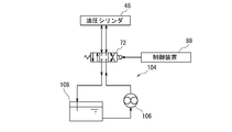
- a working fluid supply system 104 may be further provided to supply oil different from the tooth surface lubricating fluid and the bearing lubricating fluid to the hydraulic cylinder 46 as the working fluid.
- the working fluid supply system 104 has a pump 106 and a tank 108, the inlet of the pump 106 is connected to the outlet of the tank 108, and the outlet of the pump 106 is connected to the inlet of the switching valve 72.
- the inlet of the tank 108 is connected to the outlet of the switching valve 72.
Landscapes
- Engineering & Computer Science (AREA)
- Mechanical Engineering (AREA)
- General Engineering & Computer Science (AREA)
- Applications Or Details Of Rotary Compressors (AREA)
Description
例えば特許文献1が開示する油冷式スクリュー圧縮機はハウジングを有し、ハウジングの内部には、スクリュー室と、スクリュー室の両側に位置するシール室と、シール室を通じてスクリュー室に連なる軸受室とが区画されている。
吸入路は、圧縮室の一端側(吸入側)にて圧縮室と連通するように設けられ、吐出路は、圧縮室の他端側(吐出側)にて圧縮室と連通するように設けられる。
特許文献2には、この構成によれば、腐食成分を含む対象気体を圧縮する場合でも、軸受に対象気体が接触することを防止でき、潤滑油の劣化をさせにくくすることができると記載されている。
軸受潤滑流体のスクリュー室への流入は、軸受潤滑流体と歯面潤滑流体を分けている場合、軸受潤滑流体の供給系統での軸受潤滑流体の保有量の減少を招く。このため、軸受潤滑流体の補充が必要になり、スクリュー圧縮機の運転コストが上昇してしまう。また、軸受潤滑流体のスクリュー室への流入は、歯面潤滑流体の供給系統での流体の保有量の増加を招く。このため、歯面潤滑流体の供給系統での流体の保有量の調整も必要になり、やはりスクリュー圧縮機の運転コストが上昇してしまう。
更に、第2リップシールによって、軸受室からスクリュー室に向かう方向での流体の流れが制限されるので、油冷式スクリュー圧縮機の停止中に分離ガスが供給されていなくても、軸受潤滑流体がスクリュー室に流入することが防止され、もって、軸受潤滑流体の減少が防止される。このため、油冷式スクリュー圧縮機を低コストにて運転することができる。
この構成では、簡単な構成にて、分離ガスの供給圧力を的確に制御することができる。
油冷式スクリュー圧縮機システムは、油冷式スクリュー圧縮機(以下、スクリュー圧縮機ともいう)10と、歯面潤滑流体供給システム12と、軸受潤滑流体供給システム14と、分離ガス供給システム16と、制御システム18とを備えている。
図1及び図2を参照すると、スクリュー圧縮機10は、ハウジング20を有し、ハウジング20の内部には、スクリュー室20a、スクリュー室20aの一端に連なる吸入側シール室20b、吸入側シール室20bを介してスクリュー室20aに連通する吸入側軸受室20c、スクリュー室20aの他端に連なる吐出側シール室20d、及び、吐出側シール室20dを介してスクリュー室20aに連通する吐出側軸受室20eが区画されている。
そして、圧縮室の容積は、吸入口との連通が遮断された直後から、スクリュー部24a,26aの同期回転にともない徐々に減少し、これにより対象気体が圧縮室内で圧縮される。圧縮室が吐出口に連通すると、圧縮された対象気体が吐出口を通じて圧縮室から吐出路20iに吐出される。
また、スラスト軸受として、例えばアンギュラ玉軸受34が、吐出側軸受室20eに配置されている。アンギュラ玉軸受34は、雄スクリューロータ24の吐出側軸部24c及び雌スクリューロータ26の吐出側軸部26cに嵌合され、圧縮室での対象気体の圧縮によって生ずるスラスト荷重(圧縮反力)を受け止める。
なお軸受潤滑流体流路36には、吸入側吐出室20c及び吐出側軸受室20eに軸受潤滑流体を供給するための往路部分と、吸入側吐出室20c及び吐出側軸受室20eから軸受潤滑流体を流出させるための復路部分とがある。
本実施形態では、吸入側軸受ケーシング22cの開口端を閉塞するカバー部材に、圧力流体供給路40が設けられている。
吸入側シール室20b及び吐出側シール室20dには、雄スクリューロータ24及び雌スクリューロータ26の吸入側軸部24b,26b及び吐出側軸部24c,26cの周囲をシールするシール装置50がそれぞれ設けられている。
図4は、吐出側シール室20dに配置された吐出側軸部24c,26cのためのシール装置50の構成を概略的に示している。
第1シールユニットは、スクリュー室20a側に配置され、第2シールユニットは、吐出軸受室20e側に配置されている。
具体的には、第1シールユニットは、非接触型シール部材として、第1ラビリンスシール52を有する。第2シールユニットは、非接触型シール部材として第2ラビリンスシール54を有し、且つ、接触型シール部材としてリップシール56を有する。第1ラビリンスシール52、第2ラビリンスシール54及びリップシール56は、この順序で、スクリュー室20a側から順に配置されている。
回転部材52a,54aは、吐出側軸部24c,26cに嵌合するスリーブ部と、スリーブ部からそれぞれ径方向外側に向かって突出し、互いにスリーブ部の軸線方向に離間した複数の環状の突起とを有する。
第1ラップ部56bは、吐出側軸部24c,26cに近付くほどスクリュー室20aに近付くように湾曲した断面形状を有する。従って、第1ラップ部56bは、スクリュー室20aから吐出側軸受室20eに向かう方向での流体の流れを規制するように配置されている。
第1ラップ部56bよりも吐出軸受室20e側に配置された第2ラップ部56cは、吐出側軸部24c,26cに近付くほど吐出側軸受室20eに近付くように湾曲した断面形状を有する。従って、第2ラップ部56cは、吐出側軸受室20eからスクリュー室20aに向かう流体の流れを規制するように配置されている。
同様に、回転部材52aと回転部材54aが一つの部材によって構成されていてもよい。
更に、回転部材52a,54aは、吐出側軸部24c,26cの外周面に一体に形成されていてもよい。
なお、本実施形態では、図1も併せて参照すると、均圧路60は、雌スクリューロータ26の吐出側軸部26cが挿通された吐出側シール室20dとスクリュー室20aとの間にのみ設けられ、2つの吐出側シール室20dの間は連通路61を介して連通している。
本実施形態では、逆止弁62は、常時開のタイプであり、均圧路60と連通する圧縮室の圧力が吐出側シール室20dの圧力よりも高くなったときだけ閉じる。
吸入側シール室20bに配置されたシール装置50の構成は、吐出側シール室20dに配置されたシール装置50の構成と略同一であるので、同一の構成については同一の符号を付して説明を省略する。
ただし、吸入側シール室20bとスクリュー室20aとの間には、均圧路及び逆止弁は設けられていない。
再び図1を参照すると、歯面潤滑流体供給システム12は、気液分離装置64を有する。気液分離装置64の入口は、例えば導管を通じて、スクリュー圧縮機10の吐出ポート20gに接続されている。気液分離装置64は分離タンク66を有し、分離タンク66の上部には、対象気体と歯面潤滑流体とを分離するフィルタ68が配置されている。分離タンク66の下部には、分離された歯面潤滑流体を一時的に貯留する貯留部70が設けられ、気液分離装置64の入口は、貯留部70とフィルタ68の間にて分離タンク66の内部に連通している。
一方、分離タンク66の底部に、歯面潤滑流体のための液出口が設けられ、液出口は、例えば導管を通じて、スクリュー圧縮機10の歯面潤滑流体流路30に接続されている。スクリュー圧縮機10の運転中、分離タンク66内の圧力は、圧縮された対象気体の圧力、即ち吐出圧力に等しくなり、歯面潤滑流体は、吐出圧力にてスクリュー圧縮機10に供給される。
軸受潤滑流体供給システム14は、大気圧よりも高圧にて軸受潤滑流体を貯留可能な貯留タンク74を有する。貯留タンク74の出口は、例えば導管を通じて、軸受潤滑流体流路36の往路部分に接続されている。なお、導管の途中には、貯留タンク74からスクリュー圧縮機10に向かう方向での軸受潤滑流体の流れを生成するためのポンプ76、及び、軸受潤滑流体を冷却するための熱交換器78が介装されている。
分離ガス供給システム16は、スクリュー圧縮機10の運転中、スクリュー圧縮機10に分離ガスを供給するように構成されている。分離ガスとしては、例えば、窒素等の不活性ガスを用いることができる。
制御システム18は、制御装置88と複数のセンサとからなる。制御装置88は、例えば、中央演算処理装置、メモリ、外部記憶装置、及び、入出力装置等からなるコンピュータによって構成される。
例えば、制御装置88は、動力源を制御してスクリュー圧縮機10への動力の供給量を調整し、図示しないポンプ等を制御して熱交換器への冷媒の供給量を調整し、ポンプ76を制御して軸受潤滑流体の供給量を調整し、更に、切替弁72を制御してスクリュー圧縮機10の容量を調整する
なお、この範囲内であれば、分離ガス供給圧力は吐出圧力よりも低く抑えられる。
本実施形態では、第2リップ部56cの吸入側軸受室20c側や吐出側軸受室20e側に作用する圧力が、吸入側シール室20bや吐出側シール室20dにおける第1ラビリンスシール52よりもスクリュー室20a側の領域の圧力と略等しくなるように、制御装置88は戻り圧力を制御する。例えば、制御装置88は、吸入圧力が0.1MPa~0.6MPaの範囲内にあるときに、軸受潤滑流体の戻り圧力が、0.01MPa~0.7MPa程度になるように制御を行う。
一方、スクリュー圧縮機100は、吸入側及び吐出側シールケーシング22b,22dを有していない点において、スクリュー圧縮機10と異なっている。また、これに伴い、スクリュー圧縮機10とスクリュー圧縮機100とでは、雄雌のスクリューロータ24,26の吸入側軸部24b,26b及び吐出側軸部24c,26cの長さが異なっている。
例えば、図9に示したように、油圧シリンダ46の作動流体として、軸受潤滑流体を用いてもよい。この場合、切替弁72の入口は、導管を介して熱交換器78に接続され、切替弁72の出口は、導管を介して貯留タンク74に接続される。
12 歯面潤滑流体供給システム
14 軸受潤滑流体供給システム
16 分離ガス供給システム
18 制御システム
20 ハウジング
20a スクリュー室
20b 吸入側シール室(シール室)
20c 吸入側軸受室(軸受室)
20d 吐出側シール室(シール室)
20e 吐出側軸受室(軸受室)
24 雄スクリューロータ
26 雌スクリューロータ
24a,26a スクリュー部
24b,26b 吸入側軸部
24c,26c 吐出側軸部
30 歯面潤滑流体流路
50 シール装置
52 第1ラビリンスシール
54 第2ラビリンスシール
56 リップシール(第1リップシール,第2リップシール)
58 分離ガス供給隙間
59 分離ガス供給路
60 均圧路
62 逆止弁
64 気液分離装置
74 貯留タンク
80,84,86 制御弁
88 制御装置
90a 吸入圧力センサ
90b 吐出圧力センサ
90c 1次圧力センサ
90d 2次圧力センサ
90e 戻り圧力センサ
Claims (11)
- 油冷式スクリュー圧縮機と、該油冷式スクリュー圧縮機に歯面潤滑流体を供給するための歯面潤滑流体供給システムと、前記油冷式スクリュー圧縮機に、前記歯面潤滑流体とは別に軸受潤滑流体を供給するための軸受潤滑流体供給システムと、前記油冷式スクリュー圧縮機に、該油冷式スクリュー圧縮機によって圧縮される対象気体とは異なる分離ガスを供給する分離ガス供給システムと、を備え、
前記油冷式スクリュー圧縮機は、
スクリュー室、該スクリュー室の両側に位置するシール室、該シール室を介して前記スクリュー室に連通する軸受室、前記スクリュー室に前記歯面潤滑流体を供給するための歯面潤滑流体流路、及び、前記軸受室に前記軸受潤滑流体を供給するための軸受潤滑流体流路が内部に規定されたハウジングと、
前記スクリュー室に配置されて圧縮室を形成するスクリュー部、並びに、該スクリュー部の両端から同軸に延びて前記シール室及び前記軸受室に配置される軸部をそれぞれ有する、雄雌のスクリューロータと、
前記軸受室に配置され、対応する前記軸部を回転可能に支持する複数の軸受と、
前記シール室に配置され、対応する前記軸部の周囲をシールするシール装置と、を有し、
前記シール装置は、
前記シール室の前記スクリュー室側に配置される第1シールユニットと、
前記シール室の前記軸受室側に配置され、前記第1シールユニットとの間に分離ガス供給隙間を規定する第2シールユニットとを有し、
前記シール室は、前記圧縮室の吐出側に位置する吐出側シール室と、前記圧縮室の吸入側に位置する吸入側シール室とからなり、
前記ハウジングの内部には、
前記歯面潤滑流体流路及び前記軸受潤滑流体流路とは別に、前記分離ガス供給隙間に前記分離ガスを供給するための分離ガス供給路が規定されるとともに、前記吐出側シール室における前記第1シールユニットよりも前記スクリュー室側の領域と前記油冷式スクリュー圧縮機に吸入される前記対象気体の吸入圧力よりも高圧状態で且つ前記油冷式スクリュー圧縮機から吐出される前記対象気体の吐出圧力よりも低圧状態の前記圧縮室とを連通するように構成された均圧路が規定され、
前記均圧路に、前記吐出側シール室から前記スクリュー室へ向かう方向での流体の流れを制限する逆止弁が配置されている
ことを特徴とする油冷式スクリュー圧縮機システム。 - 前記ハウジングは、
前記スクリュー室を規定するスクリューケーシングと、
前記スクリューケーシングに分離可能に連結され、前記シール室及び前記均圧路を規定するシールケーシングと、
前記シールケーシングを介して前記スクリューケーシングに分離可能に連結され、前記軸受室を規定する軸受ケーシングと
からなることを特徴とする請求項1に記載の油冷式スクリュー圧縮機システム。 - 前記第1シールユニットは、第1ラビリンスシールを有し、
前記第2シールユニットは、前記分離ガス供給隙間から前記軸受室に向かって順に、第2ラビリンスシール、第1リップシール、及び、第2リップシールを有し、
前記第1リップシールは、前記スクリュー室から前記軸受室に向かう方向での流体の流れを阻止するように配置され、
前記第2リップシールは、前記軸受室から前記スクリュー室に向かう方向での流体の流れを阻止するように配置されている
ことを特徴とする請求項2に記載の油冷式スクリュー圧縮機システム。 - 前記油冷式スクリュー圧縮機に供給される前記分離ガスの供給圧力を制御する制御システムを更に備え、
前記制御システムは、前記油冷式スクリュー圧縮機に供給される前記分離ガスの供給圧力が前記吸入圧力よりも高く、且つ、前記吐出圧力よりも低くなるように、前記分離ガスの供給圧力を制御するように構成されている
ことを特徴とする請求項1に記載の油冷式スクリュー圧縮機システム。 - 前記制御システムは、前記油冷式スクリュー圧縮機から流出する前記軸受潤滑流体の戻り圧力が前記吸入圧力以上であって、前記分離ガスの供給圧力よりも低くなるように、前記軸受潤滑流体の供給圧力を制御するように構成されていることを特徴とする請求項4に記載の油冷式スクリュー圧縮機システム。
- 前記軸受潤滑流体供給システムは、前記吸入圧力よりも高い貯留圧力にて前記軸受潤滑流体を貯留する貯留タンクを有し、
前記貯留タンク内の圧力を前記貯留圧力まで高めるための加圧ガスとして、前記分離ガスと同種のガスが用いられる
ことを特徴とする請求項5に記載の油冷式スクリュー圧縮機システム。 - 前記制御システムは、
前記吸入圧力を検出する吸入圧力センサと、
前記分離ガスの供給圧力を調整可能な制御弁と、
前記吸入圧力センサによる検出結果に応じて、前記制御弁を操作する制御装置と
を有することを特徴とする請求項4に記載の油冷式スクリュー圧縮機システム。 - 前記油冷式スクリュー圧縮機は容量制御装置を更に備え、
前記歯面潤滑流体供給システムは、前記容量制御装置に対し、前記歯面潤滑流体の一部を作動流体として供給するように構成されている
ことを特徴とする請求項1に記載の油冷式スクリュー圧縮機システム。 - スクリュー室、該スクリュー室の両側に位置するシール室、該シール室を介して前記スクリュー室に連通する軸受室、前記スクリュー室に歯面潤滑流体を供給するための歯面潤滑流体流路、及び、前記歯面潤滑流体流路とは別に前記軸受室に軸受潤滑流体を供給するための軸受潤滑流体流路が内部に規定されたハウジングと、
前記スクリュー室に配置されるスクリュー部、該スクリュー部の両端から同軸に延び、前記シール室及び前記軸受室に配置される軸部をそれぞれ有する雄雌のスクリューロータと、
前記軸受室に配置され、対応する前記軸部を回転可能に支持する複数の軸受と、
前記シール室に配置され、対応する前記軸部の周囲をシールするシール装置とを備え、
前記シール装置は、
前記シール室の前記スクリュー室側に配置される第1シールユニットと、
前記シール室の前記軸受室側に配置され、前記第1シールユニットとの間に分離ガス供給隙間を規定する第2シールユニットとを有し、
前記シール室は、前記圧縮室の吐出側に位置する吐出側シール室と、前記圧縮室の吸入側に位置する吸入側シール室とからなり、
前記ハウジングの内部には、
前記歯面潤滑流体流路及び前記軸受潤滑流体流路とは別に、前記分離ガス供給隙間に前記分離ガスを供給するための分離ガス供給路が規定されるとともに、前記吐出側シール室における前記第1シールユニットよりも前記スクリュー室側の領域と前記油冷式スクリュー圧縮機に吸入される前記対象気体の吸入圧力よりも高圧状態で前記油冷式スクリュー圧縮機から吐出される前記対象気体の吐出圧力よりも低圧状態の前記圧縮室とを連通するように構成された均圧路が規定され、
前記均圧路に、前記スクリュー室から前記吐出側シール室へ向かう方向での流体の流れを制限する逆止弁が配置されている
ことを特徴とする油冷式スクリュー圧縮機。 - 前記ハウジングは、
前記スクリュー室を規定するスクリューケーシングと、
前記スクリューケーシングに分離可能に連結され、前記シール室及び前記均圧路を規定するシールケーシングと、
前記シールケーシングを介して前記スクリューケーシングに分離可能に連結され、前記軸受室を規定する軸受ケーシングと
からなることを特徴とする請求項9に記載の油冷式スクリュー圧縮機。 - 前記第1シールユニットは、第1ラビリンスシールを有し、
前記第2シールユニットは、前記分離ガス供給隙間から前記軸受室に向かって順に、第2ラビリンスシール、第1リップシール、及び、第2リップシールを有し、
前記第1リップシールは、前記スクリュー室から前記軸受室に向かう方向での流体の流れを阻止するように配置され、
前記第2リップシールは、前記軸受室から前記スクリュー室に向かう方向での流体の流れを阻止するように配置されている
ことを特徴とする請求項10に記載の油冷式スクリュー圧縮機。
Priority Applications (5)
| Application Number | Priority Date | Filing Date | Title |
|---|---|---|---|
| DK12884596.3T DK2896834T3 (en) | 2012-09-14 | 2012-09-14 | OIL COOLED SCREW COMPRESSOR SYSTEM AND OIL COOLED SCREW COMPRESSOR |
| EP12884596.3A EP2896834B1 (en) | 2012-09-14 | 2012-09-14 | Oil-cooled screw compressor system and oil-cooled screw compressor |
| US14/428,099 US9568001B2 (en) | 2012-09-14 | 2012-09-14 | Oil-cooled screw compressor system and oil-cooled screw compressor |
| PCT/JP2012/073622 WO2014041680A1 (ja) | 2012-09-14 | 2012-09-14 | 油冷式スクリュー圧縮機システム及び油冷式スクリュー圧縮機 |
| JP2014535323A JP6041449B2 (ja) | 2012-09-14 | 2012-09-14 | 油冷式スクリュー圧縮機システム及び油冷式スクリュー圧縮機 |
Applications Claiming Priority (1)
| Application Number | Priority Date | Filing Date | Title |
|---|---|---|---|
| PCT/JP2012/073622 WO2014041680A1 (ja) | 2012-09-14 | 2012-09-14 | 油冷式スクリュー圧縮機システム及び油冷式スクリュー圧縮機 |
Publications (1)
| Publication Number | Publication Date |
|---|---|
| WO2014041680A1 true WO2014041680A1 (ja) | 2014-03-20 |
Family
ID=50277833
Family Applications (1)
| Application Number | Title | Priority Date | Filing Date |
|---|---|---|---|
| PCT/JP2012/073622 Ceased WO2014041680A1 (ja) | 2012-09-14 | 2012-09-14 | 油冷式スクリュー圧縮機システム及び油冷式スクリュー圧縮機 |
Country Status (5)
| Country | Link |
|---|---|
| US (1) | US9568001B2 (ja) |
| EP (1) | EP2896834B1 (ja) |
| JP (1) | JP6041449B2 (ja) |
| DK (1) | DK2896834T3 (ja) |
| WO (1) | WO2014041680A1 (ja) |
Cited By (4)
| Publication number | Priority date | Publication date | Assignee | Title |
|---|---|---|---|---|
| CN106257056A (zh) * | 2015-06-16 | 2016-12-28 | 曼柴油机和涡轮机欧洲股份公司 | 螺杆机器及用于操作其的方法 |
| JP2017137794A (ja) * | 2016-02-02 | 2017-08-10 | 株式会社神戸製鋼所 | 圧縮機 |
| EP3249226A4 (en) * | 2015-02-12 | 2017-11-29 | Mayekawa Mfg. Co., Ltd. | Oil-flooded screw compressor system and method for modifying same |
| JP2019044737A (ja) * | 2017-09-06 | 2019-03-22 | 株式会社神戸製鋼所 | 圧縮装置 |
Families Citing this family (20)
| Publication number | Priority date | Publication date | Assignee | Title |
|---|---|---|---|---|
| WO2013049438A2 (en) | 2011-09-30 | 2013-04-04 | Eaton Corporation | Supercharger assembly with independent superchargers and motor/generator |
| WO2013049439A2 (en) * | 2011-09-30 | 2013-04-04 | Eaton Corporation | Supercharger assembly with two rotor sets |
| US9534531B2 (en) | 2011-09-30 | 2017-01-03 | Eaton Corporation | Supercharger assembly for regeneration of throttling losses and method of control |
| JP2015514624A (ja) | 2012-03-29 | 2015-05-21 | イートン コーポレーションEaton Corporation | 可変速度式ハイブリッド電気スーパーチャージャーアセンブリを用いた電気エネルギの生成 |
| CN105209731A (zh) | 2013-03-12 | 2015-12-30 | 伊顿公司 | 用于高效车辆操作的可变速混合电子增压器组件的适配充电状态的调节和控制 |
| JP6686144B2 (ja) * | 2015-12-11 | 2020-04-22 | アトラス コプコ エアーパワー, ナームローゼ フェンノートシャップATLAS COPCO AIRPOWER, naamloze vennootschap | 圧縮機の液体噴射を調整する方法、液体噴射式圧縮機及び液体噴射式圧縮機要素 |
| CA3006624C (en) | 2015-12-11 | 2020-07-21 | Atlas Copco Airpower, Naamloze Vennootschap | Method for controlling the liquid injection of a compressor device or expander device, a liquid-injected compressor device or expander device and a liquid-injected compressor element or expander element |
| BE1023714B1 (nl) * | 2015-12-11 | 2017-06-26 | Atlas Copco Airpower Naamloze Vennootschap | Werkwijze voor het regelen van de vloeistofinjectie van een compressor- of expanderinrichting, een vloeistofgeïnjecteerde compressor- of expanderinrichting en een vloeistofgeïnjecteerd compressor- of expanderelement |
| BE1023673B1 (nl) * | 2015-12-11 | 2017-06-12 | Atlas Copco Airpower Naamloze Vennootschap | Werkwijze voor het regelen van de vloeistofinjectie van een compressorinrichting, een vloeistofgeïnjecteerde compressorinrichting en een vloeistofgeïnjecteerd compressorelement |
| WO2018165455A1 (en) | 2017-03-09 | 2018-09-13 | Johnson Controls Technology Company | Back to back bearing sealing systems |
| CN108757453A (zh) * | 2018-08-23 | 2018-11-06 | 中山市捷科能机电科技有限公司 | 一种喷水双螺杆压缩机 |
| CN108843569A (zh) * | 2018-08-23 | 2018-11-20 | 中山市捷科能机电科技有限公司 | 喷水双螺杆压缩机 |
| JP2020076450A (ja) * | 2018-11-07 | 2020-05-21 | 本田技研工業株式会社 | シール構造 |
| CN109595169B (zh) * | 2019-01-14 | 2019-12-13 | 冰轮环境技术股份有限公司 | 无油螺杆压缩机密封机构及控制方法 |
| US11867180B2 (en) | 2019-03-22 | 2024-01-09 | Copeland Industrial Lp | Seal assembly for high pressure single screw compressor |
| US11448220B2 (en) * | 2019-09-27 | 2022-09-20 | Ingersoll-Rand Industrial U.S., Inc. | Airend having a lubricant flow valve and controller |
| DE102021116925A1 (de) * | 2021-06-30 | 2023-01-05 | Kaeser Kompressoren Se | Trockenverdichtender Verdichter und Verfahren zur Ölabscheidung für einen trockenverdichtenden Verdichter |
| CN114704462A (zh) * | 2022-05-18 | 2022-07-05 | 肖和均 | 一种双润滑油路工作的螺杆压缩机组 |
| CN115507025B (zh) * | 2022-10-18 | 2024-02-27 | 西安交通大学 | 一种高转子轴向均温性双螺杆压缩机 |
| CN115929635B (zh) * | 2022-11-29 | 2024-03-15 | 广东标顶技术股份有限公司 | 一种风源系统的螺杆空气压缩组件 |
Citations (4)
| Publication number | Priority date | Publication date | Assignee | Title |
|---|---|---|---|---|
| JPH10501862A (ja) * | 1994-06-21 | 1998-02-17 | スベンスカ ロツタア マスキナア アクチボラグ | 液体循環システムを備えた回転式容積圧縮機 |
| JP4365443B1 (ja) | 2008-07-29 | 2009-11-18 | 株式会社神戸製鋼所 | 無給油式スクリュ圧縮機 |
| JP4431184B2 (ja) | 2008-06-13 | 2010-03-10 | 株式会社神戸製鋼所 | スクリュ圧縮装置 |
| JP2012149631A (ja) * | 2010-12-27 | 2012-08-09 | Kobe Steel Ltd | 水噴射式スクリュ流体機械 |
Family Cites Families (6)
| Publication number | Priority date | Publication date | Assignee | Title |
|---|---|---|---|---|
| GB1484994A (en) | 1973-09-03 | 1977-09-08 | Svenska Rotor Maskiner Ab | Shaft seal system for screw compressors |
| DE2948992A1 (de) * | 1979-12-05 | 1981-06-11 | Karl Prof.Dr.-Ing. 3000 Hannover Bammert | Rotorverdichter, insbesondere schraubenrotorverdichter, mit schmiermittelzufuhr zu und schmiermitteldrainage von den lagern |
| US5228298A (en) * | 1992-04-16 | 1993-07-20 | Praxair Technology, Inc. | Cryogenic rectification system with helical dry screw expander |
| BE1010915A3 (nl) * | 1997-02-12 | 1999-03-02 | Atlas Copco Airpower Nv | Inrichting voor het afdichten van een rotoras en schroefcompressor voorzien van dergelijke inrichting. |
| SE510066C2 (sv) * | 1997-08-25 | 1999-04-12 | Svenska Rotor Maskiner Ab | Oljefri skruvrotormaskin vilkens lager smörjes med en vattenhaltig vätska |
| FR2920207B1 (fr) * | 2007-08-23 | 2009-10-09 | Alcatel Lucent Sas | Pompe a vide de type seche comportant un dispositif d'etancheite aux fluides lubrifiants et elements centrifugeur equipant un tel dispositif |
-
2012
- 2012-09-14 EP EP12884596.3A patent/EP2896834B1/en active Active
- 2012-09-14 JP JP2014535323A patent/JP6041449B2/ja active Active
- 2012-09-14 WO PCT/JP2012/073622 patent/WO2014041680A1/ja not_active Ceased
- 2012-09-14 US US14/428,099 patent/US9568001B2/en active Active
- 2012-09-14 DK DK12884596.3T patent/DK2896834T3/en active
Patent Citations (4)
| Publication number | Priority date | Publication date | Assignee | Title |
|---|---|---|---|---|
| JPH10501862A (ja) * | 1994-06-21 | 1998-02-17 | スベンスカ ロツタア マスキナア アクチボラグ | 液体循環システムを備えた回転式容積圧縮機 |
| JP4431184B2 (ja) | 2008-06-13 | 2010-03-10 | 株式会社神戸製鋼所 | スクリュ圧縮装置 |
| JP4365443B1 (ja) | 2008-07-29 | 2009-11-18 | 株式会社神戸製鋼所 | 無給油式スクリュ圧縮機 |
| JP2012149631A (ja) * | 2010-12-27 | 2012-08-09 | Kobe Steel Ltd | 水噴射式スクリュ流体機械 |
Cited By (10)
| Publication number | Priority date | Publication date | Assignee | Title |
|---|---|---|---|---|
| EP3249226A4 (en) * | 2015-02-12 | 2017-11-29 | Mayekawa Mfg. Co., Ltd. | Oil-flooded screw compressor system and method for modifying same |
| AU2015382226B2 (en) * | 2015-02-12 | 2019-03-28 | Mayekawa Mfg. Co., Ltd. | Oil-cooled screw compressor system and method for modifying same |
| US10662947B2 (en) | 2015-02-12 | 2020-05-26 | Mayekawa Mfg. Co., Ltd. | Oil-flooded screw compressor system and method for modifying the same |
| CN106257056A (zh) * | 2015-06-16 | 2016-12-28 | 曼柴油机和涡轮机欧洲股份公司 | 螺杆机器及用于操作其的方法 |
| JP2017008934A (ja) * | 2015-06-16 | 2017-01-12 | マン・ディーゼル・アンド・ターボ・エスイー | スクリュー機械及びスクリュー機械の運転方法 |
| GB2541278A (en) * | 2015-06-16 | 2017-02-15 | Man Diesel & Turbo Se | Screw machine and method for operating the same |
| US10060435B2 (en) | 2015-06-16 | 2018-08-28 | Man Energy Solutions Se | Screw machine and method for operating the same |
| GB2541278B (en) * | 2015-06-16 | 2019-11-13 | Man Energy Solutions Se | Screw machine and method for operating the same |
| JP2017137794A (ja) * | 2016-02-02 | 2017-08-10 | 株式会社神戸製鋼所 | 圧縮機 |
| JP2019044737A (ja) * | 2017-09-06 | 2019-03-22 | 株式会社神戸製鋼所 | 圧縮装置 |
Also Published As
| Publication number | Publication date |
|---|---|
| JPWO2014041680A1 (ja) | 2016-08-12 |
| EP2896834B1 (en) | 2017-10-25 |
| EP2896834A4 (en) | 2016-08-17 |
| EP2896834A1 (en) | 2015-07-22 |
| DK2896834T3 (en) | 2017-12-04 |
| US20150260187A1 (en) | 2015-09-17 |
| US9568001B2 (en) | 2017-02-14 |
| JP6041449B2 (ja) | 2016-12-07 |
Similar Documents
| Publication | Publication Date | Title |
|---|---|---|
| JP6041449B2 (ja) | 油冷式スクリュー圧縮機システム及び油冷式スクリュー圧縮機 | |
| US7815423B2 (en) | Compressor with fluid injection system | |
| CN103189650B (zh) | 涡旋式压缩机 | |
| CN102678546B (zh) | 涡旋压缩机 | |
| CN107208634A (zh) | 涡旋式压缩机 | |
| CN101297117A (zh) | 涡旋压缩机 | |
| US10330098B2 (en) | Scroll compressor with controlled pressing force | |
| EP3073117B1 (en) | Scroll compressor | |
| US20200003211A1 (en) | Screw compressor | |
| JP2013139714A (ja) | スクロール圧縮機 | |
| CN101258327A (zh) | 具有流体喷射系统的压缩机 | |
| JP5278228B2 (ja) | スクロール圧縮機 | |
| JP2012241680A (ja) | スクロール圧縮機 | |
| JP5180698B2 (ja) | スクロール型流体機械 | |
| JP4604968B2 (ja) | スクロール圧縮機 | |
| JP4062443B2 (ja) | スクリュー圧縮装置 | |
| JP2005163745A (ja) | スクロール圧縮機 | |
| JP6599099B2 (ja) | スクロール流体機械 | |
| JP2005171952A (ja) | スクロール圧縮機 | |
| JP2006226246A (ja) | スクロール圧縮機 | |
| JP2015183585A (ja) | スクロール型圧縮機 | |
| JP2024091916A (ja) | スクロール圧縮機 | |
| JP2005163573A (ja) | スクロール圧縮機 | |
| JP2005146902A (ja) | スクロール圧縮機 | |
| JP2006291763A (ja) | スクロール圧縮機 |
Legal Events
| Date | Code | Title | Description |
|---|---|---|---|
| 121 | Ep: the epo has been informed by wipo that ep was designated in this application |
Ref document number: 12884596 Country of ref document: EP Kind code of ref document: A1 |
|
| ENP | Entry into the national phase |
Ref document number: 2014535323 Country of ref document: JP Kind code of ref document: A |
|
| REEP | Request for entry into the european phase |
Ref document number: 2012884596 Country of ref document: EP |
|
| WWE | Wipo information: entry into national phase |
Ref document number: 14428099 Country of ref document: US |
|
| NENP | Non-entry into the national phase |
Ref country code: DE |