WO2014038252A1 - ワーク固定装置 - Google Patents
ワーク固定装置 Download PDFInfo
- Publication number
- WO2014038252A1 WO2014038252A1 PCT/JP2013/064217 JP2013064217W WO2014038252A1 WO 2014038252 A1 WO2014038252 A1 WO 2014038252A1 JP 2013064217 W JP2013064217 W JP 2013064217W WO 2014038252 A1 WO2014038252 A1 WO 2014038252A1
- Authority
- WO
- WIPO (PCT)
- Prior art keywords
- work
- cylinder unit
- oil cylinder
- workpiece
- support portion
- Prior art date
- Legal status (The legal status is an assumption and is not a legal conclusion. Google has not performed a legal analysis and makes no representation as to the accuracy of the status listed.)
- Ceased
Links
Images



Classifications
-
- B—PERFORMING OPERATIONS; TRANSPORTING
- B23—MACHINE TOOLS; METAL-WORKING NOT OTHERWISE PROVIDED FOR
- B23Q—DETAILS, COMPONENTS, OR ACCESSORIES FOR MACHINE TOOLS, e.g. ARRANGEMENTS FOR COPYING OR CONTROLLING; MACHINE TOOLS IN GENERAL CHARACTERISED BY THE CONSTRUCTION OF PARTICULAR DETAILS OR COMPONENTS; COMBINATIONS OR ASSOCIATIONS OF METAL-WORKING MACHINES, NOT DIRECTED TO A PARTICULAR RESULT
- B23Q3/00—Devices holding, supporting, or positioning work or tools, of a kind normally removable from the machine
- B23Q3/02—Devices holding, supporting, or positioning work or tools, of a kind normally removable from the machine for mounting on a work-table, tool-slide, or analogous part
- B23Q3/06—Work-clamping means
- B23Q3/066—Bench vices
Definitions
- the present invention relates to an apparatus for fixing a work such as an engine of a motorcycle.
- the engine Since the weight of the engine is the largest for assembling a motorcycle, the engine is fixed to a fixing device, and a frame or the like is assembled to the fixed engine.
- a device for fixing a work such as such an engine those disclosed in Patent Document 1 and Patent Document 2 are known.
- Patent Document 1 discloses a receiving jig having a plurality of pins which are vertically movable and whose lower part is supported by a biasing member.
- this receiving jig when the work is mounted on the upper portion of the pins, each pin is pushed down in a state conforming to the shape of the lower surface of the work, and when the stopper plate is lowered in that state, the retainer pressed downward by the pressing member is also As it descends, the steel ball engages with the tapered surface of the cylindrical member and protrudes inward, and enters into the concave groove of the pin outer surface to lock it.
- Patent Document 2 discloses a flexible fixing jig.
- This flexible fixing jig is filled with steel balls and a thermoplastic resin in a metal container.
- the thermoplastic resin is preheated to about 150 ° C., and the steel ball is in a viscous state at the gap.
- the work is moved by pressing the work, the pin is inserted according to the shape of the work, and the thermoplastic resin is cooled to room temperature in this state, the steel balls are bonded by the thermoplastic resin and the work is fixed on the pin.
- thermoplastic resin in order to make the thermoplastic resin have fluidity, it is necessary to heat the whole to 150 ° C. or higher and then to cool it when fixing. That is, it is necessary to repeat heating and cooling, which not only complicates the structure of the apparatus but also complicates the work process.
- the work fixing device is provided with a support portion for supporting a work such as an engine from below, and the support portion moves up and down according to the shape of the work and locks at a predetermined position.
- Possible oil cylinder unit Possible oil cylinder unit.
- the support portion In order to be able to cope with a workpiece having a complicated shape and to be able to be generalized further, it is preferable to divide the support portion into a plurality and provide the oil cylinder unit for each of the divided support portions. Further, in order to prevent the work from being damaged and to prevent rattling when the work is placed, it is preferable to attach a work receiving member made of a deformable material such as urethane resin to the end of the rod of the oil cylinder unit.
- a resilient member such as a spring is provided around the rod of the oil cylinder unit to urge the work receiving member upward so that the oil cylinder unit is not rapidly compressed and received an impact when the work is placed. Is preferred.
- the work fixing device According to the work fixing device according to the present invention, it is possible to reliably fix a plurality of types of works without using a device having a complicated structure such as a heavy engine such as an engine having a heavy weight and a complicated shape. Therefore, by applying to an assembly line of a motorcycle, etc., loss reduction of jig replacement and cost reduction of jig preparation can be greatly improved.
- the workpiece fixing device is provided on the base 1 with clamp arms 2 and 3, a tilt receiving member 4 and a workpiece support 5.
- the clamp arm 2 can be moved back and forth (left and right direction in FIG. 1) along the rail 22 by a screw mechanism 21 rotated by a handle 20 and a work pressing pad advanced and retracted by a screw mechanism 24 rotated by a handle 23 at the upper end 25 is attached.
- the clamp arm 3 can also be advanced and retracted along the rail 31 by operating the handle 30, and a work pressing pad 32 is attached to the tip.
- the work pressing pad 32 protrudes to the work W side by tilting the lever 33, and strongly fixes the work W.
- the clamp arm 3 is rotatably supported by the support frame 35 via a shaft 34.
- the clamp arm 3 is tilted about the shaft 34 until it hits the tilt receiving member 4 and the carry in / out space is expanded I am improving work efficiency.
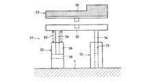
- the work supporting portion 5 is composed of three divided supporting portions 51.
- Each divided support portion 51 is composed of an oil cylinder unit 52, a guide member 72 and a work receiving member 53.
- Each divided support portion 51 is independent, and for each divided support portion 51, an oil cylinder unit 52, a guide member 72 and One work receiving member 53 is provided.
- the positions of the oil cylinder unit 52 and the guide member 72 of the central divided support portion 51 are opposite to the positions of the oil cylinder unit 52 and the guide member 72 of the adjacent divided support portion 51, three in plan view.
- the oil cylinder unit 52 of the divided support portion 51 forms a triangle to achieve stabilization.
- the work receiving member 53 is composed of a plate 55 which is bridged between the upper ends of the piston rods 54 of the two oil cylinder units 52 and a receiving body 56 engaged with the plate 55 in a concavo-convex manner.
- a plate 55 which is bridged between the upper ends of the piston rods 54 of the two oil cylinder units 52 and a receiving body 56 engaged with the plate 55 in a concavo-convex manner.
- the inside of the cylinder 58 is divided into an upper chamber 59a and a lower chamber 59b by a piston 57 attached to a piston rod 54, and the upper chamber 59a and the lower chamber 59b are communicated with each other by a pipe 60.
- a pipe 60 Is provided with an on / off valve 61.
- the lower chamber 59b is provided with an accumulator 62 for receiving oil corresponding to the volume of the intrusion of the piston rod 54.
- the accumulator 62 can also be disposed in the cylinder.
- a guide hole 73 is formed in the vertical direction in the guide member 72, and a rod 74 attached to the plate 55 is slidably engaged with the guide hole 73.
- a spring 63 is provided between the upper surface of the cylinder 58 and the plate 55 so that when the work W is placed on the work receiving member 53, the piston 57 is gradually lowered.
- the spring 63 may be provided not only between the upper surface of the cylinder 58 and the plate 55 but also between the upper surface of the guide member 72 and the plate 55 as shown in FIG. It may be provided only between 55.
- the work W is set on the work support 5 with the on / off valve 61 open. Then, the state shown in FIG. 3A is shifted to the state shown in FIG. That is, the workpiece receiving member 53, the piston rod 54 and the piston 57 move downward for each divided support portion 51 according to the shape and weight of the workpiece W, and the oil in the lower chamber 59b moves to the upper chamber 59a.
- the movement of the piston 57 is performed slowly by the step force of the spring 63 and the resistance caused by the flow of oil. Then, when the piston 57 is lowered to a predetermined position, the weight of the work W and the step force of the spring 63 are balanced, and the downward movement of the piston 57 is stopped. Therefore, the on / off valve 61 is closed. As a result, the oil cylinder unit 52 is locked, and the shape of the workpiece support 5 does not change any more.
- the work fixing jig according to the present invention can be used, for example, in a process of fixing an engine and assembling other members to an engine fixed sequentially in an assembly line of a motorcycle.
- Work clamp Pads 30 Handles 31 Rails 32 Workpiece pressing pads 33 Lever 34 Axis 35 Support frame 51 Split support portion 52 Oil cylinder unit 53 Work receiving member 54 Piston Rod, 55: Plate, 56: Receiving body, 57: Piston, 58: Cylinder, 59a: Upper chamber of cylinder, 59b: Lower chamber of cylinder, 60: Piping, 61: On-off valve, 62: Accumulator, 63: Spring , 72: guide member, 73: guide hole, 74: rod, W: work.
Landscapes
- Engineering & Computer Science (AREA)
- Mechanical Engineering (AREA)
- Automatic Assembly (AREA)
- Jigs For Machine Tools (AREA)
Description
本発明は、自動二輪車のエンジン等のワークを固定する装置に関する。
自動二輪車を組立てるには、エンジンの重量が最も重いので、このエンジンを固定装置に固定し、固定したエンジンにフレーム等を組み付けるようにしている。このようなエンジン等のワークを固定する装置として特許文献1及び特許文献2に開示されるものが知られている。
特許文献1には、昇降自在で且つ下方部が付勢部材で支持される複数のピンを備えた受け治具が開示されている。この受け治具は、ピンの上部にワークを搭載すると、ワーク下面の形状に倣った状態で各ピンが押し下げられ、その状態でストッパプレートを降下させると、押圧部材で下方に押圧されるリテーナも降下し、鋼球が筒状部材のテーパ面に係合して内方に突出し、ピン外面の凹溝内に入り込んでロックする構造になっている。
特許文献2には、フレキシブル固定治具が開示されている。このフレキシブル固定治具は金属製容器内に鋼球と熱可塑性樹脂を充填している。そしてワークを支持するピンを上方から鋼球と点接触した状態で押し込むと、熱可塑性樹脂は予め約150℃に加熱されていて、鋼球の隙間で粘性を持った状態であるため、鋼球はワークの押圧によって移動し、ワークの形状に応じてピンが差し込まれこの状態において熱可塑性樹脂を常温に冷却すると、鋼球は熱可塑性樹脂によって接着されてワークはピン上に固定される。
特許文献1に開示される装置にあっては、多数のピンが必要で、しかも各ピンごとにリテーナ、ストッパプレート、スプリング、スチールボール等を組み込まなければならず、構造が複雑となりコストアップになってしまう。
特許文献2に開示される装置にあっては、熱可塑性樹脂に流動性を持たせるために全体を150℃以上に加熱し、この後、固定する際に冷却する必要がある。即ち、加熱と冷却を繰り返す必要があり装置の構造が複雑になるだけでなく、作業工程も面倒になる。
上記課題を解決するため本発明に係るワーク固定装置には、エンジン等のワークを下方から支持する支持部が設けられ、この支持部はワークの形状に倣って昇降動するとともに所定の位置でロック可能なオイルシリンダユニットを備える。
複雑形状のワークにも対応でき、さらに汎用化できるようにするには、前記支持部を複数に分割し、各分割支持部ごとに前記オイルシリンダユニットを設けることが好ましい。また、ワークを載置した場合にワークを傷つけることなく且つガタつきをなくすためには、オイルシリンダユニットのロッド先端はウレタン樹脂などの変形可能な材料からなるワーク受け部材を取り付けることが好ましい。
また、ワークを載置した際に、急激にオイルシリンダユニットが縮んで衝撃を受けないように、オイルシリンダユニットのロッドの周囲にワーク受け部材を上方に付勢するスプリングなどの弾発部材を設けることが好ましい。
本発明に係るワーク固定装置によれば、エンジン等の重量が重く形状が複雑なワークを、複雑な構造の装置を用いることなく、複数種類のワークを確実に固定することができる。したがって、自動二輪車の組立てラインなどに適用することで、治具交換のロス削減、治具作成のコスト削減が大幅に向上する。
以下に本発明の実施例を添付図面に基づいて説明する。
ワーク固定装置は基台1上に、クランプアーム2,3、傾動受け部材4及びワーク支持部5が設けられている。
ワーク固定装置は基台1上に、クランプアーム2,3、傾動受け部材4及びワーク支持部5が設けられている。
クランプアーム2はハンドル20によって回転するネジ機構21により、レール22に沿って進退動(図1において左右方向)可能とされ、上端にはハンドル23によって回転するネジ機構24によって進退動するワーク押えパッド25が取付けられている。
クランプアーム3もハンドル30を操作することでレール31に沿って進退動可能とされ、先端にはワーク押えパッド32が取付けられている。このワーク押えパッド32はレバー33を倒すことでワークW側に突出し、ワークWを強く固定する。
また、クランプアーム3は軸34を介して支持フレーム35に回動自在に支持されている。ワークWをワーク支持部5上に搬入したり、ワークWをワーク支持部5から搬出する場合には、軸34を中心としてクランプアーム3を傾動受け部材4に当たるまで倒し、搬入搬出空間を広げて作業性を高めている。
ワーク支持部5は実施例では3つの分割支持部51・・・から構成されている。各分割支持部51はオイルシリンダユニット52、ガイド部材72及びワーク受け部材53からなり、夫々の分割支持部51は独立しており、各分割支持部51ごとにオイルシリンダユニット52、ガイド部材72および1つのワーク受け部材53を備えている。尚、中央の分割支持部51のオイルシリンダユニット52およびガイド部材72の位置は隣接する分割支持部51のオイルシリンダユニット52およびガイド部材72の位置と反対方向とすることで、平面視で3つの分割支持部51のオイルシリンダユニット52が三角形を形成するようにして安定化を図っている。
ワーク受け部材53は2つのオイルシリンダユニット52のピストンロッド54の上端間に掛け渡されるプレート55とこのプレート55の上に凹凸係合する受け体56からなり、この受け体56はワークWの形状に合わせたウレタンなどの変形可能な材料から構成されている。
ワーク支持部5を複数に分割すると共に受け体56を交換可能とすることで、ワークの形状に対応した受け体56を選定することで多くの機種に対応することができる。
オイルシリンダユニット52はピストンロッド54に取付けられたピストン57によってシリンダ58内が上室59aと下室59bに分けられ、これら上室59aと下室59bを配管60で連通し、この配管60の途中にオン・オフバルブ61を設けている。また、下室59bにはピストンロッド54の侵入分の体積に相当するオイルを受け入れるアッキュムレータ62を付設している。尚、アッキュムレータ62はシリンダ内に配置することも可能である。
また、ガイド部材72にはガイド穴73が上下方向に形成され、このガイド穴73にプレート55に取付けたロッド74が摺動自在に係合している。
また、シリンダ58の上面とプレート55の間にはスプリング63を設け、ワーク受け部材53上にワークWを載置した際に徐々にピストン57が下降するようにしている。
スプリング63については、シリンダ58の上面とプレート55の間だけでなく図4に示すように、ガイド部材72上面とプレート55の間にも設けるようにしてもよいし、或いはガイド部材72上面とプレート55の間だけに設けてもよい。
以上において、オン・オフバルブ61を開にした状態でワークWをワーク支持部5上にセットする。すると、図3(a)の状態から(b)の状態に移行する。即ち、ワークWの形状と重量に応じて各分割支持部51ごとにワーク受け部材53、ピストンロッド54及びピストン57が下動し下室59bのオイルが上室59aに移動する。
ピストン57の移動はスプリング63の段発力及びオイルの流動に伴う抵抗によってゆっくりと行われる。そして、所定の位置までピストン57が下がると、ワークWの重さとスプリング63の段発力とがバランスし、ピストン57の下動が停止する。そこで、オン・オフバルブ61を閉にする。これによって、オイルシリンダユニット52はロックされ、ワーク支持部5の形状もこれ以上変化しない。
本発明に係るワーク固定治具は、例えば自動二輪車の組み立てラインにおいて、エンジンを固定し、順次固定したエンジンに他の部材を組み付ける工程で使用することができる。
1…基台、2,3…クランプアーム、4…傾動受け部材、5…ワーク支持部、20…ハンドル、21…ネジ機構、22…レール、23…ハンドル、24…ネジ機構、25…ワーク押えパッド、30…ハンドル、31…レール、32…ワーク押えパッド、33…レバー、34…軸、35…支持フレーム、51…分割支持部、52…オイルシリンダユニット、53…ワーク受け部材、54…ピストンロッド、55…プレート、56…受け体、57…ピストン、58…シリンダ、59a…シリンダの上室、59b…シリンダの下室、60…配管、61…オン・オフバルブ、62…アッキュムレータ、63…スプリング、72…ガイド部材、73…ガイド穴、74…ロッド、W…ワーク。
Claims (4)
- エンジン等のワークを一定の姿勢で固定するワーク固定装置であって、このワーク固定装置にはワークを下方から支持する支持部が設けられ、この支持部はワークの形状に倣って昇降動するとともに所定の位置でロック可能なオイルシリンダユニットを備えることを特徴とするワーク固定治具。
- 請求項1に記載のワーク固定治具において、前記支持部は複数に分割され、各分割支持部ごとにオイルシリンダユニットを備え、このオイルシリンダユニットのロッドにワーク受け部材が取り付けられていることを特徴とするワーク固定治具。
- 請求項1または請求項2に記載のワーク固定治具において、前記オイルシリンダユニットのロッドの周囲にワーク受け部材を上方に付勢する弾発部材が設けられていることを特徴とするワーク固定治具。
- 請求項1または請求項2に記載のワーク固定治具において、前記オイルシリンダユニットのロッドの対面側にはシリンダユニットの回転防止となるガイド機構が設けられていることを特徴とするワーク固定治具。
Applications Claiming Priority (2)
| Application Number | Priority Date | Filing Date | Title |
|---|---|---|---|
| JP2012-193656 | 2012-09-04 | ||
| JP2012193656A JP2014046442A (ja) | 2012-09-04 | 2012-09-04 | ワーク固定装置 |
Publications (1)
| Publication Number | Publication Date |
|---|---|
| WO2014038252A1 true WO2014038252A1 (ja) | 2014-03-13 |
Family
ID=50236876
Family Applications (1)
| Application Number | Title | Priority Date | Filing Date |
|---|---|---|---|
| PCT/JP2013/064217 Ceased WO2014038252A1 (ja) | 2012-09-04 | 2013-05-22 | ワーク固定装置 |
Country Status (2)
| Country | Link |
|---|---|
| JP (1) | JP2014046442A (ja) |
| WO (1) | WO2014038252A1 (ja) |
Cited By (2)
| Publication number | Priority date | Publication date | Assignee | Title |
|---|---|---|---|---|
| CN111230529A (zh) * | 2020-03-18 | 2020-06-05 | 苏州宝优际科技股份有限公司 | 平衡夹具 |
| CN111251037A (zh) * | 2020-03-18 | 2020-06-09 | 苏州宝优际科技股份有限公司 | 工装夹及工装 |
Families Citing this family (3)
| Publication number | Priority date | Publication date | Assignee | Title |
|---|---|---|---|---|
| JP5943499B1 (ja) * | 2016-01-13 | 2016-07-05 | スターテクノ株式会社 | ワーク支持装置 |
| CN109237223B (zh) * | 2018-11-29 | 2020-06-30 | 象山维治模具有限公司 | 机械式缓冲支脚 |
| DE212019000049U1 (de) * | 2019-10-21 | 2019-11-27 | Suzhou Boke Culture Technology Co., Ltd. | Ein Kunsthandwerksbohrgerät |
Citations (4)
| Publication number | Priority date | Publication date | Assignee | Title |
|---|---|---|---|---|
| JPS6420941A (en) * | 1987-07-16 | 1989-01-24 | Honda Motor Co Ltd | Inserting method for rocker arm shaft and its device |
| JPH04240034A (ja) * | 1991-01-24 | 1992-08-27 | Ckd Corp | ブレーキ付き流体圧シリンダ及びそのシリンダを用いた汎用ワーク位置決め装置 |
| JPH07178650A (ja) * | 1993-12-24 | 1995-07-18 | Toyota Motor Corp | トランスファ装置 |
| JP2012056050A (ja) * | 2010-09-10 | 2012-03-22 | Honda Motor Co Ltd | ワーク支持装置及びワーク支持方法 |
-
2012
- 2012-09-04 JP JP2012193656A patent/JP2014046442A/ja active Pending
-
2013
- 2013-05-22 WO PCT/JP2013/064217 patent/WO2014038252A1/ja not_active Ceased
Patent Citations (4)
| Publication number | Priority date | Publication date | Assignee | Title |
|---|---|---|---|---|
| JPS6420941A (en) * | 1987-07-16 | 1989-01-24 | Honda Motor Co Ltd | Inserting method for rocker arm shaft and its device |
| JPH04240034A (ja) * | 1991-01-24 | 1992-08-27 | Ckd Corp | ブレーキ付き流体圧シリンダ及びそのシリンダを用いた汎用ワーク位置決め装置 |
| JPH07178650A (ja) * | 1993-12-24 | 1995-07-18 | Toyota Motor Corp | トランスファ装置 |
| JP2012056050A (ja) * | 2010-09-10 | 2012-03-22 | Honda Motor Co Ltd | ワーク支持装置及びワーク支持方法 |
Cited By (2)
| Publication number | Priority date | Publication date | Assignee | Title |
|---|---|---|---|---|
| CN111230529A (zh) * | 2020-03-18 | 2020-06-05 | 苏州宝优际科技股份有限公司 | 平衡夹具 |
| CN111251037A (zh) * | 2020-03-18 | 2020-06-09 | 苏州宝优际科技股份有限公司 | 工装夹及工装 |
Also Published As
| Publication number | Publication date |
|---|---|
| JP2014046442A (ja) | 2014-03-17 |
Similar Documents
| Publication | Publication Date | Title |
|---|---|---|
| WO2014038252A1 (ja) | ワーク固定装置 | |
| CN107464576B (zh) | 一种硬盘模组用免工具快速拆装装置 | |
| CA2530685A1 (en) | Method and fixture for handling and processing die components | |
| JP5987043B2 (ja) | ワークの複数箇所を押圧するワーク固定装置 | |
| CA2582138C (en) | Strut spring compressor and method | |
| US20130085051A1 (en) | Cutter-changing device | |
| JP6349029B2 (ja) | 研磨装置 | |
| JP6011001B2 (ja) | 材料試験機 | |
| TWM510826U (zh) | 避震器之彈簧壓縮機結構 | |
| CN110153841A (zh) | 基于角磨机的磨削试验装置 | |
| CN105983867A (zh) | 铣圆周装夹治具 | |
| JP4074591B2 (ja) | 組み付け治具 | |
| KR102443885B1 (ko) | 굽힘 가공용 지그 장치 | |
| CN207263443U (zh) | 一种激光焊接及切割试验台架 | |
| CN120619818A (zh) | 弹簧装配装置及弹簧装配方法 | |
| CN107848096B (zh) | 用于将部件夹持到工具的夹持装置 | |
| CN100507626C (zh) | 倾角调整装置 | |
| CN211175655U (zh) | 一种应用新能源的多方位水利灌溉用的支撑架 | |
| JP2010135757A5 (ja) | ||
| WO2014178202A1 (ja) | 球面ジョイント機構及びこの球面ジョイント機構を備えた組立て装置 | |
| CN216940602U (zh) | 一种航空维修工具定位装置 | |
| JP6378081B2 (ja) | 軸はりゴム交換装置 | |
| CN109249246B (zh) | 一种轴承生产用的固定装置 | |
| CN101405532A (zh) | 支撑装置 | |
| CN110507347B (zh) | 一种车载医疗诊断设备 |
Legal Events
| Date | Code | Title | Description |
|---|---|---|---|
| 121 | Ep: the epo has been informed by wipo that ep was designated in this application |
Ref document number: 13836082 Country of ref document: EP Kind code of ref document: A1 |
|
| NENP | Non-entry into the national phase |
Ref country code: DE |
|
| 122 | Ep: pct application non-entry in european phase |
Ref document number: 13836082 Country of ref document: EP Kind code of ref document: A1 |