WO2014034550A1 - 触力覚提示装置、情報端末、触力覚提示方法、およびコンピュータ読み取り可能な記録媒体 - Google Patents
触力覚提示装置、情報端末、触力覚提示方法、およびコンピュータ読み取り可能な記録媒体 Download PDFInfo
- Publication number
- WO2014034550A1 WO2014034550A1 PCT/JP2013/072527 JP2013072527W WO2014034550A1 WO 2014034550 A1 WO2014034550 A1 WO 2014034550A1 JP 2013072527 W JP2013072527 W JP 2013072527W WO 2014034550 A1 WO2014034550 A1 WO 2014034550A1
- Authority
- WO
- WIPO (PCT)
- Prior art keywords
- vibration
- tactile force
- sense presentation
- presentation member
- tactile
- Prior art date
- Legal status (The legal status is an assumption and is not a legal conclusion. Google has not performed a legal analysis and makes no representation as to the accuracy of the status listed.)
- Ceased
Links
Images






Classifications
-
- G—PHYSICS
- G06—COMPUTING OR CALCULATING; COUNTING
- G06F—ELECTRIC DIGITAL DATA PROCESSING
- G06F3/00—Input arrangements for transferring data to be processed into a form capable of being handled by the computer; Output arrangements for transferring data from processing unit to output unit, e.g. interface arrangements
- G06F3/01—Input arrangements or combined input and output arrangements for interaction between user and computer
- G06F3/016—Input arrangements with force or tactile feedback as computer generated output to the user
-
- G—PHYSICS
- G06—COMPUTING OR CALCULATING; COUNTING
- G06F—ELECTRIC DIGITAL DATA PROCESSING
- G06F1/00—Details not covered by groups G06F3/00 - G06F13/00 and G06F21/00
- G06F1/16—Constructional details or arrangements
- G06F1/1613—Constructional details or arrangements for portable computers
- G06F1/1626—Constructional details or arrangements for portable computers with a single-body enclosure integrating a flat display, e.g. Personal Digital Assistants [PDAs]
-
- G—PHYSICS
- G06—COMPUTING OR CALCULATING; COUNTING
- G06F—ELECTRIC DIGITAL DATA PROCESSING
- G06F3/00—Input arrangements for transferring data to be processed into a form capable of being handled by the computer; Output arrangements for transferring data from processing unit to output unit, e.g. interface arrangements
- G06F3/01—Input arrangements or combined input and output arrangements for interaction between user and computer
- G06F3/03—Arrangements for converting the position or the displacement of a member into a coded form
- G06F3/041—Digitisers, e.g. for touch screens or touch pads, characterised by the transducing means
-
- G—PHYSICS
- G06—COMPUTING OR CALCULATING; COUNTING
- G06F—ELECTRIC DIGITAL DATA PROCESSING
- G06F3/00—Input arrangements for transferring data to be processed into a form capable of being handled by the computer; Output arrangements for transferring data from processing unit to output unit, e.g. interface arrangements
- G06F3/01—Input arrangements or combined input and output arrangements for interaction between user and computer
- G06F3/03—Arrangements for converting the position or the displacement of a member into a coded form
- G06F3/041—Digitisers, e.g. for touch screens or touch pads, characterised by the transducing means
- G06F3/0412—Digitisers structurally integrated in a display
Definitions
- the present invention relates to a tactile sensation presentation device that presents (transmits) a tactile sensation to a user, an information terminal such as a POS terminal and a portable terminal (smart phone, tablet, etc.), a tactile sensation presentation method, and
- the present invention relates to a computer-readable recording medium on which a program for realizing these is recorded.
- the use of touch panels as input devices is increasing. Since the touch panel can be arranged so as to overlap the display panel, the portable information terminal is mainly used from the viewpoint that the screen can be enlarged.
- the touch panel has a problem that it is difficult for the user to operate.
- the apparatus disclosed in Patent Document 1 includes a mechanism that allows a display panel having a touch panel provided on a screen to move along a thickness direction thereof.
- this mechanism allows the display panel to be moved in response to a user's finger touch, so that a tactile sensation can be presented to the user.
- Patent Document 2 proposes a device that presents a tactile sensation to a user's fingertip by vibrating a touch panel using a piezoelectric actuator (see, for example, Patent Document 2).
- the apparatus disclosed in Patent Document 2 is configured by superimposing a transparent panel in which a piezoelectric actuator is embedded on a touch panel and a display panel.
- the apparatus disclosed in Patent Document 2 unlike the apparatus disclosed in Patent Document 1, an increase in the size and weight of the apparatus is avoided, so that it can be mounted on a mobile terminal.
- the device disclosed in Patent Document 2 has a small displacement range, and can only perform tactile presentation by vibration. Furthermore, since the tactile presentation by vibration has low expressive power, the device disclosed in Patent Document 2 is It is not suitable for content that requires continuous change and accuracy.
- Patent Document 2 it is considered that the problem in Patent Document 2 can be solved by the apparatus disclosed in Patent Document 1.
- the device disclosed in Patent Document 1 if the size of the actuator used for moving the touch panel and the display panel can be reduced, the above two problems can be solved at once, and the device is mounted on the mobile terminal. It will be possible.
- the presentation force and the displacement speed are in a trade-off relationship. For this reason, if the presentation force is increased while using a small actuator, the displacement speed decreases too much, and the time until the user notices that the tactile sensation is being presented becomes longer. End up. As a result, the user feels sensitive to the time delay of the response to the presentation of the tactile sensation.
- An example of an object of the present invention is to solve the above-described problems and make it difficult for the user to feel a time delay in the presentation of the tactile force without being affected by the performance of the actuator. It is an object to provide a terminal, a tactile sensation presentation method, and a computer-readable recording medium.
- a haptic sense presentation device is a device for presenting a haptic sense to a user who performs an input operation on a screen of a display panel, A tactile force presentation member for transmitting a tactile force sense to the user; An actuator for moving the haptic sense presentation member for presenting the haptic sense; A vibration generating unit that generates vibration in the tactile force sense presentation member; A control unit for controlling the actuator and the vibration generating unit, When the content on the screen of the display panel changes in response to the input operation of the user on the screen, the control unit, Instructing the actuator to move the tactile force presentation member so that the tactile force sense corresponding to the change in the content is presented, Instructing the vibration generation unit to generate vibration so that vibration is generated in the haptic sense presentation member simultaneously with the start of the movement of the haptic sense presentation member or before the start of the movement. It is characterized by that.
- an information terminal provides: A display panel that displays content on the screen, A touch sensor for detecting a position touched by a user on the screen; An information processing unit that accepts an input operation according to a position detected by the touch sensor, and changes the content in response to the accepted input operation; A tactile force presentation device capable of presenting a tactile force sense to the user,
- the haptic sense presentation device includes: A tactile force presentation member for transmitting a tactile force sense to the user; An actuator for moving the haptic sense presentation member for presenting the haptic sense; A vibration generating unit that generates vibration in the tactile force sense presentation member; A control unit for controlling the actuator and the vibration generating unit, The control unit, when content on the screen of the display panel is changed by the information processing unit corresponding to the input operation of the user on the screen, Instructing the actuator to move the tactile force presentation member so that the tactile force sense corresponding to the change in the content is presented, Instructing the vibration generation unit to generate vibration so that vibration is generated in
- a haptic sense presentation method is a method for presenting a haptic sense to a user who performs an input operation on a screen of a display panel, A tactile force presentation member for transmitting a tactile force sense to the user, an actuator for moving the tactile force sense presentation member for presenting the tactile force sense, and a vibration in the tactile force sense presentation member Using a device including a vibration generator, (A) When the content on the screen of the display panel changes in response to the input operation of the user on the screen, the haptic sense corresponding to the change in the content is presented.
- Steps It is characterized by having.
- a tactile force presentation member for transmitting a tactile force sense to a user who performs an input operation on a screen of a display panel; and an actuator for moving the tactile force sense presentation member for presenting the tactile force sense;
- the apparatus comprising a vibration generating unit and a computer for generating vibration in the tactile force sense presentation member
- the computer In the computer, (A) When the content on the screen of the display panel changes in response to the input operation of the user on the screen, the haptic sense corresponding to the change in the content is presented.
- FIG. 1 is a perspective view showing an external appearance of an information terminal according to Embodiment 1 of the present invention.
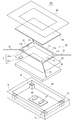
- FIG. 2 is an exploded perspective view showing each component of the information terminal according to Embodiment 1 of the present invention.
- FIG. 3 is a diagram specifically showing the configuration of the actuator that constitutes the tactile force sense presentation device shown in FIG. 2.
- FIG. 4 is a block diagram showing a configuration of the information terminal according to Embodiment 1 of the present invention.
- FIG. 5 is a flowchart showing the operation of the information terminal 100 according to Embodiment 1 of the present invention.
- FIG. 6 is a diagram showing an example of content used in Embodiment 1 of the present invention.
- FIG. 7 is a flowchart specifically showing step S105 shown in FIG. FIG.
- FIG. 8 is a diagram for explaining the calculation process of the tensile force of the actuator.
- FIG. 9 is a diagram illustrating the relationship between the vibration generation timing and the displacement amount of the tactile force sense presentation member.
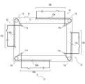
- FIG. 10 is an exploded perspective view showing each component of the information terminal according to Embodiment 2 of the present invention.
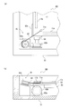
- FIG. 11A and FIG. 11B are diagrams showing a specific configuration of the actuator shown in FIG. 10,
- FIG. 11A is a plan view
- FIG. 11B is a side view.
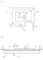
- FIG. 12 is a diagram illustrating an information terminal according to the embodiment.
- FIG. 12A is a plan view and FIG. 12B is a partial cross-sectional view.
- FIG. 13 is a diagram illustrating a relationship between the vibration duration time and the displacement amount of the tactile force sense presentation member in Verification 1 of the example.
- FIG. 14 is a diagram illustrating a result of evaluation by a user in verification 1 of the example.
- FIGS. 15A to 15C are diagrams showing the relationship between the duration of vibration and the amount of displacement of the tactile sensation presentation member in Verification 2 of the example, and the length of the duration of vibration is different. ing.
- FIG. 16 is a diagram illustrating a result of evaluation by a user in verification 2 of the example.
- Embodiment 1 a haptic sense presentation device, an information terminal, a haptic presentation method, and a program according to Embodiment 1 of the present invention will be described with reference to FIGS.
- FIG. 1 is a perspective view showing an external appearance of an information terminal according to Embodiment 1 of the present invention.
- FIG. 2 is an exploded perspective view showing each component of the information terminal according to Embodiment 1 of the present invention.
- the information terminal 100 is a tablet-type information terminal.
- the information terminal 100 includes a display panel 20 that displays content, a touch sensor 30 that detects a position touched by the user (hereinafter referred to as “touch position”), and various types of information. And an information processing unit 40 that executes processing.
- the touch position is detected by the touch sensor 30, and the detected position is information processing.
- the unit 40 is notified.
- the information processing unit 40 receives a user input operation according to the touch position, executes a process of changing the content in response to the received input operation, and displays various contents on the screen 20a of the display panel 20. To do.
- the information terminal 100 includes a haptic sense presentation device 10 that presents a haptic sense to a user who performs an input operation on the screen 20 a of the display panel 20.
- the tactile force sense presentation device 10 includes a tactile force sense presentation member 11 for transmitting a tactile force sense to a user, an actuator 12 for moving the tactile force sense presentation member 11 to present a tactile force sense, and a tactile force sense.
- a vibration generation unit 13 that generates vibration in the presentation member 11 and a control unit 14 that controls the actuator 12 and the vibration generation unit 13 are provided.
- the control unit 14 when the content on the screen 20a of the display panel 20 changes in response to a user input operation on the screen 20a, the control unit 14 is presented with a tactile force sense corresponding to the change in the content. In addition, the actuator 12 is instructed to move the tactile force sense presentation member 11. Further, in the above case, the control unit 14 causes the vibration generating unit 13 to generate vibration in the haptic sense presentation member 11 simultaneously with the start of the movement of the haptic sense presentation member or before the start of the movement. Instruct the generation of vibration.
- the haptic sense presentation device 10 can present a haptic sensation by moving the haptic sense presentation member 11 to the user and also present a vibration having a higher transmission speed.
- the displacement speed of the actuator is slow, the user can be prevented from feeling that the presentation of the tactile force sense is slow. That is, according to the haptic sense presentation device 10, it is possible to make it difficult for the user to feel a time delay in the presentation of the haptic sense without being affected by the performance of the actuator.
- the information terminal 100 can be reduced in size, thickness, and weight.
- the finger of the user 70 is in contact with the virtual sphere displayed on the display panel 20. Thereby, the user 70 feels vibration at the fingertip, and further, the virtual force by the tactile sensation presentation member 11 according to the positional relationship between the virtual sphere and the finger and the operation state (speed, weight) of the virtual sphere. Feel the repulsive force and feel from the ball.
- the “tactile sensation” as used in the present invention means a repulsive force, a resistance force, an external force, a touch, and the like that the user feels.
- the configuration of the information terminal 100 and the haptic sense presentation device 10 according to the first embodiment will be described in more detail.
- the information terminal 100 is roughly composed of five layers.
- the layer on the most user side is the first layer.
- a cover 50 is arranged so that the inside of the information terminal 100 and the end of the haptic sense presentation member 11 are not visible from the outside.
- the cover 50 is formed in a frame shape so that the user can touch the detection area of the touch sensor 30 below the cover 50, but the width is set so that the user can avoid touching the detection area outside. ing.
- the touch sensor 30 is arranged on the second layer.
- a touch panel is used as the touch sensor 30.
- the touch panel is located on the front side of the haptic sense presentation member 11 and is integrated with the haptic sense presentation member 11. For this reason, when the user touches the tactile sensation presentation member 11, the touch panel detects the touched position and outputs data for specifying the position (hereinafter referred to as “touch detection data”). Further, the touch panel is moved by the actuator 12 together with the tactile force sense presentation member 11.
- a tactile sensation presentation unit 11, an actuator 12 for moving the tactile sense presentation unit 11, and a vibration generation unit 13 are arranged.
- the actuators 12 are four wire-like actuators, which are tactile force at each end so that the tactile force sense presentation member 11 moves along the front surface of the display panel 20. It is attached to the sense presentation member 11. Specifically, one end of each wire-like actuator 12 is connected to a through-hole formed in the vicinity of each corner of the tactile force sense presentation member 11 and the other end is connected to a casing 51 described later. The tactile force sense presentation member 11 is moved by each tensile force (see FIG. 4).
- the tactile sensation presentation member 11 is formed in a panel shape from a light-transmitting acrylic resin or the like, and is disposed on the front side of the display panel 20. Furthermore, convex portions 11a and 11b having a semicircular cross section are formed on the surface (rear surface) of the tactile sense presentation member 11 on the display panel 20 side so as to extend along each side. Moreover, the convex parts 11a and 11b prevent the surface of the support panel 23 mentioned later from being damaged by the movement of the tactile force sense presentation member 11.
- the vibration generating unit 13 is disposed on the back surface of the tactile force sense presentation member 11.
- examples of the vibration generating unit 13 include a piezoelectric element, a vibration generating device configured by a semicircular vibrator and a small motor, and the like.
- the vibration generating unit 13 may be attached to the haptic sense presentation member so as to generate vibration, and may be disposed on the surface of the haptic sense presentation member 11.
- a support panel 23 and a display panel 20 are arranged.
- a liquid crystal display panel is used as the display panel 20, but the display method is not particularly limited as long as the display panel 20 is a thin display panel.
- the support panel 23 is a rectangular plate formed to cover the display panel 20 with a transparent resin such as an acrylic resin.
- the support panel 23 is disposed between the haptic sense presentation member 11 and the display panel 20 to support the haptic sense presentation member 11 and protect the display panel 20.
- the third layer tactile sensation presentation member 11 is provided with a light source 31a that emits spot light, and the fourth layer support panel 23 receives spot light emitted from the light source 31a and receives the received light.
- a light receiving element 31b that outputs a signal corresponding to the above is disposed. Since the light source 31b moves together with the haptic sense presentation member 11, the position of the haptic sense presentation member 11 is detected by the light source 31a and the light receiving element 31b.
- the light source 31 a and the light receiving element 31 b function as the position detection sensor 31 of the tactile force sense presentation member 11.
- the light source 31a may be disposed on either the front surface or the back surface of the haptic sense presentation member 11.
- the light receiving element 31b may be disposed on either the front surface or the back surface (surface on the display panel side) of the support panel 23.
- control unit 14 and the information processing unit 40 are arranged.
- the control part 14 and the information processing part 40 are each implement
- FIG. 3 is a diagram specifically showing the configuration of the actuator that constitutes the tactile force sense presentation device shown in FIG. 2.
- each wire-like actuator 12 includes a wire 12a formed of a shape memory alloy, and an energization heating device that heats the wire 12a by energization to return to the original shape. 12b. Further, one end of each wire 12a is connected to a hole 11a provided near each corner of the tactile force sense presentation member 11, and the other end is connected to a casing 51 to be described later.
- the size of the actuator 12 can be reduced, and the information terminal 100 can be reduced in size, thickness, and weight.
- the wire 12a formed of the shape alloy has an advantage that the tensile force is large, and an advantage that the amount of displacement can be increased by setting the wire 12a in a state of being greatly extended.
- the wire 12a formed of a shape memory alloy is operated by heating by energization, and thus has a disadvantage that the reaction during cold is particularly slow and a disadvantage that the displacement speed is slow.
- vibration is also presented. For this reason, the situation which a user feels that presentation of a tactile force is late is avoided by the said fault.
- pulleys 15 are respectively provided in the squares inside the casing 51 in order to increase the degree of freedom of layout while increasing the displacement amount of the wire 12a as much as possible.
- Each wire 12a is arranged in a state where the tension direction is changed by the corresponding pulley 15.
- FIG. 4 is a block diagram showing a configuration of the information terminal according to Embodiment 1 of the present invention.
- the information processing unit 40 is connected to the display panel 20, the touch sensor 30, and the control unit 14.
- the control unit 14 is connected to the energization heating device 12 b constituting the actuator 12, the vibration generating unit 13, the position detection sensor 31, and the time management unit 16.
- the touch sensor 30 detects the position of the user's finger ( Touch position) is detected, and touch detection data a for specifying the touch position is output to the information processing unit 40.
- the information processing unit 40 When the information processing unit 40 receives the touch detection data a, the information processing unit 40 refers to the content data 41, performs a process of linking the touch position and the movement of the object in the content, and displays the display information of the content reflecting the processing content.
- the display information is generated and output to the display panel 20 as display data f.
- the display panel 20 Upon receiving the display data f, the display panel 20 displays an image corresponding to the received display data f on the display screen 20a (see FIG. 1).
- the content data 41 include application program data that provides a virtual space, such as a game program and a simulation program, and Web site data. Further, the content data 41 may be stored in a storage device provided in the information terminal 100, or may be stored in another device (computer) connected via the Internet.
- the information processing unit 40 calculates the force generated in the virtual space for the object and specifies data b (hereinafter referred to as “presentation data b”) for specifying the calculated force in the control unit 14. Output.
- the calculated force is a repulsive force generated in the object, and corresponds to a tactile force sense to be transmitted to the user.
- the control unit 14 receives the presentation data b and the data c output from the position detection sensor 31.
- the data c output from the position detection sensor 31 is data (hereinafter referred to as “position detection data”) c that specifies the position of the tactile force sense presentation member 11.
- the control unit 14 uses the presentation data b and the position detection data c to calculate the tensile force that each actuator 12 (wire 12a) should output. This calculation is performed so that the tactile force sense specified by the presentation data b is transmitted to the user 70 when the tactile force sense presenting member 11 moves along the horizontal plane.
- control part 14 produces
- control part 14 produces
- each energization heating device 12b energizes the corresponding wire 12a, and each wire 12a exhibits the calculated tensile force, so that the tactile force sense presentation member 11 is pulled, and the fingertip of the user 70 is The tactile sensation specified by the presentation data b is presented.
- time management unit 16 manages the duration of vibration by the vibration generation unit 13 and outputs data (hereinafter referred to as “timer management data”) e for specifying the duration to the control unit 14.
- timer management data data
- the control unit 14 receives the timer management data e, the vibration generating unit at a timing at which the movement of the tactile sensation presentation member 11 is started for the duration specified by the timer management data e, or at a timing before the start of the movement. 13 is vibrated.
- the control unit 14 when the vibration generating unit 13 is a piezoelectric element, the control unit 14 generates a signal for driving the piezoelectric element, and supplies this as vibration control data g to the piezoelectric element. If the vibration element 13 is composed of a semicircular vibrator and a small motor, the control unit 14 generates a signal for driving the motor and uses this as vibration control data g for the motor. To supply.
- FIG. 5 is a flowchart showing the operation of the information terminal 100 according to Embodiment 1 of the present invention.
- FIGS. 1 to 4 are referred to as appropriate.
- the haptic sense presentation method is implemented by operating the haptic sense presentation device 10. Therefore, the description of the haptic sense presentation method in the present embodiment is replaced with the following description of the operation of the haptic sense presentation apparatus 10.
- the user 70 views the content displayed on the display panel 20 that is seen through the haptic sense presentation member 11, and operates the object in the virtual space provided by the content. Therefore, the touch sensor 30 is touched. Thereby, as shown in FIG. 5, the touch sensor 30 detects the touch position of the user's finger, and outputs touch detection data a for specifying the detected touch position to the information processing unit 40 (step S101).
- the information processing unit 40 when receiving the touch detection data a output in step S101, the information processing unit 40 refers to the content data 41 and executes a process of changing an object in accordance with the touch position (content interlocking process) (step). S102).
- step S102 the information processing section 40 generates content display information in which the content interlocking process is reflected, and outputs the display information to the display panel 20 as display data f. Further, in step S ⁇ b> 102, the information processing unit 40 calculates the force generated in the virtual space on the object, and outputs the presentation data b specifying the calculated force to the control unit 14. Details of step S102 will be described later with reference to FIG.
- control unit 14 receives the position detection data c from the position detection sensor 31, and specifies the position of the haptic sense presentation member 11 detected by the position detection sensor 31 (step S103). Further, the control unit 14 receives the timer management data e from the time management unit 16 and specifies the duration of vibration generation by the vibration generation unit 13 (step S104). Note that the order of steps S103 and S104 may be the same or may be switched.
- control unit 14 determines the haptic sense based on the presentation data b output in step S102, the position of the haptic sense presentation member 11 specified in step S103, and the duration specified in step S104. Processing for presentation (tactile force sense presentation control processing) is executed (step S105).
- step S105 the control unit 14 causes the haptic sense presentation member 11 to generate a target haptic sense based on the presentation data b and the position of the haptic sense presentation member 11.
- Force control data d is generated by calculating control amounts of the four actuators 12, and is output to each actuator 12.
- the control unit 14 generates vibration control data g and outputs the vibration control data g to the vibration generation unit 13 in order to cause the tactile force sense presentation member 11 to generate vibration for the specified duration. Details of step S105 will be described later with reference to FIG.
- step S105 the haptic sense presentation device 10 presents vibration and a haptic sense due to movement of the haptic sense presentation member 11 to the fingertip of the user 70 (step S106). Further, the content after the content linkage processing is displayed on the display screen 20a of the display panel 20 based on the display data e output from the information processing unit 40 in step S102 (step S107). Note that step S106 and step S107 may be executed simultaneously.
- steps S101 to S107 are repeatedly executed. Therefore, when the user 70 performs a drag operation from one point to another point, steps S101 to S107 are repeatedly executed from the start to the end of the drag. Can receive presentation of vibration and tactile sensation.
- steps S101, S102, and S105 shown in FIG. 5 will be described in more detail with reference to FIGS.
- FIG. 6 is a diagram showing an example of content used in Embodiment 1 of the present invention.
- the content is an air hockey game
- the user 70 hits the virtual pack 22 by operating the virtual mallet 21 existing in the virtual space by touching the fingertip.
- Step S ⁇ b> 101 the touch sensor 30 executes Step S ⁇ b> 101 and outputs touch detection data a that specifies the touch position of the finger of the user 70 to the information processing unit 40.
- step S102 the information processing unit 40 executes content interlocking processing to link the movement of the finger, which is an operation in the real space, with the movement of the virtual mallet 21 and the virtual pack 22 in the virtual space.
- the information processing unit 40 moves the virtual mallet 21 so as to follow the movement of the finger by the touch of the user 70, and the virtual object in the virtual space and the real space object (the finger of the user 70) Take the interaction.
- the information processing unit 40 executes a physical simulation in the virtual space, and simulates a change in position and a contact force when the virtual mallet 21 and the virtual pack 22 come into contact with each other by the touch of the user 70. .
- the information processing unit 40 When the information processing unit 40 receives the touch detection data a, the information processing unit 40 moves the virtual mallet 30 to the detected touch position. At this time, if the virtual mallet 30 is moved discontinuously to the touch position, the virtual objects May overlap each other. In this case, accurate simulation becomes difficult.
- the information processing unit 40 executes PD (Proportional-Deferential) control in which a force proportional to the distance from the virtual mallet 21 to the touch position and the speed of the virtual mallet 21 is applied to the virtual mallet 21, while performing virtual mallet. 21 is moved.
- PD Proportional-Deferential
- the information processing unit 40 makes contact with the virtual mallet 21 and the virtual pack 22 according to physical coefficients in the virtual space of the virtual mallet 21 and the virtual pack 22. Calculate the reaction force generated in.
- a physical coefficient the mass of each of the virtual mallet 21 and the virtual pack 22, a speed, an acceleration, a contact direction, a restitution coefficient, etc. are mentioned.
- the reaction force received from the virtual pack by the virtual mallet 21 corresponds to a tactile force sense to be presented to the user 70 by the tactile force sense presenting member 11 (FIG. 6 and later-described drawings). 8). Therefore, when the reaction force received by the virtual mallet 21 from the virtual pack is “presentation force F”, the information processing unit 40 causes the presentation force F to be presented by the haptic sense presentation member 11. Is output to the control unit 14. Further, the information processing unit 40 outputs data for displaying movements of the virtual mallet 21 and the virtual pack 22 to the display panel 20 as display data f that is display information.
- FIG. 7 is a flowchart specifically showing step S105 shown in FIG.
- FIG. 8 is a diagram for explaining the calculation process of the tensile force of the actuator.
- step S105 the control unit 14 first uses the presentation data b and the position detection data c to move the tactile force sense presentation member 11 along the horizontal plane.
- the tensile force of 12a) is calculated (step S201).
- the position of the tactile force sense presentation member 11 is represented by (x, y), and the origin (0, 0) of the coordinates is set at the center of the rectangle S. Further, in the haptic sense presentation member 11 in FIG. 8, it is assumed that one end of the wire 12a of the actuator 12 is connected to each corner.
- the rectangle S is set such that the distance from the corner of the tactile force sense presentation member 11 to the corresponding corner of the rectangle S corresponds to the length (l 1 to l 4 ) of each wire 12a.
- H indicates the vertical length of the rectangle S
- W indicates the horizontal length of the rectangle S.
- h indicates the vertical length of the haptic sense presentation member 11
- w indicates the horizontal length of the haptic sense presentation member 11.
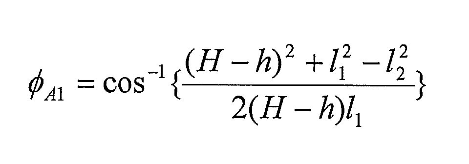
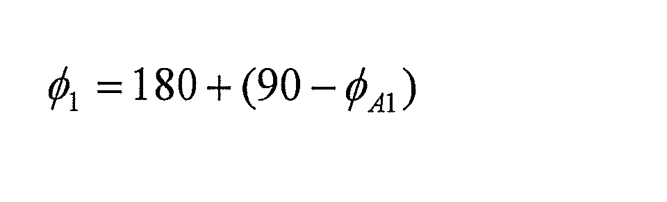
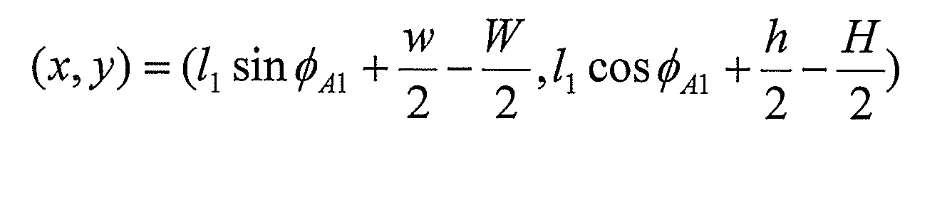
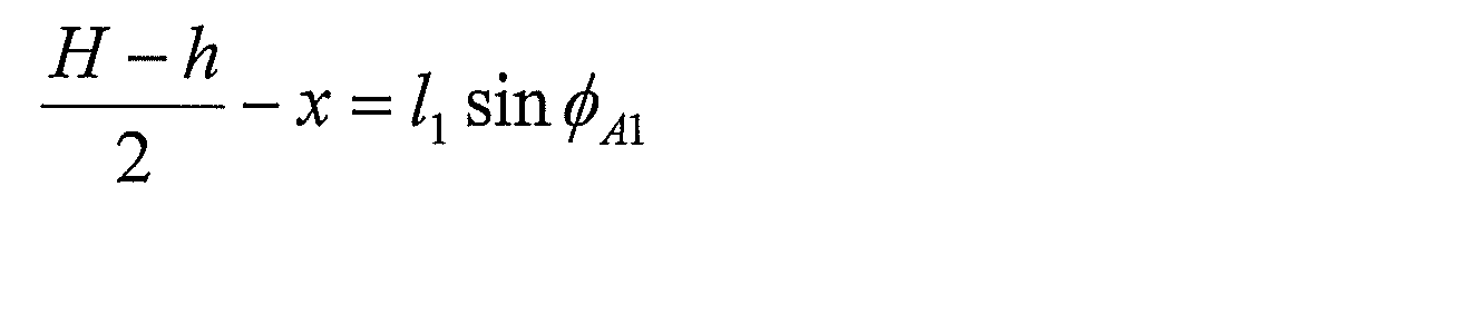
- step S201 first, when the position detection data b is output from the position detection sensor 31, the control unit 14 specifies the position (x, y) of the haptic sense presentation member 11 and the known length. Based on the length (H, W, h, w), the angle ( ⁇ 1 to ⁇ 4 ) of each actuator used for calculation of the tensile force is calculated.
- control unit 14 calculates ⁇ 1 by applying the coordinates (x, y) and the known value to Equations 1 to 6. Also, ⁇ 2 to ⁇ 4 are calculated in the same procedure.
- control unit 14 outputs each actuator 12 using the presentation data b output in step S102, the coordinates (x, y) acquired in step S103, and the calculated ⁇ 1 to ⁇ 4 .
- the power tensile forces ⁇ 1 to ⁇ 4 are calculated.
- the positions of the four vertices of the tactile force sense presentation member 11 are represented by position vectors based on the center of gravity positions, that is, r 1 , r 2 , r 3 , r 4 .
- the direction of each of the position vectors r 1 , r 2 , r 3 , r 4 depends on the vertical length h and the horizontal length w of the haptic presentation member 11. Determined by. Further, since the distance from the center of gravity position to each vertex is the same, the amount of each position vector is the same. Further, in FIG. 8, M is a moment for rotating the tactile force sense presentation member 11 around its center of gravity, and the moment M is generated according to the balance relationship of the tensile forces ⁇ 1 to ⁇ 4 .
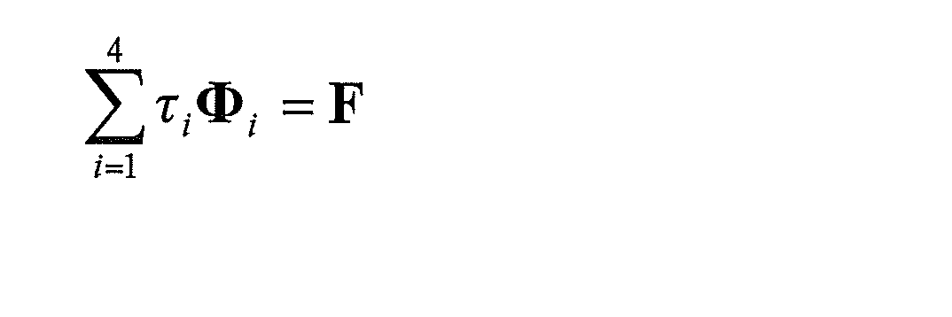
- the control unit 14 calculates the tensile forces ⁇ 1 to ⁇ 4 so that the following conditions (a) to (d) are satisfied.
- Equation 7 the resultant force of the tensile forces ⁇ 1 to ⁇ 4 is the sum of the inner products of each tensile force and the corresponding angle of the actuator 12. Therefore, it is necessary that the sum of the inner products and the target presentation force F match.
- the moment M in the condition (b) is set to 0 (zero) in the first embodiment. Therefore, the condition (b) can be expressed by the following formula 8. As shown in Equation 8, the moment M is the sum of the outer products of the position vectors r 1 to r 4 and components in the direction from the corners of the tactile force sense presentation member 11 toward the center of gravity at each tensile force. It is necessary that the sum of the outer products be 0 (zero). In addition, when it is desired to generate a set moment in the haptic sense presentation member 1, an arbitrary value is substituted for the value of M, and the obtained number 8 may be used.
- condition (c) is set in order to prevent any actuator 12 from loosening and the haptic sense presentation member 11 from moving in parallel with the xy plane. Further, if the tensile force is too large, the wire is likely to be cut. Therefore, the maximum value of the tensile force is set in the condition (c).
- Condition (c) can be expressed by Equation 9 below.
- the condition (d) is set to optimize the tensile forces ⁇ 1 to ⁇ 4 as described above, that is, to minimize the energy consumption in each actuator 12. If the condition (d) is not set, the tensile forces ⁇ 1 to ⁇ 4 may become unnecessarily large.
- Equation 10 Equation 10
- the function shown in Formula 10 aims at minimizing the sum of the tensile forces caused by these while increasing the efficiency of each actuator 12.
- J is an objective function value set for optimization.
- the tensile forces ⁇ 1 , ⁇ 2 , ⁇ 3 , ⁇ 4 are calculated so that J is minimized.
- linear programming which is one of optimization calculation methods is executed.
- a target presentation force F is generated by the resultant force of the tensile forces ⁇ 1 , ⁇ 2 , ⁇ 3 , and ⁇ 4 of the four actuators 12.
- control unit 14 calculates the power to be supplied by the corresponding energization heating device 12b for each actuator 12 so that the tensile force calculated in step S201 is exhibited by each actuator 12. And the control part 14 produces the haptic control data d which enables supply of the calculated electric power, and outputs this to the electricity heating apparatus 12b of each actuator 12 (step S202).
- control unit 14 sets the generation timing of vibration (step S203). Thereafter, the control unit 14 generates vibration control data d based on the duration specified in step S104, and outputs the vibration control data d to the vibration generation unit 13 at the timing set in step S203 (step S204). ).
- FIG. 9 is a diagram illustrating the relationship between the vibration generation timing and the displacement amount of the tactile force sense presentation member.
- the horizontal axis represents the elapsed time t
- the vertical axis represents the displacement amount of the haptic sense presentation member 11.
- the amount of displacement includes both the amount of movement of the tactile force sense presentation unit 11 along the horizontal plane due to the tension of the actuator 12 and the amount of movement of the tactile force presentation unit 11 due to vibration by the vibration generation unit 13. .
- the former amount of displacement is displayed with a broken line
- the latter amount of displacement is displayed with a solid line.
- the response speed of the vibration generating unit 13 is fast, and the time from when the control unit 14 instructs the generation of vibration until the actual generation of vibration is extremely short. Almost simultaneously with the start of movement, vibration is generated in the tactile sense providing member 11. For this reason, immediately after the occurrence of an event that requires presentation of a tactile force sense, the user 70 can notice that the tactile force sense is being presented.
- steps S203 and S204 are executed, even if a time lag occurs in the presentation of the tactile sensation due to movement, the user 70 can feel vibration during this time. As a result, it is suppressed that the user feels a time delay in presenting the tactile sensation.
- the program in the first embodiment may be a program that causes a computer to execute steps S103 to S106 shown in FIG.
- a CPU Central Processing Unit
- the computer capable of realizing the haptic sense presentation device 10 is not particularly limited, and may be the above-described microcomputer or a general-purpose personal computer. Further, the computer capable of realizing the tactile sensation presentation device 10 may be a computer provided in a mobile phone, a smartphone, or a tablet information terminal.
- the program in the first embodiment may be provided in a state of being recorded on a computer-readable recording medium, or may be transmitted via the Internet.
- the recording medium include a general-purpose semiconductor storage device such as CF (Compact Flash (registered trademark)) and SD (Secure Digital), a magnetic storage medium such as a flexible disk, or a CD-ROM.
- Optical storage media such as (Compact Disk Read Only Memory).
- the tactile force sense due to the movement of the tactile force sense presentation member 11 and the vibration having a high transmission speed can be combined and presented to the user. It can make it difficult to feel the time delay of the presentation. As a result, the following effects can be obtained.
- the information terminal 100 can be reduced in size, thickness, and weight.
- tactile sensations and vibrations can be presented, combining them makes it possible to expand the variations of expression in tactile sensation presentation.
- FIG. 10 is an exploded perspective view showing each component of the information terminal according to Embodiment 2 of the present invention.
- FIG. 11A and FIG. 11B are diagrams showing a specific configuration of the actuator shown in FIG. 10, FIG. 11A is a plan view, and FIG. 11B is a side view.
- the information terminal 200 and the haptic sense presentation device 80 according to the second embodiment are the same as the information terminal 100 and the tactile sense presentation device 80 according to the first embodiment shown in FIGS. This is different from the haptic sense presentation device 10.
- the difference from the first embodiment will be mainly described.
- the touch sensor 60 is different from the touch panel used in the first embodiment, and is parallel to the frame-shaped frame 60a and one of the two opposite sides. And a plurality of light receiving elements 60c arranged in parallel to the other side.
- a part of the light emitting element 60b is arranged to be able to irradiate light along the vertical direction of the screen, and the rest is arranged to be able to irradiate light along the horizontal direction of the screen. For this reason, when a part of the irradiated light is blocked by the finger of the user 70 tracing the surface of the haptic sense presentation member 11, the blocked part is detected as a touch position.
- the touch sensor 60 also outputs to the information processing unit 40 touch detection data a that specifies the detected touch position.
- the actuator 61 includes a wire 62 and a wire pulling portion 63.
- One end of each wire 62 is connected to the haptic sense presentation member 11 by a through hole 11 c provided near the corner of the haptic sense presentation member 11.
- Each wire tension portion 63 includes a motor 63a functioning as an actuator, a pulley 63b for winding the wire 62, and a tension direction changing pulley 63c.
- the rotational force by the motor 63a is transmitted as a tensile force to the tactile force sense presentation member 11 via the wire 62.
- the tactile force sense presentation unit 1 is pulled and the user 70 (see FIG. 1). ) Is presented with tactile sensation.
- the rotational force of the motor 63 a is converted into a linear tensile force along the side surface of the casing 51 by the pulley 63 b that winds the wire 62.
- the tensile force is applied from the through hole 11 c of the tactile force sense presentation member 11 to the corner of the casing 51 from the linear direction along the side surface of the casing. It is converted to the direction toward. Therefore, when the motor 63a is activated, the tactile force sense presentation member 11 is pulled toward the tension direction changing pulley 63c by the generated tensile force.
- convex portions 11 a and 11 b formed on the haptic sense presentation member 11 are provided between the support panel 23 and the haptic sense presentation member 11. A space is provided, and the wire 62 is guided to the wire pulling portion 63 through this space. Furthermore, since the cross sections of the convex portions 11a and 11b are semicircular and the convex portions 11a and 11b are in contact with the support panel 23 by a line, the surface of the support panel is prevented from being damaged by the movement of the tactile sense presentation member 11. Is done.
- each motor 63a is provided with a sensor 64 for detecting the rotational speed of the motor 63a.
- the sensor 64 outputs data specifying the detected number of rotations to the control unit 14 (see FIG. 10).
- a specific example of the sensor 64 is an optical rotary encoder.
- the second embodiment although the size of the actuator is increased, a large force can be applied to the tactile force sense presentation member 11, and thus the second embodiment is effective when the size of the display panel 20 is large. It is.
- the presentation power can be increased while the motor is downsized.
- the displacement speed of the tactile force sense presentation member 11 is reduced, but due to the vibration by the vibration generating unit 13, it is difficult to feel the time delay of the tactile force sense presentation by the user as in the first embodiment.
- the tension direction changing pulley 63c which is the starting point of tension when the wire 62 is pulled toward the housing 51, is connected to each other.
- the position of the starting point of tension is not particularly limited, and the starting point of each tension is such that, for example, a parallelogram or trapezoid is formed when they are connected with a line. May be arranged.
- tensile_strength does not need to be located in the same plane, and the number does not need to be four points.
- the operations of the information terminal 200 and the haptic sense presentation device 80 are the same as the operations shown in FIG. 5 in the first embodiment. Also in the second embodiment, the haptic sense presentation method is implemented by operating the haptic sense presentation device 80. Furthermore, the program in the second embodiment may be a program that causes a computer to execute steps according to steps S103 to S106 shown in FIG.
- the display panel 20 does not move together with the haptic sense presentation member 11, but even if the display panel 20 also moves together with the haptic sense presentation member 11. good. Furthermore, instead of the transparent panel shown in FIG. 2, the display panel 20 itself may be used as the tactile force sense presentation member 11.
- the information processing unit 40 moves and displays the content video in the direction opposite to the moving direction of the display panel 20 in order to prevent the content video from moving in conjunction with the display panel 20 when viewed from the user. It is preferable to execute such a process.
- actuators are used to move the haptic sense presentation member 11 along the horizontal plane, but the number of actuators is not particularly limited. For example, if the tactile sensation presentation member is moved in an arbitrary direction on a plane to present a tactile sensation, there may be at least three actuators.
- the tactile sensation presentation member is moved in an arbitrary direction on a straight line and a tactile sensation is presented, two actuators are sufficient. Further, if the tactile force sense presentation member is moved using balance with an external force such as gravity to present a tactile force sense, the number of actuators may be one. In addition, if the tactile force sense presentation member 11 is moved or rotated in any direction on a plane and in a three-dimensional space to present a tactile force sense, the number of actuators may be four or more.
- the haptic sense presentation member 11 only moves along a horizontal plane (the front surface of the display panel 20).
- the direction of movement of the haptic sense presentation member 11 is as follows. Is not limited to this.
- the moving direction of the tactile force sense presentation member 11 by the actuator may be a direction perpendicular to the horizontal plane.
- the shape of the tactile sensation presentation member 11 is not limited to a panel shape in the present invention.
- the haptic sense presentation device may include a configuration (for example, a glove-shaped configuration) that feeds back the haptic sense to each joint of the user's finger.
- the haptic sense presentation device may be one in which the haptic sense presentation member has a pen shape.
- the actuator is not limited to those shown in the first and second embodiments.
- the actuator may be configured to include a link mechanism.
- the actuator may be provided with a function of releasing gas. In this case, the tactile sensation is also presented by releasing the gas.
- FIG. 6 an example in which a tactile sensation is presented when an object moves in the virtual space in conjunction with the movement of the user's finger is shown (FIG. 6).
- Reference but not intended to be limited to this.
- Embodiments 1 and 2 can also be applied when the object changes other than movement, for example, when the shape, color, size, etc. of the object changes.
- the tactile sensation to be presented may be different depending on the object that is the target of the operation by the user.
- the information processing unit 40 that performs processing for content display is housed in the same housing together with the display panel, the touch sensor, and the tactile sense presentation device. It is not limited to this.
- the information processing unit 40 may be realized by a computer such as an external personal computer.
- the control unit 14 may also be realized by a computer that implements the information processing unit.
- the tactile sensation presentation device can be applied to navigation of movement. For example, when navigating a destination to a walking user, the tactile force sense presenting device can present the direction to travel to the finger that the user is touching with a tactile force sense. In this case, the navigation direction becomes information that is desired to be presented as content.
- the tactile sensation presentation device can provide the user with a more substantial operational feeling by presenting a haptic sensation linked to the movement of the scrolling screen.
- a display method is known in which, when there is no more information in scrolling the screen, the display screen is bound in the scroll direction to notify that the screen cannot be scrolled.
- this display method is adopted, if the tactile sensation is presented in conjunction with the bounce of the display screen, the user can receive information more quickly and accurately.
- the tactile sensation presentation device can present by tactile sensation that there is a link button or the like under the finger being touched when the displayed content is a web site. it can.
- the user can receive information that is difficult to obtain with display information alone.
- the haptic sense presentation device can also give a warning by presenting the haptic sense so that the user can hardly press the link button.
- the tactile sensation presentation device is not limited to being interlocked with a virtual object (virtual object) but can be used for an operation reaction of an input operation such as a master / slave robot arm.
- a virtual object virtual object
- the tactile sensation presentation device responds that the obstacle has been touched, a warning before touching the obstacle, etc. A tactile sensation can be presented. In this case, the user can operate the robot arm more safely and accurately.
- the tactile force sense presentation device can be used for grasping the state of a tactile map or the like. That is, the tactile sensation presentation device can be used as a map grasp for a visually handicapped person.
- the tactile sensation presentation device presents a tactile sensation corresponding to the wall and the road, the user can easily grasp the shape and state. Become.
- the tactile sensation presentation device can be used for presenting information on the kanji writing order in character learning.
- the tactile sensation presentation device is useful for assisting character learning.
- the tactile sensation presentation device can present a haptic sensation that is moved in a direction parallel to the display panel as feedback of a click sensation during device operation. Further, feedback by tactile force sense is important in key operation for input, and thus the tactile force sense presenting apparatus can change the feedback so that it can be easily understood by the user. Furthermore, when the user's input changes, the tactile sensation presentation device can make the user aware of the input change by returning a feedback different from the conventional click feeling.
- an input method called a flick method is known as a character input method using a touch panel.
- the input character is determined by the position touched by the finger and the direction in which the finger is slid.
- the tactile sensation presentation device according to the first and second embodiments is applied to this flick method, it becomes easier for the finger to slide only in the sliding direction, and resistance to the movement of the finger in the direction that cannot be selected by sliding occurs.
- the sense of touch can be presented. In this case, it is possible to prevent the user from making an erroneous movement when selecting a character, and it becomes easy to input the character.
- the tactile sensation presentation device can be used as a feedback device in simulation of musical instrument operations such as a piano, surgery simulation, and clay modeling simulation. That is, the haptic sense presentation device can present the haptic sense as feedback of the device with respect to input as one of prior learning and entertainment of device use.
- the tactile sensation presentation device can be used for product state recognition when purchasing a product other than an actual store such as a Web site or a television. Unlike merchandise purchase at an actual store, the actual feeling of the merchandise becomes a problem in merchandise purchase on a website and a television. For this reason, if the tactile sensation presentation device is used, the user can obtain tactile information when the product is touched, so that the user can make a purchase after understanding the product.
- the tactile sensation presentation device can be used as entertainment such as understanding an illusion picture.
- the haptic sense presentation device presents the user with a sense of discomfort by giving the haptic sense that does not match the visual information as the presentation information.
- an illusion picture with a spiral staircase created by Maurits CornelisEscher cannot be touched as a real thing, but a tactile sensation presentation device can be used to present the feel of an object in virtual space, so the user touches the illusion picture.
- FIG. 12 is a diagram illustrating an information terminal according to the embodiment.
- FIG. 12A is a plan view and
- FIG. 12B is a partial cross-sectional view.
- the tactile sensation presentation member 11 is composed of two transparent panels 11d and 11e.
- a piezoelectric element is used as the vibration generating unit 13, and the two piezoelectric elements are sandwiched between the panel 11d and the panel 11e.
- the actuator used for moving the tactile force sense presentation member 11 is the same as the example shown in FIGS. 10, 11 (a) and 11 (b) in the second embodiment. It is comprised by the tension
- the tactile force sense presentation member 11 moves along a horizontal plane by pulling with the wire 62 using a motor, and presents a tactile force sense.
- the virtual sphere 110 collides with the cube 111, and the tactile force according to the collision is applied to the finger of the user 70.
- the sense of vision is presented.
- FIG. 13 is a diagram illustrating the relationship between the vibration duration time and the displacement amount of the tactile sensation presentation member in Verification 1 of the example.
- the generation of the tactile force sense is necessary, the generation of the vibration is first executed, and then the movement of the tactile sense presentation member by the actuator is started.
- a pseudo time delay is generated before the tactile force sense is presented by the actuator, and the user is evaluated for the time delay at that time.
- T F is the delay time of the presentation of the haptic by the actuator indicates (presentation delay time)
- T V represents the duration of the vibration
- T o represents the presentation time of the haptic by the actuator ing.
- T F T V.
- the presentation delay time TF is set to 0.0 [s], 0.25 [s], 0.5 [s], 0.75 [s], and 1.00 [s] by five users.
- the five cases were evaluated with five grades from “I feel no delay” to “I feel there is a delay”. The results are shown in FIG.
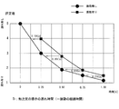
- FIG. 14 is a diagram illustrating a result of evaluation by a user in verification 1 of the example. 14, the horizontal axis represents the delay time T F of the presentation of the haptic by the actuator, and the vertical axis represents the evaluation value.
- the evaluation by the user is performed when vibration is presented before the tactile sensation is presented by the actuator ( ⁇ in the figure) and when vibration is not presented (in FIG. 14). This is done for both of them.
- the rating value on the vertical axis is an average value of the rating values of five users.
- the presentation by vibration when the presentation by vibration ( ⁇ in the figure) is performed before the presentation of the tactile force sense by the actuator, it is significant compared with the case where the presentation by vibration is not given ( ⁇ in the figure). There are many users who feel that there is no delay, and it can be seen that the rating value is high. Specifically, the presentation by vibration may make it difficult for the user to feel the time delay of the tactile sensation presentation by about 0.2 [s] compared to the case where the presentation by vibration is not performed. It is possible.
- FIGS. 15A to 15C are diagrams showing the relationship between the duration of vibration and the amount of displacement of the tactile sensation presentation member in Verification 2 of the example, and the length of the duration of vibration is different. ing.
- the verification 2 of this embodiment as in the verification 1, when the generation of the tactile force sense is necessary, the generation of the vibration is first performed, and then the tactile sense is performed. The movement of the presentation member by the actuator is started. In verification 2, verification is performed for the three patterns in FIGS. 15 (a) to 15 (c).
- T F is the delay time of the presentation of the haptic by the actuator indicates (presentation delay time)
- T V represents the duration of the vibration
- T o is haptic by the actuator Shows the presentation time.
- FIG. 15A shows a pattern (interval: T F > T V ) in which the vibration presentation is terminated before the start of the presentation of the tactile force sense by the actuator, and the “interval” is temporally separated.
- FIG. 15C shows a pattern (duplication: T F ⁇ T V ) in which the continuation of vibration and the presentation of the tactile force sense by the actuator are “overlapping”.
- the presentation delay time TF is 0.0 [s], 0.25 [s], 0.5 [s] for each pattern shown in FIGS. , 0.75 [s] and 1.00 [s] were evaluated with five grades from “I feel no delay” to “I feel there is delay”. The results are shown in FIG.
- FIG. 16 is a diagram illustrating a result of evaluation by a user in verification 2 of the example. Also in FIG. 16, the horizontal axis represents the delay time T F of the presentation of the haptic by the actuator, and the vertical axis represents the evaluation value. FIG. 16 shows the user's evaluation in each of the above three patterns.
- “ ⁇ ” indicates the pattern (interval) shown in FIG. 15A
- “ ⁇ ” shows the pattern (simultaneous) shown in FIG. 15B
- ⁇ ” shows in FIG. 15C. Indicates the pattern to be shown (overlapping).
- FIG. 16 shows that when the vibration presentation is terminated before the start of the presentation of the tactile force sense (force sense presentation) by the actuator, the user feels a time delay of the force sense presentation significantly compared to the other cases. It is difficult.
- the presentation of the tactile sensation by the actuator and the presentation of the tactile sensation by vibration are started at the earliest possible timing after the occurrence of an event that requires tactile force presentation.
- an actuator having a high displacement speed is used, but the present invention is not limited to this.
- an actuator having a low displacement speed can be used. In this case, it is preferable that the tactile force sense presentation by vibration is performed at the earliest possible timing.
- a tactile sensation presentation device characterized by the above.
- the tactile sensation presentation member has a light-transmitting panel shape and is disposed on the front side of the display panel;
- the actuator moves the haptic sense presentation member along the front surface of the display panel;
- the tactile sensation presentation device according to attachment 1.
- the control unit instructs the vibration generation unit to generate vibration until the movement of the haptic sense presentation unit is completed with respect to the vibration generation unit.
- the tactile force sense presentation device according to appendix 1 or 2.
- Appendix 4 A time management unit that manages the duration of vibration by the vibration generation unit and outputs data specifying the duration to the control unit;
- the control unit causes the vibration generation unit to generate vibrations for the duration specified by the output data.
- the tactile force sense presentation device according to any one of appendices 1 to 3.
- the actuator is a plurality of wire-like actuators;
- the plurality of wire-like actuators are connected to the haptic sense presentation member at each one end, and move the haptic sense presentation member by respective tensile forces.
- the tactile force sense presentation device according to any one of appendices 1 to 4.
- a display panel that displays content on the screen, A touch sensor for detecting a position touched by a user on the screen; An information processing unit that accepts an input operation according to a position detected by the touch sensor, and changes the content in response to the accepted input operation;
- a tactile force presentation device capable of presenting a tactile force sense to the user,
- the haptic sense presentation device includes: A tactile force presentation member for transmitting a tactile force sense to the user; An actuator for moving the haptic sense presentation member for presenting the haptic sense; A vibration generating unit that generates vibration in the tactile force sense presentation member; A control unit for controlling the actuator and the vibration generating unit, The control unit, when content on the screen of the display panel is changed by the information processing unit corresponding to the input operation of the user on the screen, Instructing the actuator to move the tactile force presentation member so that the tactile force sense corresponding to the change in the content is presented, Instructing the vibration generation unit to generate vibration so that vibration is generated in the haptic sense presentation member simultaneously with the start of the movement of
- the tactile sensation presentation member has a light-transmitting panel shape and is disposed on the front side of the display panel;
- the touch sensor is a touch panel disposed on the front side of the tactile force sense presentation member,
- the actuator moves the tactile force sense presentation member together with the touch sensor along the front surface of the display panel.
- the touch sensor is a touch panel disposed on the front side of the display panel, The touch panel functions as the haptic sense presentation member, or the touch panel and the display panel function as the haptic sense presentation member.
- the control unit instructs the vibration generation unit to generate vibration until the movement of the haptic sense presentation unit is completed with respect to the vibration generation unit.
- the information terminal according to any one of appendices 7 to 9.
- Appendix 11 A time management unit that manages the duration of vibration by the vibration generation unit and outputs data specifying the duration to the control unit;
- the control unit causes the vibration generation unit to generate vibrations for the duration specified by the output data.
- the information terminal according to any one of appendices 7 to 10.
- the actuator is a plurality of wire-like actuators;
- the plurality of wire-like actuators are connected to the haptic sense presentation member at one end of the plurality of wire-like actuators, and move the haptic sense presentation member by respective expansion or contraction.
- the information terminal according to any one of appendices 7 to 11.
- (Appendix 14) A method for presenting a tactile sensation to a user who performs an input operation on a display panel screen, A tactile force presentation member for transmitting a tactile force sense to the user, an actuator for moving the tactile force sense presentation member for presenting the tactile force sense, and a vibration in the tactile force sense presentation member Using a device including a vibration generator, (A) When the content on the screen of the display panel changes in response to the input operation of the user on the screen, the haptic sense corresponding to the change in the content is presented.
- a tactile force sense presentation method characterized by comprising:
- a tactile force presentation member for transmitting a tactile force sense to a user who performs an input operation on a screen of a display panel; and an actuator for moving the tactile force sense presentation member for presenting the tactile force sense;
- the apparatus comprising a vibration generating unit and a computer for generating vibration in the tactile force sense presentation member
- the computer In the computer, (A) When the content on the screen of the display panel changes in response to the input operation of the user on the screen, the haptic sense corresponding to the change in the content is presented.
- the program is (C) further comprising a command for causing the computer to execute a step of managing a duration of vibration by the vibration generation unit and outputting data specifying the duration to the control unit;
- the vibration generator is caused to generate a vibration for the duration specified by the data output in the step (c).
- the computer-readable recording medium according to appendix 17 or 18.
- the present invention it is possible to make it difficult for the user to feel the time delay of the presentation of the tactile force without being affected by the performance of the actuator in the presentation of the tactile force.
- the present invention is useful in various fields that require presentation of tactile sensation, such as computer interfaces, various simulations, and games.
- Tactile sensation presentation device (Embodiment 1) DESCRIPTION OF SYMBOLS 11 Tactile-force sense presentation member 11a, 11b Protrusion part 11c Through-hole 11d, 11e Panel 12 Actuator 12a Wire formed with shape memory alloy 12b Electric heating apparatus 13 Vibration generating part 14 Control part 15 Pulley 16 Time management part 20 Display panel 21 Virtual mallet 22 Virtual pack 23 Support panel 30 Touch sensor (touch panel) 40 Information processing section 41 Content data 50 Cover 51 Case 60 Touch sensor 60a Frame 60b Light emitting element 60c Light receiving element 61 Actuator 62 Wire 63 Wire pulling section 63a Motor 63b Pulling pulley 63c Tension direction changing pulley 64 Sensor 70 User 80 Touch Force display device (Embodiment 2) 100 Information terminal (Embodiment 1) 110 Virtual sphere 111 Virtual cube 200 Information terminal (Embodiment 2) a Touch detection data b Presentation data c Position detection data d Haptic control data e Timer management data f Display data g Vibration control
Landscapes
- Engineering & Computer Science (AREA)
- General Engineering & Computer Science (AREA)
- Theoretical Computer Science (AREA)
- Human Computer Interaction (AREA)
- Physics & Mathematics (AREA)
- General Physics & Mathematics (AREA)
- Computer Hardware Design (AREA)
- User Interface Of Digital Computer (AREA)
Description
前記ユーザに触力覚を伝達するための、触力覚提示部材と、
前記触力覚の提示のために、前記触力覚提示部材を移動させる、アクチュエータと、
前記触力覚提示部材に振動を発生させる、振動発生部と、
前記アクチュエータ及び前記振動発生部を制御する制御部と、を備え、
前記制御部は、前記表示パネルの画面上のコンテンツが、前記画面上での前記ユーザの入力操作に対応して変化した場合に、
前記コンテンツの変化に対応する前記触力覚が提示されるように、前記アクチュエータに対して、前記触力覚提示部材の移動を指示し、
前記触力覚提示部材の移動の開始と同時に又は移動の開始前に前記触力覚提示部材に振動が発生するように、前記振動発生部に対して、振動の発生を指示する、
ことを特徴とする。
コンテンツを画面に表示させる、表示パネルと、
前記画面上のユーザによってタッチされた位置を検出する、タッチセンサと、
前記タッチセンサによって検出された位置に応じて入力操作を受け付け、受け付けた入力操作に対応して前記コンテンツを変化させる、情報処理部と、
前記ユーザに対して触力覚を提示可能な触力覚提示装置と、を備え、
前記触力覚提示装置は、
前記ユーザに触力覚を伝達するための、触力覚提示部材と、
前記触力覚の提示のために、前記触力覚提示部材を移動させる、アクチュエータと、
前記触力覚提示部材に振動を発生させる、振動発生部と、
前記アクチュエータ及び前記振動発生部を制御する制御部と、を備え、
前記制御部は、前記表示パネルの画面上のコンテンツが、前記情報処理部によって、前記画面上での前記ユーザの入力操作に対応して変化した場合に、
前記コンテンツの変化に対応する前記触力覚が提示されるように、前記アクチュエータに対して、前記触力覚提示部材の移動を指示し、
前記触力覚提示部材の移動の開始と同時に又は移動の開始前に前記触力覚提示部材に振動が発生するように、前記振動発生部に対して、振動の発生を指示する、
ことを特徴とする。
前記ユーザに触力覚を伝達するための、触力覚提示部材と、前記触力覚の提示のために、前記触力覚提示部材を移動させる、アクチュエータと、前記触力覚提示部材に振動を発生させる、振動発生部とを備える装置を用い、
(a)前記表示パネルの画面上のコンテンツが、前記画面上での前記ユーザの入力操作に対応して変化した場合に、前記コンテンツの変化に対応する前記触力覚が提示されるように、前記アクチュエータに対して、前記触力覚提示部材の移動を指示する、ステップと、
(b)前記触力覚提示部材の移動の開始と同時に又は移動の開始前に前記触力覚提示部材に振動が発生するように、前記振動発生部に対して、振動の発生を指示する、ステップと、
を有することを特徴とする。
表示パネルの画面上で入力操作を行なうユーザに触力覚を伝達するための、触力覚提示部材と、前記触力覚の提示のために、前記触力覚提示部材を移動させる、アクチュエータと、前記触力覚提示部材に振動を発生させる、振動発生部と、コンピュータとを備える装置において、
前記コンピュータに、
(a)前記表示パネルの画面上のコンテンツが、前記画面上での前記ユーザの入力操作に対応して変化した場合に、前記コンテンツの変化に対応する前記触力覚が提示されるように、前記アクチュエータに対して、前記触力覚提示部材の移動を指示する、ステップと、
(b)前記触力覚提示部材の移動の開始と同時に又は移動の開始前に前記触力覚提示部材に振動が発生するように、前記振動発生部に対して、振動の発生を指示する、ステップと、
を実行させる、命令を含むプログラムを記録していることを特徴とする。
以下、本発明の実施の形態1における、触力覚提示装置、情報端末、触力覚提示方法、及びプログラムについて、図1~図3を参照しながら説明する。
最初に、図1及び図2を用いて、本実施の形態1における触力覚提示装置及び情報端末の構成を説明する。図1は、本発明の実施の形態1における情報端末の外観を示す斜視図である。図2は、本発明の実施の形態1における情報端末の各構成部品を示す分解斜視図である。
次に、本発明の実施の形態1における情報端末100及び触力覚提示装置10の動作について図5を用いて説明する。図5は、本発明の実施の形態1における情報端末100の動作を示すフロー図である。なお、以下の説明においては、適宜図1~図4を参酌する。また、本実施の形態1では、触力覚提示装置10を動作させることによって、触力覚提示方法が実施される。よって、本実施の形態における触力覚提示方法の説明は、以下の触力覚提示装置10の動作説明に代える。
まず、図6を用いて、ステップS101及びS102について具体的に説明する。図6は、本発明の実施の形態1において用いられるコンテンツの一例を示す図である。図6の例では、コンテンツはエアホッケーゲームであり、ユーザ70は、指先のタッチによって、仮想空間内に存在している仮想マレット21を操作して、仮想パック22を打撃する。
次に、図7及び図8を用いて、ステップS105で行われる触力覚の提示制御処理について詳細に説明する。図7は、図5に示したステップS105を具体的に示すフロー図である。図8は、アクチュエータの引張力の算出処理を説明する図である。


(a)引張力τ1~τ4の合力が、オブジェクト(仮想マレット21:図6参照)に仮想空間内で発生した力、即ち、ステップS102で計算した提示力Fと一致すること。
(b)引張力τ1~τ4によって触力覚提示部材11に生じるモーメントMが、仮想空間内でオブジェクトに発生したモーメントに一致すること。
(c)引張力引張力τ1~τ4それぞれが、ワイヤ12aが弛まない最小の引張力τmin以上であり、且つ、最小の引張力τminは0(ゼロ)より大きいこと。
(d)引張力τ1~τ4の合計値が、条件(a)~(c)が満たされる範囲内で最小値となること。



本実施の形態1におけるプログラムは、コンピュータに、図5に示すステップS103~S106を実行させるプログラムであれば良い。このプログラムをコンピュータにインストールし、実行することによって、本実施の形態1における触力覚提示装置10と触力覚提示方法とを実現することができる。この場合、コンピュータのCPU(Central Processing Unit)は、制御部14として機能し、処理を行なう。
以上のように、本実施の形態1によれば、触力覚提示部材11の移動による触力覚と、伝達速度の速い振動とを組み合わせて、ユーザに提示できるので、ユーザが触力覚の提示の時間遅れを感じ難くすることができる。また、この結果、以下の効果を得ることが可能になる。
次に本発明の実施の形態2における、触力覚提示装置、情報端末、触力覚提示方法、及びプログラムについて、図10及び図11を参照しながら説明する。図10は、本発明の実施の形態2における情報端末の各構成部品を示す分解斜視図である。図11(a)及び図11(b)は、図10に示すアクチュエータの具体的な構成を示す図であり、図11(a)は平面図、図11(b)は側面図である。
続いて、上述した実施の形態1及び2の各種変形例について以下に説明する。まず、実施の形態1及び実施の形態2においては、表示パネル20は、触力覚提示部材11と一緒に移動しないが、表示パネル20も、触力覚提示部材11と一緒に移動しても良い。更に、図2に示した透明なパネルの代わりに、表示パネル20自体を、触力覚提示部材11として用いても良い。
続いて、上述した実施の形態1及び実施の形態2の各種適用例について以下に説明する。
まず、アクチュエータによる触力覚の提示が行なわれる迄に、疑似的に時間遅れを発生させ、その際に、振動の有無によって、ユーザが時間遅れをどのように感じるかを検証した。
次に、振動の継続時間の長さと、ユーザにおける時間遅れの感じ方との関係について検証した。
表示パネルの画面上で入力操作を行なうユーザに触力覚を提示するための装置であって、
前記ユーザに触力覚を伝達するための、触力覚提示部材と、
前記触力覚の提示のために、前記触力覚提示部材を移動させる、アクチュエータと、
前記触力覚提示部材に振動を発生させる、振動発生部と、
前記アクチュエータ及び前記振動発生部を制御する制御部と、を備え、
前記制御部は、前記表示パネルの画面上のコンテンツが、前記画面上での前記ユーザの入力操作に対応して変化した場合に、
前記コンテンツの変化に対応する前記触力覚が提示されるように、前記アクチュエータに対して、前記触力覚提示部材の移動を指示し、
前記触力覚提示部材の移動の開始と同時に又は移動の開始前に前記触力覚提示部材に振動が発生するように、前記振動発生部に対して、振動の発生を指示する、
ことを特徴とする触力覚提示装置。
前記触力覚提示部材が、光透過性のパネル状を呈し、且つ、前記表示パネルの前面側に配置され、
前記アクチュエータが、前記触力覚提示部材を前記表示パネルの前面に沿って移動させる、
付記1に記載の触力覚提示装置。
前記制御部が、前記振動発生部に対して、前記触力覚提示部の移動が完了するまでの間、前記振動発生部に対して、振動の発生を指示する、
付記1または2に記載の触力覚提示装置。
前記振動発生部による振動の継続時間を管理し、前記継続時間を特定するデータを、前記制御部に出力する、時間管理部を更に備え、
前記制御部が、出力されてきた前記データによって特定される前記継続時間の間、前記振動発生部に振動を発生させる、
付記1~3のいずれかに記載の触力覚提示装置。
前記アクチュエータが、複数のワイヤ状のアクチュエータであり、
前記複数のワイヤ状のアクチュエータは、それぞれの一端で、前記触力覚提示部材に接続され、それぞれの引張力によって前記触力覚提示部材を移動させる、
付記1~4のいずれかに記載の触力覚提示装置。
前記アクチュエータが、前記触力覚提示部材を保持するための複数のワイヤと、前記複数のワイヤ毎に設けられ、且つ、対応するワイヤを引張するワイヤ引張部と、を備えている、付記1~5のいずれかに記載の触力覚提示装置。
コンテンツを画面に表示させる、表示パネルと、
前記画面上のユーザによってタッチされた位置を検出する、タッチセンサと、
前記タッチセンサによって検出された位置に応じて入力操作を受け付け、受け付けた入力操作に対応して前記コンテンツを変化させる、情報処理部と、
前記ユーザに対して触力覚を提示可能な触力覚提示装置と、を備え、
前記触力覚提示装置は、
前記ユーザに触力覚を伝達するための、触力覚提示部材と、
前記触力覚の提示のために、前記触力覚提示部材を移動させる、アクチュエータと、
前記触力覚提示部材に振動を発生させる、振動発生部と、
前記アクチュエータ及び前記振動発生部を制御する制御部と、を備え、
前記制御部は、前記表示パネルの画面上のコンテンツが、前記情報処理部によって、前記画面上での前記ユーザの入力操作に対応して変化した場合に、
前記コンテンツの変化に対応する前記触力覚が提示されるように、前記アクチュエータに対して、前記触力覚提示部材の移動を指示し、
前記触力覚提示部材の移動の開始と同時に又は移動の開始前に前記触力覚提示部材に振動が発生するように、前記振動発生部に対して、振動の発生を指示する、
ことを特徴とする情報端末。
前記触力覚提示部材が、光透過性のパネル状を呈し、且つ、前記表示パネルの前面側に配置され、
前記タッチセンサが、前記触力覚提示部材の前面側に配置されたタッチパネルであり、
前記アクチュエータが、前記触力覚提示部材を前記タッチセンサと共に、前記表示パネルの前面に沿って移動させる、
付記7に記載の情報端末。
前記タッチセンサが、前記表示パネルの前面側に配置されたタッチパネルであり、
前記タッチパネルが前記触力覚提示部材として機能する、又は前記タッチパネルと前記表示パネルとが一体となって前記触力覚提示部材として機能する、
付記7に記載の情報端末。
前記制御部が、前記振動発生部に対して、前記触力覚提示部の移動が完了するまでの間、前記振動発生部に対して、振動の発生を指示する、
付記7~9のいずれかに記載の情報端末。
前記振動発生部による振動の継続時間を管理し、前記継続時間を特定するデータを、前記制御部に出力する、時間管理部を更に備え、
前記制御部が、出力されてきた前記データによって特定される前記継続時間の間、前記振動発生部に振動を発生させる、
付記7~10のいずれかに記載の情報端末。
前記アクチュエータが、複数のワイヤ状のアクチュエータであり、
前記複数のワイヤ状のアクチュエータは、それぞれの一端で、前記触力覚提示部材に接続され、それぞれの伸長又は収縮によって前記触力覚提示部材を移動させる、
付記7~11のいずれかに記載の情報端末。
前記アクチュエータが、前記触力覚提示部材を保持するための複数のワイヤと、前記複数のワイヤ毎に設けられ、且つ、対応するワイヤを引張するワイヤ引張部と、を備えている、付記7~12のいずれかに記載の情報端末。
表示パネルの画面上で入力操作を行なうユーザに触力覚を提示するための方法であって、
前記ユーザに触力覚を伝達するための、触力覚提示部材と、前記触力覚の提示のために、前記触力覚提示部材を移動させる、アクチュエータと、前記触力覚提示部材に振動を発生させる、振動発生部とを備える装置を用い、
(a)前記表示パネルの画面上のコンテンツが、前記画面上での前記ユーザの入力操作に対応して変化した場合に、前記コンテンツの変化に対応する前記触力覚が提示されるように、前記アクチュエータに対して、前記触力覚提示部材の移動を指示する、ステップと、
(b)前記触力覚提示部材の移動の開始と同時に又は移動の開始前に前記触力覚提示部材に振動が発生するように、前記振動発生部に対して、振動の発生を指示する、ステップと、
を有することを特徴とする触力覚提示方法。
前記(b)のステップにおいて、前記振動発生部に対して、前記触力覚提示部の移動が完了するまでの間、前記振動発生部に対して、振動の発生を指示する、
付記14に記載の触力覚提示方法。
(c)前記振動発生部による振動の継続時間を管理し、前記継続時間を特定するデータを、前記制御部に出力する、ステップを更に有し、
前記(b)のステップで、前記(c)のステップによって出力されてきた前記データによって特定される前記継続時間の間、前記振動発生部に振動を発生させる、
付記14又は15に記載の触力覚提示方法。
表示パネルの画面上で入力操作を行なうユーザに触力覚を伝達するための、触力覚提示部材と、前記触力覚の提示のために、前記触力覚提示部材を移動させる、アクチュエータと、前記触力覚提示部材に振動を発生させる、振動発生部と、コンピュータとを備える装置において、
前記コンピュータに、
(a)前記表示パネルの画面上のコンテンツが、前記画面上での前記ユーザの入力操作に対応して変化した場合に、前記コンテンツの変化に対応する前記触力覚が提示されるように、前記アクチュエータに対して、前記触力覚提示部材の移動を指示する、ステップと、
(b)前記触力覚提示部材の移動の開始と同時に又は移動の開始前に前記触力覚提示部材に振動が発生するように、前記振動発生部に対して、振動の発生を指示する、ステップと、
を実行させる、命令を含むプログラムを記録しているコンピュータ読み取り可能な記録媒体。
前記(b)のステップにおいて、前記振動発生部に対して、前記触力覚提示部の移動が完了するまでの間、前記振動発生部に対して、振動の発生を指示する、
付記17に記載のコンピュータ読み取り可能な記録媒体。
前記プログラムが、
(c)前記振動発生部による振動の継続時間を管理し、前記継続時間を特定するデータを、前記制御部に出力する、ステップを前記コンピュータに実行させる命令を更に含み、
前記(b)のステップで、前記(c)のステップによって出力されてきた前記データによって特定される前記継続時間の間、前記振動発生部に振動を発生させる、
付記17又は18に記載のコンピュータ読み取り可能な記録媒体。
11 触力覚提示部材
11a、11b 凸部
11c 貫通孔
11d、11e パネル
12 アクチュエータ
12a 形状記憶合金で形成されたワイヤ
12b 通電加熱装置
13 振動発生部
14 制御部
15 プーリ
16 時間管理部
20 表示パネル
21 仮想マレット
22 仮想パック
23 支持パネル
30 タッチセンサ(タッチパネル)
40 情報処理部
41 コンテンツデータ
50 カバー
51 筐体
60 タッチセンサ
60a フレーム
60b 発光素子
60c 受光素子
61 アクチュエータ
62 ワイヤ
63 ワイヤ引張部
63a モータ
63b 巻取り用のプーリ
63c 張力方向変換プーリ
64 センサ
70 ユーザ
80 触力覚提示装置(実施の形態2)
100 情報端末(実施の形態1)
110 仮想球
111 仮想立方体
200 情報端末(実施の形態2)
a タッチ検出データ
b 提示データ
c 位置検出データ
d 力覚制御データ
e タイマ管理データ
f 表示データ
g 振動制御データ
Claims (9)
- 表示パネルの画面上で入力操作を行なうユーザに触力覚を提示するための装置であって、
前記ユーザに触力覚を伝達するための、触力覚提示部材と、
前記触力覚の提示のために、前記触力覚提示部材を移動させる、アクチュエータと、
前記触力覚提示部材に振動を発生させる、振動発生部と、
前記アクチュエータ及び前記振動発生部を制御する制御部と、を備え、
前記制御部は、前記表示パネルの画面上のコンテンツが、前記画面上での前記ユーザの入力操作に対応して変化した場合に、
前記コンテンツの変化に対応する前記触力覚が提示されるように、前記アクチュエータに対して、前記触力覚提示部材の移動を指示し、
前記触力覚提示部材の移動の開始と同時に又は移動の開始前に前記触力覚提示部材に振動が発生するように、前記振動発生部に対して、振動の発生を指示する、
ことを特徴とする触力覚提示装置。 - 前記触力覚提示部材が、光透過性のパネル状を呈し、且つ、前記表示パネルの前面側に配置され、
前記アクチュエータが、前記触力覚提示部材を前記表示パネルの前面に沿って移動させる、
請求項1に記載の触力覚提示装置。 - 前記制御部が、前記振動発生部に対して、前記触力覚提示部の移動が完了するまでの間、前記振動発生部に対して、振動の発生を指示する、
請求項1または2に記載の触力覚提示装置。 - 前記振動発生部による振動の継続時間を管理し、前記継続時間を特定するデータを、前記制御部に出力する、時間管理部を更に備え、
前記制御部が、出力されてきた前記データによって特定される前記継続時間の間、前記振動発生部に振動を発生させる、
請求項1~3のいずれかに記載の触力覚提示装置。 - 前記アクチュエータが、複数のワイヤ状のアクチュエータであり、
前記複数のワイヤ状のアクチュエータは、それぞれの一端で、前記触力覚提示部材に接続され、それぞれの引張力によって前記触力覚提示部材を移動させる、
請求項1~4のいずれかに記載の触力覚提示装置。 - 前記アクチュエータが、前記触力覚提示部材を保持するための複数のワイヤと、前記複数のワイヤ毎に設けられ、且つ、対応するワイヤを引張するワイヤ引張部と、を備えている、請求項1~5のいずれかに記載の触力覚提示装置。
- コンテンツを画面に表示させる、表示パネルと、
前記画面上のユーザによってタッチされた位置を検出する、タッチセンサと、
前記タッチセンサによって検出された位置に応じて入力操作を受け付け、受け付けた入力操作に対応して前記コンテンツを変化させる、情報処理部と、
前記ユーザに対して触力覚を提示可能な触力覚提示装置と、を備え、
前記触力覚提示装置は、
前記ユーザに触力覚を伝達するための、触力覚提示部材と、
前記触力覚の提示のために、前記触力覚提示部材を移動させる、アクチュエータと、
前記触力覚提示部材に振動を発生させる、振動発生部と、
前記アクチュエータ及び前記振動発生部を制御する制御部と、を備え、
前記制御部は、前記表示パネルの画面上のコンテンツが、前記情報処理部によって、前記画面上での前記ユーザの入力操作に対応して変化した場合に、
前記コンテンツの変化に対応する前記触力覚が提示されるように、前記アクチュエータに対して、前記触力覚提示部材の移動を指示し、
前記触力覚提示部材の移動の開始と同時に又は移動の開始前に前記触力覚提示部材に振動が発生するように、前記振動発生部に対して、振動の発生を指示する、
ことを特徴とする情報端末。 - 表示パネルの画面上で入力操作を行なうユーザに触力覚を提示するための方法であって、
前記ユーザに触力覚を伝達するための、触力覚提示部材と、前記触力覚の提示のために、前記触力覚提示部材を移動させる、アクチュエータと、前記触力覚提示部材に振動を発生させる、振動発生部とを備える装置を用い、
(a)前記表示パネルの画面上のコンテンツが、前記画面上での前記ユーザの入力操作に対応して変化した場合に、前記コンテンツの変化に対応する前記触力覚が提示されるように、前記アクチュエータに対して、前記触力覚提示部材の移動を指示する、ステップと、
(b)前記触力覚提示部材の移動の開始と同時に又は移動の開始前に前記触力覚提示部材に振動が発生するように、前記振動発生部に対して、振動の発生を指示する、ステップと、
を有することを特徴とする触力覚提示方法。 - 表示パネルの画面上で入力操作を行なうユーザに触力覚を伝達するための、触力覚提示部材と、前記触力覚の提示のために、前記触力覚提示部材を移動させる、アクチュエータと、前記触力覚提示部材に振動を発生させる、振動発生部と、コンピュータとを備える装置において、
前記コンピュータに、
(a)前記表示パネルの画面上のコンテンツが、前記画面上での前記ユーザの入力操作に対応して変化した場合に、前記コンテンツの変化に対応する前記触力覚が提示されるように、前記アクチュエータに対して、前記触力覚提示部材の移動を指示する、ステップと、
(b)前記触力覚提示部材の移動の開始と同時に又は移動の開始前に前記触力覚提示部材に振動が発生するように、前記振動発生部に対して、振動の発生を指示する、ステップと、
を実行させる、命令を含むプログラムを記録しているコンピュータ読み取り可能な記録媒体。
Priority Applications (2)
| Application Number | Priority Date | Filing Date | Title |
|---|---|---|---|
| US14/419,686 US9727140B2 (en) | 2012-08-31 | 2013-08-23 | Tactile force sense presentation device, information terminal, tactile force sense presentation method, and computer-readable recording medium |
| JP2014532974A JP6264287B2 (ja) | 2012-08-31 | 2013-08-23 | 触力覚提示装置、情報端末、触力覚提示方法、およびプログラム |
Applications Claiming Priority (2)
| Application Number | Priority Date | Filing Date | Title |
|---|---|---|---|
| JP2012192507 | 2012-08-31 | ||
| JP2012-192507 | 2012-08-31 |
Publications (1)
| Publication Number | Publication Date |
|---|---|
| WO2014034550A1 true WO2014034550A1 (ja) | 2014-03-06 |
Family
ID=50183363
Family Applications (1)
| Application Number | Title | Priority Date | Filing Date |
|---|---|---|---|
| PCT/JP2013/072527 Ceased WO2014034550A1 (ja) | 2012-08-31 | 2013-08-23 | 触力覚提示装置、情報端末、触力覚提示方法、およびコンピュータ読み取り可能な記録媒体 |
Country Status (3)
| Country | Link |
|---|---|
| US (1) | US9727140B2 (ja) |
| JP (1) | JP6264287B2 (ja) |
| WO (1) | WO2014034550A1 (ja) |
Cited By (5)
| Publication number | Priority date | Publication date | Assignee | Title |
|---|---|---|---|---|
| JP2017045330A (ja) * | 2015-08-27 | 2017-03-02 | 富士通テン株式会社 | 入力装置および車載装置 |
| JP2019052587A (ja) * | 2017-09-14 | 2019-04-04 | 株式会社エスシーエー | 情報伝達装置用アクチュエータ |
| JP2019096336A (ja) * | 2019-01-30 | 2019-06-20 | 株式会社村田製作所 | アクチュエータおよび触覚提示装置 |
| JP2020126588A (ja) * | 2019-02-06 | 2020-08-20 | セイコーインスツル株式会社 | 触感提示装置 |
| US11482086B2 (en) * | 2018-08-10 | 2022-10-25 | Sony Corporation | Drive control device, drive control method, and program |
Families Citing this family (8)
| Publication number | Priority date | Publication date | Assignee | Title |
|---|---|---|---|---|
| US9696842B2 (en) * | 2009-10-06 | 2017-07-04 | Cherif Algreatly | Three-dimensional cube touchscreen with database |
| JP2018054563A (ja) * | 2016-09-30 | 2018-04-05 | セイコーエプソン株式会社 | 力検出装置、駆動ユニットおよびロボット |
| DE102016219055A1 (de) * | 2016-09-30 | 2018-04-05 | Carl Zeiss Microscopy Gmbh | Stellantrieb zur Justage eines zu bewegenden Elements, Verwendungen und Verfahren zur Justage |
| DE102017111897B3 (de) * | 2017-05-31 | 2018-09-06 | Trw Automotive Electronics & Components Gmbh | Bedienvorrichtung für eine Fahrzeugkomponente sowie Verfahren zum Erzeugen einer Rückmeldung |
| US10592008B1 (en) | 2017-09-05 | 2020-03-17 | Apple Inc. | Mouse having a shape-changing enclosure |
| JP7203854B2 (ja) * | 2018-08-29 | 2023-01-13 | アルプスアルパイン株式会社 | 入力装置、制御方法及びプログラム |
| CN109343712B (zh) * | 2018-10-24 | 2022-06-21 | Oppo广东移动通信有限公司 | 终端设备的触觉反馈方法、触觉反馈装置及终端设备 |
| EP4339749B1 (en) * | 2021-07-20 | 2025-11-26 | BOE Technology Group Co., Ltd. | Display device |
Citations (5)
| Publication number | Priority date | Publication date | Assignee | Title |
|---|---|---|---|---|
| JP2002149312A (ja) * | 2000-08-08 | 2002-05-24 | Ntt Docomo Inc | 携帯型電子機器、電子機器、振動発生器、振動による報知方法および報知制御方法 |
| JP2009116863A (ja) * | 2007-11-02 | 2009-05-28 | Research In Motion Ltd | 電子デバイスおよび触覚タッチスクリーン |
| JP2011501298A (ja) * | 2007-10-18 | 2011-01-06 | マイクロソフト コーポレーション | 音声、視覚、および触覚のフィードバックを使用した三次元オブジェクトシュミレーション |
| WO2012023606A1 (ja) * | 2010-08-20 | 2012-02-23 | 株式会社青電舎 | 触感提示装置 |
| JP2012518218A (ja) * | 2009-02-16 | 2012-08-09 | ニュートランスデューサース リミテッド | タッチセンスデバイス |
Family Cites Families (6)
| Publication number | Priority date | Publication date | Assignee | Title |
|---|---|---|---|---|
| JP4039344B2 (ja) | 2003-09-17 | 2008-01-30 | 株式会社日立製作所 | タッチパネルを備えた表示装置 |
| JP2006215738A (ja) | 2005-02-02 | 2006-08-17 | Sony Corp | 振動伝達構造、触覚機能付きの入力装置及び電子機器 |
| US7979146B2 (en) * | 2006-04-13 | 2011-07-12 | Immersion Corporation | System and method for automatically producing haptic events from a digital audio signal |
| JP2008123431A (ja) * | 2006-11-15 | 2008-05-29 | Canon Inc | 接触提示装置及び方法 |
| US20080238635A1 (en) * | 2007-03-28 | 2008-10-02 | Gunnar Klinghult | Force feedback for input devices |
| KR101657963B1 (ko) * | 2009-12-08 | 2016-10-04 | 삼성전자 주식회사 | 단말기의 터치 면적 변화율에 따른 운용 방법 및 장치 |
-
2013
- 2013-08-23 JP JP2014532974A patent/JP6264287B2/ja not_active Expired - Fee Related
- 2013-08-23 US US14/419,686 patent/US9727140B2/en not_active Expired - Fee Related
- 2013-08-23 WO PCT/JP2013/072527 patent/WO2014034550A1/ja not_active Ceased
Patent Citations (5)
| Publication number | Priority date | Publication date | Assignee | Title |
|---|---|---|---|---|
| JP2002149312A (ja) * | 2000-08-08 | 2002-05-24 | Ntt Docomo Inc | 携帯型電子機器、電子機器、振動発生器、振動による報知方法および報知制御方法 |
| JP2011501298A (ja) * | 2007-10-18 | 2011-01-06 | マイクロソフト コーポレーション | 音声、視覚、および触覚のフィードバックを使用した三次元オブジェクトシュミレーション |
| JP2009116863A (ja) * | 2007-11-02 | 2009-05-28 | Research In Motion Ltd | 電子デバイスおよび触覚タッチスクリーン |
| JP2012518218A (ja) * | 2009-02-16 | 2012-08-09 | ニュートランスデューサース リミテッド | タッチセンスデバイス |
| WO2012023606A1 (ja) * | 2010-08-20 | 2012-02-23 | 株式会社青電舎 | 触感提示装置 |
Cited By (7)
| Publication number | Priority date | Publication date | Assignee | Title |
|---|---|---|---|---|
| JP2017045330A (ja) * | 2015-08-27 | 2017-03-02 | 富士通テン株式会社 | 入力装置および車載装置 |
| US10345949B2 (en) | 2015-08-27 | 2019-07-09 | Fujitsu Ten Limited | Audio device and menu display method of audio device |
| JP2019052587A (ja) * | 2017-09-14 | 2019-04-04 | 株式会社エスシーエー | 情報伝達装置用アクチュエータ |
| US11482086B2 (en) * | 2018-08-10 | 2022-10-25 | Sony Corporation | Drive control device, drive control method, and program |
| JP2019096336A (ja) * | 2019-01-30 | 2019-06-20 | 株式会社村田製作所 | アクチュエータおよび触覚提示装置 |
| JP2020126588A (ja) * | 2019-02-06 | 2020-08-20 | セイコーインスツル株式会社 | 触感提示装置 |
| JP7321066B2 (ja) | 2019-02-06 | 2023-08-04 | セイコーインスツル株式会社 | 触感提示装置 |
Also Published As
| Publication number | Publication date |
|---|---|
| JPWO2014034550A1 (ja) | 2016-08-08 |
| JP6264287B2 (ja) | 2018-01-24 |
| US20150227200A1 (en) | 2015-08-13 |
| US9727140B2 (en) | 2017-08-08 |
Similar Documents
| Publication | Publication Date | Title |
|---|---|---|
| JP6264287B2 (ja) | 触力覚提示装置、情報端末、触力覚提示方法、およびプログラム | |
| US10564730B2 (en) | Non-collocated haptic cues in immersive environments | |
| US10509468B2 (en) | Providing fingertip tactile feedback from virtual objects | |
| EP2942693B1 (en) | Systems and methods for viewport-based augmented reality haptic effects | |
| US9715278B2 (en) | User interface device provided with surface haptic sensations | |
| CN110476142A (zh) | 虚拟对象用户界面显示 | |
| US8976045B2 (en) | Tactile force sense presenting device, electronic device terminal applied with tactile force sense presenting device, and tactile force sense presenting method | |
| CN104375633A (zh) | 用于触觉摆弄的系统和方法 | |
| JP2015056183A (ja) | 触覚変換を行うためのシステム及び方法 | |
| KR20160003031A (ko) | 햅틱 셀들의 어레이를 이용한 유형의 사용자 인터페이스 상호작용들 및 제스처들의 시뮬레이션 | |
| CN105630156A (zh) | 用于基于变形的触觉效果的系统和方法 | |
| Stuerzlinger et al. | The value of constraints for 3D user interfaces | |
| JP5975041B2 (ja) | 触力覚提示装置、情報端末、触力覚提示方法、およびプログラム | |
| JP6341096B2 (ja) | 触力覚提示装置、情報端末、触力覚提示方法、およびコンピュータ読み取り可能な記録媒体 | |
| JP6387762B2 (ja) | 力覚提示装置、情報端末、力覚提示方法、及びプログラム | |
| JP6428629B2 (ja) | 触力覚提示装置、情報端末、触力覚提示方法、およびプログラム | |
| WO2013084667A1 (ja) | 触力覚提示装置、情報端末、触力覚提示方法、およびコンピュータ読み取り可能な記録媒体 | |
| JP2014142869A (ja) | 情報処理装置、情報処理方法、プログラム及び記録媒体 | |
| Leflar et al. | Navigating in 3D space with a handheld flexible device | |
| JP2022105942A (ja) | シミュレートされた仮想空間における操作のための入力装置 | |
| WO2022149361A1 (ja) | 3次元触覚情報を提供可能な入力装置 | |
| Toma et al. | Multi-Modal Interaction for 3D Modeling |
Legal Events
| Date | Code | Title | Description |
|---|---|---|---|
| 121 | Ep: the epo has been informed by wipo that ep was designated in this application |
Ref document number: 13832301 Country of ref document: EP Kind code of ref document: A1 |
|
| ENP | Entry into the national phase |
Ref document number: 2014532974 Country of ref document: JP Kind code of ref document: A |
|
| WWE | Wipo information: entry into national phase |
Ref document number: 14419686 Country of ref document: US |
|
| NENP | Non-entry into the national phase |
Ref country code: DE |
|
| 122 | Ep: pct application non-entry in european phase |
Ref document number: 13832301 Country of ref document: EP Kind code of ref document: A1 |