WO2014034412A1 - 人工心肺ポンプ用駆動装置 - Google Patents
人工心肺ポンプ用駆動装置 Download PDFInfo
- Publication number
- WO2014034412A1 WO2014034412A1 PCT/JP2013/071625 JP2013071625W WO2014034412A1 WO 2014034412 A1 WO2014034412 A1 WO 2014034412A1 JP 2013071625 W JP2013071625 W JP 2013071625W WO 2014034412 A1 WO2014034412 A1 WO 2014034412A1
- Authority
- WO
- WIPO (PCT)
- Prior art keywords
- unit
- module
- heart
- lung
- base
- Prior art date
- Legal status (The legal status is an assumption and is not a legal conclusion. Google has not performed a legal analysis and makes no representation as to the accuracy of the status listed.)
- Ceased
Links
Images



Classifications
-
- A—HUMAN NECESSITIES
- A61—MEDICAL OR VETERINARY SCIENCE; HYGIENE
- A61M—DEVICES FOR INTRODUCING MEDIA INTO, OR ONTO, THE BODY; DEVICES FOR TRANSDUCING BODY MEDIA OR FOR TAKING MEDIA FROM THE BODY; DEVICES FOR PRODUCING OR ENDING SLEEP OR STUPOR
- A61M1/00—Suction or pumping devices for medical purposes; Devices for carrying-off, for treatment of, or for carrying-over, body-liquids; Drainage systems
-
- A—HUMAN NECESSITIES
- A61—MEDICAL OR VETERINARY SCIENCE; HYGIENE
- A61M—DEVICES FOR INTRODUCING MEDIA INTO, OR ONTO, THE BODY; DEVICES FOR TRANSDUCING BODY MEDIA OR FOR TAKING MEDIA FROM THE BODY; DEVICES FOR PRODUCING OR ENDING SLEEP OR STUPOR
- A61M60/00—Blood pumps; Devices for mechanical circulatory actuation; Balloon pumps for circulatory assistance
- A61M60/20—Type thereof
- A61M60/205—Non-positive displacement blood pumps
- A61M60/216—Non-positive displacement blood pumps including a rotating member acting on the blood, e.g. impeller
- A61M60/226—Non-positive displacement blood pumps including a rotating member acting on the blood, e.g. impeller the blood flow through the rotating member having mainly radial components
- A61M60/232—Centrifugal pumps
-
- A—HUMAN NECESSITIES
- A61—MEDICAL OR VETERINARY SCIENCE; HYGIENE
- A61M—DEVICES FOR INTRODUCING MEDIA INTO, OR ONTO, THE BODY; DEVICES FOR TRANSDUCING BODY MEDIA OR FOR TAKING MEDIA FROM THE BODY; DEVICES FOR PRODUCING OR ENDING SLEEP OR STUPOR
- A61M1/00—Suction or pumping devices for medical purposes; Devices for carrying-off, for treatment of, or for carrying-over, body-liquids; Drainage systems
- A61M1/36—Other treatment of blood in a by-pass of the natural circulatory system, e.g. temperature adaptation, irradiation ; Extra-corporeal blood circuits
- A61M1/3621—Extra-corporeal blood circuits
- A61M1/3623—Means for actively controlling temperature of blood
-
- A—HUMAN NECESSITIES
- A61—MEDICAL OR VETERINARY SCIENCE; HYGIENE
- A61M—DEVICES FOR INTRODUCING MEDIA INTO, OR ONTO, THE BODY; DEVICES FOR TRANSDUCING BODY MEDIA OR FOR TAKING MEDIA FROM THE BODY; DEVICES FOR PRODUCING OR ENDING SLEEP OR STUPOR
- A61M1/00—Suction or pumping devices for medical purposes; Devices for carrying-off, for treatment of, or for carrying-over, body-liquids; Drainage systems
- A61M1/36—Other treatment of blood in a by-pass of the natural circulatory system, e.g. temperature adaptation, irradiation ; Extra-corporeal blood circuits
- A61M1/3621—Extra-corporeal blood circuits
- A61M1/3666—Cardiac or cardiopulmonary bypass, e.g. heart-lung machines
-
- A—HUMAN NECESSITIES
- A61—MEDICAL OR VETERINARY SCIENCE; HYGIENE
- A61M—DEVICES FOR INTRODUCING MEDIA INTO, OR ONTO, THE BODY; DEVICES FOR TRANSDUCING BODY MEDIA OR FOR TAKING MEDIA FROM THE BODY; DEVICES FOR PRODUCING OR ENDING SLEEP OR STUPOR
- A61M60/00—Blood pumps; Devices for mechanical circulatory actuation; Balloon pumps for circulatory assistance
- A61M60/10—Location thereof with respect to the patient's body
- A61M60/104—Extracorporeal pumps, i.e. the blood being pumped outside the patient's body
- A61M60/109—Extracorporeal pumps, i.e. the blood being pumped outside the patient's body incorporated within extracorporeal blood circuits or systems
- A61M60/113—Extracorporeal pumps, i.e. the blood being pumped outside the patient's body incorporated within extracorporeal blood circuits or systems in other functional devices, e.g. dialysers or heart-lung machines
-
- A—HUMAN NECESSITIES
- A61—MEDICAL OR VETERINARY SCIENCE; HYGIENE
- A61M—DEVICES FOR INTRODUCING MEDIA INTO, OR ONTO, THE BODY; DEVICES FOR TRANSDUCING BODY MEDIA OR FOR TAKING MEDIA FROM THE BODY; DEVICES FOR PRODUCING OR ENDING SLEEP OR STUPOR
- A61M60/00—Blood pumps; Devices for mechanical circulatory actuation; Balloon pumps for circulatory assistance
- A61M60/30—Medical purposes thereof other than the enhancement of the cardiac output
- A61M60/36—Medical purposes thereof other than the enhancement of the cardiac output for specific blood treatment; for specific therapy
- A61M60/38—Blood oxygenation
-
- A—HUMAN NECESSITIES
- A61—MEDICAL OR VETERINARY SCIENCE; HYGIENE
- A61M—DEVICES FOR INTRODUCING MEDIA INTO, OR ONTO, THE BODY; DEVICES FOR TRANSDUCING BODY MEDIA OR FOR TAKING MEDIA FROM THE BODY; DEVICES FOR PRODUCING OR ENDING SLEEP OR STUPOR
- A61M60/00—Blood pumps; Devices for mechanical circulatory actuation; Balloon pumps for circulatory assistance
- A61M60/40—Details relating to driving
- A61M60/403—Details relating to driving for non-positive displacement blood pumps
- A61M60/419—Details relating to driving for non-positive displacement blood pumps the force acting on the blood contacting member being permanent magnetic, e.g. from a rotating magnetic coupling between driving and driven magnets
-
- A—HUMAN NECESSITIES
- A61—MEDICAL OR VETERINARY SCIENCE; HYGIENE
- A61M—DEVICES FOR INTRODUCING MEDIA INTO, OR ONTO, THE BODY; DEVICES FOR TRANSDUCING BODY MEDIA OR FOR TAKING MEDIA FROM THE BODY; DEVICES FOR PRODUCING OR ENDING SLEEP OR STUPOR
- A61M60/00—Blood pumps; Devices for mechanical circulatory actuation; Balloon pumps for circulatory assistance
- A61M60/50—Details relating to control
- A61M60/508—Electronic control means, e.g. for feedback regulation
- A61M60/515—Regulation using real-time patient data
-
- A—HUMAN NECESSITIES
- A61—MEDICAL OR VETERINARY SCIENCE; HYGIENE
- A61M—DEVICES FOR INTRODUCING MEDIA INTO, OR ONTO, THE BODY; DEVICES FOR TRANSDUCING BODY MEDIA OR FOR TAKING MEDIA FROM THE BODY; DEVICES FOR PRODUCING OR ENDING SLEEP OR STUPOR
- A61M60/00—Blood pumps; Devices for mechanical circulatory actuation; Balloon pumps for circulatory assistance
- A61M60/50—Details relating to control
- A61M60/508—Electronic control means, e.g. for feedback regulation
- A61M60/538—Regulation using real-time blood pump operational parameter data, e.g. motor current
- A61M60/546—Regulation using real-time blood pump operational parameter data, e.g. motor current of blood flow, e.g. by adapting rotor speed
-
- A—HUMAN NECESSITIES
- A61—MEDICAL OR VETERINARY SCIENCE; HYGIENE
- A61M—DEVICES FOR INTRODUCING MEDIA INTO, OR ONTO, THE BODY; DEVICES FOR TRANSDUCING BODY MEDIA OR FOR TAKING MEDIA FROM THE BODY; DEVICES FOR PRODUCING OR ENDING SLEEP OR STUPOR
- A61M60/00—Blood pumps; Devices for mechanical circulatory actuation; Balloon pumps for circulatory assistance
- A61M60/80—Constructional details other than related to driving
- A61M60/845—Constructional details other than related to driving of extracorporeal blood pumps
- A61M60/851—Valves
- A61M60/853—Valves the valve being formed by a flexible tube element which is clamped for restricting the flow
-
- A—HUMAN NECESSITIES
- A61—MEDICAL OR VETERINARY SCIENCE; HYGIENE
- A61M—DEVICES FOR INTRODUCING MEDIA INTO, OR ONTO, THE BODY; DEVICES FOR TRANSDUCING BODY MEDIA OR FOR TAKING MEDIA FROM THE BODY; DEVICES FOR PRODUCING OR ENDING SLEEP OR STUPOR
- A61M2205/00—General characteristics of the apparatus
- A61M2205/82—Internal energy supply devices
- A61M2205/8206—Internal energy supply devices battery-operated
Definitions
- the present invention relates to an artificial heart-lung pump driving apparatus that is used in an artificial heart-lung system and drives an artificial heart-lung pump that circulates blood in an artificial heart-lung circuit including an artificial lung.
- Patent Documents 1 to 3 disclose a heart-lung machine or a drive unit for a heart-lung pump used in a heart-lung system.
- Patent Document 1 discloses a completely portable artificial heart-lung system.
- This artificial heart-lung system is configured as an apparatus for use in an environment outside a hospital as an emergency life support apparatus.
- the heart-lung machine system disclosed in Patent Document 2 or Patent Document 3 is configured as an apparatus for use in an operating room in a hospital.
- Patent Document 2 discloses an electronic data monitoring and data evaluation apparatus used together with an artificial cardiopulmonary system arranged in an operating room.
- This electronic data monitoring / data evaluation apparatus is divided into a data monitoring / data storage part arranged in the operating room together with the heart-lung machine system and a data evaluation part arranged in another room different from the operating room.
- the data evaluation part is configured as a general personal computer having an access keyboard and a screen.
- Data acquired in the data monitoring and data storage part during operation of the oxygenator system is stored in a storage card which is a movable data storage part. Then, the storage card is taken out from the data monitoring / data storage part and used by being connected to a data evaluation part arranged in a separate room from the operating room.
- Patent Document 3 discloses a driving device for an artificial heart lung pump configured as a common driving device for a roller pump and a centrifugal pump which are artificial heart lung pumps.
- the artificial cardiopulmonary pump driving apparatus includes a motor outlet for selectively connecting a roller pump motor plug and a centrifugal pump motor plug, and a roller pump or a centrifugal pump motor connected to the motor outlet. And a motor control unit for controlling the motor.
- the artificial heart-lung system disclosed in Patent Document 1 is completely portable and can be used in situations where blood circulation assistance is required in an emergency such as in an ambulance.
- the drive device for the heart-lung machine pump used in the heart-lung machine disclosed in Patent Document 1 is not a digital control system and requires skill in handling. Therefore, it is desired to realize an artificial heart-lung pump driving device that can be used in situations where blood circulation assistance is required in an emergency and is easy to handle.
- the driving device for the heart-lung machine pump used in the heart-lung machine system disclosed in Patent Document 2 and the driving device for the heart-lung machine pump disclosed in Patent Document 3 are assumed to be used in an operating room of a hospital, It is not a portable configuration. Therefore, the above-mentioned artificial heart-lung pump driving device cannot cope with a situation where blood circulation assistance is required in an emergency such as in an ambulance. Therefore, it is desired to realize a driving device for an artificial heart lung pump that can be used in an operating room of a hospital and can be used in a situation where blood circulation assistance is required in an emergency.
- Patent Document 2 discloses a configuration in which the data evaluation device can be arranged outside the operating room, but a configuration that enables the artificial heart-lung system itself to be used outside the operating room in an emergency is disclosed.
- Patent Document 3 discloses a driving device for an artificial heart lung pump that can be driven alternatively by either a roller pump or a centrifugal pump. However, in an emergency, the artificial heart lung system itself should be used outside the operating room. A configuration that enables this is not disclosed.
- the present invention is easy to handle, can be used in an operating room, can also realize a portable structure, and can easily cope with situations where blood circulation assistance in an emergency is necessary. It is an object of the present invention to provide a drive device for an artificial heart-lung pump capable of performing the above.
- a device for driving an oxygenator according to the first aspect of the invention for achieving the above object is used for an oxygenator system, and is used for an oxygenator system for driving an oxygenator pump that circulates blood through an oxygenator circuit including an oxygenator.
- the present invention relates to a driving device.
- the driving apparatus for the heart-lung machine pump according to the first aspect of the invention includes a portable module unit that can be carried and a base unit to which the module unit is detachably connected. Furthermore, the module unit includes a motor that is incorporated in or connected to the module main body, which is the main body of the module unit, and drives the heart-lung machine pump, and the motor based on a command input from the outside.
- a control unit that controls the flow rate, a flow meter connection unit that is connected so as to be able to receive a detection signal of the flow meter with respect to a flow meter that detects a flow rate of blood flowing through the heart-lung machine circuit, and is detected by at least the flow meter
- a display unit provided as a display capable of displaying the flow rate of the blood, a base connection unit electrically connected to the base unit, and a module side battery built in the module body It is characterized by. Further, the base unit detects at least information related to blood in the cardiopulmonary circuit, and a power supply circuit that converts a current supplied from an external power supply to supply the module unit and a device provided in the base unit.
- a sensor connection portion connected to one sensor so as to be able to receive a detection signal of the sensor, and a module connection portion electrically connected to the module unit at the base connection portion.
- the base unit outputs a detection signal of the sensor to the module unit.
- the operating condition of the motor that drives the heart-lung machine pump is controlled by a control unit configured using a processor such as a CPU based on an external operation.
- the operator can adjust the operating conditions of the motor while checking the flow rate of blood flowing through the heart-lung machine circuit on the display. Therefore, an artificial heart-lung pump driving device that is easy to handle is constructed.
- the module unit has a built-in module side battery.
- the module unit is configured as a portable unit that can be carried by being disconnected from the base unit by disconnecting the base connection unit and the module connection unit.
- the module unit can drive the artificial heart-lung pump by driving the motor alone.
- a portable structure can be implement
- the base unit is provided with a power supply circuit, and is configured to be connectable to the module unit through an electrical connection between the module connecting portion and the base connecting portion. Therefore, power can be supplied from the base unit to the module unit.
- the heart-lung machine pump can be driven by the motor of the module unit in a state where the base unit to which the module unit is connected is installed in the operating room. That is, the artificial heart-lung pump driving apparatus configured as described above can be used in an operating room.
- the base unit receives a detection signal of a sensor that detects information related to blood in the heart-lung machine circuit, and outputs it to the module unit. For this reason, an operator who works in the operating room can grasp information about blood in the heart-lung machine circuit.
- a drive device for a heart-lung machine pump can be provided.
- An artificial heart lung pump drive device is the artificial heart lung pump drive device of the first aspect, wherein the base connection portion and the module connection portion are arranged in a state where the module unit is mounted on the base unit. It is electrically connected.
- the base connection part and the module connection part are electrically connected in a state where the module unit is mounted on the base unit. For this reason, the base unit and the module unit can be combined in a compact manner, and the arrangement space can be made more efficient in the operating room.
- a heart-lung machine pump drive device is the heart-lung machine pump drive unit of the first or second aspect, wherein the temperature of blood in the heart-lung machine circuit is detected as blood-related information as the sensor.
- At least one of a sensor and a level sensor that detects a liquid level of a blood storage tank included in the cardiopulmonary circuit as information on blood in the cardiopulmonary circuit is connected to the sensor connection unit.
- the temperature of the blood in the heart-lung machine circuit or the liquid level of the blood storage tank is detected as information related to the blood in the heart-lung machine circuit, and the detection signal is output to the module unit. For this reason, an operator who works in the operating room can grasp the temperature of the blood flowing through the heart-lung machine circuit or the liquid level of the blood storage tank.
- An artificial heart lung pump driving device is the artificial heart lung pump driving device according to any one of the first to third aspects of the present invention, further comprising a storage device connecting portion to which an external storage device is connected to the module unit. It is provided.
- the external storage device since the external storage device can be connected to the module unit, the information acquired by the module unit can be stored and stored in the external storage device.
- the artificial heart-lung pump driving apparatus is the artificial heart-lung pump driving apparatus according to any one of the first to fourth aspects of the invention, wherein the module unit is provided for backup as a display different from the display unit. A display unit is further provided.
- the backup display unit is further provided in the module unit, the operator can provide necessary information via the backup display unit even when the display unit as the main display has failed. I can grasp it.
- a heart-lung pump driving apparatus is the heart-lung pump driving apparatus according to any one of the first to fifth aspects of the invention, which is built into the base body which is the main body of the base unit.
- a base-side battery is further provided.
- the base side battery since the base side battery is built in the base unit, the electric energy stored in the base side battery can be supplied from the base unit to the motor of the module unit even when a power failure occurs in the operating room. Can do.
- An artificial heart-lung pump driving apparatus is the artificial heart-lung pump driving apparatus according to any one of the first to sixth aspects of the present invention, wherein an external input operation device that performs a command input operation on the base unit is provided. An operating device connecting portion to be connected is further provided.
- an external input operation device can be connected to the base unit, when used in the operating room, it is operated not via the module unit but via the external input operation device. Can do. For this reason, it is possible to operate the driving device for the heart-lung machine pump using an input operation device more suitable for operation in the operating room.
- An artificial heart-lung pump driving apparatus is the artificial heart-lung pump driving apparatus according to any one of the first to seventh aspects of the present invention, wherein a tube included in the artificial heart-lung circuit is clamped on the base unit.
- a clamp connecting portion connected to the clamp mechanism capable of regulating the flow of the clamp mechanism so as to be able to output a control signal for controlling the operation of the clamp mechanism, and flowing the tube based on the detection result of the flow meter
- the control unit of the module unit When it is detected that air bubbles are mixed in the blood, the control unit of the module unit generates the control signal and controls the clamp mechanism via the base unit to restrict blood flow. It is characterized by that.
- the clamp mechanism connected to the base unit can be operated by the control of the control unit of the module unit. Then, when it is detected that air bubbles are mixed in the blood flowing through the tube based on the detection result of the flow meter, the clamp mechanism is operated to prevent the air bubbles in the tube from entering the patient's body. be able to. For this reason, it is not necessary to construct a separate system for preventing air bubbles from entering the patient's body. That is, it is not necessary to construct a new system that includes a control device for controlling the operation of the clamp mechanism based on the detection result of the flow meter and is configured separately from the driving device for the artificial heart lung pump. Therefore, a configuration for preventing air bubbles from entering the patient's body can be constructed by using the artificial heart-lung pump driving apparatus, and can be realized with a simpler configuration.
- An artificial heart-lung pump driving apparatus is the artificial heart-lung pump driving apparatus according to any one of the first to eighth aspects of the present invention, wherein a tube included in the artificial heart-lung circuit is clamped on the base unit.
- a clamp connecting portion connected to the clamp mechanism capable of regulating the flow of the clamp mechanism so as to be able to output a control signal for controlling the operation of the clamp mechanism, and based on a detection result of the level sensor, When it is detected that the surface level is lower than a predetermined level, the control unit of the module unit generates the control signal and controls the clamp mechanism via the base unit, and blood flow Is regulated.
- the clamp mechanism connected to the base unit can be operated by the control of the control unit of the module unit. Based on the detection result of the level sensor, the clamp mechanism is activated when a decrease in the liquid level of the blood storage tank is detected, and bubbles are sucked from the exposed tube as the liquid level decreases and enter the patient's body. Can be prevented. For this reason, it is not necessary to construct a separate system for preventing air bubbles from entering the patient's body. That is, it is not necessary to construct a system that includes a control device for controlling the operation of the clamp mechanism based on the detection result of the level sensor and is configured separately from the driving device for the artificial lung pump. Therefore, a configuration for preventing air bubbles from entering the patient's body can be constructed by using the artificial heart-lung pump driving apparatus, and can be realized with a simpler configuration.
- An artificial heart-lung pump driving apparatus is the artificial heart-lung pump driving apparatus according to any one of the first to ninth aspects, wherein the module unit and the base unit are connected. And a lock mechanism that locks and integrates one of the base units with the other.
- the lock unit in a state where the module unit and the base unit are connected, the lock unit is locked so that one of the module unit and the base unit is integrated with the other. For this reason, in a state where the base unit and the module unit are electrically connected, a stronger mechanical connection between them can be realized.
- an artificial cardiopulmonary pump that is easy to handle, can be used in an operating room, can also realize a portable structure, and can easily cope with situations requiring blood circulation assistance in an emergency.
- a driving device can be provided.
- FIG. 1 is a block diagram showing an outline of a heart-lung machine system to which a drive unit for a heart-lung machine pump according to an embodiment of the present invention is applied. It is a front view which shows typically the drive device for artificial heart lung pumps shown in FIG.
- FIG. 3 is a front view schematically showing a state in which a module unit and a base unit are separated in the driving apparatus for the heart-lung machine shown in FIG. 2. It is a top view of the base unit of the drive device for artificial heart lung pumps shown in FIG. It is a bottom view of the module unit of the drive device for the heart-lung machine shown in FIG. It is a rear view of the drive device for artificial heart lung pumps shown in FIG.
- FIG. 2 It is a block diagram which shows the apparatus connected to the drive device for artificial heart lung pumps shown in FIG. 2, and the drive device for artificial heart lung pumps. It is a block diagram which shows the structure of the module unit of the drive device for artificial heart lung pumps shown in FIG. It is a front view which shows the module unit of the drive device for artificial heart lung pumps shown in FIG. 2, Comprising: It is a figure which shows typically the state by which the screen was displayed on the display. It is a block diagram which shows the structure of the base unit of the drive device for artificial heart lung pumps shown in FIG.
- the present invention can be widely applied as a driving device for an artificial heart lung pump that is used in an artificial heart lung system and drives an artificial heart lung pump that circulates blood in an artificial heart lung circuit including an artificial lung.
- FIG. 1 is a block diagram showing an outline of a heart-lung machine system 10 to which a drive unit 1 for a heart-lung machine according to an embodiment of the present invention is applied.
- the oxygenator pump drive apparatus 1 of this embodiment is used in an oxygenator system 10 and is configured as an apparatus for driving an oxygenator pump 12 that circulates blood in an oxygenator circuit 11 including an oxygenator 13.
- the oxygenator system 10 includes an oxygenator pump 12, an oxygenator 13, a blood storage tank 14, an autoclamp 16, a flow meter 17, a thermometer (temperature sensor) 18, driven by the oxygenator pump drive device 1 of the present embodiment, A level sensor 19 and the like are included.
- the cardiopulmonary circuit 11 includes tubes (15a, 15b, 15c, 15d), and is configured as a blood circulation circuit that circulates blood between the patient 100 and the cardiopulmonary system 10.
- the heart-lung machine circuit 11 is configured by connecting the patient 100, the blood storage tank 14, the heart-lung machine pump 12, and the heart-lung machine 13 with tubes (15a, 15b, 15c, 15d) so as to form a closed loop. ing.
- Tubes (15a, 15b, 15c, 15d) are provided as flexible or translucent resin tubes having flexibility.
- the tube 15a is installed so that the patient 100 and the blood storage tank 14 may be connected.
- the tube 15a is connected to the patient 100, for example, on the vein side of one thigh.
- the tube 15 b is installed so as to connect the blood storage tank 14 and the heart-lung machine pump 12.
- the tube 15 c is installed so as to connect the oxygenator pump 12 and the oxygenator 13.
- the tube 15d is installed so as to connect the oxygenator 13 and the patient 100.
- the tube 15d is connected to the patient 100, for example, on the artery side of the other thigh.
- the arrows of the tubes (15a, 15b, 15c, 15d) indicate the direction in which blood flows through the heart-lung machine circuit 11.
- the blood storage tank 14 is provided as a tank for storing blood that has flowed from the vein side of the patient 100.
- a level sensor 19 that detects the liquid level of blood stored in the blood storage tank 14 is installed.
- the level sensor 19 is provided as one of the sensors of this embodiment that detects information related to blood in the heart-lung machine circuit 11.
- the level sensor 19 detects the liquid level of the blood storage tank 14 as information related to blood in the artificial heart lung circuit 11.
- the level sensor 19 is configured, for example, as a sensor that detects whether the liquid level is equal to or higher than a predetermined liquid level or less than a predetermined liquid level and outputs the detection signal as an on / off signal. For example, the level sensor 19 outputs an ON signal as a detection signal when the liquid level of the blood storage tank 14 is lower than a predetermined liquid level, and the liquid level of the blood storage tank 14 is equal to or higher than the predetermined liquid level. In some cases, an off signal is output as a detection signal. Further, the level sensor 19 is connected to the later-described artificial heart-lung pump driving apparatus 1 so as to output the detection signal.
- the artificial heart-lung pump 12 is configured as a centrifugal blood pump driven by a later-described artificial heart-lung pump driving device 1.
- a housing (not shown) having an inlet port connected to the tube 15b and an outlet port connected to the tube 15c, and an impeller (not shown) rotatably supported in the housing are configured. Yes.
- the impeller has a driven magnet, and is configured to transmit the rotation of the motor 25 by magnetic coupling with a driving magnet attached to the motor 25 described later in the driving apparatus 1 for the heart-lung machine. As the impeller rotates, blood circulates through the artificial heart-lung circuit 11.
- the flow meter 17 is provided as a flow meter that detects the flow rate of blood flowing through the artificial heart-lung machine circuit 11. And in this embodiment, the form in which the flowmeter 17 was installed so that the flow volume of the blood which flows through the tube 15d which connects the artificial lung 13 and the patient 100 might be detected is illustrated.
- the flow meter 17 is configured as, for example, an ultrasonic flow meter that is attached to the tube 15d and detects the flow rate of blood flowing in the tube 15d from the outside of the tube 15d.
- the flow meter 17 is connected to a later-described artificial heart-lung pump driving apparatus 1 so that a detection signal of the flow meter 17 can be output.
- the flow meter 17 is also configured to detect mixing of bubbles when ultrasonic waves are scattered in the tube 15d.
- the flow meter 17 outputs a detection signal relating to the flow rate of the blood to the heart-lung machine pump driving device 1 when the blood flow rate is detected, and outputs a bubble detection signal when the mixing of bubbles is detected. Is configured to do.
- the thermometer 18 is provided as a temperature sensor that detects the temperature of blood flowing through the artificial heart-lung circuit 11.
- the thermometer 18 is provided as one of the sensors of the present embodiment that detects information related to blood in the heart-lung machine circuit 11. And the thermometer 18 detects the temperature of the blood in the heart-lung machine circuit 11 as information regarding the blood.
- the form with which the thermometer 18 was installed so that the temperature of the blood which flows through the tube 15c might be detected was illustrated.
- the thermometer 18 is connected to the tube 15c via the branch portion 20, and is configured to be able to detect the temperature of blood flowing through the tube 15c.
- the thermometer 18 is connected to a later-described artificial heart-lung pump driving apparatus 1 so as to be able to output a detection signal of the thermometer 18.
- the auto clamp 16 is provided as a clamp mechanism that can clamp the tube of the cardiopulmonary circuit 11 and regulate the blood flow. That is, the auto clamp 16 is provided as a mechanism capable of regulating and blocking the flow of blood flowing through the tube by tightening the tube so as to sandwich the tube. And in this embodiment, the form with which the auto clamp 16 was installed so that the tube 15d could be clamped is illustrated. Further, the auto clamp 16 is installed downstream of the tube 15d in the blood flow direction with respect to the flow rate detection position by the flow meter 17.
- the auto clamp 16 includes, for example, a pair of clamp portions (16a, 16b), a spring, a solenoid mechanism, and the like supported so as to be slidable so as to be able to approach and separate from each other. Then, the auto clamp 16 moves, for example, a pair of clamp portions (16a, 16b) that are biased in a direction away from each other by a spring so as to approach each other when the solenoid mechanism is excited. Thereby, the auto clamp 16 is configured to clamp the tube. Further, the auto clamp 16 is connected to a later-described artificial heart-lung pump driving apparatus 1 so as to operate based on a control signal input from the artificial heart-lung pump driving apparatus 1.
- the artificial lung 13 is configured to include a gas exchange unit for acting on the respiratory function of the patient 100.
- the oxygenator 13 takes out the carbon dioxide gas contained in the blood flowing in from the tube 15c, discharges it to the outside, takes in the external oxygen gas, exchanges the gas in the blood, and sends out this blood from the tube 15d. .
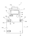
- FIG. 2 is a front view schematically showing the artificial heart-lung pump driving apparatus 1.
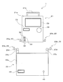
- FIG. 3 is a front view schematically showing a state where the module unit 21 and the base unit 22 are separated in the driving apparatus 1 for the artificial heart lung pump.
- the artificial heart-lung pump driving apparatus 1 includes a module unit 21 and a base unit 22.
- the module unit 21 is provided as a portable device that can be carried by an operator.
- the base unit 22 is provided as a device to which the module unit 21 is detachably connected. In the state shown in FIG. 2, the module unit 21 and the base unit 22 are electrically and mechanically connected. In the state shown in FIG. 3, the electrical connection and the mechanical connection between the module unit 21 and the base unit 22 are released.
- the module unit 21 and the base unit 22 are usually connected.
- the artificial heart-lung pump driving apparatus 1 is used in a situation where blood circulation assistance is required in an emergency such as in an ambulance, the artificial heart-lung pump driving apparatus 1 is used as a single module unit 21. . That is, the portable module unit 21 separated from the base unit 22 is carried to a place where it is used and used alone.
- the module main body 21a which is the main body of the module unit 21, is provided with a carrying handle 21b.
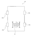
- FIG. 4 is a plan view of the base unit 22.
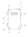
- FIG. 5 is a bottom view of the module unit 21.
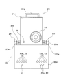
- FIG. 6 is a rear view of the artificial heart-lung pump driving apparatus 1 in a state where the module unit 21 and the base unit 22 are connected.
- the base unit 22 is provided with a module connection portion 44 that is electrically connected to the module unit 21.
- the module unit 21 is provided with a base connection portion 30 that is electrically connected to the base unit 22.
- the module connection portion 44 of the base unit 22 is electrically connected to the module unit 21 at the base connection portion 30.
- the base connection part 30 of the module unit 21 is electrically connected to the base unit 22 by the module connection part 44.
- the module connection portion 44 of the base unit 22 is provided on the upper surface side of the housing of the base main body 22a which is the main body of the base unit 22.
- the base connection portion 30 of the module unit 21 is provided on the lower surface side of the housing in the module main body 21 a of the module unit 21.
- planar pads 24 formed of an elastic member such as rubber are attached to the lower surface of the module main body 21a of the module unit 21 at a plurality of locations.
- both the base connection part 30 of the module unit 21 and the module connection part 44 of the base unit 22 are configured to include a plurality of connectors.
- the same number of connectors of the base connection unit 30 and the connectors of the module connection unit 44 are provided, and are configured to be connected correspondingly.
- one of the connector of the corresponding base connection part 30 and the connector of the module connection part 44 is configured as a plug-type connector, and the other is configured as a socket-type connector.
- both connectors are electrically connected by fitting each other.
- various signals described later are transmitted and received between the module unit 21 and the base unit 22 through the connection between the predetermined connector of the base connection unit 30 and the predetermined connector of the module connection unit 44.
- power is supplied from the base unit 22 to the module unit 21 through a connection between a predetermined connector of the base connection unit 30 and a predetermined connector of the module connection unit 44.
- the module connection portion 44 is provided so as to be slidable in a predetermined direction with respect to the casing of the base unit 22.
- the module connecting portion 44 is located along the front-rear direction of the base unit 22, which is the direction indicated by the arrow A, with respect to the casing of the base unit 22, that is, in front of the base unit 22 ( The form supported so that a slide movement is possible along the direction perpendicular
- the driving device 1 for the artificial heart lung pump when the module unit 21 is connected to the base unit 22, the position of the module connecting portion 44 is adjusted in the front-rear direction of the base unit 22, and the connection work is easily performed. It is configured as follows.
- the artificial heart-lung pump driving apparatus 1 is provided with a lock mechanism 23.
- the lock mechanism 23 is provided as a mechanism that locks and integrates one of the module unit 21 and the base unit 22 while the module unit 21 and the base unit 22 are connected. That is, the lock mechanism 23 mechanically couples the module unit 21 and the base unit 22 while fixing the other to one of the module unit 21 and the base unit 22 in a state where the module unit 21 and the base unit 22 are electrically connected. It is provided as a mechanism for maintaining the state.
- the lock mechanism 23 includes a module side lock portion 23 a provided in the module unit 21 and a base side lock portion 23 b provided in the base unit 22.
- a plurality of module side lock portions 23a and a plurality of base side lock portions 23b are provided, and the same number is provided.
- the lock mechanism 23 provided with four module side lock portions 23 a and four base side lock portions 23 b is illustrated.
- the module side lock portion 23a is provided one by one in the front-rear direction on the lower end side of each side surface of the module unit 21.
- Each module-side lock portion 23 a is provided so as to protrude toward both sides of the housing of the module unit 21.
- an engagement convex portion that can be engaged with each base-side lock portion 23b is provided on the tip side of each module-side lock portion 23a.
- the base side lock portion 23b is provided one by one in the front-rear direction at the edge portions on both sides of the upper surface of the base unit 22 casing.
- Each base-side lock portion 23b is provided with a support portion 23c and a swing connecting portion 23d (see FIG. 3).
- the support portion 23 c is fixed to the upper surface of the casing of the base unit 22.
- One end side of the swing connecting portion 23d is supported so as to be swingable in the rotation direction with respect to the support portion 23c, and the other end side is configured to be engaged and connected to the module side lock portion 23a.
- the base side lock portion 23b is provided with, for example, an engagement portion, a spring, and a spring release lever, which are not shown.
- the engaging portion is slidably provided at the support portion 23c, and is fixed by engaging the swing connecting portion 23d with the support portion 23c at a position where the swing connecting portion 23d engages with the module side lock portion 23a. It is provided as a member to do.
- the spring is provided as an elastic member that urges the engaging portion in a direction in which the swing coupling portion 23d is fixed to the support portion 23c.
- the spring release lever is provided as an operation unit that can be operated by an operator to release the urging force of the spring that urges the engaging portion in a direction to fix the swing coupling portion 23d to the support portion 23c. It has been.
- the operator swings the swing connecting portion 23d in the rotational direction with respect to the support portion 23c and engages the module side lock portion 23a.
- the engaging portion urged by the spring is fixed so that the swing coupling portion 23d cannot swing relative to the support portion 23c.
- This operation is performed on all the module side lock portions 23a and the base side lock portions 23b. Thereby, the engagement state of the module side lock part 23a and the base side lock part 23b is maintained, and the module unit 21 is locked to the base unit 22.
- FIG. 7 is a block diagram showing the artificial heart-lung pump driving apparatus 1 and devices connected to the artificial heart-lung pump driving apparatus 1.
- FIG. 8 is a block diagram showing the configuration of the module unit 21.
- the module unit 21 shown in FIGS. 2, 3, and 5 to 8 includes a motor 25, a motor driver 26, a control unit 27, a flow meter connection unit 28, a main display 29, the aforementioned base connection unit 30, and a module side battery 31.
- the motor 25 is configured as an electric motor that drives the heart-lung machine 12.
- the motor 25 is incorporated in the module main body 21a.
- the motor 25 may be provided separately from the module main body 21a and electrically connected to the module main body 21a via a cable.
- the motor 25 may be configured as a direct current motor or an alternating current motor.
- the motor 25 is incorporated in the module main body 21a with the joint portion 25a connected to the heart-lung machine pump exposed from the back surface of the module main body 21a (see FIG. 6).
- the motor 25 is provided with a drive magnet (not shown) that is magnetically coupled to a driven magnet incorporated in the heart-lung pump 12 by connecting the joint portion 25a to the heart-lung pump 12. Yes.
- the motor 25 is driven via the motor driver 26 based on a command signal from the control unit 27, thereby driving the heart-lung machine pump 12 via the magnetic coupling described above.
- Electrical energy for driving the motor 25 is supplied from the module side battery 31 via the power supply board 34 and the motor driver 26 when the module unit 21 is used alone.
- the electric energy for driving the motor 25 is transmitted from the base unit 22 via the base connection portion 30, the power supply board 34 and the motor driver 26. Supplied.
- the motor driver 26 drives the motor 25 based on a command signal from the control unit 27.
- the motor driver 26 controls the rotation speed (rotation speed) and torque current of the motor 25 based on a command signal from the control unit 27.
- the motor driver 26 is provided with an inverter.
- the control unit 27 is configured by a processor provided as a CPU (Central Processing Unit). And the control part 27 controls the motor 25 via the motor driver 26 based on the operation input of the command from the outside by the operator.
- the operation input of the command from the outside by the operator is performed by the operator rotating the motor operation dial 38 provided on the front side of the module main body 21a.
- the rotation speed of the motor 25 changes so as to increase, and the flow rate of blood sent to the tube 15c of the cardiopulmonary circuit 11 increases. Will do.
- the rotational speed of the motor 25 changes so as to be reduced, and the flow rate of blood sent to the tube 15c decreases. It will be.
- the control unit 27 is also configured to control display on the main display 29 and the sub display 33, control of the operation of the auto clamp 16, and the like.
- the flow meter connection unit 28 is configured as a communication port connected to the flow meter 17 so as to be able to receive the detection signal of the flow meter 17.
- a detection signal related to the blood flow detected by the flow meter 17 is input to the flow meter connection unit 28 as an analog signal.
- the detection signal as an analog signal is converted into a digital signal by an A / D conversion unit (analog / digital conversion unit) 35.
- the detection signal of the flow meter 17 converted into a digital signal by the A / D conversion unit 35 is input to the control unit 27.
- the main display 29 is provided as a display capable of displaying at least the blood flow detected by the flow meter 17, and constitutes a display unit of the present embodiment.
- the main display 29 is controlled to display a screen for displaying a blood flow rate and the like by a main display driver 36 that operates based on a command signal from the control unit 27.
- the operator can grasp the flow rate of blood circulating in the artificial heart-lung circuit 11 by checking the flow rate of blood displayed on the main display 29. Then, the operator operates the motor operation dial 38 while confirming the display on the main display 29, and adjusts the flow rate of the blood circulating through the heart-lung machine circuit 11 to a desired flow rate.
- the sub display 33 is provided as a display different from the main display 29 and constitutes a backup display unit of the present embodiment. That is, the sub-display 33 is provided as a backup display when a failure occurs in the main display 29. Further, the sub display 33 displays a screen even when the main display 29 is operating normally. Then, the sub display 33 displays, for example, a battery remaining amount that is a remaining amount of electric energy stored in the module-side battery 31.
- the sub display 33 is controlled by a sub display driver 37 that operates based on a command signal from the control unit 27 so as to display a screen for displaying the remaining battery level and the like.
- FIG. 9 is a front view showing the module unit 21, and is a diagram schematically illustrating a state in which screens are displayed on the main display 29 and the sub display 33.
- “4.3 L / min” is displayed as the blood flow rate
- a bar-shaped level display as an image display corresponding to the blood flow rate is displayed.
- a form in which “90%” is displayed as the remaining battery level is illustrated.
- the module unit 21 includes a timer (not shown). Based on the time measured by the timer, the control unit 27 controls the main display 29 or the sub display 33 to display the time or work. The time from the start may be displayed.
- the main display 29 is configured as a touch panel that can be pressed on the display, for example.
- the module unit 21 displays a screen to be displayed on the main display 29 based on the control of the control unit 27 and the main display driver 36 when an input operation by the operator is performed on the main display 29 as a touch panel. Switching is performed. Thereby, the operator can display a screen other than the screen for displaying the blood flow rate on the main display 29. For example, the operator performs an operation of switching the screen displayed on the main display 29, so that the controller 27 controls the control unit 27 based on the operation state of the motor 25, the state of the module battery 31, the detection signal of the flow meter 17, and the like. A screen for displaying the detected alarm signal or a screen for changing various settings of the module unit 21 can be confirmed.
- the module side battery 31 is built in the module main body 21a, and is configured as, for example, a lithium ion battery.
- the electric energy supplied from the base unit 22 to the base connection unit 30 is controlled by the power supply board 34 and stored in the module-side battery 31.
- the electric energy stored in the module-side battery 31 is supplied to the motor driver 26, the control unit 27, the A / D conversion unit 35, the main display 29, the sub display 33, the main display driver 36, and the sub display by the power supply board 34. Supplied to the driver 37 and the like.
- FIG. 8 the illustration of the electric energy supply path from the power supply board 34 to each of the above devices (26, 27, 29, 33, 35, 36, 37) is omitted.
- the storage device connection unit 32 is configured as a communication port to which the external storage device 39 is connected, and is provided as a USB (Universal Serial Bus) port, for example.
- a module unit 21 provided with a plurality of storage device connection sections 32 as USB ports is illustrated (see FIGS. 2, 3, and 9).
- the external storage device 39 is configured as a semiconductor memory such as a USB memory, for example.
- data relating to the blood flow detected by the flow meter 17 is stored in the external storage device 39 connected to the storage device connection unit 32 under the control of the control unit 27 based on the touch panel operation by the operator on the main display 29. Is done.
- FIG. 10 is a block diagram showing the configuration of the base unit 22.
- the base unit 22 shown in FIGS. 2 to 4, 6, 7, and 10 includes a power supply board 41, a switching power supply 42, a sensor connection portion 43, the module connection portion 44 described above, a base side battery 45, and an operation device connection portion. 46, a clamp connection unit 47, an A / D conversion unit 48, a display 49, a display driver 50, and the like.
- the switching power supply 42 and the power supply substrate 41 constitute a power supply circuit according to this embodiment that converts a current supplied from an AC power supply 40 that is an external power supply to supply to the device provided in the base unit 22 and the module unit 21. Yes.
- the switching power supply 42 is provided as a power supply circuit that converts an alternating current into a direct current.
- the power supply board 41 is provided as a power supply circuit that generates a current that flows at a voltage required for each device and module unit 21 provided in the base unit 22.
- the AC power supply 40 is configured as a power supply provided in the operating room. In a state in which the module unit 21 is connected to the base unit 22, the electrical energy in which the current and voltage are converted from alternating current to direct current by the switching power supply 42 is controlled via the module connection portion 44 by the control of the power supply substrate 41. To be supplied.
- the electric energy supplied from the AC power source 40 and converted from AC to DC by the switching power source 42 is supplied to the base unit 22 such as the A / D converter 48, the display 49, and the display driver 50 by the power supply substrate 41.
- the illustration of the electric energy supply path from the power supply board 41 to each of the devices (48, 49, 50) is omitted.
- the electric energy supplied from the AC power supply 40 and converted from AC to DC by the switching power supply 42 is also supplied to the base side battery 45 and stored in the base side battery 45 under the control of the power supply board 41.
- the base side battery 45 provided in the base unit 22 is built in the base main body 22a.
- the base side battery 45 is configured as a lead storage battery, for example.
- the base side battery 45 is provided as a backup power source for dealing with a case where a power failure occurs in the operating room and the function of the AC power source 45 is stopped.
- the AC power supply 45 stops functioning the electrical energy stored in the base-side battery 45 is supplied to each device of the module unit 21 and the base unit 22.
- the sensor connection unit 43 is connected to the thermometer 18, the level sensor 19, and the pressure gauge (pressure sensor) 51 so as to receive detection signals from the thermometer 18, the level sensor 19, and the pressure gauge. It is configured as a communication port.
- the pressure gauge 51 is not shown. However, as shown in FIG. 7, the pressure gauge 51 is connected to the heart-lung machine pump driving device 1. May be.
- the pressure gauge 51 is provided as a pressure sensor that detects the pressure of blood flowing through the artificial heart lung circuit 11.
- the pressure gauge 51 is connected to the tube 15c via the branch part 20, for example, and is comprised so that the pressure of the blood which flows through the tube 15c can be detected.
- the pressure gauge 51 is also provided as one of the sensors of the present embodiment that detects information related to blood in the heart-lung machine circuit 11. And the pressure gauge 51 detects the pressure of the blood in the heart-lung machine circuit 11 as information regarding the blood.
- thermometer sensor connection portion 43 As the sensor connection portion 43, a thermometer sensor connection portion 43a, a pressure gauge sensor connection portion 43b, and a level sensor sensor connection portion 43c are provided. A plurality of thermometer sensor connection portions 43a are provided, and FIG. 6 illustrates an example in which five channels are provided. Therefore, in this embodiment, five thermometers can be connected to the base unit 22. Then, when the thermometer 18 is connected to the thermometer sensor connection portion 43 a, a detection signal related to the blood temperature detected by the thermometer 18 is input to the base unit 22.
- FIG. 6 illustrates an example in which five channels are provided. Therefore, in the case of this form, five pressure gauges can be connected to the base unit 22. And the detection signal regarding the pressure of the blood detected with the pressure gauge 51 is input into the base unit 22 by connecting the pressure gauge 51 to the sensor connection part 43b for pressure gauges.
- the detection signal input from the sensor connection part 43a for thermometers and the detection signal input from the sensor connection part 43b for pressure gauges are input as an analog signal.
- These detection signals as analog signals are converted into digital signals by an A / D conversion unit (analog / digital conversion unit) 48.
- the detection signal of the thermometer 18 and the detection signal of the pressure gauge 51 converted into a digital signal by the A / D conversion unit 48 are transmitted to the module unit 21 via the module connection unit 44 and the base connection unit 30 connected to each other.
- the module unit 21 displays the blood temperature detected by the thermometer 18 and the blood pressure detected by the pressure gauge 51 on the main display 29 based on the input detection signals of the thermometer 18 and pressure gauge 51. It is also configured to be displayable.
- FIG. 6 illustrates an example in which two channels are provided. Therefore, in this embodiment, two level sensors can be connected to the base unit 22. Then, a detection signal relating to the liquid level of the blood storage tank 14 as an on / off signal detected by the level sensor 19 is input to the base unit 22. And the detection signal of the level sensor 19 is input into the control part 27 of the module unit 21 through the module connection part 44 and the base connection part 30 which were mutually connected. That is, the base unit 22 is configured to output the detection signal of the level sensor 19 to the module unit 21.
- the module unit 21 can display on the main display 29 whether there is a liquid level lowering abnormality that causes the liquid level of the blood storage tank 14 to be lower than a predetermined liquid level based on the input detection signal of the level sensor 19. It is also configured.
- the operation device connection unit 46 is configured as a communication port to which an external control panel 52, which is an external input operation device that performs command input operations, is connected.
- the external control panel 52 may be configured as various types of input operation devices.
- the external control panel 52 may be configured as an input operation device having a touch panel.
- the external control panel 52 may be configured as a personal computer provided with a keyboard, a pointing device, and the like as input devices.
- a command input to the base unit 22 from the external control panel 52 is input to the control unit 27 of the module unit 21 through the module connection unit 44 and the base connection unit 30 connected to each other.
- an operation based on a command input from the external control panel 52 is executed under the control of the control unit 27.
- the operator in a state where the external control panel 52 is connected to the operation device connection unit 46, the operator can perform an operation using the external control panel 52 in addition to the operation using the main display 29.
- the operation by the external control panel 52 may be prioritized over the operation by the main display 29.
- the clamp connection unit 47 is configured as a communication port connected to the auto clamp 16 so that a control signal for controlling the operation of the auto clamp 16 can be output from the base unit 22 to the auto clamp 16. And in the state where the auto clamp 16 is connected to the clamp connection part 47, when the control part 27 detects that air bubbles are mixed in the blood flowing through the tube 15d based on the detection result of the flow meter 17, The control signal for operating the auto clamp 16 is generated.
- the control unit 27 when the module unit 21 receives a bubble detection signal from the flow meter 17, the control unit 27 is disposed downstream of the flow meter 17 in the cardiopulmonary circuit 11 via the base unit 22.
- the auto clamp 16 is controlled so that the clamped auto clamp 16 performs the clamping operation. That is, the control unit 27 outputs a control signal for exciting the solenoid mechanism of the auto clamp 16 to the auto clamp 16 via the base connection unit 30, the module connection unit 44 and the clamp connection unit 47.
- the tube 15d is clamped by the auto clamp 16, and the flow of blood flowing through the tube 15d is regulated. As a result, air bubbles mixed in blood flowing through the tube 15d are prevented from being sent to the patient 100.
- the control unit 27 also operates the above-described control signal for operating the auto clamp 16 when it is detected based on the detection result of the level sensor 19 that the liquid level of the blood storage tank 14 is lower than a predetermined level. Is generated.
- an ON signal as a detection signal for detecting that the liquid level of the blood storage tank 14 is lower than a predetermined liquid level is output from the level sensor 19 to the base unit 22, this signal is The signal is input to the control unit 27 via the module connection unit 44 and the base connection unit 30. Then, the control unit 27 controls the auto clamp 16 via the base unit 22 so that the auto clamp 16 disposed on the downstream side of the blood storage tank 14 in the oxygenator circuit 11 performs a clamping operation. That is, the control unit 27 outputs a control signal for exciting the solenoid mechanism of the auto clamp 16 to the auto clamp 16 via the base connection unit 30, the module connection unit 44 and the clamp connection unit 47.
- the tube 15d is clamped by the auto clamp 16, and the flow of blood flowing through the tube 15d is regulated. As a result, even if bubbles are sucked into the tube 15b as the liquid level of the blood storage tank 14 is lowered, the bubbles are prevented from being sent to the patient 100.
- the display 49 is provided as a display for displaying the state of the device connected to the base unit 22. For example, detection results detected by the thermometer 18, the pressure gauge 51, and the level sensor 19 are displayed on the display 49 under the control of the display driver 50.
- the operating condition of the motor 25 for driving the heart-lung machine pump 12 is determined by the control unit 27 configured using a processor provided as a CPU based on an external operation. It is controlled via the driver 26. Then, the operator can adjust the operating condition of the motor 25 while confirming the flow rate of blood flowing through the heart-lung machine circuit 11 on the main display 29. Therefore, an artificial heart-lung pump driving apparatus 1 that is easy to handle is constructed.
- the module unit 21 includes a module-side battery 31.
- the module unit 21 is configured as a portable unit that can be carried by being disconnected from the base unit 22 after the connection between the base connection unit 30 and the module connection unit 44 is released.
- the module unit 21 can drive the artificial heart-lung pump 12 by driving the motor 25 alone. For this reason, according to the present embodiment, it is possible to construct the artificial heart-lung pump driving apparatus 1 that can realize a portable structure and can easily cope with a situation where blood circulation assistance is required in an emergency.
- the base unit 22 includes a switching power supply 42 and is configured to be connectable to the module unit 21 through an electrical connection between the module connection unit 44 and the base connection unit 30. For this reason, power can be supplied from the base unit 22 to the module unit 21.
- the heart-lung machine pump 12 can be driven by the motor 25 of the module unit 21 with the base unit 22 connected to the module unit 21 installed in the operating room. That is, the artificial heart-lung pump driving apparatus 1 can be used in the operating room.
- the base unit 22 receives detection signals from sensors (thermometer 18, level sensor 19, pressure gauge 51) that detect information related to blood in the heart-lung machine circuit 11, and outputs it to the module unit 21. For this reason, an operator who performs work in the operating room can grasp information related to blood in the heart-lung machine circuit 11.
- a drive unit 1 for an artificial heart lung pump can be provided.
- the base connection unit 30 and the module connection unit 44 are electrically connected in a state where the module unit 21 is mounted on the base unit 22. For this reason, the base unit 22 and the module unit 21 can be combined in a compact manner, and the arrangement space can be made more efficient in the operating room.
- the temperature of the blood in the heart-lung machine circuit 11 or the liquid level of the blood storage tank 14 is detected as information related to the blood in the heart-lung machine circuit 11, and the detected signal is used as the module unit. 21 is output. For this reason, an operator working in the operating room can grasp the temperature of the blood flowing through the artificial heart-lung circuit 11 or the liquid level of the blood storage tank 14.
- the module connecting portion 44 on the upper surface side of the base unit 22 and the base connecting portion 30 on the lower surface side of the module unit 21 in a state where the module unit 21 is mounted on the base unit 22. are electrically connected. For this reason, in the state which combined the base unit 22 and the module unit 21 mechanically, those electrical connections can also be completed. That is, it is possible to realize a form with excellent work efficiency that can achieve both mechanical connection and electrical connection of the base unit 22 and the module unit 21 by one or a series of connection operations. Moreover, the wiring for electrically connecting the base unit 22 and the module unit 21 can be omitted. Thereby, the wiring connection work can be reduced. Furthermore, it is possible to reduce the number of wirings arranged in the vicinity of the heart-lung machine pump drive device 1 and to prevent the wiring from interfering with the work or forming a dead space where the wiring is incapable of working. can do.
- the external storage device 39 can be connected to the module unit 21
- the information acquired by the module unit 21 can be stored and stored in the external storage device 39.
- the module unit 21 is further provided with the sub-display 33, so that even if a failure of the main display 29 occurs, the operator is required via the sub-display 33. Can grasp the information.
- the base side battery 45 is built in the base unit 22, even if a power failure occurs in the operating room, the electric energy stored in the base side battery 45 is used as a base. Power can be supplied from the unit 22 to the motor 25 of the module unit 21.
- the driving apparatus 1 for the heart-lung machine since the external control panel 52 that is an external input operation device can be connected to the base unit 22, when used in the operating room, the module unit 21 is used. Instead, it can be operated via the external control panel 52. For this reason, the artificial cardiopulmonary pump drive device 1 can be operated using an input operation device more suitable for operation in the operating room.
- the auto clamp 16 connected to the base unit 22 can be operated by the control of the control unit 27 of the module unit 21. Then, when it is detected that air bubbles are mixed in the blood flowing through the tube 15 d based on the detection result of the flow meter 17, the auto clamp 16 is activated, and the air bubbles in the tube 15 d enter the body of the patient 100. Can be prevented. For this reason, it is not necessary to construct a separate system for preventing air bubbles from entering the body of the patient 100. That is, it is not necessary to construct a system that includes a control device for controlling the operation of the auto clamp 16 based on the detection result of the flow meter 17 and is configured separately from the artificial heart lung pump drive device 1. Therefore, a configuration for preventing air bubbles from entering the body of the patient 100 can be constructed using the artificial heart lung pump driving device 1 and can be realized with a simpler configuration.
- the driving device 1 for the artificial heart lung pump when the decrease in the liquid level of the blood storage tank 14 is detected based on the detection result of the level sensor 19, the auto clamp 16 is controlled by the control unit 27 of the module unit 21. Can be activated.
- the artificial heart lung pump driving device 1 bubbles are sucked from the tube 15 b exposed at the upper part of the liquid level in the blood storage tank 14 as the liquid level lowers and enters the body of the patient 100. Can be prevented. For this reason, it is not necessary to construct a separate system for preventing air bubbles from entering the body of the patient 100.
- a configuration for preventing air bubbles from entering the body of the patient 100 can be constructed using the artificial heart lung pump driving device 1 and can be realized with a simpler configuration.
- the module unit 21 and the base unit 22 are connected to each other by the lock mechanism 23 while the module unit 21 and the base unit 22 are connected. Locked. For this reason, in a state where the base unit 22 and the module unit 21 are electrically connected, a stronger mechanical connection between them can be realized.
- a sensor for detecting information on blood in the heart-lung machine a sensor other than the temperature sensor and the level sensor is provided, and the heart-lung machine pump applied to the heart-lung machine without the temperature sensor and the level sensor.
- a drive device may be implemented.
- the configuration in which the base connection portion and the module connection portion are electrically connected in a state where the module unit is mounted on the base unit has been described as an example. Good.
- the base unit and the module unit are combined side by side in the horizontal direction instead of the vertical direction, that is, by combining the base unit and the module unit side by side in the front-rear or left-right direction, the base connection unit and the module connection unit are electrically connected.
- a connected form may be actually used.
- the configuration in which the module connection portion is provided on the upper surface side of the base unit and the base connection portion is provided on the lower surface side of the module unit has been described as an example.
- a mode in which a module connection portion is provided on the side surface of the base unit and a base connection portion is provided on the side surface of the module unit may be implemented.
- the present invention can be widely applied as an artificial heart lung pump drive device that is used in an artificial heart lung system and drives an artificial heart lung pump that circulates blood in an artificial heart lung circuit including an artificial lung.
Landscapes
- Health & Medical Sciences (AREA)
- Heart & Thoracic Surgery (AREA)
- Engineering & Computer Science (AREA)
- Cardiology (AREA)
- Veterinary Medicine (AREA)
- Public Health (AREA)
- Biomedical Technology (AREA)
- Hematology (AREA)
- Life Sciences & Earth Sciences (AREA)
- Animal Behavior & Ethology (AREA)
- General Health & Medical Sciences (AREA)
- Anesthesiology (AREA)
- Mechanical Engineering (AREA)
- Vascular Medicine (AREA)
- Pulmonology (AREA)
- Medical Informatics (AREA)
- Emergency Medicine (AREA)
- External Artificial Organs (AREA)
Abstract
取扱いが容易で、手術室での使用が可能であるとともに、可搬型構造も実現でき、緊急時の血液循環補助が必要な状況でも容易に対応することが可能な人工心肺ポンプ用駆動装置を提供する。 持ち運びが可能な可搬型のモジュールユニット21、モジュールユニット21が着脱可能に接続されるベースユニット22、を備える。モジュールユニット21は、人工心肺ポンプ12を駆動するモータ25、制御部27、流量計接続部28、血液の流量を表示する表示部29、ベースユニット22に電気的に接続されるベース接続部30、モジュール側バッテリ31を含む。ベースユニット22は、スイッチング電源42、血液に関する情報を検知するセンサ(18、19)に接続されるセンサ接続部43、モジュールユニット21に電気的に接続されるモジュール接続部44を含む。
Description
本発明は、人工心肺システムに用いられ、人工肺を含む人工心肺回路に血液を循環させる人工心肺ポンプを駆動する、人工心肺ポンプ用駆動装置に関する。
従来より、人工心肺システムにおいては、人工肺を含む人工心肺回路に血液を循環させる人工心肺ポンプを駆動する人工心肺ポンプ用駆動装置が用いられている。特許文献1乃至特許文献3においては、人工心肺システム或いは人工心肺システムに用いられる人工心肺ポンプ用駆動装置が開示されている。
特許文献1においては、完全携帯式の人工心肺システムが開示されている。この人工心肺システムは、緊急生命支援装置として病院外の環境で使用するための装置として構成されている。一方、特許文献2又は特許文献3に開示された人工心肺システムは、病院内の手術室にて使用するための装置として構成されている。
尚、特許文献2においては、手術室内に配置された人工心肺システムとともに用いられる電子データ監視兼データ評価装置が開示されている。この電子データ監視兼データ評価装置は、人工心肺システムとともに手術室に配置されるデータ監視兼データ記憶部分と、手術室とは異なる他の室に配置されるデータ評価部分とに分割されている。データ評価部分は、アクセスキーボード及び画面を有する一般のパーソナルコンピュータとして構成されている。人工心肺システムの運転中にデータ監視兼データ記憶部分にて取得されたデータは、可動データ記憶部分である記憶カードに記憶される。そして、記憶カードは、データ監視兼データ記憶部分から取り出され、手術室とは別室に配置されたデータ評価部分に接続されて用いられる。
また、特許文献3においては、人工心肺ポンプであるローラポンプ及び遠心ポンプの共用駆動装置として構成された人工心肺ポンプ用駆動装置が開示されている。この人工心肺ポンプ用駆動装置には、ローラポンプのモータ用プラグと遠心ポンプのモータ用プラグとを択一的に接続するモータ用コンセントと、モータ用コンセントに接続されたローラポンプ又は遠心ポンプのモータを制御するモータ制御部とが設けられている。
特許文献1に開示された人工心肺システムは、完全携帯式であり、救急車内等の緊急時の血液循環補助が必要な状況で使用することができる。しかしながら、特許文献1に開示された人工心肺システムに用いられる人工心肺ポンプ用駆動装置は、制御系がデジタル系ではなく、取扱いに習熟を要する。このため、緊急時の血液循環補助が必要な状況で使用することができるとともに、取扱いが容易な人工心肺ポンプ用駆動装置の実現が望まれる。
一方、特許文献2に開示された人工心肺システムに用いられる人工心肺ポンプ用駆動装置、及び特許文献3に開示された人工心肺ポンプ用駆動装置は、病院の手術室での使用が前提とされ、可搬型の構成ではない。よって、上記の人工心肺ポンプ用駆動装置は、救急車内等の緊急時の血液循環補助が必要な状況に対応することができない。このため、病院の手術室での使用が可能であるとともに、緊急時の血液循環補助が必要な状況での使用も可能な人工心肺ポンプ用駆動装置の実現が望まれる。
尚、特許文献2においては、データ評価装置が手術室の外部に配置可能な構成が開示されているが、緊急時に人工心肺システム自体を手術室以外で使用することを可能にする構成は開示されていない。また、特許文献3においては、ローラポンプ及び遠心ポンプのいずれも択一的に駆動可能な人工心肺ポンプ用駆動装置が開示されているが、緊急時に人工心肺システム自体を手術室以外で使用することを可能にする構成は開示されていない。
本発明は、上記実情に鑑みることにより、取扱いが容易で、手術室での使用が可能であるとともに、可搬型構造も実現でき、緊急時の血液循環補助が必要な状況でも容易に対応することが可能な人工心肺ポンプ用駆動装置を提供することを目的とする。
上記目的を達成するための第1発明に係る人工心肺ポンプ用駆動装置は、人工心肺システムに用いられ、人工肺を含む人工心肺回路に血液を循環させる人工心肺ポンプを駆動する、人工心肺ポンプ用駆動装置に関する。そして、第1発明に係る人工心肺ポンプ用駆動装置は、持ち運びが可能な可搬型のモジュールユニット、及び、前記モジュールユニットが着脱可能に接続されるベースユニット、を備えていることを特徴とする。更に、前記モジュールユニットは、当該モジュールユニットの本体であるモジュール本体に組み込まれ又は前記モジュール本体に接続されて前記人工心肺ポンプを駆動するモータと、外部からの指令の操作入力に基づいて、前記モータを制御する制御部と、前記人工心肺回路を流動する血液の流量を検知する流量計に対して当該流量計の検知信号を受信可能に接続される流量計接続部と、少なくとも前記流量計で検知された血液の流量を表示可能なディスプレイとして設けられた表示部と、前記ベースユニットに対して電気的に接続されるベース接続部と、前記モジュール本体に内蔵されるモジュール側バッテリと、を含むことを特徴とする。更に、前記ベースユニットは、外部電源から供給される電流を当該ベースユニットに設けられる機器及び前記モジュールユニットに供給するために変換する電源回路と、前記人工心肺回路中の血液に関する情報を検知する少なくとも一つのセンサに対して当該センサの検知信号を受信可能に接続されるセンサ接続部と、前記モジュールユニットに対して前記ベース接続部にて電気的に接続されるモジュール接続部と、を含むことを特徴とする。更に、前記ベースユニットは、前記センサの検知信号を前記モジュールユニットに対して出力することを特徴とする。
この構成によると、人工心肺ポンプを駆動するモータの運転条件は、外部からの操作に基づき、CPU等のプロセッサを用いて構成された制御部によって制御される。そして、操作者は、人工心肺回路を流動する血液の流量をディスプレイで確認しながら、モータの運転条件を調整することができる。よって、取り扱いが容易な人工心肺ポンプ用駆動装置が構築されることになる。
更に、モジュールユニットは、モジュール側バッテリが内蔵されている。また、モジュールユニットは、ベース接続部とモジュール接続部との接続が解除されてベースユニットから分離されることで、持ち運びが可能な可搬型のユニットとして構成されている。そして、モジュールユニットは、単体でモータを駆動して人工心肺ポンプを駆動することができる。このため、上記の構成によると、可搬型構造を実現でき、緊急時の血液循環補助が必要な状況でも容易に対応することが可能な人工心肺ポンプ用駆動装置を構築することができる。
また、ベースユニットは、電源回路が備えられ、モジュール接続部とベース接続部との電気的接続を介して、モジュールユニットに接続可能に構成されている。このため、ベースユニットからモジュールユニットに対して給電することができる。これにより、モジュールユニットが接続されたベースユニットを手術室内に設置した状態で、モジュールユニットのモータによって、人工心肺ポンプを駆動することができる。即ち、上記構成の人工心肺ポンプ用駆動装置は、手術室での使用も可能となる。更に、ベースユニットは、人工心肺回路中の血液に関する情報を検知するセンサの検知信号を受信してモジュールユニットに出力する。このため、手術室内で作業を行う操作者は、人工心肺回路中の血液に関する情報を把握することができる。
従って、上記の構成によると、取扱いが容易で、手術室での使用が可能であるとともに、可搬型構造も実現でき、緊急時の血液循環補助が必要な状況でも容易に対応することが可能な人工心肺ポンプ用駆動装置を提供することができる。
第2発明に係る人工心肺ポンプ用駆動装置は、第1発明の人工心肺ポンプ用駆動装置において、前記ベースユニットに前記モジュールユニットが搭載された状態で、前記ベース接続部と前記モジュール接続部とが電気的に接続されることを特徴とする。
この構成によると、ベースユニットにモジュールユニットが搭載された状態で、ベース接続部とモジュール接続部とが電気的に接続される。このため、ベースユニット及びモジュールユニットをコンパクトに組み合わせることができ、手術室内で配置スペースの効率化を図ることができる。
第3発明に係る人工心肺ポンプ用駆動装置は、第1発明又は第2発明の人工心肺ポンプ用駆動装置において、前記センサとして、前記人工心肺回路中の血液の温度を血液に関する情報として検知する温度センサ、及び、前記人工心肺回路に含まれる貯血タンクの液面レベルを前記人工心肺回路中の血液に関する情報として検知するレベルセンサ、の少なくともいずれかが、前記センサ接続部に接続されることを特徴とする。
この構成によると、人工心肺回路中の血液に関する情報として、人工心肺回路中の血液の温度或いは貯血タンクの液面レベルが検知され、その検知信号がモジュールユニットに出力される。このため、手術室内で作業を行う操作者は、人工心肺回路を流動する血液の温度或いは貯血タンクの液面レベルを把握することができる。
第4発明に係る人工心肺ポンプ用駆動装置は、第1発明乃至第3発明のいずれかの人工心肺ポンプ用駆動装置において、前記モジュールユニットに、外部記憶装置が接続される記憶装置接続部が更に設けられていることを特徴とする。
この構成によると、モジュールユニットに外部記憶装置を接続できるため、モジュールユニットにて取得された情報を外部記憶装置に記憶させて保存することができる。
第5発明に係る人工心肺ポンプ用駆動装置は、第1発明乃至第4発明のいずれかの人工心肺ポンプ用駆動装置において、前記モジュールユニットに、前記表示部とは異なるディスプレイとして設けられたバックアップ用表示部が更に設けられていることを特徴とする。
この構成によると、モジュールユニットにバックアップ用表示部が更に設けられるため、メインディスプレイとしての表示部の故障が発生した場合であっても、操作者は、バックアップ用表示部を介して必要な情報を把握することができる。
第6発明に係る人工心肺ポンプ用駆動装置は、第1発明乃至第5発明のいずれかの人工心肺ポンプ用駆動装置において、前記ベースユニットに、当該ベースユニットの本体であるベース本体に内蔵されるベース側バッテリが更に設けられていることを特徴とする。
この構成によると、ベースユニットにベース側バッテリが内蔵されるため、手術室の停電が生じた場合であっても、ベース側バッテリに蓄電した電気エネルギをベースユニットからモジュールユニットのモータに給電することができる。
第7発明に係る人工心肺ポンプ用駆動装置は、第1発明乃至第6発明のいずれかの人工心肺ポンプ用駆動装置において、前記ベースユニットに、指令の入力操作が行われる外部の入力操作装置が接続される操作装置接続部が更に設けられていることを特徴とする。
この構成によると、ベースユニットに外部の入力操作装置を接続することができるため、手術室で使用される際に、モジュールユニットを介してではなく、外部の入力操作装置を介して、操作することができる。このため、より手術室内での操作に適した入力操作装置を用いて人工心肺ポンプ用駆動装置を操作することができる。
第8発明に係る人工心肺ポンプ用駆動装置は、第1発明乃至第7発明のいずれかの人工心肺ポンプ用駆動装置において、前記ベースユニットに、前記人工心肺回路に含まれるチューブをクランプして血液の流動を規制可能なクランプ機構に対して当該クランプ機構の作動を制御する制御信号を出力可能に接続されるクランプ接続部が更に設けられ、前記流量計の検知結果に基づいて前記チューブを流動する血液に気泡が混入したことが検知されたときに、前記モジュールユニットの前記制御部が、前記制御信号を生成するとともに前記ベースユニットを介して前記クランプ機構を制御して血液の流動が規制されることを特徴とする。
この構成によると、ベースユニットに接続されたクランプ機構をモジュールユニットの制御部の制御によって作動させることができる。そして、流量計の検知結果に基づいてチューブを流動する血液に気泡が混入したことが検知されたときにクランプ機構を作動させ、チューブ中の気泡が患者の体内に侵入してしまうことを防止することができる。このため、患者の体内への気泡の侵入を防止するための別個のシステムを構築する必要がない。即ち、流量計の検知結果に基づいてクランプ機構の作動を制御するための制御装置を備え、人工心肺ポンプ用駆動装置とは別個に構成されるシステムを新たに構築する必要がない。よって、患者の体内への気泡の侵入を防止するための構成を、人工心肺ポンプ用駆動装置を利用して構築でき、より簡素な構成で実現することができる。
第9発明に係る人工心肺ポンプ用駆動装置は、第1発明乃至第8発明のいずれかの人工心肺ポンプ用駆動装置において、前記ベースユニットに、前記人工心肺回路に含まれるチューブをクランプして血液の流動を規制可能なクランプ機構に対して当該クランプ機構の作動を制御する制御信号を出力可能に接続されるクランプ接続部が更に設けられ、前記レベルセンサの検知結果に基づいて前記貯血タンクの液面レベルが所定のレベルよりも低下したことが検知されたときに、前記モジュールユニットの前記制御部が、前記制御信号を生成するとともに前記ベースユニットを介して前記クランプ機構を制御し、血液の流動が規制されることを特徴とする。
この構成によると、ベースユニットに接続されたクランプ機構をモジュールユニットの制御部の制御によって作動させることができる。そして、レベルセンサの検知結果に基づいて貯血タンクの液面レベルの低下が検知されたときにクランプ機構を作動させ、液面低下に伴って露出したチューブから気泡が吸い込まれて患者の体内に侵入してしまうことを防止することができる。このため、患者の体内への気泡の侵入を防止するための別個のシステムを構築する必要がない。即ち、レベルセンサの検知結果に基づいてクランプ機構の作動を制御するための制御装置を備え、人工心肺ポンプ用駆動装置とは別個に構成されるシステムを新たに構築する必要がない。よって、患者の体内への気泡の侵入を防止するための構成を、人工心肺ポンプ用駆動装置を利用して構築でき、より簡素な構成で実現することができる。
第10発明に係る人工心肺ポンプ用駆動装置は、第1発明乃至第9発明のいずれかの人工心肺ポンプ用駆動装置において、前記モジュールユニットと前記ベースユニットとが接続された状態で、前記モジュールユニット及び前記ベースユニットの一方に対して他方をロックして一体化するロック機構が更に設けられていることを特徴とする。
この構成によると、モジュールユニットとベースユニットとが接続された状態で、ロック機構により、モジュールユニット及びベースユニットの一方に他方が一体化されるようにロックされる。このため、ベースユニット及びモジュールユニットが電気的に接続された状態で、それらのより強固な機械的結合も実現できる。
本発明によると、取扱いが容易で、手術室での使用が可能であるとともに、可搬型構造も実現でき、緊急時の血液循環補助が必要な状況でも容易に対応することが可能な人工心肺ポンプ用駆動装置を提供することができる。
以下、本発明を実施するための形態について図面を参照しつつ説明する。尚、本発明は、人工心肺システムに用いられて人工肺を含む人工心肺回路に血液を循環させる人工心肺ポンプを駆動する人工心肺ポンプ用駆動装置として広く適用することができる。
[人工心肺システム概略]
図1は、本発明の一実施の形態に係る人工心肺ポンプ用駆動装置1が適用される人工心肺システム10の概略を示すブロック図である。本実施形態の人工心肺ポンプ用駆動装置1は、人工心肺システム10に用いられ、人工肺13を含む人工心肺回路11に血液を循環させる人工心肺ポンプ12を駆動する装置として構成される。
図1は、本発明の一実施の形態に係る人工心肺ポンプ用駆動装置1が適用される人工心肺システム10の概略を示すブロック図である。本実施形態の人工心肺ポンプ用駆動装置1は、人工心肺システム10に用いられ、人工肺13を含む人工心肺回路11に血液を循環させる人工心肺ポンプ12を駆動する装置として構成される。
人工心肺システム10は、本実施形態の人工心肺ポンプ用駆動装置1によって駆動される人工心肺ポンプ12、人工肺13、貯血タンク14、オートクランプ16、流量計17、温度計(温度センサ)18、レベルセンサ19、等を含んで構成されている。
人工心肺回路11は、チューブ(15a、15b、15c、15d)を含み、患者100と人工心肺システム10との間で血液を循環する血液循環回路として構成されている。そして、人工心肺回路11は、患者100、貯血タンク14、人工心肺ポンプ12、及び人工肺13が、閉ループを形成するようにチューブ(15a、15b、15c、15d)で接続されることで構成されている。
チューブ(15a、15b、15c、15d)は、可撓性を有する透明又は半透明な樹脂製のチューブとして設けられている。そして、チューブ15aは、患者100と貯血タンク14とを接続するように設置される。尚、チューブ15aは、患者100に対して、例えば、一方の大腿部の静脈側で接続される。チューブ15bは、貯血タンク14と人工心肺ポンプ12とを接続するように設置される。チューブ15cは、人工心肺ポンプ12と人工肺13とを接続するように設置される。チューブ15dは、人工肺13と患者100とを接続するように設置される。尚、チューブ15dは、患者100に対して、例えば、他方の大腿部の動脈側で接続される。また、図1において、チューブ(15a、15b、15c、15d)の矢印は、血液が人工心肺回路11を流動する方向を示している。
貯血タンク14は、患者100の静脈側から流出した血液を貯留するタンクとして設けられている。貯血タンク14内には、貯血タンク14内に貯留されている血液の液面レベルを検知するレベルセンサ19が設置されている。レベルセンサ19は、人工心肺回路11中の血液に関する情報を検知する本実施形態のセンサのうちの1つとして設けられている。そして、レベルセンサ19は、貯血タンク14の液面レベルを人工心肺回路11中の血液に関する情報として検知する。
レベルセンサ19は、例えば、所定の液面レベル以上であるか所定の液面レベル未満であるかを検知して、その検知信号をオンオフ信号として出力するセンサとして構成されている。例えば、レベルセンサ19は、貯血タンク14の液面レベルが所定の液面レベル未満であるときに検知信号としてのオン信号を出力し、貯血タンク14の液面レベルが所定の液面レベル以上であるときに検知信号としてのオフ信号を出力する。また、レベルセンサ19は、後述する人工心肺ポンプ用駆動装置1に対して、上記の検知信号を出力可能に接続されている。
人工心肺ポンプ12は、後述する人工心肺ポンプ用駆動装置1によって駆動される遠心血液ポンプとして構成されている。そして、チューブ15bに接続される入口ポート及びチューブ15cに接続される出口ポートを備えたハウジング(図示省略)と、ハウジング内で回転自在に支持されたインペラ(図示省略)とを備えて構成されている。インペラは、従動磁石を有し、人工心肺ポンプ用駆動装置1における後述するモータ25に取り付けられた駆動磁石との磁気結合により、モータ25の回転が伝達されるように構成されている。インペラが回転することで、人工心肺回路11を血液が循環することになる。
流量計17は、人工心肺回路11を流動する血液の流量を検知する流量計として設けられている。そして、本実施形態では、流量計17が、人工肺13と患者100とを接続するチューブ15dを流動する血液の流量を検知するように設置された形態が例示されている。流量計17は、例えば、チューブ15dに取り付けられてチューブ15dの外部からチューブ15d内を流動する血液の流量を検知する超音波式流量計として構成されている。流量計17は、後述する人工心肺ポンプ用駆動装置1に対して、流量計17の検知信号を出力可能に接続されている。
また、流量計17は、チューブ15dを流動する血液の流量を検知することに加え、チューブ15d内で超音波が散乱されたときに気泡の混入も検知するように構成されている。そして、流量計17は、人工心肺ポンプ用駆動装置1に対して、血液の流量が検知されているときにはその流量に関する検知信号を出力し、気泡の混入が検知されたときには、気泡検知信号を出力するように構成されている。
温度計18は、人工心肺回路11を流動する血液の温度を検知する温度センサとして設けられている。また、温度計18は、人工心肺回路11中の血液に関する情報を検知する本実施形態のセンサのうちの1つとして設けられている。そして、温度計18は、人工心肺回路11中の血液の温度を血液に関する情報として検知する。また、本実施形態では、温度計18が、チューブ15cを流動する血液の温度を検知するように設置された形態が例示されている。温度計18は、チューブ15cに対して分岐部20を介して接続され、チューブ15cを流動する血液の温度を検知可能に構成されている。温度計18は、後述する人工心肺ポンプ用駆動装置1に対して、温度計18の検知信号を出力可能に接続されている。
オートクランプ16は、人工心肺回路11のチューブをクランプして血液の流動を規制可能なクランプ機構として設けられている。即ち、オートクランプ16は、チューブを挟み込むように締め付けることで、チューブを流れる血液の流動を規制して阻止することが可能な機構として設けられている。そして、本実施形態では、オートクランプ16が、チューブ15dをクランプ可能なように設置された形態が例示されている。また、オートクランプ16は、チューブ15dに対して、流量計17による流量検知位置よりも血液流動方向における下流側に設置されている。
また、オートクランプ16は、例えば、互いに接近及び離間可能なようにスライド移動自在に支持された一対のクランプ部(16a、16b)、バネ、ソレノイド機構、等を備えて構成されている。そして、オートクランプ16は、例えば、バネによって互いに離間する方向に付勢されている一対のクランプ部(16a、16b)を、ソレノイド機構が励磁されることで、互いに接近させるように移動させる。これにより、オートクランプ16は、チューブをクランプするように構成されている。また、オートクランプ16は、後述する人工心肺ポンプ用駆動装置1に対して、人工心肺ポンプ用駆動装置1から入力される制御信号に基づいて作動するように、接続されている。
人工肺13は、患者100の呼吸機能を代行するためのガス交換部を備えて構成されている。そして、人工肺13は、チューブ15cから流入する血液に含まれる二酸化炭素ガスを取り出して外部に排出するとともに外部の酸素ガスを取り込んで血液中のガス交換を行い、この血液をチューブ15dから送出する。
[人工心肺ポンプ用駆動装置]
次に、本実施形態の人工心肺ポンプ用駆動装置1について説明する。図2は、人工心肺ポンプ用駆動装置1を模式的に示す正面図である。図3は、人工心肺ポンプ用駆動装置1におけるモジュールユニット21とベースユニット22とが分離した状態を模式的に示す正面図である。
次に、本実施形態の人工心肺ポンプ用駆動装置1について説明する。図2は、人工心肺ポンプ用駆動装置1を模式的に示す正面図である。図3は、人工心肺ポンプ用駆動装置1におけるモジュールユニット21とベースユニット22とが分離した状態を模式的に示す正面図である。
図2及び図3に示すように、人工心肺ポンプ用駆動装置1は、モジュールユニット21とベースユニット22とを備えて構成されている。モジュールユニット21は、操作者による持ち運びが可能な可搬型の装置として設けられている。ベースユニット22は、モジュールユニット21が着脱可能に接続される装置として設けられている。図2に示す状態では、モジュールユニット21とベースユニット22とが、電気的及び機械的に接続されている。そして、図3に示す状態では、モジュールユニット21とベースユニット22との電気的接続及び機械的接続が解除されている。
人工心肺ポンプ用駆動装置1は、病院の手術室にて人工心肺システム10に用いられて使用される場合は、通常、モジュールユニット21とベースユニット22とが接続された状態で、使用される。これに対し、人工心肺ポンプ用駆動装置1が救急車内等の緊急時の血液循環補助が必要な状況で使用される場合は、人工心肺ポンプ用駆動装置1は、モジュールユニット21単体で使用される。即ち、ベースユニット22から分離された可搬型のモジュールユニット21が、使用される場所まで持ち運びされ、単体で使用される。尚、モジュールユニット21の本体であるモジュール本体21aには、持ち運び用の取っ手21bが設けられている。
図4は、ベースユニット22の平面図である。図5は、モジュールユニット21の底面図である。図6は、モジュールユニット21とベースユニット22とが接続された状態の人工心肺ポンプ用駆動装置1の背面図である。
図4に示すように、ベースユニット22には、モジュールユニット21に対して電気的に接続されるモジュール接続部44が設けられている。一方、図5に示すように、モジュールユニット21には、ベースユニット22に対して電気的に接続されるベース接続部30が設けられている。ベースユニット22のモジュール接続部44は、モジュールユニット21に対してベース接続部30にて電気的に接続される。そして、モジュールユニット21のベース接続部30は、ベースユニット22に対してモジュール接続部44にて電気的に接続される。
ベースユニット22のモジュール接続部44は、ベースユニット22の本体であるベース本体22aにおける筐体の上面側に設けられている。一方、モジュールユニット21のベース接続部30は、モジュールユニット21のモジュール本体21aにおける筐体の下面側に設けられている。そして、図2及び図6に示すようにベースユニット22にモジュールユニット21が搭載された状態で、ベース接続部30とモジュール接続部44とが電気的に接続される。尚、モジュールユニット21のモジュール本体21aの下面には、複数個所に、ゴム等の弾性部材で形成された平面状のパッド24が取り付けられている。ベースユニット22にモジュールユニット21が搭載される際には、モジュール本体21aの下面とベース本体22aの上面との間で、複数のパッド24によって衝撃が吸収されることになる。
また、モジュールユニット21のベース接続部30とベースユニット22のモジュール接続部44とは、いずれも、複数のコネクタを備えて構成されている。ベース接続部30の各コネクタと、モジュール接続部44の各コネクタとは、同数設けられ、それぞれ対応して接続されるように構成されている。例えば、対応するベース接続部30のコネクタとモジュール接続部44のコネクタとのうちの一方が、プラグ形態のコネクタとして構成され、他方が、ソケット形態のコネクタとして構成される。そして、両コネクタは、互いに嵌合することで、電気的に接続される。
また、ベース接続部30の所定のコネクタとモジュール接続部44の所定のコネクタとの接続を介して、モジュールユニット21とベースユニット22との間において、後述する各種信号の送受信が行われる。また、ベース接続部30の所定のコネクタとモジュール接続部44の所定のコネクタとの接続を介して、ベースユニット22からモジュールユニット21への給電が行われる。
また、図4に示すように、モジュール接続部44は、ベースユニット22の筐体に対して、所定の方向にスライド移動可能に設けられている。尚、図4では、モジュール接続部44が、ベースユニット22の筐体に対して、矢印Aで示す方向であるベースユニット22の前後方向に沿って、即ち、ベースユニット22の正面(図2に示される面)及び背面(図6に示される面)に垂直な方向に沿って、スライド移動可能に支持された形態が例示されている。これにより、人工心肺ポンプ用駆動装置1では、モジュールユニット21がベースユニット22に接続される際に、モジュール接続部44の位置をベースユニット22の前後方向に調整し、容易に接続作業が行われるように構成されている。
また、人工心肺ポンプ用駆動装置1には、ロック機構23が設けられている。ロック機構23は、モジュールユニット21とベースユニット22とが接続された状態で、モジュールユニット21及びベースユニット22の一方に対して他方をロックして一体化する機構として設けられている。即ち、ロック機構23は、モジュールユニット21とベースユニット22とが電気的に接続された状態で、モジュールユニット21及びベースユニット22の一方に対して他方を固定して両者を機械的に結合させた状態を維持する機構として設けられている。
ロック機構23は、モジュールユニット21に設けられたモジュール側ロック部23aと、ベースユニット22に設けられたベース側ロック部23bとで構成されている。本実施形態では、モジュール側ロック部23aとベース側ロック部23bとが、それぞれ複数設けられるとともに同数設けられている。尚、図4及び図5に示すように、本実施形態では、モジュール側ロック部23a及びベース側ロック部23bが、それぞれ4つ設けられたロック機構23を例示している。
モジュール側ロック部23aは、モジュールユニット21の筐体の両側面のそれぞれの下端側において前後方向に1つずつ設けられている。そして、各モジュール側ロック部23aは、モジュールユニット21の筐体の両側方に向かって突出するように設けられている。更に、各モジュール側ロック部23aの先端側には、各ベース側ロック部23bに係合可能な係合凸部が設けられている。
ベース側ロック部23bは、ベースユニット22の筐体の上面における両側方の縁部分において前後方向に1つずつ設けられている。そして、各ベース側ロック部23bには、支持部23cと揺動連結部23dとが設けられている(図3を参照)。支持部23cは、ベースユニット22の筐体の上面に固定されている。揺動連結部23dは、その一端側が支持部23cに対して回転方向において揺動自在に支持され、その他端側がモジュール側ロック部23aに対して係合して連結されるように構成されている。
ベース側ロック部23bには、例えば、図示が省略された係合部、バネ、及びバネ解除レバーが設けられている。係合部は、支持部23cにおいてスライド移動自在に設けられ、揺動連結部23dがモジュール側ロック部23aに係合する位置で揺動連結部23dを支持部23cに対して係合させて固定する部材として設けられている。バネは、揺動連結部23dを支持部23cに固定させる方向に係合部を付勢する弾性部材として設けられている。バネ解除レバーは、操作者によって操作されることで、揺動連結部23dを支持部23cに固定させる方向に係合部を付勢するバネの付勢力を解除する操作が可能な操作部として設けられている。
ベースユニット22にモジュールユニット21をロックして固定する場合は、操作者は、揺動連結部23dを支持部23cに対して回転方向に揺動させてモジュール側ロック部23aに係合させる。この状態で、上記のバネによって付勢された上記の係合部が、支持部23cに対して揺動連結部23dが揺動不能となるように固定する。この操作が、全てのモジュール側ロック部23a及びベース側ロック部23bに対して行われる。これにより、モジュール側ロック部23aとベース側ロック部23bとの係合状態が維持され、モジュールユニット21がベースユニット22に対してロックされる。
一方、ベースユニット22とモジュールユニット21とのロックを解除する場合は、操作者は、上記のバネ解除レバーを操作し、係合部を付勢するバネの付勢力を解除した状態で、揺動連結部23dを支持部23cに対して回転方向に揺動させる。この結果、モジュール側ロック部23aとベース側ロック部23bとの係合が解除される。この操作が、全てのモジュール側ロック部23a及びベース側ロック部23bに対して行われる。これにより、モジュールユニット21とベースユニット22とのロックが解除され、ベースユニット22に対してモジュールユニット21を分離して持ち運びを行うことが可能となる。
[モジュールユニット]
次に、モジュールユニット21について、更に詳細に説明する。図7は、人工心肺ポンプ用駆動装置1と人工心肺ポンプ用駆動装置1に接続される機器とを示すブロック図である。図8は、モジュールユニット21の構成を示すブロック図である。図2、図3、図5~図8に示すモジュールユニット21は、モータ25、モータドライバ26、制御部27、流量計接続部28、メインディスプレイ29、前述のベース接続部30、モジュール側バッテリ31、記憶装置接続部32、サブディスプレイ33、電源基板34、A/D変換部35、メイン表示用ドライバ36、サブ表示用ドライバ37、等を備えて構成されている。
次に、モジュールユニット21について、更に詳細に説明する。図7は、人工心肺ポンプ用駆動装置1と人工心肺ポンプ用駆動装置1に接続される機器とを示すブロック図である。図8は、モジュールユニット21の構成を示すブロック図である。図2、図3、図5~図8に示すモジュールユニット21は、モータ25、モータドライバ26、制御部27、流量計接続部28、メインディスプレイ29、前述のベース接続部30、モジュール側バッテリ31、記憶装置接続部32、サブディスプレイ33、電源基板34、A/D変換部35、メイン表示用ドライバ36、サブ表示用ドライバ37、等を備えて構成されている。
モータ25は、人工心肺ポンプ12を駆動する電動モータとして構成されている。そして、モータ25は、本実施形態では、モジュール本体21aに組み込まれている。尚、モータ25は、モジュール本体21aとは別体に設けられて、モジュール本体21aに対してケーブルを介して電気的に接続されてもよい。また、モータ25は、直流モータとして構成されてもよく、交流モータとして構成されてもよい。
モータ25は、人工心肺ポンプに連結されるジョイント部25aがモジュール本体21aの背面から露出した状態で、モジュール本体21aに組み込まれている(図6を参照)。そして、モータ25には、ジョイント部25aが人工心肺ポンプ12に連結されることで、人工心肺ポンプ12に組み込まれた従動磁石に対して磁気結合される駆動磁石(図示省略)が、設けられている。モータ25は、制御部27からの指令信号に基づいてモータドライバ26を介して駆動されることで、上記の磁気結合を介して、人工心肺ポンプ12を駆動する。
モータ25を駆動するための電気エネルギは、モジュールユニット21が単体で使用される場合には、モジュール側バッテリ31から電源基板34及びモータドライバ26を介して供給される。一方、モジュールユニット21がベースユニット22に接続されて使用される場合には、モータ25を駆動するための電気エネルギは、ベースユニット22からベース接続部30、電源基板34及びモータドライバ26を介して供給される。
モータドライバ26は、制御部27からの指令信号に基づいて、モータ25を駆動する。例えば、モータドライバ26は、制御部27からの指令信号に基づいて、モータ25の回転速度(回転数)及びトルク電流を制御する。尚、モータ25が交流モータの場合には、モータドライバ26には、インバータが設けられる。
制御部27は、CPU(Central Processing Unit)として設けられたプロセッサにより構成されている。そして、制御部27は、操作者による外部からの指令の操作入力に基づいて、モータドライバ26を介してモータ25を制御する。操作者による外部からの指令の操作入力は、操作者がモジュール本体21aの正面側に設けられたモータ操作ダイヤル38を回転操作することで行われる。
例えば、操作者によってモータ操作ダイヤル38が所定の方向に回されることで、モータ25の回転速度が増速されるように変化し、人工心肺回路11のチューブ15cに送り出される血液の流量が増加することになる。一方、操作者によってモータ操作ダイヤル38が上記の所定の方向と反対方向に回されることで、モータ25の回転速度が減速されるように変化し、チューブ15cに送り出される血液の流量が減少することになる。
また、制御部27は、メインディスプレイ29及びサブディスプレイ33の表示の制御、オートクランプ16の作動の制御、等も行うように構成されている。
流量計接続部28は、流量計17に対して流量計17の検知信号を受信可能に接続される通信ポートとして構成されている。流量計17にて検知された血液の流量に関する検知信号は、アナログ信号として流量計接続部28に入力される。そして、このアナログ信号としての検知信号が、A/D変換部(アナログデジタル変換部)35にてデジタル信号に変換される。A/D変換部35にてデジタル信号に変換された流量計17の検知信号は、制御部27に入力される。
メインディスプレイ29は、少なくとも流量計17で検知された血液の流量を表示可能なディスプレイとして設けられ、本実施形態の表示部を構成している。メインディスプレイ29は、制御部27からの指令信号に基づいて作動するメイン表示用ドライバ36によって、血液の流量等を表示する画面を表示するように制御される。操作者は、メインディスプレイ29に表示された血液の流量を確認することで、人工心肺回路11を循環する血液の流量を把握することができる。そして、操作者は、メインディスプレイ29の表示を確認しながら、モータ操作ダイヤル38を操作し、人工心肺回路11を循環する血液の流量が所望の流量となるように調整する。
サブディスプレイ33は、メインディスプレイ29とは異なるディスプレイとして設けられ、本実施形態のバックアップ用表示部を構成している。即ち、サブディスプレイ33は、メインディスプレイ29に故障が発生した場合のバックアップ用のディスプレイとして設けられている。また、サブディスプレイ33は、メインディスプレイ29が正常に作動している場合も、画面を表示する。そして、サブディスプレイ33は、例えば、モジュール側バッテリ31に蓄電されている電気エネルギーの残量であるバッテリ残量を表示する。また、サブディスプレイ33は、制御部27からの指令信号に基づいて作動するサブ表示用ドライバ37によって、バッテリ残量等を表示する画面を表示するように制御される。
図9は、モジュールユニット21を示す正面図であって、メインディスプレイ29及びサブディスプレイ33に画面が表示された状態を模式的に例示する図である。図9に示すメインディスプレイ29では、血液の流量として「4.3L/min」が表示され、その血液の流量に対応するイメージ表示としてのバー状のレベル表示が表示された形態が例示されている。また、図9に示すサブディスプレイ33では、バッテリ残量として「90%」が表示された形態が例示されている。尚、モジュールユニット21には、図示が省略されたタイマが内蔵されており、このタイマで計測される時間に基づいて、制御部27の制御によって、メインディスプレイ29或いはサブディスプレイ33に、時刻或いは作業開始からの時間が表示されてもよい。
また、メインディスプレイ29は、例えば、ディスプレイ上での押圧操作が可能なタッチパネルとして構成されている。そして、モジュールユニット21は、タッチパネルとしてのメインディスプレイ29に対して操作者による入力操作が行われた場合に、制御部27及びメイン表示用ドライバ36の制御に基づいて、メインディスプレイ29に表示させる画面の切り替え等が行われるように構成されている。これにより、操作者は、メインディスプレイ29に血液の流量を表示する画面以外の画面を表示させることができる。例えば、操作者は、メインディスプレイ29に表示される画面を切り替える操作を行うことで、モータ25の運転状態、モジュール側バッテリ31の状態、流量計17の検知信号、等に基づいて制御部27にて検知されたアラーム信号を表示させるための画面、或いは、モジュールユニット21の各種設定を変更するための画面、等を確認することができる。
モジュール側バッテリ31は、モジュール本体21aに内蔵され、例えば、リチウムイオン電池として構成されている。モジュールユニット21がベースユニット22に接続された状態で、ベースユニット22からベース接続部30に給電された電気エネルギが、電源基板34によって制御され、モジュール側バッテリ31に蓄電される。そして、モジュール側バッテリ31に蓄電された電気エネルギは、電源基板34によって、モータドライバ26、制御部27、A/D変換部35、メインディスプレイ29、サブディスプレイ33、メイン表示用ドライバ36、サブ表示用ドライバ37、等に対して供給される。尚、図8では、電源基板34から上記の各機器(26、27、29、33、35、36、37)への電気エネルギの供給経路の図示が省略されている。
記憶装置接続部32は、外部記憶装置39が接続される通信ポートとして構成され、例えば、USB(Universal Serial Bus)ポートとして設けられている。本実施形態では、USBポートとしての記憶装置接続部32が複数設けられたモジュールユニット21が例示されている(図2、図3、図9を参照)。また、外部記憶装置39は、例えば、USBメモリ等の半導体メモリとして構成されている。例えば、流量計17で検知された血液の流量に関するデータは、メインディスプレイ29での操作者によるタッチパネル操作に基づく制御部27の制御によって、記憶装置接続部32に接続された外部記憶装置39に記憶される。
[ベースユニット]
次に、ベースユニット22について更に説明する。図10は、ベースユニット22の構成を示すブロック図である。図2~図4、図6、図7、図10に示すベースユニット22は、電源基板41、スイッチング電源42、センサ接続部43、前述のモジュール接続部44、ベース側バッテリ45、操作装置接続部46、クランプ接続部47、A/D変換部48、ディスプレイ49、表示用ドライバ50、等を備えて構成されている。
次に、ベースユニット22について更に説明する。図10は、ベースユニット22の構成を示すブロック図である。図2~図4、図6、図7、図10に示すベースユニット22は、電源基板41、スイッチング電源42、センサ接続部43、前述のモジュール接続部44、ベース側バッテリ45、操作装置接続部46、クランプ接続部47、A/D変換部48、ディスプレイ49、表示用ドライバ50、等を備えて構成されている。
スイッチング電源42及び電源基板41は、外部電源である交流電源40から供給される電流をベースユニット22に設けられる機器及びモジュールユニット21に供給するために変換する本実施形態の電源回路を構成している。そして、本実施形態では、スイッチング電源42は、交流の電流を直流の電流に変換する電源回路として設けられている。一方、電源基板41は、ベースユニット22に設けられる各機器及びモジュールユニット21にて必要となる電圧で流れる電流を生成する電源回路として設けられている。尚、交流電源40は、手術室に設けられた電源として構成されている。ベースユニット22にモジュールユニット21が接続された状態では、スイッチング電源42によって電流及び電圧が交流から直流に変換された電気エネルギは、電源基板41の制御によって、モジュール接続部44を介してモジュールユニット21に供給される。
また、交流電源40から供給されてスイッチング電源42にて交流から直流に変換された電気エネルギは、電源基板41によって、A/D変換部48、ディスプレイ49、表示用ドライバ50、等のベースユニット22に設けられる機器に対して供給される。尚、図10では、電源基板41から上記の各機器(48、49、50)への電気エネルギの供給経路の図示が省略されている。
また、交流電源40から供給されてスイッチング電源42にて交流から直流に変換された電気エネルギは、電源基板41の制御によって、ベース側バッテリ45に対しても給電され、ベース側バッテリ45に蓄電される。ベースユニット22に設けられるベース側バッテリ45は、ベース本体22aに内蔵されている。ベース側バッテリ45は、例えば、鉛蓄電池として構成されている。このベース側バッテリ45は、手術室の停電が生じて交流電源45の機能が停止した場合に対応するためのバックアップ電源として設けられている。交流電源45の機能停止が発生した場合には、ベース側バッテリ45に蓄電された電気エネルギが、モジュールユニット21及びベースユニット22の各機器に対して供給される。
センサ接続部43は、本実施形態では、温度計18、レベルセンサ19、圧力計(圧力センサ)51に対して、温度計18、レベルセンサ19、圧力計の検知信号を受信可能に接続される通信ポートとして構成されている。尚、図1に示す人工心肺システム10においては、圧力計51の図示が省略されているが、図7に示すように、圧力計51が人工心肺ポンプ用駆動装置1に接続される形態が実施されてもよい。圧力計51は、人工心肺回路11を流動する血液の圧力を検知する圧力センサとして設けられている。そして、圧力計51は、例えば、チューブ15cに対して分岐部20を介して接続され、チューブ15cを流動する血液の圧力を検知可能に構成されている。尚、本実施形態では、温度計18及びレベルセンサ19に加え、圧力計51も、人工心肺回路11中の血液に関する情報を検知する本実施形態のセンサのうちの1つとして設けられている。そして、圧力計51は、人工心肺回路11中の血液の圧力を血液に関する情報として検知する。
センサ接続部43としては、温度計用センサ接続部43a、圧力計用センサ接続部43b、レベルセンサ用センサ接続部43cが設けられている。温度計用センサ接続部43aは、複数設けられ、図6では、5チャンネル設けられた形態が例示されている。よって、この形態の場合、5つの温度計をベースユニット22に接続することができる。そして、温度計18が温度計用センサ接続部43aに接続されることで、温度計18で検知された血液の温度に関する検知信号が、ベースユニット22に入力される。
圧力計用センサ接続部43bは、複数設けられ、図6では、5チャンネル設けられた形態が例示されている。よって、この形態の場合、5つの圧力計をベースユニット22に接続することができる。そして、圧力計51が圧力計用センサ接続部43bに接続されることで、圧力計51で検知された血液の圧力に関する検知信号が、ベースユニット22に入力される。
尚、温度計用センサ接続部43aから入力される検知信号、及び圧力計用センサ接続部43bから入力される検知信号は、アナログ信号として入力される。そして、これらのアナログ信号としての検知信号は、A/D変換部(アナログデジタル変換部)48にてデジタル信号に変換される。A/D変換部48にてデジタル信号に変換された温度計18の検知信号及び圧力計51の検知信号は、互いに接続されたモジュール接続部44及びベース接続部30を介して、モジュールユニット21の制御部27に入力される。即ち、ベースユニット22は、温度計18の検知信号及び圧力計51の検知信号をモジュールユニット21に対して出力するように構成されている。尚、モジュールユニット21は、入力された温度計18及び圧力計51の検知信号に基づいて、メインディスプレイ29に温度計18で検知された血液の温度及び圧力計51で検知された血液の圧力を表示可能にも構成されている。
レベルセンサ用接続部43cは、複数設けられ、図6では、2チャンネル設けられた形態が例示されている。よって、この形態の場合、2つのレベルセンサをベースユニット22に接続することができる。そして、レベルセンサ19で検知されたオンオフ信号としての貯血タンク14の液面レベルに関する検知信号が、ベースユニット22に入力される。そして、レベルセンサ19の検知信号は、互いに接続されたモジュール接続部44及びベース接続部30を介して、モジュールユニット21の制御部27に入力される。即ち、ベースユニット22は、レベルセンサ19の検知信号をモジュールユニット21に対して出力するように構成されている。尚、モジュールユニット21は、入力されたレベルセンサ19の検知信号に基づいて、貯血タンク14の液面レベルが所定の液面レベル未満となる液面レベル低下異常の有無をメインディスプレイ29に表示可能にも構成されている。
操作装置接続部46は、指令の入力操作が行われる外部の入力操作装置である外部コントロールパネル52が接続される通信ポートとして構成されている。外部コントロールパネル52は、種々の形態の入力操作装置として構成されていてもよい。例えば、外部コントロールパネル52は、タッチパネルを有する入力操作装置として構成されていてもよい。また、外部コントロールパネル52は、入力機器としてのキーボード、ポインティングデバイス、等が設けられたパーソナルコンピュータとして構成されていてもよい。
また、外部コントロールパネル52からベースユニット22に入力された指令は、互いに接続されたモジュール接続部44及びベース接続部30を介して、モジュールユニット21の制御部27に入力される。そして、モジュールユニット21では、制御部27の制御によって、外部コントロールパネル52から入力された指令に基づいた操作が実行される。このように、外部コントロールパネル52が操作装置接続部46に接続されている状態では、操作者は、メインディスプレイ29による操作に加えて、外部コントロールパネル52による操作も行うことができる。尚、外部コントロールパネル52が操作装置接続部46に接続されている状態では、メインディスプレイ29による操作よりも外部コントロールパネル52による操作が優先されるように構成されていてもよい。
クランプ接続部47は、ベースユニット22からオートクランプ16にこのオートクランプ16の作動を制御する制御信号を出力可能にオートクランプ16に対して接続される通信ポートとして構成されている。そして、クランプ接続部47にオートクランプ16が接続された状態では、制御部27は、流量計17の検知結果に基づいてチューブ15dを流動する血液に気泡が混入したことが検知されたときに、オートクランプ16を作動させる上記の制御信号を生成する。
より詳細には、モジュールユニット21にて流量計17からの気泡検知信号が受信されたときには、制御部27は、ベースユニット22を介して、人工心肺回路11において流量計17よりも下流側に配置されたオートクランプ16がクランプ動作を行うように、オートクランプ16を制御する。即ち、制御部27は、ベース接続部30、モジュール接続部44及びクランプ接続部47を介して、オートクランプ16に対して、オートクランプ16のソレノイド機構を励磁させる制御信号を出力する。
上記により、チューブ15dがオートクランプ16によってクランプされ、チューブ15dを流動する血液の流動が規制される。この結果、チューブ15dを流動する血液に混入した気泡が患者100に送られてしまうことが防止される。
また、制御部27は、レベルセンサ19の検知結果に基づいて貯血タンク14の液面レベルが所定のレベルよりも低下したことが検知されたときにも、オートクランプ16を作動させる上記の制御信号を生成する。
より詳細には、レベルセンサ19から、貯血タンク14の液面レベルが所定の液面レベル未満であることを検知する検知信号としてのオン信号が、ベースユニット22に出力されたときには、この信号が、モジュール接続部44及びベース接続部30を介して、制御部27に入力される。そして、制御部27は、ベースユニット22を介して、人工心肺回路11において貯血タンク14よりも下流側に配置されたオートクランプ16がクランプ動作を行うように、オートクランプ16を制御する。即ち、制御部27は、ベース接続部30、モジュール接続部44及びクランプ接続部47を介して、オートクランプ16に対して、オートクランプ16のソレノイド機構を励磁させる制御信号を出力する。
上記により、チューブ15dがオートクランプ16によってクランプされ、チューブ15dを流動する血液の流動が規制される。この結果、貯血タンク14の液面レベルの低下に伴ってチューブ15bに気泡が吸い込まれてしまった場合であっても、その気泡が患者100に送られてしまうことが防止される。
ディスプレイ49は、ベースユニット22に接続された機器の状態を表示するディスプレイとして設けられている。例えば、温度計18、圧力計51、レベルセンサ19によって検知された検知結果が、表示用ドライバ50の制御によって、ディスプレイ49に表示される。
[人工心肺ポンプ用駆動装置の作用効果]
以上説明したように、本実施形態によると、人工心肺ポンプ12を駆動するモータ25の運転条件は、外部からの操作に基づき、CPUとして設けられたプロセッサを用いて構成された制御部27によってモータドライバ26を介して制御される。そして、操作者は、人工心肺回路11を流動する血液の流量をメインディスプレイ29で確認しながら、モータ25の運転条件を調整することができる。よって、取り扱いが容易な人工心肺ポンプ用駆動装置1が構築されることになる。
以上説明したように、本実施形態によると、人工心肺ポンプ12を駆動するモータ25の運転条件は、外部からの操作に基づき、CPUとして設けられたプロセッサを用いて構成された制御部27によってモータドライバ26を介して制御される。そして、操作者は、人工心肺回路11を流動する血液の流量をメインディスプレイ29で確認しながら、モータ25の運転条件を調整することができる。よって、取り扱いが容易な人工心肺ポンプ用駆動装置1が構築されることになる。
更に、モジュールユニット21は、モジュール側バッテリ31が内蔵されている。また、モジュールユニット21は、ベース接続部30とモジュール接続部44との接続が解除されてベースユニット22から分離されることで、持ち運びが可能な可搬型のユニットとして構成されている。そして、モジュールユニット21は、単体でモータ25を駆動して人工心肺ポンプ12を駆動することができる。このため、本実施形態によると、可搬型構造を実現でき、緊急時の血液循環補助が必要な状況でも容易に対応することが可能な人工心肺ポンプ用駆動装置1を構築することができる。
また、ベースユニット22は、スイッチング電源42が備えられ、モジュール接続部44とベース接続部30との電気的接続を介して、モジュールユニット21に接続可能に構成されている。このため、ベースユニット22からモジュールユニット21に対して給電することができる。これにより、モジュールユニット21が接続されたベースユニット22を手術室内に設置した状態で、モジュールユニット21のモータ25によって、人工心肺ポンプ12を駆動することができる。即ち、人工心肺ポンプ用駆動装置1は、手術室での使用も可能となる。更に、ベースユニット22は、人工心肺回路11中の血液に関する情報を検知するセンサ(温度計18、レベルセンサ19、圧力計51)の検知信号を受信してモジュールユニット21に出力する。このため、手術室内で作業を行う操作者は、人工心肺回路11中の血液に関する情報を把握することができる。
従って、本実施形態によると、取扱いが容易で、手術室での使用が可能であるとともに、可搬型構造も実現でき、緊急時の血液循環補助が必要な状況でも容易に対応することが可能な人工心肺ポンプ用駆動装置1を提供することができる。
また、人工心肺ポンプ用駆動装置1によると、ベースユニット22にモジュールユニット21が搭載された状態で、ベース接続部30とモジュール接続部44とが電気的に接続される。このため、ベースユニット22及びモジュールユニット21をコンパクトに組み合わせることができ、手術室内で配置スペースの効率化を図ることができる。
また、人工心肺ポンプ用駆動装置1によると、人工心肺回路11中の血液に関する情報として、人工心肺回路11中の血液の温度或いは貯血タンク14の液面レベルが検知され、その検知信号がモジュールユニット21に出力される。このため、手術室内で作業を行う操作者は、人工心肺回路11を流動する血液の温度或いは貯血タンク14の液面レベルを把握することができる。
また、人工心肺ポンプ用駆動装置1によると、ベースユニット22にモジュールユニット21が搭載された状態で、ベースユニット22の上面側のモジュール接続部44とモジュールユニット21の下面側のベース接続部30とが電気的に接続される。このため、ベースユニット22とモジュールユニット21とが機械的に組み合わされた状態でそれらの電気的接続も完成することができる。即ち、ベースユニット22及びモジュールユニット21の機械的接続と電気的接続とを1回の又は一連の接続動作で両立することができる作業効率の優れた形態を実現することができる。また、ベースユニット22とモジュールユニット21とを電気的に接続するための配線を省略することができる。これにより、配線接続作業の削減を図ることができる。更に、人工心肺ポンプ用駆動装置1の近傍に配置される配線の削減を図ることができ、配線が作業の妨げとなり或いは配線が作業の不能な領域であるデッドスペースを形成してしまうことを抑制することができる。
また、人工心肺ポンプ用駆動装置1によると、モジュールユニット21に外部記憶装置39を接続できるため、モジュールユニット21にて取得された情報を外部記憶装置39に記憶させて保存することができる。
また、人工心肺ポンプ用駆動装置1によると、モジュールユニット21にサブディスプレイ33が更に設けられるため、メインディスプレイ29の故障が発生した場合であっても、操作者は、サブディスプレイ33を介して必要な情報を把握することができる。
また、人工心肺ポンプ用駆動装置1によると、ベースユニット22にベース側バッテリ45が内蔵されるため、手術室の停電が生じた場合であっても、ベース側バッテリ45に蓄電した電気エネルギをベースユニット22からモジュールユニット21のモータ25に給電することができる。
また、人工心肺ポンプ用駆動装置1によると、ベースユニット22に外部の入力操作装置である外部コントロールパネル52を接続することができるため、手術室で使用される際に、モジュールユニット21を介してではなく、外部コントロールパネル52を介して、操作することができる。このため、より手術室内での操作に適した入力操作装置を用いて人工心肺ポンプ用駆動装置1を操作することができる。
また、人工心肺ポンプ用駆動装置1によると、ベースユニット22に接続されたオートクランプ16をモジュールユニット21の制御部27の制御によって作動させることができる。そして、流量計17の検知結果に基づいてチューブ15dを流動する血液に気泡が混入したことが検知されたときにオートクランプ16を作動させ、チューブ15d中の気泡が患者100の体内に侵入してしまうことを防止することができる。このため、患者100の体内への気泡の侵入を防止するための別個のシステムを構築する必要がない。即ち、流量計17の検知結果に基づいてオートクランプ16の作動を制御するための制御装置を備え、人工心肺ポンプ用駆動装置1とは別個に構成されるシステムを新たに構築する必要がない。よって、患者100の体内への気泡の侵入を防止するための構成を、人工心肺ポンプ用駆動装置1を利用して構築でき、より簡素な構成で実現することができる。
また、人工心肺ポンプ用駆動装置1によると、レベルセンサ19の検知結果に基づいて貯血タンク14の液面レベルの低下が検知されたときに、モジュールユニット21の制御部27の制御によってオートクランプ16を作動させることができる。これにより、人工心肺ポンプ用駆動装置1によると、液面低下に伴って貯血タンク14内で液面の上部に露出したチューブ15bから気泡が吸い込まれて患者100の体内に侵入してしまうことを防止することができる。このため、患者100の体内への気泡の侵入を防止するための別個のシステムを構築する必要がない。即ち、レベルセンサ19の検知結果に基づいてオートクランプ16の作動を制御するための制御装置を備え、人工心肺ポンプ用駆動装置1とは別個に構成されるシステムを新たに構築する必要がない。よって、患者100の体内への気泡の侵入を防止するための構成を、人工心肺ポンプ用駆動装置1を利用して構築でき、より簡素な構成で実現することができる。
また、人工心肺ポンプ用駆動装置1によると、モジュールユニット21とベースユニット22とが接続された状態で、ロック機構23により、モジュールユニット21及びベースユニット22の一方に他方が一体化されるようにロックされる。このため、ベースユニット22及びモジュールユニット21が電気的に接続された状態で、それらのより強固な機械的結合も実現できる。
[変形例]
以上、本発明の実施形態について説明したが、本発明は上述の実施の形態に限られるものではなく、請求の範囲に記載した限りにおいて様々な変更が可能である。例えば、次のように変更して実施してもよい。
以上、本発明の実施形態について説明したが、本発明は上述の実施の形態に限られるものではなく、請求の範囲に記載した限りにおいて様々な変更が可能である。例えば、次のように変更して実施してもよい。
(1)前述の実施形態では、人工心肺ポンプ用駆動装置が適用される人工心肺回路において、流量計、温度センサ、レベルセンサが1つずつ設けられた形態を例にとって説明したが、この通りでなくてもよい。人工心肺ポンプ用駆動装置が適用される人工心肺回路において、流量計、温度センサ、レベルセンサが複数設けられた形態が実施されてもよい。また、温度センサ及びレベルセンサのうちのいずれか一方が設けられていない人工心肺回路に対して適用される人工心肺ポンプ用駆動装置が実施されてもよい。また、人工心肺回路中の血液に関する情報を検知するセンサとして、温度センサ及びレベルセンサ以外のセンサが設けられ、温度センサ及びレベルセンサが設けられていない人工心肺回路に対して適用される人工心肺ポンプ用駆動装置が実施されてもよい。
(2)前述の実施形態では、ベースユニットにモジュールユニットが搭載された状態で、ベース接続部とモジュール接続部とが電気的に接続される形態を例にとって説明したが、この通りでなくてもよい。例えば、ベースユニットとモジュールユニットとが、上下方向ではなく水平方向において並んで組み合わされることで、即ち、前後又は左右方向において並んで組み合わされることで、ベース接続部とモジュール接続部とが電気的に接続される形態が実際されてもよい。
(3)前述の実施形態では、ベースユニットの上面側にモジュール接続部が設けられ、モジュールユニットの下面側にベース接続部が設けられた形態を例にとって説明したが、この通りでなくてもよい。例えば、ベースユニットの側面にモジュール接続部が設けられ、モジュールユニットの側面にベース接続部が設けられた形態が実施されてもよい。
本発明は、人工心肺システムに用いられ、人工肺を含む人工心肺回路に血液を循環させる人工心肺ポンプを駆動する、人工心肺ポンプ用駆動装置として、広く適用することができる。
1 人工心肺ポンプ用駆動装置
10 人工心肺システム
11 人工心肺回路
12 人工心肺ポンプ
14 貯血タンク
15a、15b、15c、15d チューブ
17 流量計
18 温度計
19 レベルセンサ
21 モジュールユニット
22 ベースユニット
25 モータ
26 モータドライバ
27 制御部
28 流量計接続部
29 メインディスプレイ(表示部)
30 ベース接続部
31 モジュール側バッテリ
42 スイッチング電源
43 センサ接続部
44 モジュール接続部
10 人工心肺システム
11 人工心肺回路
12 人工心肺ポンプ
14 貯血タンク
15a、15b、15c、15d チューブ
17 流量計
18 温度計
19 レベルセンサ
21 モジュールユニット
22 ベースユニット
25 モータ
26 モータドライバ
27 制御部
28 流量計接続部
29 メインディスプレイ(表示部)
30 ベース接続部
31 モジュール側バッテリ
42 スイッチング電源
43 センサ接続部
44 モジュール接続部
Claims (10)
- 人工心肺システムに用いられ、人工肺を含む人工心肺回路に血液を循環させる人工心肺ポンプを駆動する、人工心肺ポンプ用駆動装置であって、
持ち運びが可能な可搬型のモジュールユニット、及び、前記モジュールユニットが着脱可能に接続されるベースユニット、を備え、
前記モジュールユニットは、
当該モジュールユニットの本体であるモジュール本体に組み込まれ又は前記モジュール本体に接続されて前記人工心肺ポンプを駆動するモータと、
外部からの指令の操作入力に基づいて、前記モータを制御する制御部と、
前記人工心肺回路を流動する血液の流量を検知する流量計に対して当該流量計の検知信号を受信可能に接続される流量計接続部と、
少なくとも前記流量計で検知された血液の流量を表示可能なディスプレイとして設けられた表示部と、
前記ベースユニットに対して電気的に接続されるベース接続部と、
前記モジュール本体に内蔵されるモジュール側バッテリと、
を含み、
前記ベースユニットは、
外部電源から供給される電流を当該ベースユニットに設けられる機器及び前記モジュールユニットに供給するために変換する電源回路と、
前記人工心肺回路中の血液に関する情報を検知する少なくとも一つのセンサに対して当該センサの検知信号を受信可能に接続されるセンサ接続部と、
前記モジュールユニットに対して前記ベース接続部にて電気的に接続されるモジュール接続部と、
を含み、
前記ベースユニットは、前記センサの検知信号を前記モジュールユニットに対して出力することを特徴とする、人工心肺ポンプ用駆動装置。 - 請求項1に記載の人工心肺ポンプ用駆動装置であって、
前記ベースユニットに前記モジュールユニットが搭載された状態で、前記ベース接続部と前記モジュール接続部とが電気的に接続されることを特徴とする、人工心肺ポンプ用駆動装置。 - 請求項1又は請求項2に記載の人工心肺ポンプ用駆動装置であって、
前記センサとして、前記人工心肺回路中の血液の温度を血液に関する情報として検知する温度センサ、及び、前記人工心肺回路に含まれる貯血タンクの液面レベルを前記人工心肺回路中の血液に関する情報として検知するレベルセンサ、の少なくともいずれかが、前記センサ接続部に接続されることを特徴とする、人工心肺ポンプ用駆動装置。 - 請求項1乃至請求項3のいずれか1項に記載の人工心肺ポンプ用駆動装置であって、
前記モジュールユニットに、外部記憶装置が接続される記憶装置接続部が更に設けられていることを特徴とする、人工心肺ポンプ用駆動装置。 - 請求項1乃至請求項4のいずれか1項に記載の人工心肺ポンプ用駆動装置であって、
前記モジュールユニットに、前記表示部とは異なるディスプレイとして設けられたバックアップ用表示部が更に設けられていることを特徴とする、人工心肺ポンプ用駆動装置。 - 請求項1乃至請求項5のいずれか1項に記載の人工心肺ポンプ用駆動装置であって、
前記ベースユニットに、当該ベースユニットの本体であるベース本体に内蔵されるベース側バッテリが更に設けられていることを特徴とする、人工心肺ポンプ用駆動装置。 - 請求項1乃至請求項6のいずれか1項に記載の人工心肺ポンプ用駆動装置であって、
前記ベースユニットに、指令の入力操作が行われる外部の入力操作装置が接続される操作装置接続部が更に設けられていることを特徴とする、人工心肺ポンプ用駆動装置。 - 請求項1乃至請求項7のいずれか1項に記載の人工心肺ポンプ用駆動装置であって、
前記ベースユニットに、前記人工心肺回路に含まれるチューブをクランプして血液の流動を規制可能なクランプ機構に対して当該クランプ機構の作動を制御する制御信号を出力可能に接続されるクランプ接続部が更に設けられ、
前記流量計の検知結果に基づいて前記チューブを流動する血液に気泡が混入したことが検知されたときに、前記モジュールユニットの前記制御部が、前記制御信号を生成するとともに前記ベースユニットを介して前記クランプ機構を制御し、血液の流動が規制されることを特徴とする、人工心肺ポンプ用駆動装置。 - 請求項1乃至請求項8のいずれか1項に記載の人工心肺ポンプ用駆動装置であって、
前記ベースユニットに、前記人工心肺回路に含まれるチューブをクランプして血液の流動を規制可能なクランプ機構に対して当該クランプ機構の作動を制御する制御信号を出力可能に接続されるクランプ接続部が更に設けられ、
前記レベルセンサの検知結果に基づいて前記貯血タンクの液面レベルが所定のレベルよりも低下したことが検知されたときに、前記モジュールユニットの前記制御部が、前記制御信号を生成するとともに前記ベースユニットを介して前記クランプ機構を制御し、血液の流動が規制されることを特徴とする、人工心肺ポンプ用駆動装置。 - 請求項1乃至請求項9のいずれか1項に記載の人工心肺ポンプ用駆動装置であって、
前記モジュールユニットと前記ベースユニットとが接続された状態で、前記モジュールユニット及び前記ベースユニットの一方に対して他方をロックして一体化するロック機構が更に設けられていることを特徴とする、人工心肺ポンプ用駆動装置。
Applications Claiming Priority (2)
| Application Number | Priority Date | Filing Date | Title |
|---|---|---|---|
| JP2012192286A JP5952141B2 (ja) | 2012-08-31 | 2012-08-31 | 人工心肺ポンプ用駆動装置 |
| JP2012-192286 | 2012-08-31 |
Publications (1)
| Publication Number | Publication Date |
|---|---|
| WO2014034412A1 true WO2014034412A1 (ja) | 2014-03-06 |
Family
ID=50183228
Family Applications (1)
| Application Number | Title | Priority Date | Filing Date |
|---|---|---|---|
| PCT/JP2013/071625 Ceased WO2014034412A1 (ja) | 2012-08-31 | 2013-08-09 | 人工心肺ポンプ用駆動装置 |
Country Status (2)
| Country | Link |
|---|---|
| JP (1) | JP5952141B2 (ja) |
| WO (1) | WO2014034412A1 (ja) |
Cited By (9)
| Publication number | Priority date | Publication date | Assignee | Title |
|---|---|---|---|---|
| JP2015167721A (ja) * | 2014-03-07 | 2015-09-28 | 株式会社ジェイ・エム・エス | 人工心肺ポンプ駆動装置 |
| JP2015167720A (ja) * | 2014-03-07 | 2015-09-28 | 株式会社ジェイ・エム・エス | 人工心肺ポンプ駆動装置 |
| JP2017535271A (ja) * | 2014-11-21 | 2017-11-30 | リジェネロン・ファーマシューティカルズ・インコーポレイテッドRegeneron Pharmaceuticals, Inc. | ガイドrnaのペアを使用したターゲティングによる遺伝子改変の方法及び組成物 |
| JP2019005036A (ja) * | 2017-06-22 | 2019-01-17 | 株式会社ジェイ・エム・エス | 人工心肺ポンプ駆動装置 |
| JP2019098007A (ja) * | 2017-12-06 | 2019-06-24 | 株式会社サンメディカル技術研究所 | 補助人工心臓システム及び血液ポンプ用コントローラ |
| CN111375094A (zh) * | 2018-12-26 | 2020-07-07 | 株式会社太阳医疗技术研究所 | 血液泵控制器及辅助人造心脏系统 |
| JP2020189152A (ja) * | 2015-05-13 | 2020-11-26 | マクエット カルディオプルモナリー ゲーエムベーハー | 人工心肺装置のためのラッチ機構を有する機器ドッキングインターフェース |
| US11674614B2 (en) | 2020-10-09 | 2023-06-13 | Icu Medical, Inc. | Fluid transfer device and method of use for same |
| WO2024181430A1 (ja) * | 2023-03-01 | 2024-09-06 | 株式会社ジェイ・エム・エス | 遠心ポンプ駆動装置、遠心ポンプ駆動装置ユニット、体外循環装置および人工心肺システム |
Families Citing this family (8)
| Publication number | Priority date | Publication date | Assignee | Title |
|---|---|---|---|---|
| JP6183266B2 (ja) * | 2014-03-28 | 2017-08-23 | 日本ゼオン株式会社 | Iabp駆動装置 |
| US11992594B2 (en) | 2014-08-20 | 2024-05-28 | Senko Medical Instrument Mfg. Co., Ltd. | Blood circulation system |
| JP5839212B1 (ja) | 2014-08-20 | 2016-01-06 | 泉工医科工業株式会社 | 血液循環システム |
| JP6846417B2 (ja) | 2015-10-07 | 2021-03-24 | マクエット カルディオプルモナリー ゲーエムベーハー | 医療デバイス |
| CN108697840B (zh) | 2015-10-07 | 2022-05-13 | 迈奎特心肺有限公司 | 用户界面 |
| EP3897771A1 (en) * | 2018-12-19 | 2021-10-27 | LivaNova Deutschland GmbH | Heart lung machine with control assembly |
| JP7581321B2 (ja) * | 2020-03-03 | 2024-11-12 | テルモ株式会社 | 人工心肺装置 |
| WO2026070795A1 (ja) * | 2024-09-27 | 2026-04-02 | テルモ株式会社 | 体外循環システム |
Citations (3)
| Publication number | Priority date | Publication date | Assignee | Title |
|---|---|---|---|---|
| JP2002536126A (ja) * | 1999-02-12 | 2002-10-29 | ライフブリッジ メディツィンテクニーク ゲゼルシャフト ミット ベシュレンクテル ハフツング | 移動人工心肺装置 |
| JP2003210572A (ja) * | 2002-01-28 | 2003-07-29 | Terumo Corp | 遠心式液体ポンプ装置 |
| JP2006142031A (ja) * | 2004-11-24 | 2006-06-08 | Lifebridge Medizintechnik Gmbh | 体外血液循環装置 |
Family Cites Families (3)
| Publication number | Priority date | Publication date | Assignee | Title |
|---|---|---|---|---|
| US4610656A (en) * | 1984-08-21 | 1986-09-09 | Mehealus Partnership | Fully portable semi-automatic mechanical heart-lung substitution system and method |
| DE4301524A1 (de) * | 1993-01-21 | 1994-07-28 | Jostra Medizintechnik | Medizinisches Aggregat oder Gerät für Operationssäle, insbesondere Herz-Lungen-Maschine |
| JP4012632B2 (ja) * | 1998-07-31 | 2007-11-21 | 泉工医科工業株式会社 | 人工心肺ポンプの駆動装置 |
-
2012
- 2012-08-31 JP JP2012192286A patent/JP5952141B2/ja active Active
-
2013
- 2013-08-09 WO PCT/JP2013/071625 patent/WO2014034412A1/ja not_active Ceased
Patent Citations (3)
| Publication number | Priority date | Publication date | Assignee | Title |
|---|---|---|---|---|
| JP2002536126A (ja) * | 1999-02-12 | 2002-10-29 | ライフブリッジ メディツィンテクニーク ゲゼルシャフト ミット ベシュレンクテル ハフツング | 移動人工心肺装置 |
| JP2003210572A (ja) * | 2002-01-28 | 2003-07-29 | Terumo Corp | 遠心式液体ポンプ装置 |
| JP2006142031A (ja) * | 2004-11-24 | 2006-06-08 | Lifebridge Medizintechnik Gmbh | 体外血液循環装置 |
Cited By (11)
| Publication number | Priority date | Publication date | Assignee | Title |
|---|---|---|---|---|
| JP2015167721A (ja) * | 2014-03-07 | 2015-09-28 | 株式会社ジェイ・エム・エス | 人工心肺ポンプ駆動装置 |
| JP2015167720A (ja) * | 2014-03-07 | 2015-09-28 | 株式会社ジェイ・エム・エス | 人工心肺ポンプ駆動装置 |
| JP2017535271A (ja) * | 2014-11-21 | 2017-11-30 | リジェネロン・ファーマシューティカルズ・インコーポレイテッドRegeneron Pharmaceuticals, Inc. | ガイドrnaのペアを使用したターゲティングによる遺伝子改変の方法及び組成物 |
| JP2020189152A (ja) * | 2015-05-13 | 2020-11-26 | マクエット カルディオプルモナリー ゲーエムベーハー | 人工心肺装置のためのラッチ機構を有する機器ドッキングインターフェース |
| JP2019005036A (ja) * | 2017-06-22 | 2019-01-17 | 株式会社ジェイ・エム・エス | 人工心肺ポンプ駆動装置 |
| JP2019098007A (ja) * | 2017-12-06 | 2019-06-24 | 株式会社サンメディカル技術研究所 | 補助人工心臓システム及び血液ポンプ用コントローラ |
| CN111375094A (zh) * | 2018-12-26 | 2020-07-07 | 株式会社太阳医疗技术研究所 | 血液泵控制器及辅助人造心脏系统 |
| CN111375094B (zh) * | 2018-12-26 | 2023-02-17 | 株式会社太阳医疗技术研究所 | 血液泵控制器及辅助人造心脏系统 |
| US11674614B2 (en) | 2020-10-09 | 2023-06-13 | Icu Medical, Inc. | Fluid transfer device and method of use for same |
| US12345352B2 (en) | 2020-10-09 | 2025-07-01 | Icu Medical, Inc. | Fluid transfer device and method of use for same |
| WO2024181430A1 (ja) * | 2023-03-01 | 2024-09-06 | 株式会社ジェイ・エム・エス | 遠心ポンプ駆動装置、遠心ポンプ駆動装置ユニット、体外循環装置および人工心肺システム |
Also Published As
| Publication number | Publication date |
|---|---|
| JP5952141B2 (ja) | 2016-07-13 |
| JP2014046026A (ja) | 2014-03-17 |
Similar Documents
| Publication | Publication Date | Title |
|---|---|---|
| JP5952141B2 (ja) | 人工心肺ポンプ用駆動装置 | |
| US10894141B2 (en) | Hyperthermic humidification system | |
| US7961156B2 (en) | Display and control device for medical equipment | |
| EP2459269B1 (en) | Modular hemofiltration apparatus for carrying out neonatal and pediatric crrt | |
| BR112015009109B1 (pt) | Máquina de gerenciamento de fluidos, sistema de uma máquina de gerenciamento de fluidos e de um computador móvel e método para monitorar e/ou controlar uma máquina de gerenciamento de fluidos | |
| KR20150105363A (ko) | 이식형 혈액 펌프를 위한 제어기 및 전원 | |
| JP2023501179A (ja) | 体外血液ポンプのためのモータ、体外血液ポンプ、および体外血液ポンプシステム | |
| EP1447872B1 (en) | Electronic apparatus and method of controlling operation of the same | |
| JP6382533B2 (ja) | 人工心肺ポンプ駆動装置 | |
| US12478715B2 (en) | Control or regulating device | |
| JP4076478B2 (ja) | 人工心臓ポンプシステム | |
| CN103217506A (zh) | 一种气体监测医疗设备 | |
| JP6583556B2 (ja) | 圧力コントローラ | |
| CN205268704U (zh) | 便携式血液净化装置 | |
| JP2014173522A (ja) | 給水装置 | |
| KR102939241B1 (ko) | 혈액공급장치 | |
| JP2015167720A (ja) | 人工心肺ポンプ駆動装置 | |
| JP2024123643A (ja) | バックアップコントローラー、および体外循環装置 | |
| CN114796706B (zh) | 一种输液泵 | |
| CN114306791A (zh) | 一种体外循环设备用控制主机 | |
| CN214911435U (zh) | 一种自体加压转流系统 | |
| JP2019051024A (ja) | 人工心肺装置 | |
| CN202086491U (zh) | X射线胃肠诊断床控制系统装置 | |
| CN219331950U (zh) | 便携式急救设备的侧板结构 | |
| CN109717855A (zh) | 一种双侧血压测量仪器及其控制方法 |
Legal Events
| Date | Code | Title | Description |
|---|---|---|---|
| 121 | Ep: the epo has been informed by wipo that ep was designated in this application |
Ref document number: 13832236 Country of ref document: EP Kind code of ref document: A1 |
|
| NENP | Non-entry into the national phase |
Ref country code: DE |
|
| 122 | Ep: pct application non-entry in european phase |
Ref document number: 13832236 Country of ref document: EP Kind code of ref document: A1 |