WO2014034316A1 - 撮像レンズ鏡筒およびその動作制御方法 - Google Patents
撮像レンズ鏡筒およびその動作制御方法 Download PDFInfo
- Publication number
- WO2014034316A1 WO2014034316A1 PCT/JP2013/069539 JP2013069539W WO2014034316A1 WO 2014034316 A1 WO2014034316 A1 WO 2014034316A1 JP 2013069539 W JP2013069539 W JP 2013069539W WO 2014034316 A1 WO2014034316 A1 WO 2014034316A1
- Authority
- WO
- WIPO (PCT)
- Prior art keywords
- phase
- phase difference
- imaging lens
- phase signal
- signal
- Prior art date
- Legal status (The legal status is an assumption and is not a legal conclusion. Google has not performed a legal analysis and makes no representation as to the accuracy of the status listed.)
- Ceased
Links
Images







Classifications
-
- G—PHYSICS
- G02—OPTICS
- G02B—OPTICAL ELEMENTS, SYSTEMS OR APPARATUS
- G02B7/00—Mountings, adjusting means, or light-tight connections, for optical elements
- G02B7/02—Mountings, adjusting means, or light-tight connections, for optical elements for lenses
- G02B7/04—Mountings, adjusting means, or light-tight connections, for optical elements for lenses with mechanism for focusing or varying magnification
- G02B7/09—Mountings, adjusting means, or light-tight connections, for optical elements for lenses with mechanism for focusing or varying magnification adapted for automatic focusing or varying magnification
-
- G—PHYSICS
- G02—OPTICS
- G02B—OPTICAL ELEMENTS, SYSTEMS OR APPARATUS
- G02B7/00—Mountings, adjusting means, or light-tight connections, for optical elements
- G02B7/02—Mountings, adjusting means, or light-tight connections, for optical elements for lenses
- G02B7/04—Mountings, adjusting means, or light-tight connections, for optical elements for lenses with mechanism for focusing or varying magnification
- G02B7/08—Mountings, adjusting means, or light-tight connections, for optical elements for lenses with mechanism for focusing or varying magnification adapted to co-operate with a remote control mechanism
-
- G—PHYSICS
- G01—MEASURING; TESTING
- G01D—MEASURING NOT SPECIALLY ADAPTED FOR A SPECIFIC VARIABLE; ARRANGEMENTS FOR MEASURING TWO OR MORE VARIABLES NOT COVERED IN A SINGLE OTHER SUBCLASS; TARIFF METERING APPARATUS; MEASURING OR TESTING NOT OTHERWISE PROVIDED FOR
- G01D5/00—Mechanical means for transferring the output of a sensing member; Means for converting the output of a sensing member to another variable where the form or nature of the sensing member does not constrain the means for converting; Transducers not specially adapted for a specific variable
- G01D5/12—Mechanical means for transferring the output of a sensing member; Means for converting the output of a sensing member to another variable where the form or nature of the sensing member does not constrain the means for converting; Transducers not specially adapted for a specific variable using electric or magnetic means
- G01D5/244—Mechanical means for transferring the output of a sensing member; Means for converting the output of a sensing member to another variable where the form or nature of the sensing member does not constrain the means for converting; Transducers not specially adapted for a specific variable using electric or magnetic means influencing characteristics of pulses or pulse trains; generating pulses or pulse trains
- G01D5/24471—Error correction
-
- G—PHYSICS
- G01—MEASURING; TESTING
- G01D—MEASURING NOT SPECIALLY ADAPTED FOR A SPECIFIC VARIABLE; ARRANGEMENTS FOR MEASURING TWO OR MORE VARIABLES NOT COVERED IN A SINGLE OTHER SUBCLASS; TARIFF METERING APPARATUS; MEASURING OR TESTING NOT OTHERWISE PROVIDED FOR
- G01D5/00—Mechanical means for transferring the output of a sensing member; Means for converting the output of a sensing member to another variable where the form or nature of the sensing member does not constrain the means for converting; Transducers not specially adapted for a specific variable
- G01D5/12—Mechanical means for transferring the output of a sensing member; Means for converting the output of a sensing member to another variable where the form or nature of the sensing member does not constrain the means for converting; Transducers not specially adapted for a specific variable using electric or magnetic means
- G01D5/244—Mechanical means for transferring the output of a sensing member; Means for converting the output of a sensing member to another variable where the form or nature of the sensing member does not constrain the means for converting; Transducers not specially adapted for a specific variable using electric or magnetic means influencing characteristics of pulses or pulse trains; generating pulses or pulse trains
- G01D5/24471—Error correction
- G01D5/2449—Error correction using hard-stored calibration data
-
- G—PHYSICS
- G01—MEASURING; TESTING
- G01D—MEASURING NOT SPECIALLY ADAPTED FOR A SPECIFIC VARIABLE; ARRANGEMENTS FOR MEASURING TWO OR MORE VARIABLES NOT COVERED IN A SINGLE OTHER SUBCLASS; TARIFF METERING APPARATUS; MEASURING OR TESTING NOT OTHERWISE PROVIDED FOR
- G01D5/00—Mechanical means for transferring the output of a sensing member; Means for converting the output of a sensing member to another variable where the form or nature of the sensing member does not constrain the means for converting; Transducers not specially adapted for a specific variable
- G01D5/12—Mechanical means for transferring the output of a sensing member; Means for converting the output of a sensing member to another variable where the form or nature of the sensing member does not constrain the means for converting; Transducers not specially adapted for a specific variable using electric or magnetic means
- G01D5/244—Mechanical means for transferring the output of a sensing member; Means for converting the output of a sensing member to another variable where the form or nature of the sensing member does not constrain the means for converting; Transducers not specially adapted for a specific variable using electric or magnetic means influencing characteristics of pulses or pulse trains; generating pulses or pulse trains
- G01D5/245—Mechanical means for transferring the output of a sensing member; Means for converting the output of a sensing member to another variable where the form or nature of the sensing member does not constrain the means for converting; Transducers not specially adapted for a specific variable using electric or magnetic means influencing characteristics of pulses or pulse trains; generating pulses or pulse trains using a variable number of pulses in a train
- G01D5/2451—Incremental encoders
- G01D5/2452—Incremental encoders incorporating two or more tracks having an (n, n+1, ...) relationship
-
- G—PHYSICS
- G03—PHOTOGRAPHY; CINEMATOGRAPHY; ANALOGOUS TECHNIQUES USING WAVES OTHER THAN OPTICAL WAVES; ELECTROGRAPHY; HOLOGRAPHY
- G03B—APPARATUS OR ARRANGEMENTS FOR TAKING PHOTOGRAPHS OR FOR PROJECTING OR VIEWING THEM; APPARATUS OR ARRANGEMENTS EMPLOYING ANALOGOUS TECHNIQUES USING WAVES OTHER THAN OPTICAL WAVES; ACCESSORIES THEREFOR
- G03B13/00—Viewfinders; Focusing aids for cameras; Means for focusing for cameras; Autofocus systems for cameras
- G03B13/32—Means for focusing
- G03B13/34—Power focusing
- G03B13/36—Autofocus systems
Definitions
- the present invention relates to an imaging lens barrel and an operation control method thereof.
- Patent Document 1 discloses an endoscope apparatus that uses an electrostatic encoder as a lens position detection unit and that enables highly accurate lens positioning.
- Patent Document 2 discloses a position detection device that immediately detects a wide range of distances with high accuracy and an absolute position with a simple configuration.
- Patent Documents 1 and 2 still lacks accuracy in detecting the position of the imaging lens.
- An object of the present invention is to provide a photographing lens barrel capable of detecting the position of an imaging lens with high accuracy and an operation control method thereof.
- An imaging lens barrel includes a barrel main body that holds an imaging lens so as to be movable in an optical axis direction, and a rotating body that rotates in accordance with the movement of the imaging lens.
- a first magnetic scale in which magnetic components of different wavelengths are periodically magnetized, and a rotating body in which the second magnetic scale is formed in parallel.
- the first magnetic sensor that detects the first phase signal from the scale and the second phase signal that is out of phase with respect to the first phase signal.
- a second magnetic sensor for detecting a phase signal and a fourth phase signal that is out of phase with respect to the third phase signal, the first and second phase signals detected by the first magnetic sensor, and the second phase signal; 2 magnetic sensor
- the phase difference calculating means for calculating the phase difference between the first phase signal and the third phase signal using the third phase signal and the fourth phase signal detected in step 4, and moving the imaging lens at different speeds
- a correction table memory for storing a plurality of correction tables for correcting the difference between the phase difference calculated by the phase difference calculating means and the design value of the phase difference, and movement of the imaging lens among the plurality of correction tables.
- Phase difference correction means for correcting the phase difference calculated by the phase difference calculation means using the correction table corresponding to the speed, the phase difference corrected by the phase difference correction means, the predetermined phase difference and the imaging lens And an absolute position calculating means for calculating the absolute position of the imaging lens from the relationship with the absolute position.
- Another aspect of the present invention also provides an operation control method suitable for an imaging lens barrel. That is, a lens barrel body that holds an imaging lens movably in the optical axis direction and a rotating body that rotates in accordance with the movement of the imaging lens, and magnetic components having different wavelengths are periodically generated along the circumferential direction.
- the operation control method of the imaging lens barrel having a rotating body in which a first magnetic scale and a second magnetic scale magnetized in parallel are formed the first magnetic sensor rotates the rotating body.
- the first phase signal and the second phase signal shifted in phase with respect to the first phase signal are detected from the first magnetic scale, and the second magnetic sensor rotates the rotating body.
- phase difference calculation means detects the first phase signal detected by the first magnetic sensor.
- a phase difference between the first phase signal and the third phase signal is calculated using the third phase signal and the fourth phase signal detected by the second phase signal and the second magnetic sensor;
- the phase difference calculated by the phase difference calculating means is corrected using a correction table corresponding to the moving speed, and the absolute position calculating means calculates the phase difference corrected by the phase difference correcting means and a predetermined phase difference.
- the absolute position of the imaging lens is calculated from the relationship with the absolute position of the imaging lens.
- the rotating body rotates according to the movement of the imaging lens.
- a first magnetic scale and a second magnetic scale in which magnetic components of different wavelengths are periodically magnetized are formed in parallel.
- the first magnetic sensor detects the first phase signal from the first magnetic scale and the second phase signal that is out of phase with respect to the first phase signal.
- the second magnetic sensor detects the third phase signal from the second magnetic scale and the fourth phase signal whose phase is shifted from the third phase signal.
- a phase difference between the first phase signal and the third phase signal is calculated using the detected fourth phase signal from the first phase signal. Since the phase difference and the absolute position of the imaging lens are uniquely determined, the absolute position of the imaging lens is calculated based on the calculated phase difference.
- the correction table memory stores at least two correction tables indicating the difference between the phase difference calculated by the phase difference calculation means and the design value of the phase difference obtained when the imaging lens is moved in different directions. May be.
- the phase difference correction means may correct the phase difference calculated by the phase difference calculation means using a correction table corresponding to the moving direction of the imaging lens among at least two correction tables.
- the phase difference calculation means for example, outputs the first phase signal and the second phase signal detected by the first magnetic sensor, and the third phase signal and the fourth phase signal detected by the second magnetic sensor. You may calculate the average of n (n is an integer greater than or equal to 2) of the phase differences calculated using.
- an average of the difference from the design value of the phase difference of m (m is an integer of 2 or more) phase differences including the phase difference corresponding to the moving position is stored. It may be stored as a correction table.
- the position of the imaging lens in the lens barrel can be detected with high accuracy.
- the appearance of the lens barrel is shown.
- a partial cross-sectional perspective view of a lens barrel is shown.
- the positional relationship of a magnetic scale member and a magnetic sensor apparatus is shown.
- the relationship between a magnetic scale member and a magnetic sensor device is shown.
- the relationship between the phase difference and the C phase count is shown.
- the relationship between the phase difference and the C phase count is shown.
- the relationship between the phase difference and the C phase count is shown.
- phase difference The relationship between the phase difference and the C phase count is shown.
- It is a block diagram which shows the electrical structure of the position detection circuit of a zoom lens. It is a flowchart which shows the position detection processing procedure of a zoom lens. It is a flowchart which shows the position detection processing procedure of a zoom lens. It is a wave form diagram of the signal output from a magnetic sensor apparatus.
- FIG. 1 shows a usage state of an imaging apparatus equipped with a lens barrel (imaging lens barrel) 2 according to an embodiment of the present invention.
- the lens barrel 2 includes a cylindrical casing 10 (lens barrel body).
- the housing 10 incorporates an imaging lens such as a zoom lens and a focus lens, and an iris.
- a mount portion 3 is formed at the base portion of the housing 10 of the lens barrel 2.
- the lens barrel 2 is fixed to the imaging device main body 1 by detachably attaching the connecting portion of the mount portion 3 to a lens mounting portion provided at the front portion of the imaging device main body 1.
- the imaging device body 1 is provided with an imaging element (not shown) so as to be positioned on the optical axis of the lens barrel 2 with the lens barrel 2 mounted. An optical image condensed by the lens barrel 2 is picked up by the image pickup element.
- the output signal of the imaging device is subjected to predetermined signal processing by an image processing device (not shown) built in the imaging device main body 1 to generate various image data.
- the photographer 5 holds the imaging device body 1 on the right shoulder and looks into the viewfinder device 6 with the right eye, for example.
- the photographer 5 takes a picture of the subject while holding the holding part of the lens device 2 with the right hand 7 and fixing the imaging device.
- a focus ring 8 for adjusting the focus position of the focus lens is rotatably provided on the outer periphery of the lens barrel 2.
- the focus position can be adjusted by the photographer 5 rotating the focus ring 8 with his / her hand 7 at an arbitrary angle.
- a zoom ring 9 for adjusting the zoom position of the zoom lens is rotatably provided on the outer periphery of the lens barrel 2 in the middle portion of the lens barrel 2.
- the lens barrel 2 is provided with an iris ring 11 for adjusting the opening amount of the iris further on the proximal end side of the zoom ring 9.
- the iris ring 11 is also rotatably provided on the outer periphery of the lens barrel 2.
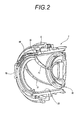
- FIG. 2 is a cross-sectional perspective view of the vicinity of the zoom ring 9 of the lens barrel 2 shown in FIG.
- a rotating cylinder 20 (rotating body) that can rotate around the optical axis of the lens barrel 2 and an inside of the rotating cylinder 20 are provided.
- a zoom lens holding frame 30 for holding the zoom lens is provided.
- the zoom lens holding frame 30 is movable in the optical axis direction of the lens device 2 in conjunction with the rotation of the zoom ring 9.
- the rotating cylinder 20 is formed with a cam groove 21 for converting the linear motion of the zoom lens holding frame 30 into rotational motion.
- a projection of the zoom / lens holding frame 30 is movably mounted in the cam groove 21.
- the rotary cylinder 20 is centered on the optical axis along with this movement. Rotate to.
- the rotary cylinder 20 can be rotated by 300 degrees as an example, but other angles may be rotated.
- a magnetic recording scale member 40 extending along the circumferential direction of the rotating cylinder 20 is fixed to the outer periphery of the rotating cylinder 20.
- An annular member is used as the magnetic recording scale member 40.
- the magnetic recording scale member 40 may not be annular, and may be a linear shape having a length corresponding to the rotatable angle of the rotary cylinder 20.
- a magnetic sensor device 50 is fixed inside the housing 10 at a position facing the magnetic recording scale member 40.
- FIG. 3 is an enlarged view of the magnetic recording scale member 40 and the magnetic sensor device 50 shown in FIG.
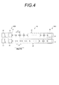
- FIG. 4 is a development view of the magnetic recording scale member 40 shown in FIG.
- the magnetic recording scale member 40 is configured by arranging a first magnetic recording scale 41 and a second magnetic recording scale 42 in parallel so as to be displaced in the optical axis direction.
- the magnetic component of the S pole represented by the letter S and the north pole represented by the letter N is the support 43. And 44 are periodically magnetized.
- the first magnetic recording scale 41 records sine wave information of wavelength ⁇ 1 as magnetic information
- the second magnetic recording scale 42 records sine wave information of wavelength ⁇ 2 longer than wavelength ⁇ 1 as magnetic information. ing.
- the magnetic sensor device 50 includes a first magnetic sensor 51 disposed at a position facing the first magnetic recording scale 41 and a magnetic sensor 52 disposed at a position facing the second magnetic recording scale 42. Yes.
- the first magnetic sensor 51 has two magnetoresistive elements whose electric resistance changes according to the applied magnetic field, and from the magnetic information recorded on the first magnetic recording scale 41, the sine of wavelength ⁇ 1. A wave signal and a cosine wave signal whose phase is shifted by 90 ° with respect to the sine wave signal are detected, and these signals are output.
- the second magnetic sensor 52 also has two magnetoresistive elements whose electric resistance changes according to the applied magnetic field. From the magnetic information recorded on the second magnetic recording scale 42, the second magnetic sensor 52 has a sine of wavelength ⁇ 2. A wave signal and a cosine wave signal whose phase is shifted by 90 ° with respect to the sine wave signal are detected, and these signals are output.
- the position of the magnetic sensor device 50 with respect to the magnetic recording scale member 40 when the rotation angle of the rotary cylinder 20 is 0 ° is indicated by a broken line with an arrow 50A.
- the position of the magnetic sensor device 50 moves relatively leftward from the position indicated by the broken line of the arrow 50A in FIG.
- the magnetic sensor device 50 is relatively positioned as indicated by the chain line of the arrow 50B.
- FIG. 5 is a diagram showing a signal waveform output from the magnetic sensor device 50 when the rotary cylinder 20 shown in FIG. 2 is rotated.
- the B phase is 90 ° out of phase with respect to the A phase. That is, the A phase and the B phase are examples of the first phase signal and the second phase signal, respectively.
- phase C is initially the same phase as the phase A, but every phase (one pulse), the phase advances by 2 ° from the phase A.
- the phase D has a phase of 90 ° relative to the phase C. That is, the C phase and the D phase are examples of the third phase signal and the fourth phase signal, respectively.
- the first magnetic recording scale 41 and the first phase are output so that 150 pulses of the A phase and B phase are output and 149 pulses of the C phase and D phase are output while the rotary cylinder 20 rotates 300 °.
- the second magnetic recording scale 42 is magnetized.
- the diameter ⁇ of the first magnetic recording scale 41 and the second magnetic recording scale 42 is practically about 80 mm.
- the above-mentioned ⁇ 1 that is the magnetization pitch may be about 1.40 mm, and the above ⁇ 2 may be about 1.41 mm.
- FIG. 6 shows a part of the relationship between the count number of the C phase and the phase difference ⁇ between the A phase and the C phase when the zoom lens is moved from the tele side to the wide side.
- FIG. 7 is an enlarged view of a part of FIG.
- the horizontal axis of FIG. 6 is the count number of the C phase
- the vertical axis is the phase difference ⁇ between the A phase and the C phase.
- the phase difference ⁇ between the A phase and the C phase is, for example, arctan (A / B) ⁇ arctan (C / D) (A, B, C, and D are signal levels acquired at arbitrary timings of the respective phases). Is obtained.
- the count number of the C phase corresponds to the rotation number of the zoom lens holding frame 30 (and therefore corresponds to the position of the zoom lens). If the phase difference ⁇ is known, the count number of the C phase, that is, the position of the zoom lens can be known.
- a broken line G10 is an ideal design value with no error, and the phase difference ⁇ gradually decreases as the number of C-phase counts increases.
- solid lines G11, G12 and G13 all indicate values obtained by rotating the magnetic recording scale member 40 magnetized as described above.
- the relationship between the phase difference ⁇ and the C phase count number also depends on the moving speed of the zoom lens, and the relationship between the phase difference ⁇ and the C phase count number changes according to the moving speed.
- the phase difference ⁇ in the ideal design value when the count number is (n-2), (n-1), n, (n + 1), and (n + 2) is Let S (n-2), S (n-1), S (n), S (n + 1), and S (n + 2), respectively.
- the actual phase difference ⁇ when the count number is (n-2), (n-1), n, (n + 1), and (n + 2) is X (n-2), x (n-1), x (n), x (n + 1) and x (n + 2), respectively.
- the actual position when the count number is (n-2), (n-1), n, (n + 1), and (n + 2).
- the phase difference ⁇ is y (n ⁇ 2), y (n ⁇ 1), y (n), y (n + 1), and y (n + 2), respectively.
- the actual phase difference ⁇ when the count number is (n-2), (n-1), n, (n + 1) and (n + 2) is Z (n-2), z (n-1), z (n), z (n + 1), and z (n + 2), respectively.
- the actual phase difference ⁇ and design when the count number is (n-2), (n-1), n, (n + 1), and (n + 2) Differences from the values are d1 (n-2), d1 (n-1), d1 (n), d1 (n + 1), and d1 (n + 2), respectively.
- the actual position when the count number is (n-2), (n-1), n, (n + 1), and (n + 2).
- Differences between the phase difference ⁇ and the design value are d2 (n ⁇ 2), d2 (n ⁇ 1), d2 (n), d2 (n + 1), and d2 (n + 2), respectively.
- the actual phase difference ⁇ and design when the count number is (n-2), (n-1), n, (n + 1), and (n + 2) Differences from the values are d3 (n-2), d3 (n-1), d3 (n), d3 (n + 1), and d3 (n + 2), respectively.
- the correction amount indicating the difference between the above-described phase difference ⁇ and the design value stores an average of the correction amounts of the phase differences corresponding to the five consecutive count numbers.
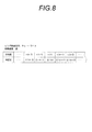
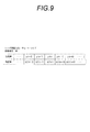
- 8 to 10 are examples of a correction table storing the above-described correction amounts.
- FIGS. 8 to 10 are correction tables used when the zoom lens is moved from the tele side to the wide side, as in FIGS. 6 and 7.
- FIGS. 8, 9 and 10 show correction tables used when the moving speed of the zoom lens is fast, medium and slow, respectively.
- the average of the five differences between the phase difference ⁇ and the design value is stored in the correction table for the phase difference ⁇ corresponding to five consecutive counts.
- the correction amounts for the phase differences x (n ⁇ 2), x (n ⁇ 1), x (n), x (n + 1), and x (n + 2) are respectively ⁇ 1 (n ⁇ 2), ⁇ 1 (n ⁇ 1), ⁇ 1 (n), ⁇ 1 (n + 1), and ⁇ 1 (n + 2).
- the phase differences y (n-2), y (n-1), y (n), y (n) are ⁇ 2 (n ⁇ 2), ⁇ 2 (n ⁇ 1), ⁇ 2 (n), ⁇ 2 (n + 1), and ⁇ 2 (n + 2), respectively. ).
- the phase differences z (n ⁇ 2), z (n ⁇ 1), z (n), z (n) are ⁇ 3 (n ⁇ 2), ⁇ 3 (n ⁇ 1), ⁇ 3 (n), ⁇ 3 (n + 1), and ⁇ 3 (n + 2), respectively.
- a correction table corresponding to the moving speed of the zoom lens is stored in advance, and when the zoom lens is actually moved using the correction table corresponding to the moving speed of the zoom lens.
- the phase difference ⁇ is corrected, and the count number, that is, the position of the zoom lens is detected using the corrected phase difference ⁇ .
- the reason why the correction table corresponding to the moving speed of the zoom lens is used in this way is that the calculated phase difference may differ due to a delay in calculation when the zoom lens is moved at different speeds. .
- the average of the five differences between the phase difference ⁇ and the design value corresponding to five consecutive counts is used as the correction amount, so that even if an error occurs, it is averaged.
- the zoom lens position can be detected with high accuracy.
- the average of the five differences between the phase difference ⁇ and the design value corresponding to the five consecutive counts need not be used as the correction amount.
- FIG. 11 shows a relationship between the count number of the C phase when the zoom lens is moved from the wide side to the tele side and the phase difference ⁇ between the A phase and the C phase. Shows the part.
- the graph G20 when the zoom lens is moved from the wide side to the tele side the middle when the moving speed is high when the zoom lens is moved from the wide side to the tele side
- the graphs G21, G22 and G23 are shown for the case of about and the case of slow.
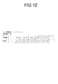
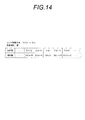
- FIGS. 12 to 14 show correction tables used when the zoom lens is moved from the wide side to the tele side.
- FIG. 12, FIG. 13 and FIG. 14 are correction tables when the moving speed is fast, when the moving speed is medium, and when the moving speed is slow, respectively.
- the correction table stores a correction amount corresponding to the phase difference. These correction amounts are also averaged as described above, but may not be averaged as such.
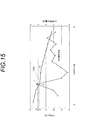
- FIG. 15 shows the relationship between the phase difference and the C-phase count when actually detecting the position of the zoom lens.
- FIG. 15 also shows the amount of change in phase difference corresponding to the number of C-phase counts.
- Graph G shows the phase difference of the design value and the C phase count.
- This graph is the graph G10 shown in FIG. 6 when correcting when the zoom lens moving direction is from the tele side to the wide side, and is corrected when the zoom lens moving direction is from the wide side to the tele side.
- the graph G20 shown in FIG. 11 is obtained.
- the graph G30 shows the relationship between the phase difference obtained according to the movement of the zoom lens at the time of correction and the number of counts.
- the relationship between the phase difference and the number of counts obtained according to the movement of the zoom lens at the time of correction does not match the relationship at the time of design.
- the actual zoom lens position can be obtained by calculating the C phase count (zoom lens position) using the graph G based on the phase difference ⁇ 1. Is calculated to be the position indicated by P2 in spite of the position indicated by P1. Even if the correction described above is performed, it may not be resolved.
- the phase difference ⁇ is calculated for each of the five C-phase counts (if it is plural, it may not be five), and the average value of the calculated phase differences ⁇ is obtained. The position of the zoom lens is detected from this average phase difference.
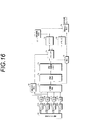
- FIG. 16 is a block diagram showing an electrical configuration of a circuit for detecting the position of the zoom lens holding frame 30 (zoom lens) shown in FIG.
- the circuit shown in FIG. 16 is built in the lens barrel 2.
- the zoom ring 9 is moved so that the zoom lens moves from the tele side to the wide side at a first predetermined speed (as described above, the fast moving speed of the zoom lens).
- a first predetermined speed as described above, the fast moving speed of the zoom lens.
- the first magnetic sensor 51 of the magnetic sensor device 50 outputs the A phase signal and the B phase signal
- the second magnetic sensor 52 outputs the C phase signal and the B phase signal.
- the A-phase signal and B-phase signal output from the first magnetic sensor 51 are input to the first amplifier circuit 60A and the second amplifier circuit 60B, respectively, and are amplified.
- the amplified A-phase signal and B-phase signal are converted into digital A-phase data and B-phase data in analog / digital conversion circuits 61A and 61B.
- the converted A-phase data and B-phase data are input to the phase difference detection circuit 71 and the rotation direction detection circuit 70, respectively.
- the rotation direction of the zoom ring 9 that is, the movement direction of the zoom lens
- the C-phase signal and D-phase signal output from the second magnetic sensor 52 are input to the third amplifier circuit 60C and the fourth amplifier circuit 60D, respectively, and are amplified.
- the amplified C-phase signal and D-phase signal are converted into digital C-phase data and D-phase data in analog / digital conversion circuits 61C and 61D.
- the converted C-phase data and D-phase data are input to the phase difference detection circuit 71.
- phase difference detection circuit 71 the phase difference ⁇ between the A phase and the C phase is periodically detected as described above. As described above, calculation of arctan (A / B) -arctan (C / D) (A, B, C, and D are levels acquired at arbitrary timings of the respective phases) is performed, and the phase difference ⁇ is calculated. Calculated. That is, the phase difference detection circuit 71 functions as an example of a phase difference calculation unit.
- the data indicating the detected phase difference ⁇ is input to the error detection circuit 72.
- the error detection circuit 72 data indicating an error from the design value is obtained.
- the obtained data is temporarily stored in the error temporary storage memory 73.
- the process of rotating the zoom ring 9 at the first predetermined speed to obtain data indicating an error is performed a total of three times and stored in the error temporary storage memory 73. From the average of these data, as shown in FIG. 8, a correction table is generated when the zoom lens moves from the tele side to the wide side at a high speed. The generated correction table is input to the first memory 76 via the switch 74 and stored.
- the zoom ring 9 is rotated at the second predetermined speed (the speed at which the above-described zoom lens moves at a middle position), and similarly, the correction table shown in FIG. 9 is obtained. Further, the zoom ring 9 is rotated at the third predetermined speed (the speed at which the above-described zoom lens moves at a low speed), and similarly, the correction table shown in FIG. 10 is obtained.
- the obtained correction table is also stored in the first memory 76.
- the correction table shown in FIG. 12 the correction table shown in FIG. 13, and the correction table shown in FIG. can get.
- the obtained correction table is stored in the second memory 77. That is, the first memory 75 and the second memory 76 function as an example of a correction table memory.
- A-phase data, B-phase data, C-phase data and D-phase data are obtained as described above.
- the direction of rotation is detected. From the detected rotation direction, it can be seen whether the zoom lens is moving from the tele side to the wide side or from the wide side to the tele side. Further, the rotation speed detection circuit 75 detects the rotation speed of the zoom ring 9, and the movement speed of the zoom lens is known.
- a correction table corresponding to the moving speed is read from the first memory 76 and the second memory 77. For example, if the moving speed of the zoom lens is high, the correction table shown in FIG.
- a correction table corresponding to the rotation direction (zoom / lens movement direction) detected by the rotation direction detection circuit 70 passes through the switch circuit 74.
- the correction table shown in FIG. 8 passes through the switch circuit 74 and is input to the correction circuit 78, and the movement direction of the zoom lens is from the wide side to the tele side. 12, the correction table shown in FIG. 12 passes through the switch circuit 74 and is input to the correction circuit 78.
- the data indicating the phase difference ⁇ output from the phase difference detection circuit 71 is also input to the correction circuit 78, and the input data indicating the phase difference ⁇ is corrected by the correction table. That is, the correction circuit 78 functions as an example of a phase difference correction unit. Data indicating the corrected phase difference ⁇ is input to the current position detection circuit 79, and the current position of the zoom lens is detected. A method of detecting the current position of the zoom lens will be described.
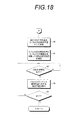
- FIG. 17 and FIG. 18 are flowcharts showing the zoom lens position detection processing procedure
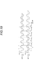
- FIG. 19 is a waveform diagram of signals output from the magnetic sensor device 50 when the zoom ring 9 is rotated in one direction. .
- the first processing in FIG. 17 is performed.
- the A-phase data, B-phase data, C-phase data, and D-phase data corresponding to the current zoom lens position are converted into analog / digital conversion circuits 61A, 61B, 61C. And 61D. It is assumed that the power is turned on at the timing shown at time T0 in FIG.
- the phase difference detection circuit 71 checks whether there are any changes in the A phase data, the B phase data, the C phase data, and the D phase data (step 81). After the power is turned on, the zoom ring 9 is rotated in one direction by the user, and if there is a change in the A phase data, B phase data, C phase data, and D phase data (YES in step 81), the phase difference detection circuit 71 At step 82, it is determined whether A-phase data, B-phase data, C-phase data, and D-phase data for one cycle (one pulse) have been detected (step 82).
- a phase data, B phase data, C phase data, and D phase data for one cycle (one pulse) are detected, A phase data, B phase data, and C phase data for one cycle (one pulse)
- the D phase data is normalized and stored in a memory (not shown) included in the phase difference detection circuit 71 (step 83).
- step 84 If the A-phase data, B-phase data, C-phase data, and D-phase data for 5 pulses are not stored in the memory within the phase difference detection circuit 71 (NO in step 84), the processing from step 81 is repeated.
- the rotation direction detection circuit 70 makes the zoom ring 9
- the rotation speed of the zoom ring 9 is detected by the rotation speed detection circuit 75 (step 85). From the detected rotation direction and rotation speed, a correction table used for correction is determined as described above (step 86).
- the A-phase data obtained at an arbitrary timing for example, the timing at which the A-phase amplitude becomes 0
- Arctan (A / B) -arctan (C / D) is calculated using the B-phase data, C-phase data, and D-phase data, and the phase difference ⁇ is calculated for each of the five pulses (step 87).
- the phase difference detection circuit 71 performs time T1 for each of the first pulse, the second pulse, the third pulse, the fourth pulse, and the fifth pulse output after the power is turned on. , T2, T3, T4, and T5, the phase differences ⁇ (1), ⁇ (2), ⁇ (3), ⁇ (4) and ⁇ (5) are respectively calculated.
- the average value of the phase differences ⁇ (1) to ⁇ (5) is calculated in the phase difference detection circuit 71 (step 88), and the correction amount of the calculated phase difference of the average value is determined as the determined correction value.
- the value is read from the table and corrected by the read correction amount (step 89), and the corrected average value is set as the phase difference at the third pulse, the phase difference at the third pulse and the first memory.
- the absolute position of the zoom lens corresponding to the phase difference of the third pulse (2 pulses before the current position) is obtained from the data that correlates the phase difference of the design value and the zoom lens position indicated in 76. Is determined (step 91).
- the current position detection circuit 79 adds or subtracts a movement amount corresponding to two pulses to the determined absolute position according to the rotation direction (zoom lens movement direction) output from the rotation direction detection circuit 70. Then, the absolute position of the zoom lens is determined (step 91).
- the current position detection circuit 79 adds a movement amount corresponding to two pulses to the determined absolute position. To confirm the absolute position. On the other hand, if the movement direction of the zoom lens is a direction in which the phase difference ⁇ changes from a large value to a small value, the current position detection circuit 79 subtracts a movement amount corresponding to two pulses from the determined absolute position. Confirm the absolute position. That is, the current position detection circuit 79 functions as an example of absolute position calculation means.
- the current position detection circuit 79 may output the determined absolute position to a display unit connected to the imaging apparatus main body 1 to notify the user.
- the A-phase data and the B-phase data signal are compared to move the zoom lens. Is counted, and the number of pulses of the A-phase data or B-phase data (for example, the number of pulses with accuracy multiplied by 64) is counted, and the relative position of the zoom lens with the determined absolute position as the reference position is detected. (Step S90).
- the current position of the zoom lens is determined based on a value obtained by correcting the average value of the phase differences obtained for each of the five pulses output from the magnetic sensor device 50.
- the influence of the uneven magnetization of the magnetic recording scale member 40 or the incorporation error of the lens barrel 2 can be reduced, and the detection accuracy of the current position can be improved.
- the average value of the phase difference for 5 pulses is used, but when the average value of the phase difference for 7 pulses is used, the average of the phase differences ⁇ obtained for each of the 7 pulses.
- the absolute position of the zoom lens at the 4th pulse is determined by this phase difference, and then the position shifted by 3 pulses from this absolute position is absolute What is necessary is just to confirm as a position.
- the value obtained by correcting the average value of the phase difference ⁇ obtained for each of the four pulses corresponds to the second pulse or the third pulse.
- the position shifted by two or one pulse from this absolute position can be determined as the absolute position. That's fine.
- the phase difference detection circuit 71 determines the absolute position corresponding to the value obtained by correcting the average value of the phase difference ⁇ calculated for each pulse.
- the final absolute position is determined by shifting the number of pulses divided by the quotient when dividing by 2. If the number of pulses is an even number, the absolute position corresponding to the average value of the phase difference ⁇ calculated for each pulse of the number of pulses is expressed as “quotient when the number of pulses is divided by 2” or “ (Quotient when the number of pulses is divided by 2) -1 ”The final absolute position is determined by shifting by the pulse.
- the number of pulses described above is preferably 3 or more considering the accuracy of the absolute position.
- the number of pulses is output from the magnetic sensor device 50 according to the angle at which the rotating cylinder 20 is rotated by one rotation operation (about 10 ° to 20 ° if the diameter ⁇ of the rotating cylinder 20 is about 80 mm). It is preferable to keep the same as the number of pulses (about 5 to 10).
- the user can know the absolute position of the zoom lens by simply turning the zoom ring 9 once in a certain direction after turning on the power of the lens barrel 20. , Work up to grasping the absolute position is simplified.
- the data obtained at the timing when the amplitude of the A-phase signal becomes 0 is used to calculate the phase difference.
- the data obtained at an arbitrary timing can be used.
- the phase difference ⁇ obtained from the data of the A phase, B phase, C phase, and D phase obtained when the amplitude of any of the A phase, B phase, C phase, or D phase becomes 0 is the A phase, B phase Compared with the phase difference ⁇ obtained from the data of the A phase, the B phase, the C phase, and the D phase obtained when the amplitude of each of the C phase and the D phase does not become 0, the value closer to the designed phase difference ( (Value with less error). Therefore, for each pulse, the phase difference ⁇ is calculated from the data of the A phase, B phase, C phase, or D phase obtained when the amplitude of any of the A phase, B phase, C phase, or D phase becomes 0. By calculating, the accuracy of the absolute position of the zoom lens finally obtained can be improved.
- the zoom lens has been described, but the present invention can also be applied to a focus lens other than the zoom lens.
Landscapes
- Physics & Mathematics (AREA)
- General Physics & Mathematics (AREA)
- Optics & Photonics (AREA)
- Lens Barrels (AREA)
- Measurement Of Length, Angles, Or The Like Using Electric Or Magnetic Means (AREA)
- Structure And Mechanism Of Cameras (AREA)
Description
8 フォーカス・リング
9 ズーム・リング
11 アイリス・リング
40 磁気記録スケール部材
50 磁気センサ装置
70 回転方向検出回路
71 位相差検出回路
75 回転速度検出回路
76 第1のメモリ
77 第2のメモリ
78 補正回路
79 現在位置検出回路
Claims (5)
- 光軸方向に移動可能に撮像レンズを保持する鏡筒本体,
上記撮像レンズの移動に応じて回転する回転体であって,周方向に沿って,それぞれが異なる波長の磁気成分が周期的に着磁されている第1の磁気スケールおよび第2の磁気スケールが平行に形成されている回転体,
上記回転体が回転することによって,上記第1の磁気スケールから第1の位相信号および第1の位相信号に対し位相のずれた第2の位相信号を検出する第1の磁気センサ,
上記回転体が回転することによって,上記第2の磁気スケールから第3の位相信号および第3の位相信号に対し位相のずれた第4の位相信号を検出する第2の磁気センサ,
上記第1の磁気センサにおいて検出された第1の位相信号および第2の位相信号ならびに上記第2の磁気センサにおいて検出された第3の位相信号および第4の位相信号を用いて第1の位相信号と第3の位相信号との位相差を算出する位相差算出手段,
異なる速度で上記撮像レンズを移動した場合に得られる,上記位相差算出手段において算出された位相差と上記位相差の設計値との差分を補正する複数の補正テーブルを記憶する補正テーブル・メモリ,
上記複数の補正テーブルのうち,上記撮像レンズの移動速度に対応した補正テーブルを用いて上記位相差算出手段において算出された位相差を補正する位相差補正手段,ならびに
上記位相差補正手段によって補正された位相差と,あらかじめ定められている位相差と撮像レンズの絶対位置との関係と,から上記撮像レンズの絶対位置を算出する絶対位置算出手段,
を備えた撮像レンズ鏡筒。
- 上記補正テーブル・メモリには,
上記異なる速度のそれぞれについて、異なる方向に上記撮像レンズを移動した場合に得られる,上記位相差算出手段において算出された位相差と上記位相差の設計値との差分を示す2つの補正テーブルが記憶されており,
上記位相差補正手段は,
上記2つの補正テーブルのうち,上記撮像レンズの移動方向に対応した補正テーブルを用いて上記位相差算出手段において算出された位相差を補正する,
請求項1に記載の撮像レンズ鏡筒。
- 上記位相差算出手段は,
上記第1の磁気センサにおいて検出された第1の位相信号および第2の位相信号ならびに上記第2の磁気センサにおいて検出された第3の位相信号および第4の位相信号を用いて算出された位相差のn個分の平均を算出する,
請求項1または2に記載の撮像レンズ鏡筒。
- 上記補正データ・メモリには,
撮像レンズの移動位置ごとに,移動位置に対応する上記位相差を含むn個の位相差についての上記位相差の設計値との差分の平均が補正テーブルとして記憶されている,
請求項3に記載の撮像レンズ鏡筒。
- 光軸方向に移動可能に撮像レンズを保持する鏡筒本体および上記撮像レンズの移動に応じて回転する回転体であって,周方向に沿って,それぞれが異なる波長の磁気成分が周期的に着磁されている第1の磁気スケールおよび第2の磁気スケールが平行に形成されている回転体を備えた撮像レンズ鏡筒の動作制御方法において,
第1の磁気センサが,上記回転体が回転することによって,上記第1の磁気スケールから第1の位相信号および第1の位相信号に対し位相のずれた第2の位相信号を検出し,
第2の磁気センサが,上記回転体が回転することによって,上記第2の磁気スケールから第3の位相信号および第3の位相信号に対し位相のずれた第4の位相信号を検出し,
位相差算出手段が,上記第1の磁気センサにおいて検出された第1の位相信号および第2の位相信号ならびに上記第2の磁気センサにおいて検出された第3の位相信号および第4の位相信号を用いて第1の位相信号と第3の位相信号との位相差を算出し,
位相差補正手段が,異なる速度で上記撮像レンズを移動した場合に得られる,上記位相差算出手段において算出された位相差と上記位相差の設計値との差分を補正する複数の補正テーブルのうち,上記撮像レンズの移動速度に対応した補正テーブルを用いて上記位相差算出手段において算出された位相差を補正し,
絶対位置算出手段が,上記位相差補正手段によって補正された位相差と,あらかじめ定められている位相差と撮像レンズの絶対位置との関係と,から撮像レンズの絶対位置を算出する,
撮像レンズ鏡筒の動作制御方法。
Priority Applications (3)
| Application Number | Priority Date | Filing Date | Title |
|---|---|---|---|
| JP2014532881A JP5736519B2 (ja) | 2012-08-30 | 2013-07-18 | 撮像レンズ鏡筒およびその動作制御方法 |
| CN201380042718.0A CN104704327B (zh) | 2012-08-30 | 2013-07-18 | 摄像透镜镜筒及其动作控制方法 |
| US14/624,594 US9372324B2 (en) | 2012-08-30 | 2015-02-18 | Imaging lens barrel and method for controlling operation of the same |
Applications Claiming Priority (2)
| Application Number | Priority Date | Filing Date | Title |
|---|---|---|---|
| JP2012189446 | 2012-08-30 | ||
| JP2012-189446 | 2012-08-30 |
Related Child Applications (1)
| Application Number | Title | Priority Date | Filing Date |
|---|---|---|---|
| US14/624,594 Continuation US9372324B2 (en) | 2012-08-30 | 2015-02-18 | Imaging lens barrel and method for controlling operation of the same |
Publications (1)
| Publication Number | Publication Date |
|---|---|
| WO2014034316A1 true WO2014034316A1 (ja) | 2014-03-06 |
Family
ID=50183136
Family Applications (1)
| Application Number | Title | Priority Date | Filing Date |
|---|---|---|---|
| PCT/JP2013/069539 Ceased WO2014034316A1 (ja) | 2012-08-30 | 2013-07-18 | 撮像レンズ鏡筒およびその動作制御方法 |
Country Status (4)
| Country | Link |
|---|---|
| US (1) | US9372324B2 (ja) |
| JP (1) | JP5736519B2 (ja) |
| CN (1) | CN104704327B (ja) |
| WO (1) | WO2014034316A1 (ja) |
Cited By (1)
| Publication number | Priority date | Publication date | Assignee | Title |
|---|---|---|---|---|
| US20140340560A1 (en) * | 2012-01-30 | 2014-11-20 | Fujifilm Corporation | Lens device and position detection method of movable optical element |
Families Citing this family (4)
| Publication number | Priority date | Publication date | Assignee | Title |
|---|---|---|---|---|
| JP6289192B2 (ja) * | 2014-03-20 | 2018-03-07 | キヤノン株式会社 | 位置検出装置及びそれを有するレンズ装置及び光学操作装置 |
| JP6236578B2 (ja) * | 2015-09-30 | 2017-11-22 | 富士フイルム株式会社 | 可動レンズの位置検出装置、レンズ装置、撮像装置、可動レンズの位置検出方法、及び、可動レンズの位置検出プログラム |
| JP7070556B2 (ja) * | 2017-04-13 | 2022-05-18 | ソニーグループ株式会社 | 位置検出装置及び位置検出方法 |
| US11346688B2 (en) * | 2020-07-06 | 2022-05-31 | Allegro Microsystems, Llc | Magnetic field sensors for detecting absolute position of multi-track targets |
Citations (3)
| Publication number | Priority date | Publication date | Assignee | Title |
|---|---|---|---|---|
| JPH0658766A (ja) * | 1992-08-05 | 1994-03-04 | Hitachi Ltd | 絶対位置検出装置およびモ−タ制御装置 |
| JP2006029937A (ja) * | 2004-07-15 | 2006-02-02 | Matsushita Electric Ind Co Ltd | 回転角度検出装置の回転角補正方法 |
| JP2008533476A (ja) * | 2005-03-14 | 2008-08-21 | ローベルト ボツシユ ゲゼルシヤフト ミツト ベシユレンクテル ハフツング | 運動または回転角を検出する際にチルト角を把握および補償するための方法および回路装置 |
Family Cites Families (5)
| Publication number | Priority date | Publication date | Assignee | Title |
|---|---|---|---|---|
| JP2010204206A (ja) * | 2009-02-27 | 2010-09-16 | Sony Corp | 光量調整装置、レンズ鏡筒、撮像装置、及び撮像装置の制御方法 |
| JP5290080B2 (ja) | 2009-07-24 | 2013-09-18 | オリンパス株式会社 | 内視鏡装置 |
| JP5646946B2 (ja) | 2010-10-14 | 2014-12-24 | 旭化成エレクトロニクス株式会社 | 位置検出装置及びそれを備えた電子機器 |
| JP5736518B2 (ja) * | 2012-08-30 | 2015-06-17 | 富士フイルム株式会社 | 撮像レンズ鏡筒およびその動作制御方法 |
| WO2014034317A1 (ja) * | 2012-08-30 | 2014-03-06 | 富士フイルム株式会社 | 撮像レンズ鏡筒およびその動作制御方法 |
-
2013
- 2013-07-18 CN CN201380042718.0A patent/CN104704327B/zh active Active
- 2013-07-18 WO PCT/JP2013/069539 patent/WO2014034316A1/ja not_active Ceased
- 2013-07-18 JP JP2014532881A patent/JP5736519B2/ja not_active Expired - Fee Related
-
2015
- 2015-02-18 US US14/624,594 patent/US9372324B2/en active Active
Patent Citations (3)
| Publication number | Priority date | Publication date | Assignee | Title |
|---|---|---|---|---|
| JPH0658766A (ja) * | 1992-08-05 | 1994-03-04 | Hitachi Ltd | 絶対位置検出装置およびモ−タ制御装置 |
| JP2006029937A (ja) * | 2004-07-15 | 2006-02-02 | Matsushita Electric Ind Co Ltd | 回転角度検出装置の回転角補正方法 |
| JP2008533476A (ja) * | 2005-03-14 | 2008-08-21 | ローベルト ボツシユ ゲゼルシヤフト ミツト ベシユレンクテル ハフツング | 運動または回転角を検出する際にチルト角を把握および補償するための方法および回路装置 |
Cited By (2)
| Publication number | Priority date | Publication date | Assignee | Title |
|---|---|---|---|---|
| US20140340560A1 (en) * | 2012-01-30 | 2014-11-20 | Fujifilm Corporation | Lens device and position detection method of movable optical element |
| US8942553B2 (en) * | 2012-01-30 | 2015-01-27 | Fujifilm Corporation | Lens device and position detection method of movable optical element |
Also Published As
| Publication number | Publication date |
|---|---|
| US20150160427A1 (en) | 2015-06-11 |
| CN104704327B (zh) | 2016-03-30 |
| US9372324B2 (en) | 2016-06-21 |
| CN104704327A (zh) | 2015-06-10 |
| JP5736519B2 (ja) | 2015-06-17 |
| JPWO2014034316A1 (ja) | 2016-08-08 |
Similar Documents
| Publication | Publication Date | Title |
|---|---|---|
| JP5736518B2 (ja) | 撮像レンズ鏡筒およびその動作制御方法 | |
| JP5736519B2 (ja) | 撮像レンズ鏡筒およびその動作制御方法 | |
| US8942553B2 (en) | Lens device and position detection method of movable optical element | |
| JP6053985B2 (ja) | レンズ装置、撮像装置、可動レンズの位置検出方法 | |
| US10620400B2 (en) | Position detection device for movable lens, lens device, imaging device, position detection method for movable lens, and non-transitory computer readable medium storing a position detection program for movable lens | |
| JP5736520B2 (ja) | 撮像レンズ鏡筒およびその動作制御方法 | |
| JP2013027215A (ja) | モータ制御装置および光学機器 | |
| JP5802857B2 (ja) | レンズ装置及び可動光学素子の位置検出方法 | |
| JP6031415B2 (ja) | レンズ装置及び可動光学素子の位置検出方法 | |
| JP5038176B2 (ja) | 光学機器 | |
| JP2013003352A (ja) | 光学装置及び撮像装置 |
Legal Events
| Date | Code | Title | Description |
|---|---|---|---|
| WWE | Wipo information: entry into national phase |
Ref document number: 201380042718.0 Country of ref document: CN |
|
| 121 | Ep: the epo has been informed by wipo that ep was designated in this application |
Ref document number: 13833864 Country of ref document: EP Kind code of ref document: A1 |
|
| ENP | Entry into the national phase |
Ref document number: 2014532881 Country of ref document: JP Kind code of ref document: A |
|
| NENP | Non-entry into the national phase |
Ref country code: DE |
|
| 122 | Ep: pct application non-entry in european phase |
Ref document number: 13833864 Country of ref document: EP Kind code of ref document: A1 |