WO2014034145A1 - 補助用具 - Google Patents
補助用具 Download PDFInfo
- Publication number
- WO2014034145A1 WO2014034145A1 PCT/JP2013/005157 JP2013005157W WO2014034145A1 WO 2014034145 A1 WO2014034145 A1 WO 2014034145A1 JP 2013005157 W JP2013005157 W JP 2013005157W WO 2014034145 A1 WO2014034145 A1 WO 2014034145A1
- Authority
- WO
- WIPO (PCT)
- Prior art keywords
- actuator
- auxiliary tool
- attached
- unit
- power supply
- Prior art date
- Legal status (The legal status is an assumption and is not a legal conclusion. Google has not performed a legal analysis and makes no representation as to the accuracy of the status listed.)
- Ceased
Links
Images







Classifications
-
- A—HUMAN NECESSITIES
- A61—MEDICAL OR VETERINARY SCIENCE; HYGIENE
- A61H—PHYSICAL THERAPY APPARATUS, e.g. DEVICES FOR LOCATING OR STIMULATING REFLEX POINTS IN THE BODY; ARTIFICIAL RESPIRATION; MASSAGE; BATHING DEVICES FOR SPECIAL THERAPEUTIC OR HYGIENIC PURPOSES OR SPECIFIC PARTS OF THE BODY
- A61H1/00—Apparatus for passive exercising; Vibrating apparatus; Chiropractic devices, e.g. body impacting devices, external devices for briefly extending or aligning unbroken bones
- A61H1/02—Stretching or bending or torsioning apparatus for exercising
- A61H1/0237—Stretching or bending or torsioning apparatus for exercising for the lower limbs
- A61H1/0244—Hip
-
- A—HUMAN NECESSITIES
- A61—MEDICAL OR VETERINARY SCIENCE; HYGIENE
- A61H—PHYSICAL THERAPY APPARATUS, e.g. DEVICES FOR LOCATING OR STIMULATING REFLEX POINTS IN THE BODY; ARTIFICIAL RESPIRATION; MASSAGE; BATHING DEVICES FOR SPECIAL THERAPEUTIC OR HYGIENIC PURPOSES OR SPECIFIC PARTS OF THE BODY
- A61H1/00—Apparatus for passive exercising; Vibrating apparatus; Chiropractic devices, e.g. body impacting devices, external devices for briefly extending or aligning unbroken bones
- A61H1/02—Stretching or bending or torsioning apparatus for exercising
- A61H1/0237—Stretching or bending or torsioning apparatus for exercising for the lower limbs
- A61H1/024—Knee
-
- A—HUMAN NECESSITIES
- A61—MEDICAL OR VETERINARY SCIENCE; HYGIENE
- A61H—PHYSICAL THERAPY APPARATUS, e.g. DEVICES FOR LOCATING OR STIMULATING REFLEX POINTS IN THE BODY; ARTIFICIAL RESPIRATION; MASSAGE; BATHING DEVICES FOR SPECIAL THERAPEUTIC OR HYGIENIC PURPOSES OR SPECIFIC PARTS OF THE BODY
- A61H3/00—Appliances for aiding patients or disabled persons to walk about
-
- B—PERFORMING OPERATIONS; TRANSPORTING
- B25—HAND TOOLS; PORTABLE POWER-DRIVEN TOOLS; MANIPULATORS
- B25J—MANIPULATORS; CHAMBERS PROVIDED WITH MANIPULATION DEVICES
- B25J9/00—Program-controlled manipulators
- B25J9/0006—Exoskeletons, i.e. resembling a human figure
-
- B—PERFORMING OPERATIONS; TRANSPORTING
- B25—HAND TOOLS; PORTABLE POWER-DRIVEN TOOLS; MANIPULATORS
- B25J—MANIPULATORS; CHAMBERS PROVIDED WITH MANIPULATION DEVICES
- B25J9/00—Program-controlled manipulators
- B25J9/10—Program-controlled manipulators characterised by positioning means for manipulator elements
- B25J9/1095—Program-controlled manipulators characterised by positioning means for manipulator elements chemically actuated
-
- A—HUMAN NECESSITIES
- A61—MEDICAL OR VETERINARY SCIENCE; HYGIENE
- A61H—PHYSICAL THERAPY APPARATUS, e.g. DEVICES FOR LOCATING OR STIMULATING REFLEX POINTS IN THE BODY; ARTIFICIAL RESPIRATION; MASSAGE; BATHING DEVICES FOR SPECIAL THERAPEUTIC OR HYGIENIC PURPOSES OR SPECIFIC PARTS OF THE BODY
- A61H2201/00—Characteristics of apparatus not provided for in the preceding codes
- A61H2201/12—Driving means
- A61H2201/1207—Driving means with electric or magnetic drive
- A61H2201/123—Linear drive
-
- A—HUMAN NECESSITIES
- A61—MEDICAL OR VETERINARY SCIENCE; HYGIENE
- A61H—PHYSICAL THERAPY APPARATUS, e.g. DEVICES FOR LOCATING OR STIMULATING REFLEX POINTS IN THE BODY; ARTIFICIAL RESPIRATION; MASSAGE; BATHING DEVICES FOR SPECIAL THERAPEUTIC OR HYGIENIC PURPOSES OR SPECIFIC PARTS OF THE BODY
- A61H2201/00—Characteristics of apparatus not provided for in the preceding codes
- A61H2201/16—Physical interface with patient
- A61H2201/1602—Physical interface with patient kind of interface, e.g. head rest, knee support or lumbar support
- A61H2201/1628—Pelvis
- A61H2201/163—Pelvis holding means therefor
-
- A—HUMAN NECESSITIES
- A61—MEDICAL OR VETERINARY SCIENCE; HYGIENE
- A61H—PHYSICAL THERAPY APPARATUS, e.g. DEVICES FOR LOCATING OR STIMULATING REFLEX POINTS IN THE BODY; ARTIFICIAL RESPIRATION; MASSAGE; BATHING DEVICES FOR SPECIAL THERAPEUTIC OR HYGIENIC PURPOSES OR SPECIFIC PARTS OF THE BODY
- A61H2201/00—Characteristics of apparatus not provided for in the preceding codes
- A61H2201/16—Physical interface with patient
- A61H2201/1602—Physical interface with patient kind of interface, e.g. head rest, knee support or lumbar support
- A61H2201/164—Feet or leg, e.g. pedal
- A61H2201/1642—Holding means therefor
-
- A—HUMAN NECESSITIES
- A61—MEDICAL OR VETERINARY SCIENCE; HYGIENE
- A61H—PHYSICAL THERAPY APPARATUS, e.g. DEVICES FOR LOCATING OR STIMULATING REFLEX POINTS IN THE BODY; ARTIFICIAL RESPIRATION; MASSAGE; BATHING DEVICES FOR SPECIAL THERAPEUTIC OR HYGIENIC PURPOSES OR SPECIFIC PARTS OF THE BODY
- A61H2201/00—Characteristics of apparatus not provided for in the preceding codes
- A61H2201/16—Physical interface with patient
- A61H2201/1602—Physical interface with patient kind of interface, e.g. head rest, knee support or lumbar support
- A61H2201/165—Wearable interfaces
Definitions
- the present invention relates to an auxiliary tool.
- Patent Document 1 Japanese Patent Application Laid-Open No. 2003-153828
- auxiliary tools can be worn like clothes, it is preferable that they can be washed when dirty.
- an auxiliary tool using an actuator that operates by applying a voltage there is a problem that it cannot be easily washed.
- an auxiliary tool for assisting the movement of the body an attachment portion attached to the body, an actuator including a polymer material that expands or contracts when a voltage is applied, and the actuator.
- a mounting portion attached to the mounting portion, and the mounting portion is detachably attached together with the actuator.
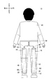
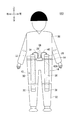
- FIG. 3 is a front view of a user wearing the auxiliary tool 10.
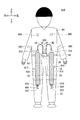
- FIG. 3 is a rear view of a user wearing the auxiliary tool 10.
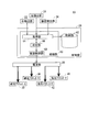
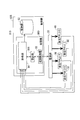
- 3 is a block diagram illustrating a control system of the auxiliary tool 10.
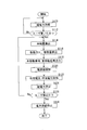
- FIG. 5 is a flowchart of auxiliary tool control processing executed by the auxiliary tool 10. It is a right view explaining auxiliary tool 110 which changed the attachment position of an artificial muscle part. It is a front view explaining the auxiliary tool 210 which changed the attachment position of the artificial muscle part. It is a right view explaining the auxiliary tool 210 which changed the attachment position of the artificial muscle part. It is a front view explaining the auxiliary tool 310 which changed the attachment position of the artificial muscle part. It is a front view explaining the auxiliary tool 410 which changed attachment of the artificial muscle part.
- FIG. 5 is a flowchart of an artificial muscle control process executed by an auxiliary tool 810. It is a front view of a user wearing an auxiliary tool 910. It is a rear view of the user wearing the auxiliary tool 910.
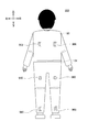
- FIG. 1 is a front view of a user wearing the auxiliary tool 10.
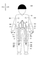
- FIG. 2 is a rear view of the user wearing the auxiliary tool 10.
- the vertical and horizontal directions indicated by arrows in FIG. 1 are the vertical and horizontal directions of the auxiliary tool 10.
- the front and rear directions viewed from the user are the front and rear directions of the auxiliary tool 10.
- a belt 84 is wound around the waist of the body of the trousers 82.
- the belt 84 has a buckle 86 disposed on the front surface of the body.
- the upper part of the shirt 80 is formed so as not to deviate from the shoulder.
- the hem of the pants 82 is narrowed so as not to be displaced from the ankle.
- the inner surface of the shirt 80 and the trousers 82 may be configured like a diving suit that is in close contact with the user's body.
- the shirt 80, the trousers 82, and the belt 84 are an example of a mounting portion that is attached to the body.
- the belt 84 is an example of the portion of the mounting portion that is fixed to the body.
- the auxiliary device 10 includes an anterior right artificial muscle portion 12, an anterior left artificial muscle portion 14, a posterior right artificial muscle portion 16, an posterior left artificial muscle portion 18, and a power supply portion 20. And a right detection unit 22 and a left detection unit 24, which are examples of the detection unit, a mounting detection unit 26, and a control unit 28.
- the front right artificial muscle portion 12 includes a front right actuator 30, a pair of front right attachment portions 32, and a power wiring 34.
- the front right actuator 30 is formed to extend in the vertical direction.
- One end of the front right actuator 30 in the up-down direction, that is, the longitudinal direction, is disposed on the front surface of the shirt 80 above the right foot and above the belt 84 and the waist of the user.
- the other end in the longitudinal direction of the front right actuator 30 is disposed on the front surface of the trousers 82 below the knee of the right foot.
- the front right actuator 30 is provided so as to straddle the waist and knee joints of the user's torso.
- the front right actuator 30 includes a polymer material that expands and contracts when a voltage is applied. When a voltage is applied, the front right actuator 30 expands and contracts in the vertical direction, that is, in the longitudinal direction. As a result, the front right actuator 30 contracts to assist the user's right leg ascending when walking.
- the polymer material is a crosslinked polyrotaxane.
- the front right actuator 30 is produced by winding a sheet member in which both surfaces of a planar polyrotaxane crosslinked body are sandwiched between stretchable electrodes.
- the longitudinal direction of the front right actuator 30 is parallel to the axial direction of the wound sheet member. Since the front right actuator 30 has flexibility, it can reduce a user's uncomfortable feeling when walking in a worn state.
- polymer material is a polypyrrole film.
- the polypyrrole film immersed in the electrolytic solution expands or contracts when a voltage is applied. For example, when a positive voltage is applied, the polypyrrole film expands. When a negative voltage is applied, the polypyrrole film contracts. Note that when the front right actuator 30 includes a polypyrrole film, an electrolyte is required, and thus the front right actuator 30 needs to be sealed.
- polyvinyl chloride (PVC) gel Provided in contact with the outer surfaces of the mesh body made of a conductive material, the first PVC gel and the second PVC gel disposed opposite to each other at a position sandwiching the mesh body, and the first PVC gel and the second PVC gel.
- the first electrode and the second electrode are formed.
- the mesh body is connected to the anode, the first and second electrodes are connected to the cathode, When a voltage is applied between the body and the first and second electrodes, part of the first and second PVC gels enter the mesh holes of the mesh body and are displaced in the thickness direction.
- PVC is an example of a material constituting the gel
- dielectric polymer materials such as polymethyl methacrylate, polyurethane, polystyrene, polyvinyl acetate, and nylon 6 may be used.
- an actuator made of PVC gel may be laminated to improve the output of the actuator.
- the mesh body of each actuator is connected to the anode, and the first and second electrodes are each connected to the cathode.
- the pair of front right attachment portions 32 attach both ends of the front right actuator 30 in the expansion / contraction direction to clothes.
- One front right attachment portion 32 is provided at the upper end portion of the front right actuator 30 and attached to the front surface of the shirt 80.
- the upper end portion of the front right actuator 30 may be attached to the belt 84 that is difficult to move due to the stretching force via the one front right attachment portion 32.
- the other front right attachment portion 32 is provided at the lower end portion of the front right actuator 30 and attached to the front surface of the pants 82.
- the front right attachment portion 32 is detachably attached to the shirt 80 or the trousers 82 together with the front right actuator 30 by a button, a chuck, a magic tape (registered trademark), or the like.
- Part of the pair of front right mounting portions 32 is preferably made of an elastic member such as rubber.
- One end of the power wiring 34 is electrically connected to the front right actuator 30 via the upper front right mounting portion 32.
- the other end of the power wiring 34 is connected to the power supply unit 20.
- the power wiring 34 electrically connects the front right actuator 30 and the power supply unit 20.
- front left artificial muscle part 14 the rear right artificial muscle part 16, and the rear left artificial muscle part 18 have the same configuration as the front right artificial muscle part 12, their description is omitted except for the differences.
- the front left artificial muscle portion 14 includes a front left actuator 36, a pair of front left attachment portions 38, and a power wiring 40.
- the front left actuator 36 is attached to the front surface of the trousers 82 from the front surface of the shirt 80 above the waist to the lower part of the knee of the left foot by a pair of front left mounting portions 38. Note that one end of the front left actuator 36 may be attached to the belt 84 that is difficult to move due to the expansion and contraction force.
- the front left actuator 36 contracts to assist the user's left leg ascending when walking.
- the power wiring 40 electrically connects the front left actuator 36 and the power supply unit 20.
- the rear right artificial muscle portion 16 includes a rear right actuator 42, a pair of rear right attachment portions 44, and a power wiring 46.
- the rear right actuator 42 is attached to the rear surface of the trouser 82 by a pair of rear right attachment portions 44 from the rear surface of the trouser 82 at the base of the right foot to the vicinity of the ankle below the knee of the right foot.
- the rear right actuator 42 may be attached to the belt 84, the shirt 80, or the like. Further, the rear right actuator 42 may have a length up to below the knee.
- the rear right actuator 42 is disposed inside the pocket 88 of the trousers 82.
- the pocket 88 is preferably made of a material that can expand and contract with the expansion and contraction of the rear right actuator 42.
- the power wiring 46 electrically connects the rear right actuator 42 and the power supply unit 20 via a wiring disposed on the back of the belt 84.
- the rear left artificial muscle portion 18 includes a rear left actuator 48, a pair of rear left attachment portions 50, and a power wiring 52.
- the rear left actuator 48 is attached to the rear surface of the trouser 82 by a pair of rear left mounting portions 50 from the rear surface of the trouser 82 at the base of the left foot to the vicinity of the ankle below the knee of the left foot.
- the rear left actuator 48 may be attached to the belt 84 and the shirt 80. Further, the rear left actuator 48 may have a length up to below the knee.
- the pocket 88 is preferably made of a material that can expand and contract with the expansion and contraction of the rear left actuator 48.
- the rear left actuator 48 is disposed inside the pocket 88 of the trousers 82.
- the rear left actuator 48 assists in raising the user's left foot when kicking the ball by contracting.
- the power wiring 52 electrically connects the rear left actuator 48 and the power supply unit 20 via a wiring disposed on the back of the belt 84.
- the power supply unit 20 is provided on the buckle 86 of the belt 84.
- the power supply unit 20 is electrically connected to the front right actuator 30, the front left actuator 36, the rear right actuator 42, and the rear left actuator 48 so as to be able to supply power.
- the right detection unit 22 is provided near the knee of the user's right foot.
- the right detection unit 22 detects an acceleration corresponding to the movement of the user's right foot.
- An example of the right detection unit 22 is a triaxial acceleration sensor.
- the right detection unit 22 is electrically connected to the control unit 28 via the wiring 54.
- the right detection unit 22 outputs a right acceleration signal corresponding to the movement and acceleration of the user's right foot to the control unit 28.
- the right acceleration signal is an example of a detection signal.
- the left detection unit 24 is provided in the vicinity of the knee of the user's left foot.
- the left detection unit 24 is a three-axis acceleration sensor, and detects an acceleration corresponding to the movement of the user's left foot.
- the left detection unit 24 outputs a left acceleration signal corresponding to the movement and acceleration of the user's left foot to the control unit 28 via the wiring 56.
- the left acceleration signal is an example of a detection signal.
- the attachment detection unit 26 is provided on the buckle 86 of the belt 84.
- An example of the attachment detection unit 26 is a pressure sensor.
- the attachment detection unit 26 detects pressure for determining attachment of the belt 84.
- the attachment detection unit 26 is electrically connected to the control unit 28. When the belt 84 is worn by the user and pressure is applied to the belt 84, the attachment detection unit 26 outputs a pressure signal corresponding to the pressure to the control unit 28.
- the control unit 28 performs overall control of the auxiliary tool 10.
- An example of the control unit 28 is a computer.
- FIG. 3 is a block diagram illustrating a control system of the auxiliary tool 10.
- the control unit 28 includes a processing unit 60 and a storage unit 62.
- the processing unit 60 functions as an acquisition unit 64, a determination unit 66, and a power supply control unit 68 by reading the auxiliary tool control program stored in the storage unit 62.
- the acquisition unit 64 acquires a right acceleration signal and a left acceleration signal from the right detection unit 22 and the left detection unit 24.
- the acquisition unit 64 acquires a pressure signal from the mounting detection unit 26.
- the acquisition unit 64 outputs the acquired acceleration signal and pressure signal to the determination unit 66.
- the determination unit 66 acquires the right acceleration signal and the left acceleration signal from the acquisition unit 64.
- the determination unit 66 calculates the right speed that is the speed of the right foot based on the right acceleration signal.
- the determination unit 66 determines the moving direction, speed, and stop of the right foot from the sign of the calculated right speed.
- the determination unit 66 integrates the calculated right speed to detect the right uppermost position, which is the position where the right foot is most raised.
- the determination unit 66 calculates a left speed that is the speed of the left foot from the left acceleration signal.
- the determination unit 66 determines the moving direction, speed, and stop of the left foot from the left speed.
- the determination unit 66 integrates the calculated left speed to detect the left uppermost position, which is the position where the left foot is most raised.
- the determination unit 66 stores the detected right uppermost position and left uppermost position in the storage unit 62.
- the determination unit 66 acquires a pressure signal from the acquisition unit 64.
- the determination unit 66 detects the pressure acting on the belt 84 from the pressure signal, and determines whether the belt 84 is worn by the user or not.
- the power control unit outputs the right movement signal and the left movement signal indicating the rising, lowering, and stopping of the right foot and the left foot detected based on the right acceleration signal and the left acceleration signal. Output to 68.
- the speed of ascending and descending may be included in the right movement signal and the left movement signal.
- the power supply control unit 68 controls the power supply unit 20 based on the right movement signal and the left movement signal detected by the determination unit 66 based on the right acceleration signal and the left acceleration signal.
- the power source unit 20 supplies power to the front right actuator 30, the front left actuator 36, the rear right actuator 42, and the rear left actuator 48, or supplies power. Stop.
- FIG. 4 is a flowchart of auxiliary tool control processing executed by the auxiliary tool 10.
- the auxiliary tool control process is executed by the processing unit 60 reading the auxiliary tool control program stored in the storage unit 62.
- the acquisition unit 64 acquires a pressure signal from the mounting detection unit 26 and outputs the pressure signal to the determination unit 66 (S10).
- the determination unit 66 determines whether or not the belt 84 is attached to the user based on the acquired pressure signal (S12). Steps S10 and S12 are repeated until the determination unit 66 determines that the belt 84 is attached to the user.
- the determination unit 66 determines that the belt 84 is attached to the user (S12: Yes)
- the determination unit 66 outputs the fact to the acquisition unit 64.
- the acquisition unit 64 acquires the right acceleration signal and the left acceleration signal from the right detection unit 22 and the left detection unit 24, and outputs them to the determination unit 66 (S14).
- the determining unit 66 calculates the right velocity of the right foot and the left velocity of the left foot based on the acquired right acceleration signal and left acceleration signal (S16).
- the determination unit 66 outputs a right movement signal or a left movement signal including ascending, descending, and stopping determined according to the right speed and the left speed to the power supply control unit 68 (S18).
- the power supply control unit 68 controls the power supply unit 20 based on the acquired right movement signal or left movement signal (S20). For example, when the power control unit 68 acquires a right movement signal indicating that the right foot is moving forward, the power control unit 68 supplies power to the front right actuator 30 from the power supply unit 20. As a result, a voltage is applied to the front right actuator 30. An example of the applied voltage is the maximum voltage at which the front right actuator 30 can exert the maximum stretching force. As a result, the front right actuator 30 contracts and raises the right foot forward. In this case, the power supply control unit 68 may cause the rear right actuator 42 to supply power and expand the power, or may not supply power. The power supply control unit 68 does not supply power to other actuators.
- the power supply control unit 68 when the power supply control unit 68 acquires a left movement signal indicating that the left foot is rising backward, the power supply unit 68 supplies power to the rear left actuator 48 from the power supply unit 20. As a result, the rear left actuator 48 contracts and raises the left foot backward. When the rear left actuator 48 can be contracted by elastic force, the power supply control unit 68 stops the supply of power to the rear left actuator 48 when the left movement signal is acquired, It may be contracted. In this case, the power supply control unit 68 may cause the front left actuator 36 to supply power and expand the power, or may not supply power. The power supply control unit 68 does not supply power to other actuators.
- the acquisition unit 64 acquires a pressure signal in the same manner as in step S10 and outputs the pressure signal to the determination unit 66 (S22).
- the determination unit 66 determines whether or not the state where the belt 84 is attached is maintained based on the pressure signal (S24). If the determination part 66 determines with the state with the belt 84 mounted
- the auxiliary tool 10 is attached to the body by the shirt 80 or the like, the auxiliary forces of the front right actuator 30, the front left actuator 36, the rear right actuator 42, and the rear left actuator 48 are efficiently transmitted to the body. be able to. Thereby, the auxiliary tool 10 can fully assist the user's muscle strength during walking.
- the front right actuator 30, the front left actuator 36, the rear right actuator 42, and the rear left actuator 48 are formed by the front right attachment portion 32, the front left attachment portion 38, the rear right attachment portion 44, and the rear left attachment portion 50.
- the user can wear clothes with a part or one end of the front right actuator 30, the front left actuator 36, the rear right actuator 42, and the rear left actuator 48 attached to the clothes. Accordingly, the user can easily attach the front right actuator 30, the front left actuator 36, the rear right actuator 42, and the rear left actuator 48.
- the power supply unit 20, the mounting detection unit 26, and the control unit 28 are attached to the buckle 86 of the belt 84.
- the power supply unit 20, the mounting detection unit 26, and the control unit 28 do not interfere with the user.
- the expansion and contraction force of the front right actuator 30, the front left actuator 36, the rear right actuator 42, and the rear left actuator 48 does not act on the belt 84, the weight of the power supply unit 20, the mounting detection unit 26, and the control unit 28 is reduced.
- the resistance of the front right actuator 30, the front left actuator 36, the rear right actuator 42, and the rear left actuator 48 can be prevented from obstructing expansion and contraction.
- the determination unit 66 acquires the past history of the uppermost right position and the uppermost left position, which is the position where the right foot and the left foot are most raised, from the storage unit 62, determines the user's state, and then performs the right movement signal and the left movement signal. May be output. For example, when the calculated right uppermost position is lower than the average of past right uppermost positions, the determination unit 66 determines that the user's state is not good. Based on the determination result, the determination unit 66 outputs a right movement signal so that the contraction amount of the front right actuator 30 is larger than the initial value. Thereby, the power supply control unit 68 increases the voltage applied to the front right actuator 30.
- the front right actuator 30 contracts more than the initial value and raises the user's right foot to the average of the past right uppermost positions.
- the determination part 66 may determine a user's state, after a user walks several steps.
- the power supply control unit 68 controls the power supply unit 20 after the user walks several steps.
- the user's state may be determined based on the stride of the user's right foot and left foot instead of the user's right uppermost position and left uppermost position.
- the stride may be calculated from the forward component of the speed of the right foot and the left foot.
- the user's state may be determined by a change in the amount of movement of a predetermined position of the foot (knee, ankle, heel, etc.) when the foot is taken one step. In this case, if the amount of change is large or constant without change, the state of the user is good, and if the amount of change is small, it is determined that the state of the user is bad and the stretching force is increased.
- the determination unit 66 may determine whether the user is climbing up or down a hill or the like based on the right uppermost position and the left uppermost position, and may output the determination result to the power supply control unit 68.
- the power supply control unit 68 may increase the voltage from the average voltage when the user is up, and lower the voltage from the average voltage when the user is down.
- the average voltage is a voltage applied when the user is walking on a flat ground.
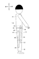
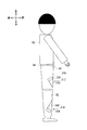
- FIG. 5 is a right side view for explaining the auxiliary tool 110 in which the attachment position of the artificial muscle portion is changed.
- the auxiliary tool 110 includes a front right artificial muscle portion 112 and a rear right artificial muscle portion 116.
- the front right artificial muscle portion 112 is attached to the front side of the right side surface of the shirt 80 and the trousers 82.
- the front right artificial muscle portion 112 includes a front right actuator 130 and a pair of front right attachment portions 132.
- the power wiring connecting the front right actuator 130 and the power supply unit 20 is omitted.
- the upper end of the front right actuator 130 is attached to the front side of the right side surface of the shirt 80 above the belt 84 via the front right attachment portion 132.
- the upper end of the front right actuator 130 may be attached to the belt 84.
- the lower end of the front right actuator 130 is attached to the front side of the right side surface of the trousers 82 below the knee via the front right attachment portion 132.
- the rear right artificial muscle portion 116 is attached to the rear side of the right side surface of the trousers 82.
- the rear right artificial muscle portion 116 includes a rear right actuator 142 and a pair of rear right attachment portions 144.
- the power wiring is omitted.
- the upper end of the rear right actuator 142 is attached to the rear side of the right side surface of the trousers 82 below the belt 84 via the rear right attachment portion 144.
- the upper end of the rear right actuator 142 may be attached to the shirt 80.
- the lower end of the rear right actuator 142 is attached to the rear side of the right side surface of the trousers 82 below the knee.
- the front left artificial muscle portion and the rear left artificial muscle portion are also attached to the left side surface.
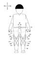
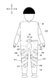
- FIG. 6 is a front view for explaining the auxiliary tool 210 in which the attachment position of the artificial muscle portion is changed.
- FIG. 7 is a right side view illustrating the auxiliary tool 210 in which the attachment position of the artificial muscle portion is changed.
- the assisting device 210 includes a first right artificial muscle portion 212, a first left artificial muscle portion 214, a second right artificial muscle portion 216, and a second left artificial muscle portion 218. Is provided.
- the first right artificial muscle portion 212 includes a first right actuator 230 and a pair of first right attachment portions 232.
- the upper end of the first right actuator 230 is attached to the right outer surface of the trousers 82 above the knee via the first right attachment portion 232. Note that the upper end of the first right actuator 230 may be attached to the belt 84 or the shirt 80.
- the lower end of the first right actuator 230 is attached to the inner surface on the right side of the trousers 82 below the knee via the first right attachment portion 232.
- a central portion of the first right actuator 230 is disposed on the front surface of the trousers 82.
- the second right artificial muscle portion 216 includes a second right actuator 242 and a pair of second right attachment portions 244.
- the lower end of the second right actuator 242 is attached to the right outer surface of the trousers 82 below the knee via the second right attachment portion 244.
- the upper end of the second right actuator 242 is attached to the inner surface on the right side of the trousers 82 above the knee via the second right attachment portion 244.
- the upper end of the second right actuator 242 may be attached to the belt 84 or the shirt 80.
- the center portion of the second right actuator 242 is disposed on the right front surface of the trousers 82.
- the first right actuator 230 and the second right actuator 242 intersect at the front side of the trousers 82 below the knee.
- the first right actuator 230 and the second right actuator 242 cross below the knee in the illustrated example.
- first left artificial muscle portion 214 includes a first left actuator 236 and a pair of first left attachment portions 238.
- the second left artificial muscle portion 218 includes a second left actuator 248 and a pair of second left attachment portions 250.
- the first left actuator 236 and the second left actuator 248 are attached by the first left attachment portion 238 and the second left attachment portion 250 so as to intersect at the front side on the left side of the trousers 82.
- the first left actuator 236 and the second left actuator 248 cross below the knee in the illustrated example.
- auxiliary tool 210 when the user moves forward, a voltage is applied to all of the first right actuator 230, the second right actuator 242, the first left actuator 236, and the second left actuator 248 to contract. At this time, the intersection of the first left actuator 236 and the second left actuator 248 and the intersection of the first right actuator 230 and the second right actuator 242 are respectively located below the knees. You can hook the intersection to the knee. Thereby, an upward force can be more effectively applied to the knee.
- auxiliary tool 210 when the user proceeds in the right direction, a voltage is applied to at least one of the first right actuator 230 and the second left actuator 248.
- auxiliary tool 210 when the user proceeds in the left direction, a voltage is applied to at least one of the second right actuator 242 and the first left actuator 236.
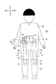
- FIG. 8 is a front view for explaining the auxiliary tool 310 in which the attachment position of the artificial muscle portion is changed.
- the auxiliary tool 310 includes a front right artificial muscle portion 312 and a front left artificial muscle portion 314.
- the upper end of the front right actuator 330 of the front right artificial muscle portion 312 is attached to the position of the belt 84 corresponding to the waist by the front right attachment portion 332 at the right side of the buckle 86.
- Under the front right actuator 330 it is attached to the position of the front surface of the trousers 82 corresponding to the foot by the front right attachment portion 332.
- the upper left of the front left actuator 336 of the front left artificial muscle portion 314 is attached to the position of the belt 84 corresponding to the waist by the front left attachment portion 338 on the left side of the buckle 86.
- the lower left of the front left actuator 336 of the front left artificial muscle portion 314 is attached to the front surface of the trouser 82 corresponding to the foot by the front left attachment portion 338.
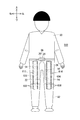
- FIG. 9 is a front view for explaining the auxiliary tool 410 in which the attachment of the artificial muscle portion is changed.
- the auxiliary tool 410 includes a right artificial muscle portion 412 and a left artificial muscle portion 414.
- the right artificial muscle portion 412 includes a right actuator 430 and a pair of right attachment portions 432.
- the upper end of the right actuator 430 is attached to the right front surface of the trousers 82 via the right attachment portion 432.
- the lower end of the right actuator 430 is attached to the right front surface of the trousers 82 via the right attachment portion 432.
- the right actuator 430 is attached to the trousers 82 so as to wind the right leg of the user and the right side of the trousers 82.
- the left artificial muscle portion 414 includes a left actuator 436 and a pair of left attachment portions 438.
- the left actuator 436 has an upper end and a lower end attached to the trousers 82 by the left attachment portion 438 so as to wind the left foot of the user and the left side of the trousers 82.
- the auxiliary tool 410 since the right actuator 430 and the left actuator 436 are wound around the right foot and the left foot, the user can exert more force than usual. Further, the user's force can be adjusted by controlling the winding force of the right actuator 430 and the left actuator 436.
- FIG. 10 is a front view for explaining the auxiliary tool 510 in which the attachment of the power supply unit 20 is changed.
- the auxiliary tool 510 further includes a holding part 570.
- the holding unit 570 holds the power supply unit 20, the mounting detection unit 26, and the control unit 28.
- the holding part 570 is attached so as to be movable along the belt 84. Thereby, the power supply unit 20, the mounting detection unit 26, and the control unit 28 can move along the belt 84 together with the holding unit 570.
- FIG. 11 is a front view for explaining the auxiliary tool 610 with the mounting portion changed.
- the auxiliary tool 610 includes a front right artificial muscle portion 612 and a front left artificial muscle portion 614.
- the front right actuator 630 of the front right artificial muscle portion 612 is sewn to the front surface of the trousers 82 by the front right attachment portion 632.
- the front left actuator 636 of the front left artificial muscle portion 614 is sewn to the front surface of the trouser 82 by the front left attachment portion 638.
- the clothes such as the trousers 82 to be sewn are preferably made of a material that can be stretched together with the front right actuator 630 and the front left actuator 636.
- the trousers 82 can be prevented from obstructing the expansion and contraction of the front right actuator 630 and the front left actuator 636.
- actuators may be provided.
- the right detection unit 22 and the left detection unit 24 output the acceleration of the right foot and the left foot, respectively, to detect the movement of the user.
- the other detection unit detects the movement of the other part of the user. You may make it do. Specifically, the movement of the user's right hand, left hand, waist, head, etc. may be detected by the detection unit.
- the actuator may be attached to another clothes.
- an actuator may be attached to an underwear, a garter belt, or the like.
- FIG. 12 is a front view of an auxiliary tool 710 that assists the upper body.
- FIG. 13 is a rear view of an auxiliary tool 710 that assists the upper body.
- the auxiliary tool 710 includes a right artificial muscle portion 712 and a left artificial muscle portion 714.
- the right artificial muscle portion 712 includes a right actuator 730 and a pair of right attachment portions 732.
- One right attachment portion 732 attaches the front end of the right actuator 730 to the shirt 80 below the right shoulder.
- the other right attachment portion 732 attaches the rear end of the right actuator 730 to the right portion of the belt 84.
- the left artificial muscle portion 714 includes a left actuator 736 and a pair of left attachment portions 738.
- One left attachment portion 738 attaches the front end of the left actuator 736 to a portion of the shirt 80 below the left shoulder.
- the other left attachment portion 738 attaches the rear end of the left actuator 736 to the left portion of the belt 84.
- the right actuator 730 and the left actuator 736 are attached across the user's shoulder.
- the auxiliary tool 710 can assist muscle strength when the user lifts something.
- the end of the actuator may be directly attached to the body with a band or the like through the attachment.
- the actuator may be a type that expands or contracts by applying a voltage, or a type that contracts.
- FIG. 14 is a front view of the user wearing the auxiliary tool 810. As shown in FIG. 14, the auxiliary tool 810 omits the right detection unit 22, the left detection unit 24, and the mounting detection unit 26 from the auxiliary tool 10 of FIG.
- the polymer materials included in the front right actuator 30, the front left actuator 36, the rear right actuator 42, and the rear left actuator 48 output an electromotive force when they are expanded and contracted by an external force.
- the front right actuator 30 is deformed by an external force resulting from the movement, generates an electromotive force, and outputs the electromotive force.
- the front right actuator 30 generates an electromotive force when it receives a load from the right foot of the user in a state where the voltage is applied from the power supply unit 20 to expand and contract.
- the working voltage that is the voltage acting on both ends of the front right actuator 30 is smaller than the applied voltage that is the voltage applied from the power supply unit 20.
- the front right actuator 30, the front left actuator 36, the rear right actuator 42, and the rear left actuator 48 are a front right working voltage, a front left working voltage, a rear right working voltage, and a rear that are voltages acting at both ends.
- the left working voltage is output to the control unit 828.
- the front right working voltage, the front left working voltage, the rear right working voltage, and the rear left working voltage include an electromotive force and a voltage applied from the power supply unit 20.
- FIG. 15 is a block diagram for explaining a control system of the auxiliary tool 810.
- the control unit 828 includes a processing unit 860 and a storage unit 62.
- the processing unit 860 functions as the acquisition unit 64, the calculation unit 866, and the power supply control unit 68 by reading the auxiliary tool control program stored in the storage unit 62.
- the acquisition unit 64 includes a front right working voltage, a front left working voltage, and a rear right working voltage, which are voltages acting on both ends of the front right actuator 30, the front left actuator 36, the rear right actuator 42, and the rear left actuator 48. And the rear left working voltage is obtained.
- the acquisition unit 64 outputs each working voltage to the calculation unit 866. It should be noted that the operating voltages in the state where the applied voltage is not applied to the front right actuator 30, the front left actuator 36, the rear right actuator 42 and the rear left actuator 48 from the power supply unit 20 are the front right actuator 30 and the front left actuator 36.
- the electromotive force generated in the rear right actuator 42 and the rear left actuator 48 are the front right actuator 30 and the front left actuator 36.
- the calculating unit 866 acquires each working voltage or electromotive force from the acquiring unit 64.
- the calculating unit 866 applies the front right applied voltage, the front left applied voltage, and the rear right applied voltage applied to each of the front right actuator 30, the front left actuator 36, the rear right actuator 42, and the rear left actuator 48 from the power supply control unit 68. And the back left applied voltage is acquired.
- the calculating unit 866 compares each applied voltage and each working voltage individually, and the front right electromotive force generated by the external force acting on the front right actuator 30, the front left actuator 36, the rear right actuator 42, and the rear left actuator 48.
- the front left electromotive force, the rear right electromotive force, and the rear left electromotive force are calculated.
- the external force acts by, for example, the user bending and stretching the foot.
- the calculation unit 866 calculates the amount of front right expansion / contraction of the front right actuator 30, the front left actuator 36, the rear right actuator 42, and the rear left actuator 48 that are expanded / contracted according to the external force acting by the user's movement from the calculated electromotive forces.
- the left expansion amount, the rear right expansion amount, and the rear left expansion amount are calculated.
- the front right expansion amount, front left expansion amount, rear right expansion amount and rear left expansion amount are only the expansion amounts corresponding to the electromotive force, and are examples of calculated values.
- the calculation unit 866 calculates and determines the moving direction and stop of the movement of the right foot and the left foot by the user based on each expansion / contraction amount calculated from the electromotive force.
- the calculation unit 866 generates a right movement signal and a left movement signal based on the movement direction and stop of each of the right foot and the left foot, and outputs them to the power supply control unit 68.
- the power supply control unit 68 controls the power supply unit 20 based on the right movement signal and the left movement signal corresponding to the expansion / contraction amount calculated by the calculation unit 866. As a result, the power supply unit 20 supplies power to one of the front right actuator 30, the front left actuator 36, the rear right actuator 42, and the rear left actuator 48, or stops supplying power.
- FIG. 16 is a flowchart of auxiliary tool control processing executed by the auxiliary tool 810.
- the auxiliary tool control process is executed by the processing unit 860 reading the auxiliary tool control program stored in the storage unit 62.
- the acquisition unit 64 acquires the electromotive forces of the front right actuator 30, the front left actuator 36, the rear right actuator 42, and the rear left actuator 48, and then proceeds to the calculation unit 866.
- the calculation unit 866 determines whether the user has moved based on the acquired electromotive force (S112). If the calculation unit 866 determines that the acquired electromotive force is “0” and the user is not moving (S112: No), steps S110 and S112 are repeated.
- the calculating unit 866 calculates the amount of expansion / contraction of the front right actuator 30, the front left actuator 36, the rear right actuator 42, and the rear left actuator 48 from the electromotive force. (S114).
- the calculating unit 866 calculates the moving direction of the right foot and the left foot from the amount of expansion / contraction (S116).
- the calculation unit 866 outputs a right movement signal and a left movement signal corresponding to the calculated movement direction to the power supply control unit 68 (S118).
- the power supply control unit 68 controls the power supply unit 20 according to the right movement signal and the left movement signal acquired from the calculation unit 866, and the front right actuator 30, the front left actuator 36, the rear right actuator 42, and the rear Electric power is supplied to the left actuator 48 (S120).
- the power control unit 68 when the power control unit 68 acquires a right movement signal indicating that the right foot is moving forward, the power control unit 68 supplies power to the front right actuator 30 from the power supply unit 20. As a result, the applied voltage is applied to the front right actuator 30 by the power supply unit 20.
- An example of the applied voltage is a maximum voltage at which the front right actuator 30 can exert the maximum stretching force.
- the front right actuator 30 contracts and raises the right foot forward.
- the power supply control unit 68 may cause the rear right actuator 42 to supply power and expand the power, or may not supply power.
- the power supply control unit 68 does not supply power to other actuators.
- the power supply control unit 68 acquires a left movement signal indicating that the left foot is rising backward, the power supply unit 68 supplies power to the rear left actuator 48 from the power supply unit 20. As a result, the rear left actuator 48 contracts and raises the left foot backward. In this case, the power supply control unit 68 may cause the front left actuator 36 to supply power and expand the power, or may not supply power. The power supply control unit 68 does not supply power to other actuators.
- the calculation unit 866 acquires the value of the working voltage acting on the front right actuator 30, the front left actuator 36, the rear right actuator 42, and the rear left actuator 48 via the acquisition unit 64. In addition, the calculation unit 866 acquires the value of the applied voltage applied by the power supply unit 20 to the front right actuator 30, the front left actuator 36, the rear right actuator 42, and the rear left actuator 48 from the power supply control unit 68 (S122). .
- the calculation unit 866 calculates the electromotive force generated in each of the front left actuator 36, the rear right actuator 42, and the rear left actuator 48 that are expanded and contracted by the user's movement from the acquired working voltage and applied voltage (S124). .
- the calculation unit 866 determines whether the user's movement is stopped based on the calculated electromotive force (S126). If the calculation unit 866 determines that the user's movement has not stopped (S126: No), the calculation unit 866 repeats the processing from step S114 onward, and changes the front left actuator 36, the rear right actuator 42, and the rear left actuator 48 to the user's movement. Combine and extend.
- the calculation unit 866 determines that the user's movement has stopped after the threshold time has elapsed with all the electromotive forces being constant (S126: Yes)
- the calculation unit 866 outputs a stop signal to the power supply control unit 68.
- the power supply control unit 68 stops the supply of power applied to the front left actuator 36, the rear right actuator 42, and the rear left actuator 48 (S128).
- the auxiliary tool 810 includes the front right actuator 30, the front left actuator 36, the rear right actuator 42, and the rear left actuator 48 that expand and contract by applying a voltage and output an electromotive force by expanding and contracting with an external force. ing.
- the auxiliary tool 810 can assist the user's movement by the front right actuator 30, the front left actuator 36, the rear right actuator 42, and the rear left actuator 48, and can calculate and determine the user's movement. Therefore, the auxiliary tool 810 can simplify the configuration.
- auxiliary tool 810 can assist and calculate the movement of the user at the same place by the front right actuator 30, the front left actuator 36, the rear right actuator 42, and the rear left actuator 48, the user movement more appropriately. Can assist.
- the right detection unit 22, the left detection unit 24, the front right actuator 30, the front left actuator 36, the rear right actuator 42, and the rear left actuator 48 that function as a detection unit are used to move the user.
- these detection units may detect information other than the user's movement.
- the detection unit may detect a change in the user's body such as the position of a specific part of the user's body, the user's muscle strength, and output a detection signal corresponding to the change in the body.
- the detection unit may detect a change in the user's body such as the position of a specific part of the user's body, the user's muscle strength, and output a detection signal corresponding to the change in the body.
- the power supply control unit 68 compares the reference value with the detection signals output by the front right actuator 30, the front left actuator 36, the rear right actuator 42, and the rear left actuator 48 functioning as a detection unit, and compares the reference signals with the front right actuator 30.
- the power supply unit 20 that supplies power to the front left actuator 36, the rear right actuator 42, and the rear left actuator 48 is controlled.
- an example of the reference value is preset and stored in the storage unit 62.
- the reference value is set and stored from information such as the user's step length detected in advance and the height of the foot raised during walking.
- the reference value is set by the calculation unit 866 based on information detected by the detection unit such as the front right actuator 30.
- the detection unit such as the front right actuator 30 detects a part of the user's body when the user starts moving, or the user's muscle strength, and outputs the detected part to the calculation unit 866.
- the detection unit such as the front right actuator 30 detects the movement of the user's foot or the change in muscle strength for a few steps.
- the calculation unit 866 calculates an average value from the movement of the user's foot acquired from the detection unit such as the front right actuator 30 and stores the average value in the storage unit 62 as a reference value.
- the calculation unit 866 sets a reference value in association with each of the users and stores the reference value in the storage unit 62.
- the power supply control unit 68 sets voltage values to be applied to the front right actuator 30, the front left actuator 36, the rear right actuator 42 and the rear left actuator 48 from the reference values stored in the storage unit 62.
- the power supply control unit 68 continues to control with the voltage value regardless of the information detected by the detection unit such as the front right actuator 30 after the setting.
- the power supply control unit 68 may compare the information detected by the detection unit such as the front right actuator 30 with the reference value and change the voltage value so as to approach the reference value. In this case, the power supply control unit 68 may acquire information detected from the detection unit at all times, or may acquire information from the detection unit at a predetermined time interval.
- the power supply control unit 68 sets the voltage value so as to provide an auxiliary force at a preset ratio with respect to the user's muscle strength.
- an example of the preset ratio is several% to several tens%.
- the calculation unit 866 may update the reference value. For example, when the number of times the user's muscle strength or the like achieves the reference value is equal to or less than a predetermined threshold ratio, the calculation unit 866 may decrease the reference value.
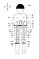
- FIG. 17 is a front view of a user wearing the auxiliary tool 910.
- FIG. 18 is a rear view of the user wearing the auxiliary tool 910.
- the same reference numerals are given to the same elements as those in FIG. 17 and FIG. 18, the same reference numerals are given to the same elements as those in FIG. 17 and FIG. 18, the same reference numerals are given to the same elements as those in FIG. 17 and FIG. 18, the same reference numerals are given to the same elements as those in FIG.
- the artificial muscle portion 912 and the artificial muscle portion 914 have an attachment portion 932 at the upper end in the extension / contraction direction and an attachment portion 934 at the lower end in the extension / contraction direction.
- the attachment portion 932 has a cylindrical shape.
- the attachment portion 932 includes an anode and a cathode. By attaching the attachment portion 932, the artificial muscle portions 912 and 914 are attached, and the actuators 916 and 918 and the power source are electrically connected.
- the attachment portion 934 has a ring shape, and the artificial muscle portions 912 and 914 are attached to the shirt 80 or the trousers 82 by locking the ring portion.
- the front surface of the shirt 80 has four attached portions 960, and the rear surface has two locking portions 966. Further, the front surface of the trouser 82 has two locking portions 966, and the rear surface has two locking portions 966 and two attached portions 960. Note that an example of attaching the attached portion 960 and the locking portion 966 to the shirt 80 or the like is stitching, but is not limited thereto, and may be attached by adhesion, or may be fixed to the shirt 80 or the like by other members. Alternatively, the shirt 80 or the like may be sandwiched between other members and fastened to the body.
- the attached portion 960 is the front surface of the shirt 80 and is provided on the left and right sides of the abdomen and chest. Moreover, the to-be-attached part 960 is the rear surface of trousers 82, Comprising: It is provided also in the base part of a right-and-left leg.
- the attached portion 960 has a concave shape so that the attaching portion 932 is attached.
- the attached portion 960 has terminals corresponding to the anode and the cathode of the attaching portion 932, and electrically connects the terminal and the power source by connecting the terminal and the power wirings 34 and 40.
- the attached portion 960 and the power wirings 34 and 40 are detachably connected.
- the latching portion 966 is provided on the rear surface of the shirt 80 and on the left and right sides of the waist.
- the locking portion 966 has a plurality of mounting hooks 965 arranged in the vertical direction.
- the attachment hook 965 has a ring shape and has a part that is partially cut away. Note that the notched portion of the attachment hook 965 may be provided with a structure that moves only inside the ring to prevent the member locked to the attachment hook 965 from easily coming off.
- the locking portion 966 has three mounting hooks 965 arranged vertically. Further, the locking portion 966 is provided on the front surface of the trousers 82, below the knees of the left and right feet, and on the rear surface of the trousers 82, and also in the vicinity of the ankles of the left and right feet. Note that the attachment hook 965 is also an example of a portion to be attached to which the attachment portion 932 is attached.
- the belt 84 has a buckle 986 disposed on the front surface of the fuselage.
- the buckle 986 is removably attached from the belt 84. Therefore, by removing the buckle 986, the power wirings 34, 40, the right detector 22 and the left detector 24 connected to the buckle 986 are removed from the belt 84. The power wirings 34 and 40, the right detection unit 22 and the left detection unit 24 may be detached from the buckle 986, respectively.
- the attachment portion 932 is attached to the attachment portion 960 by being inserted into the attachment portion 960, and the upper end of the artificial muscle portion 912 is positioned and fixed to the shirt 80. That is, the attachment portion 932 also serves as a positioning unit that positions the artificial muscle portion 912.
- the attachment portion 934 is attached to the attachment hook 965 by being engaged with the attachment hook 965 of the engagement portion 966, and the lower end of the artificial muscle portion 912 is positioned and fixed to the pants 82. That is, the attachment portion 934 also serves as a positioning means for positioning the artificial muscle portion 912.
- the upper and lower ends of the artificial muscle portion 912 are positioned and fixed to the shirt 80 or the like by the attachment portions 932 and 934.
- the artificial muscle part 912 is attached to the auxiliary tool 910.
- the attachment of the artificial muscle part 914 is the same as the artificial muscle part 912, description is abbreviate
- locking part 966 is not restricted to the structure mentioned above, A fastener, a hook-and-loop fastener, and a buckle may be sufficient.
- the attachment portions 932 and 934 serve as positioning means, when the user attaches the actuator to the auxiliary tool 910 again, the attachment portions 932 and 934 are attached without being displaced from the position where the assist force is appropriately generated.
- the positioning means may be a fastener, a magnet, a hook, or a buckle.
- hook-and-loop fasteners are used for the attachment portion 932 and the attachment portion 960, a line or a figure for guiding the attachment position may be displayed on the surface of the shirt 80 or the like.
- the positioning means is provided in the attachment portions 932 and 934, but may be provided in a portion different from the attachment portions 932 and 934.
- the attaching part 932 removes the upper end of the artificial muscle part 912 from the shirt 80 by detaching from the attached part 960.
- the attachment portion 932 can be detached from the auxiliary tool 910 together with the artificial muscle portion 912 that is an actuator.
- the attachment portion 934 removes the lower end of the artificial muscle portion 912 from the trousers 82 by releasing the engagement of the engagement portion 966 with the attachment hook 965.
- the attachment portion 934 can be detached from the auxiliary tool 910 together with the artificial muscle portion 912 that is an actuator.
- the upper and lower ends of the artificial muscle portion 912 are removed from the shirt 80 and the like by the attachment portions 932 and 934. Thereby, the artificial muscle part 912 is removed from the auxiliary tool 910. Since the removal of the artificial muscle portion 914 is the same as that of the artificial muscle portion 912, the description is omitted.
- FIG. 19 is a front view of the user with the artificial muscle portion of the auxiliary tool 910 removed.
- the artificial muscle portion 912, the artificial muscle portion 914, the power wirings 34 and 40, the right detection portion 22, the left detection portion 24, and the buckle 986 are included in a shirt. 80 and pants 82 can be removed. Thereby, the user can wash the shirt 80 or the trousers 82 when the shirt 80 or the trousers 82 becomes dirty.
- FIG. 20 is a front view of the user in a state where the attachment position of the artificial muscle portion is changed.
- the attachment portion 934 of the artificial muscle portion 912 is engaged with an attachment hook 965 located at the center in the vertical direction of the engagement portion 966. Since the contraction direction of the artificial muscle portion 912 is the vertical direction, the auxiliary force applied to the user of the artificial muscle portion 912 can be adjusted by changing the vertical position of the attachment hook 965 to which the attachment portion 932 is attached. For example, when the attachment portion 934 is locked to the attachment hook 965 positioned at the top, the artificial muscle portion 912 is slackened.
- the assisting force of the artificial muscle portion 912 is larger when there is no slack than when there is slack. Therefore, by changing the position of the attachment hook 965 to which the attachment portion 932 is attached in a direction along the contraction direction of the artificial muscle portion 912, the assisting force that the artificial muscle portion 912 gives to the user can be adjusted.
- the artificial muscle portion 912 can be attached to the attachment portion 960 attached to the chest of the shirt 80, and the attachment portion 934 can be attached to the engaging portion 966 attached to the back waist. Thereby, the artificial muscle part 912 can also change the user's part to which the assisting force is applied or the direction in which the assisting force is applied. In addition, the artificial muscle part 912 can be attached also to the rear surface of the trousers 82 by the method described above.
- FIG. 21 is a front view of the user with the fixed part attached.
- the attached portion 962 has a fixing portion 954.
- the fixing portion 954 is connected to the two attached portions 962, and is fastened to the user's waist by the fixing portion 954 so that the position of the attached portion 960 is fixed so as not to deviate from the user's body.
- An example of the fixing portion 954 is an elastic belt.
- the shape and function of the attached portion 962 are the same as those of the attached portion 960, description thereof is omitted.
- the locking portion 968 has a fixing portion 956.
- the fixing portion 956 is connected to the locking portion 968, and is fixed to the user's shin portion by the fixing portion 956 so that the position of the locking portion 968 does not deviate from the user's body.
- An example of the fixing portion 956 is an elastic belt. Note that the shape and function of the locking portion 968 are the same as those of the locking portion 966, and a description thereof will be omitted.
- the fixing portion 954 is connected to the two attached portions 962, but the fixing portion 954 is not connected to the attached portion 962 and may be a separate body. Good. In the case where the fixing portion 954 is a separate body, the fixing portion 954 prevents the position of the attached portion 962 from shifting by tightening the user's waist while sandwiching the attached portion 962.
- the fixing portion 954 may be provided on a part of the shirt 80 or the trousers 82.
- the fixing portion 954 is made of a highly elastic material.
- the fixing part 954 provided in a part of the shirt 80 or the trousers 82 is connected to the attached part 962 and tightens the fixing part 954 to the user's body. Thereby, the to-be-attached part 962 is fixed to a user's body.
- FIG. 22 shows an example of the attaching part and the attached part.
- the attachment portion 932 has a cylindrical portion 948, and an anode terminal 940 and a cathode terminal 942 are provided at the ends thereof.
- the anode terminal 940 is connected to the anode of the actuator 916, and the cathode terminal 942 is connected to the cathode of the actuator 916.
- the attached portion 960 has a concave shape 950 that is complementary to the cylindrical portion 948 of the attaching portion 932. Furthermore, a cylindrical recess 944 corresponding to the anode terminal 940 and a conical recess 946 are provided on the bottom surface of the recess 950. The cylindrical recess 944 is connected to the anode wiring in the power wiring 34, and the conical recess 946 is connected to the cathode wiring in the power wiring 34.
- the anode terminal 940 of the mounting portion 932 can be inserted into the cylindrical recess 944 of the mounted portion 960, but the corner of the anode terminal 940 and the conical slope portion interfere with the conical recess 946. Can't insert.
- the cathode terminal 942 can be inserted into the cylindrical recess 944 and the conical recess 946, but cannot be electrically connected because the length of the cylindrical recess 944 is long. Therefore, in attaching the attachment portion 932 and the attachment portion 960, the anode terminal 940 and the cathode terminal 942 of the attachment portion 932 have a structure that prevents erroneous connection.
- anode terminal 940, the cathode terminal 942, the cylindrical recess 944, and the conical recess 946 are examples of connection portions that electrically connect the attached portion 960 included in the shirt 80 and the actuator 916 that is an actuator. .
- the misconnection prevention structure has shown an example in which the shapes of the anode and the cathode are different, but the shape is not limited to the cylinder and the cone, and the cross-sectional shape, length, and thickness are made different. May be. Moreover, it is good also as an incorrect connection prevention structure by making the insertion shape of a terminal into an asymmetrical shape.
- the terminals may be easily connected to each other by not providing the attachment portion 932 and the attachment portion 960 with a structure that prevents erroneous connection.
- the attachment portion 932 has an example having the cylindrical portion 948.
- a part of the cylindrical portion 948 is cut into a D shape, and the concave shape 950 is also a concave shape complementary to the D shape. It is good. Thereby, since the connection phase is determined by the D shape, erroneous connection can be prevented.
- the attaching portion 932 is attached to the attached portion 960, and the artificial muscle portion 912 is attached to the shirt 80 or the like.
- the present invention is not limited to the above configuration, and the attached portion 960 is detachable from the shirt 80 or the like, and the artificial muscle portion 912, the artificial muscle portion 914, the power wiring 34, the attachment portion 932 and the attached portion 960 are connected.
- 40 and the buckle 986 may be integrally removed from the shirt 80 or the like. In that case, it is not necessary to provide an attachment part and a to-be-attached part.
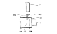
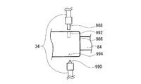
- FIG. 23 shows an example of a connection configuration between the power wiring and the buckle.
- the buckle 986 and the power wirings 34 and 40 may be detachably connected.
- the power wiring 34 and the like have an anode terminal 988 and a cathode terminal 990.
- the anode terminal 988 has a cylindrical shape like the anode terminal 940.
- the cathode terminal 990 has a conical shape like the cathode terminal 942.
- a cylindrical recess is provided in the anode terminal 992 of the buckle 986, and a conical recess is provided in the cathode terminal 994. Accordingly, it is possible to prevent the anode terminal 988 from being connected to the cathode terminal 994 and the cathode terminal 990 from being connected to the anode terminal 992.
- FIG. 24 shows another example of the connection configuration between the power wiring and the buckle.
- the power wiring 34 and the like are divided into an anode wiring and a cathode wiring.
- the anode terminal 992 of the buckle 986 is disposed on the upper side
- the cathode terminal 994 is disposed on the lower side.
- the upper connection method may be a hook method
- the lower connection method may be an insertion method to prevent erroneous connection by changing the connection method.
- auxiliary tools 12 anterior right artificial muscle part, 14 anterior left artificial muscle part, 16 posterior right artificial muscle part, 18 posterior left artificial muscle part, 20 power supply part, 22 right detection part, 24 left detection part, 26 attachment detection part 28 control section, 30 front right actuator, 32 front right mounting section, 34 power wiring, 36 front left actuator, 38 front left mounting section, 40 power wiring, 42 rear right actuator, 44 rear right mounting section, 46 power wiring, 48 rear left actuator, 50 rear left mounting section, 52 power wiring, 54 wiring, 56 wiring, 60 processing section, 62 storage section, 64 acquisition section, 66 determination section, 68 power control section, 80 shirt, 82 pants, 84 belt , 86 buckle, 88 pockets, 110 auxiliary equipment, 112 front right artificial muscle part, 116 rear right artificial muscle part, 13 Front right actuator, 132 Front right mounting part, 142 Rear right actuator, 144 Rear right mounting part, 210 Auxiliary tool, 212 First right artificial muscle part, 214 First left artificial muscle part, 216 Second right artificial muscle part, 218 2nd left artificial muscle part,
Landscapes
- Health & Medical Sciences (AREA)
- Engineering & Computer Science (AREA)
- Animal Behavior & Ethology (AREA)
- Life Sciences & Earth Sciences (AREA)
- Veterinary Medicine (AREA)
- Public Health (AREA)
- General Health & Medical Sciences (AREA)
- Epidemiology (AREA)
- Pain & Pain Management (AREA)
- Physical Education & Sports Medicine (AREA)
- Rehabilitation Therapy (AREA)
- Mechanical Engineering (AREA)
- Robotics (AREA)
- Chemical & Material Sciences (AREA)
- General Chemical & Material Sciences (AREA)
- Chemical Kinetics & Catalysis (AREA)
- Manipulator (AREA)
- Rehabilitation Tools (AREA)
Abstract
身体の動作を補助する補助用具であって、身体に取り付ける装着部と、電圧が印加されると伸長または収縮する高分子材料を含むアクチュエータと、アクチュエータを装着部に取り付ける取付部とを備え、取付部は、前記アクチュエータとともに取り外し可能に取り付けられ、装着部におけるアクチュエータの位置を位置決めする位置決め手段が設けられている。
Description
本発明は、補助用具に関する。
ユーザの筋力を補助する補助用具が知られている(例えば、特許文献1参照)。
[特許文献1] 特開2003-153928号公報
[特許文献1] 特開2003-153928号公報
上述の補助用具は、衣服のように装着できるので、汚れた場合に洗濯できることが好ましい。しかし、電圧を印加して動作するアクチュエータを用いた補助用具の場合、容易に洗濯が行えないとの課題がある。
本発明の第1の態様においては、身体の動作を補助する補助用具であって、身体に取り付ける装着部と、電圧が印加されると伸長または収縮する高分子材料を含むアクチュエータと、アクチュエータを前記装着部に取り付ける取付部とを備え、取付部は、アクチュエータとともに取り外し可能に取り付けられる。
なお、上記の発明の概要は、本発明の必要な特徴の全てを列挙したものではない。また、これらの特徴群のサブコンビネーションもまた、発明となりうる。
以下、発明の実施の形態を通じて本発明を説明するが、以下の実施形態は請求の範囲にかかる発明を限定するものではない。また、実施形態の中で説明されている特徴の組み合わせの全てが発明の解決手段に必須であるとは限らない。
図1は、補助用具10を装着したユーザの正面図である。図2は、補助用具10を装着したユーザの背面図である。図1に矢印で示す上下左右を補助用具10の上下左右方向とする。また、ユーザから見て前後を、補助用具10の前後方向とする。
ユーザは、上半身にシャツ80を着るとともに、下半身にズボン82を履いているとする。また、ズボン82の胴体の腰部分には、ベルト84が巻かれている。ベルト84は、胴体の前面に配されるバックル86を有する。シャツ80の上部は、肩からずれないように形成されている。ズボン82の裾は、足首からずれないように絞られている。尚、シャツ80及びズボン82の内面が、ユーザの体と密着するダイビングスーツのような構成であってもよい。シャツ80、ズボン82、及び、ベルト84は、身体に取り付ける装着部の一例である。更に、ベルト84は、身体に固定されている装着部の部分の一例である。
補助用具10は、ユーザの身体の動作を補助する。図1及び図2に示すように、補助用具10は、前右人工筋肉部12と、前左人工筋肉部14と、後右人工筋肉部16と、後左人工筋肉部18と、電源部20と、検出部の一例である右検出部22及び左検出部24と、装着検出部26と、制御部28とを備える。
前右人工筋肉部12は、前右アクチュエータ30と、一対の前右取付部32と、電力配線34とを備える。
前右アクチュエータ30は、上下方向に延びるように形成されている。前右アクチュエータ30の上下方向、即ち、長手方向の一端は、右足の上方であって、ベルト84及びユーザの腰の上方のシャツ80の前面に配置されている。前右アクチュエータ30の長手方向の他端は、右足の膝の下方のズボン82の前面に配置されている。前右アクチュエータ30は、ユーザの胴体の腰及び膝の関節を跨ぐように設けられている。
前右アクチュエータ30は、電圧が印加されると伸縮する高分子材料を含む。前右アクチュエータ30は、電圧が印加されると、上下方向、即ち、長手方向に伸縮する。これにより、前右アクチュエータ30は、収縮することにより、歩くとき等のユーザの右足の上昇を補助する。
高分子材料の一例は、ポリロタキサン架橋体である。前右アクチュエータ30は、平面状のポリロタキサン架橋体の両面を伸縮性の電極で挟んだシート部材を巻くことによって作製される。ここで、前右アクチュエータ30の長手方向は、巻かれたシート部材の軸方向と平行である。前右アクチュエータ30は、柔軟性を有するので、着用した状態で歩行したときのユーザの違和感を低減できる。
高分子材料の別例は、ポリピロール膜である。電解液中に浸漬されたポリピロール膜は、電圧が印加されることにより、膨張または収縮する。例えば、正の電圧が印加されると、ポリピロール膜は膨張する。負の電圧が印加されると、ポリピロール膜は収縮する。尚、前右アクチュエータ30がポリピロール膜を含む場合、電解液が必要となるので、前右アクチュエータ30を封止する必要がある。
高分子材料の別例は、ポリ塩化ビニル(PVC)ゲルである。導電材からなるメッシュ体と、メッシュ体を挟む位置に対向配置された第1のPVCゲルと第2のPVCゲルと、第1のPVCゲルと第2のPVCゲルのそれぞれの外面に接して設けられた第1の電極と、第2の電極とからなる。メッシュ体との間に電圧を印加しない状態では、第1および第2のPVCゲルの対向面が離間するが、メッシュ体を陽極に、第1および第2の電極を陰極に接続して、メッシュ体と第1および第2の電極との間に電圧を印加すると、第1および第2のPVCゲルの一部がメッシュ体のメッシュ孔に入り込み、厚さ方向に変位する。尚、PVCはゲルを構成する材料の一例であり、ポリメタクリル酸メチル、ポリウレタン、ポリスチレン、ポリ酢酸ビニル、ナイロン6等の誘電性高分子材料を用いてもよい。また、PVCゲルから成るアクチュエータを積層させて、アクチュエータの出力を向上させてもよい。この場合、個々のアクチュエータのメッシュ体が陽極に接続され、第1および第2の電極が各々陰極に接続される。
一対の前右取付部32は、前右アクチュエータ30の伸縮方向の両端を服に取り付ける。一方の前右取付部32は、前右アクチュエータ30の上端部に設けられ、シャツ80の前面に取り付けられている。尚、前右アクチュエータ30の上端部は、一方の前右取付部32を介して、伸縮力により動きにくいベルト84に取り付けられていてもよい。このように、身体に固定されたベルト84に取り付けることにより、前右取付部32は、伸縮時の支点となる前右アクチュエータ30の上端部を確実に支持できる。他方の前右取付部32は、前右アクチュエータ30の下端部に設けられ、ズボン82の前面に取り付けられている。前右取付部32は、ボタン、チャック、マジックテープ(登録商標)等によってシャツ80またはズボン82に、前右アクチュエータ30とともに取り外し可能に取り付けられている。一対の前右取付部32の一部は、ゴム等の弾性部材で構成することが好ましい。
電力配線34の一端は、上側の前右取付部32を介して、前右アクチュエータ30と電気的に接続されている。電力配線34の他端は、電源部20に接続されている。これにより、電力配線34は、前右アクチュエータ30と電源部20とを電気的に接続する。
前左人工筋肉部14、後右人工筋肉部16及び後左人工筋肉部18は、前右人工筋肉部12と同様の構成を有するので、異なる点以外は説明を省略する。
前左人工筋肉部14は、前左アクチュエータ36と、一対の前左取付部38と、電力配線40とを備える。前左アクチュエータ36は、一対の前左取付部38によって、腰の上方のシャツ80の前面から左足の膝の下方にわたってズボン82の前面に取り付けられている。尚、前左アクチュエータ36の一端は、伸縮力により動きにくいベルト84に取り付けてもよい。前左アクチュエータ36は、収縮することにより、歩くとき等のユーザの左足の上昇を補助する。電力配線40は、前左アクチュエータ36と電源部20とを電気的に接続する。
後右人工筋肉部16は、後右アクチュエータ42と、一対の後右取付部44と、電力配線46とを備える。後右アクチュエータ42は、一対の後右取付部44によって、右足の付け根のズボン82の後面から右足の膝の下方の足首近傍にわたってズボン82の後面に取り付けられている。後右アクチュエータ42は、ベルト84及びシャツ80等に取り付けてもよい。また、後右アクチュエータ42は、膝下までの長さであってもよい。後右アクチュエータ42は、ズボン82のポケット88の内部に配置されている。ポケット88は、後右アクチュエータ42の伸縮とともに、伸縮できる材料が好ましい。これにより、ポケット88が後右アクチュエータ42の伸縮の妨げとなることを防ぐことができる。また、ポケット88が伸縮方向と交差する方向の後右アクチュエータ42の変形を防ぐことができる。後右アクチュエータ42は、収縮することにより、ボールを蹴るとき等のユーザの右足の上昇を補助する。電力配線46は、ベルト84の裏に配置された配線を介して、後右アクチュエータ42と電源部20とを電気的に接続する。
後左人工筋肉部18は、後左アクチュエータ48と、一対の後左取付部50と、電力配線52とを備える。後左アクチュエータ48は、一対の後左取付部50によって、左足の付け根のズボン82の後面から左足の膝の下方の足首近傍にわたってズボン82の後面に取り付けられている。後左アクチュエータ48は、ベルト84及びシャツ80等に取り付けてもよい。また、後左アクチュエータ48は、膝下までの長さであってもよい。ポケット88は、後左アクチュエータ48の伸縮とともに、伸縮できる材料が好ましい。後左アクチュエータ48は、ズボン82のポケット88の内部に配置されている。後左アクチュエータ48は、収縮することにより、ボールを蹴るとき等のユーザの左足の上昇を補助する。電力配線52は、ベルト84の裏に配置された配線を介して、後左アクチュエータ48と電源部20とを電気的に接続する。
電源部20は、ベルト84のバックル86に設けられている。電源部20は、前右アクチュエータ30、前左アクチュエータ36、後右アクチュエータ42及び後左アクチュエータ48と電力を供給可能に電気的に接続されている。
右検出部22は、ユーザの右足の膝の近傍に設けられている。右検出部22は、ユーザの右足の動きに対応する加速度を検出する。右検出部22の一例は、3軸加速度センサである。右検出部22は、配線54を介して、制御部28と電気的に接続されている。右検出部22は、ユーザの右足の動き及び加速度に対応する右加速度信号を制御部28へと出力する。右加速度信号は、検出信号の一例である。
左検出部24は、ユーザの左足の膝の近傍に設けられている。左検出部24は、3軸加速度センサであって、ユーザの左足の動きに対応する加速度を検出する。左検出部24は、ユーザの左足の動き及び加速度に対応する左加速度信号を、配線56を介して制御部28へと出力する。左加速度信号は、検出信号の一例である。
装着検出部26は、ベルト84のバックル86に設けられている。装着検出部26の一例は、圧力センサである。装着検出部26は、ベルト84の装着を判定する圧力を検出する。装着検出部26は、制御部28と電気的に接続されている。装着検出部26は、ベルト84がユーザに装着されて、ベルト84に圧力が作用すると、当該圧力に対応する圧力信号を制御部28に出力する。
制御部28は、補助用具10の制御全般を司る。制御部28の一例は、コンピュータである。
図3は、補助用具10の制御系を説明するブロック図である。図3に示すように、制御部28は、処理部60と、格納部62とを備える。処理部60は、格納部62に格納された補助用具制御プログラムを読み込むことにより、取得部64、判定部66、及び、電源制御部68として機能する。
取得部64は、右検出部22及び左検出部24から右加速度信号及び左加速度信号を取得する。取得部64は、装着検出部26から圧力信号を取得する。取得部64は、取得した加速度信号及び圧力信号を判定部66へと出力する。
判定部66は、取得部64から右加速度信号及び左加速度信号を取得する。判定部66は、右加速度信号に基づいて右足の速度である右速度を算出する。判定部66は、算出した右速度の正負から右足の移動方向、速さ及び停止を判定する。判定部66は、算出した右速度を積算することにより、右足が最も上昇した位置である右最上位置を検出する。判定部66は、左加速度信号から左足の速度である左速度を算出する。判定部66は、左速度から左足の移動方向、速さ、及び、停止を判定する。判定部66は、算出した左速度を積算することによって、左足が最も上昇した位置である左最上位置を検出する。判定部66は、検出した右最上位置及び左最上位置を格納部62に格納する。
判定部66は、取得部64から圧力信号を取得する。判定部66は、圧力信号からベルト84に作用している圧力を検出して、ベルト84がユーザに装着されているか、または、装着されていないかを判定する。判定部66は、ベルト84が装着されていると判定すると、右加速度信号及び左加速度信号に基づいて検出した右足及び左足の上昇、下降、停止を示す右移動信号及び左移動信号を電源制御部68へと出力する。右移動信号及び左移動信号に上昇、下降の速さを含めてもよい。
電源制御部68は、ベルト84が装着された場合、判定部66が右加速度信号及び左加速度信号に基づいて検出した右移動信号及び左移動信号によって、電源部20を制御する。これにより、電源部20は、ベルト84が装着された場合に、前右アクチュエータ30、前左アクチュエータ36、後右アクチュエータ42及び後左アクチュエータ48のいずれかに電力を供給、または、電力の供給を停止する。
図4は、補助用具10によって実行される補助用具制御処理のフローチャートである。補助用具制御処理は、格納部62に格納された補助用具制御プログラムを処理部60が読み込むことによって実行される。
図4に示すように、補助用具制御処理では、まず、取得部64が装着検出部26から圧力信号を取得して、判定部66へと出力する(S10)。判定部66は、取得した圧力信号に基づいて、ベルト84がユーザに装着されたか否かを判定する(S12)。判定部66が、ベルト84がユーザに装着されたと判定するまで、ステップS10、S12を繰り返す。
判定部66が、ユーザにベルト84が装着されたと判定すると(S12:Yes)、その旨を取得部64へと出力する。取得部64は右検出部22及び左検出部24から右加速度信号及び左加速度信号を取得して、判定部66へと出力する(S14)。
判定部66は、取得した右加速度信号及び左加速度信号に基づいて、右足の右速度及び左足の左速度を算出する(S16)。判定部66は、右速度及び左速度に応じて判定した上昇、下降、停止を含む右移動信号または左移動信号を電源制御部68へと出力する(S18)。
電源制御部68は、取得した右移動信号または左移動信号に基づいて、電源部20を制御する(S20)。例えば、電源制御部68は、右足が前方に上昇している旨の右移動信号を取得すると、電源部20から前右アクチュエータ30に電力を供給させる。これにより、電圧が、前右アクチュエータ30に印加される。印加される電圧の一例は、前右アクチュエータ30が最大の伸縮力を発揮できる最大電圧である。この結果、前右アクチュエータ30は、収縮して、右足を前方に上昇させる。この場合、電源制御部68は、後右アクチュエータ42に電力を供給させて、膨張させてもよく、電力を供給させなくてもよい。尚、電源制御部68は、その他のアクチュエータに電力を供給させない。
また、電源制御部68は、左足が後方に上昇している旨の左移動信号を取得すると、電源部20から後左アクチュエータ48に電力を供給させる。これにより、後左アクチュエータ48は、収縮して、左足を後方に上昇させる。尚、後左アクチュエータ48が弾性力により収縮可能な場合、電源制御部68は、左移動信号を取得した場合、後左アクチュエータ48への電力の供給を停止するようにして、後左アクチュエータ48を収縮させてもよい。この場合、電源制御部68は、前左アクチュエータ36に電力を供給させて、膨張させてもよく、電力を供給させなくてもよい。電源制御部68は、その他のアクチュエータに電力を供給させない。
次に、取得部64は、ステップS10と同様に圧力信号を取得して判定部66へと出力する(S22)。判定部66は、圧力信号に基づいて、ベルト84が装着された状態を維持しているか否かを判定する(S24)。判定部66は、ベルト84が装着された状態が維持されていると判定すると(S24:Yes)、ステップS14以降を繰り返す。一方、判定部66は、ベルト84が装着されていない、即ち、ユーザがベルト84を外したと判定すると(S24:No)、補助用具制御処理を終了する。
上述したように、補助用具10では、シャツ80等によって身体に取り付けるので、前右アクチュエータ30、前左アクチュエータ36、後右アクチュエータ42、及び、後左アクチュエータ48の補助力を身体に効率よく伝達することができる。これにより、補助用具10は、歩行時のユーザの筋力を十分に補助することができる。
補助用具10では、前右取付部32、前左取付部38、後右取付部44及び後左取付部50によって、前右アクチュエータ30、前左アクチュエータ36、後右アクチュエータ42及び後左アクチュエータ48が服に装着される。従って、ユーザは、前右アクチュエータ30、前左アクチュエータ36、後右アクチュエータ42及び後左アクチュエータ48の一部または一端を服に取り付けた状態で、服を着ることができる。これにより、ユーザは、前右アクチュエータ30、前左アクチュエータ36、後右アクチュエータ42及び後左アクチュエータ48を容易に取り付けることができる。
補助用具10では、電源部20、装着検出部26、制御部28が、ベルト84のバックル86に取り付けられている。これにより、ユーザが椅子に座ったとき、横に寝たとき等に電源部20、装着検出部26、制御部28がユーザの邪魔にならない。また、ベルト84には、前右アクチュエータ30、前左アクチュエータ36、後右アクチュエータ42及び後左アクチュエータ48の伸縮力が作用しないので、電源部20、装着検出部26、制御部28の重さが、前右アクチュエータ30、前左アクチュエータ36、後右アクチュエータ42及び後左アクチュエータ48の抵抗となって、伸縮の妨げとなることを防げる。
次に、上述した補助用具制御処理の一部を変更した形態について説明する。
判定部66は、右足及び左足が最も上昇した位置である右最上位置及び左最上位置の過去の履歴を格納部62から取得して、ユーザの状態を判定した後、右移動信号及び左移動信号を出力してもよい。例えば、算出した右最上位置が、過去の右最上位置の平均よりも低い場合、判定部66は、ユーザの状態が良くないと判定する。判定部66は、この判定結果に基づいて、初期値よりも前右アクチュエータ30の収縮量が大きくさせるように右移動信号を出力する。これにより、電源制御部68は、前右アクチュエータ30に印加する電圧を大きくする。この結果、前右アクチュエータ30は、初期値よりも大きく収縮して、ユーザの右足を過去の右最上位置の平均まで上昇させる。また、判定部66は、ユーザが数歩歩いた後、ユーザの状態を判定してもよい。この場合、電源制御部68は、ユーザが数歩歩いた後、電源部20を制御する。尚、ユーザの右最上位置及び左最上位置ではなく、ユーザの右足及び左足の歩幅によってユーザの状態を判定してもよい。歩幅は、右足及び左足の速度の前方向成分から算出すればよい。また、足を一歩出したときの足の所定の位置(膝、足首、かかと等)の移動量の変化によりユーザの状態を判定してもよい。この場合、変化量が大きくなるまたは変化なしで一定であればユーザの状態が良く、変化量が小さいとユーザの状態が悪いと判定して伸縮力を増加させる。
また、判定部66は、右最上位置及び左最上位置によって、ユーザが坂等を上がっているか、下っているかを判定して、その判定結果を電源制御部68に出力するようにしてもよい。この場合、電源制御部68は、ユーザが上がっている場合、平均電圧よりも電圧を高くして、下がっている場合、平均電圧よりも電圧を低くすればよい。尚、平均電圧は、ユーザが平地を歩いている場合に、印加される電圧である。
次に、上述した人工筋肉部の取り付け位置を変更した形態について説明する。
図5は、人工筋肉部の取り付け位置を変更した補助用具110を説明する右側面図である。図5に示すように、補助用具110は、前右人工筋肉部112と、後右人工筋肉部116とを備える。前右人工筋肉部112は、シャツ80及びズボン82の右側面の前側に取り付けられている。前右人工筋肉部112は、前右アクチュエータ130と、一対の前右取付部132とを有する。尚、前右アクチュエータ130と、電源部20とを接続する電力配線は、省略している。
前右アクチュエータ130の上端は、ベルト84の上方のシャツ80の右側面の前側に前右取付部132を介して取り付けられている。前右アクチュエータ130の上端は、ベルト84に取り付けてもよい。前右アクチュエータ130の下端は、膝の下方のズボン82の右側面の前側に前右取付部132を介して取り付けられている。
また、後右人工筋肉部116は、ズボン82の右側面の後側に取り付けられている。後右人工筋肉部116は、後右アクチュエータ142と、一対の後右取付部144とを有する。尚、電力配線は、省略している。後右アクチュエータ142の上端は、ベルト84の下方のズボン82の右側面の後側に後右取付部144を介して取り付けられている。尚、後右アクチュエータ142の上端は、シャツ80に取り付けてもよい。後右アクチュエータ142の下端は、膝の下方のズボン82の右側面の後側に取り付けられている。尚、左側面においても同様に、前左人工筋肉部及び後左人工筋肉部が取り付けられている。
図6は、人工筋肉部の取り付け位置を変更した補助用具210を説明する正面図である。図7は、人工筋肉部の取り付け位置を変更した補助用具210を説明する右側面図である。図6及び図7に示すように、補助用具210は、第1右人工筋肉部212と、第1左人工筋肉部214と、第2右人工筋肉部216と、第2左人工筋肉部218とを備える。
第1右人工筋肉部212は、第1右アクチュエータ230と、一対の第1右取付部232とを有する。第1右アクチュエータ230の上端は、膝の上方のズボン82の右側の外面に第1右取付部232を介して取り付けられている。尚、第1右アクチュエータ230の上端は、ベルト84またはシャツ80に取り付けてもよい。第1右アクチュエータ230の下端は、膝の下方のズボン82の右側の内面に、第1右取付部232を介して取り付けられている。第1右アクチュエータ230の中央部は、ズボン82の前面に配されている。
第2右人工筋肉部216は、第2右アクチュエータ242と、一対の第2右取付部244とを有する。第2右アクチュエータ242の下端は、膝の下方のズボン82の右側の外面に、第2右取付部244を介して取り付けられている。第2右アクチュエータ242の上端は、膝の上方のズボン82の右側の内面に第2右取付部244を介して取り付けられている。第2右アクチュエータ242の上端は、ベルト84またはシャツ80に取り付けてもよい。第2右アクチュエータ242の中央部は、ズボン82の右側の前面に配されている。これにより、第1右アクチュエータ230と第2右アクチュエータ242は、膝の下方のズボン82の前側で交差する。第1右アクチュエータ230および第2右アクチュエータ242は、図示の例では膝の下方で交差している。
同様に、第1左人工筋肉部214は、第1左アクチュエータ236と、一対の第1左取付部238とを有する。第2左人工筋肉部218は、第2左アクチュエータ248と、一対の第2左取付部250とを有する。第1左アクチュエータ236と第2左アクチュエータ248は、ズボン82の左側の前側で交差するように、第1左取付部238と第2左取付部250とによって取り付けられている。第1左アクチュエータ236および第2左アクチュエータ248は、図示の例では膝の下方で交差している。
補助用具210では、ユーザが前進する場合、第1右アクチュエータ230、第2右アクチュエータ242、第1左アクチュエータ236、第2左アクチュエータ248の全てに、電圧が印加されて、収縮させる。このとき、第1左アクチュエータ236および第2左アクチュエータ248の交差部と、第1右アクチュエータ230および第2右アクチュエータ242の交差部とが、それぞれ膝の下方に位置していることから、収縮時に交差部を膝に引っ掛けることができる。これにより、膝に上向きの力をより効果的に作用させることができる。補助用具210では、ユーザが右方向に進む場合、第1右アクチュエータ230及び第2左アクチュエータ248の少なくともいずれか一方に電圧を印加する。補助用具210では、ユーザが左方向に進む場合、第2右アクチュエータ242及び第1左アクチュエータ236の少なくともいずれか一方に電圧を印加する。
図8は、人工筋肉部の取り付け位置を変更した補助用具310を説明する正面図である。図8に示すように、補助用具310は、前右人工筋肉部312と、前左人工筋肉部314とを備える。前右人工筋肉部312の前右アクチュエータ330の上端は、前右取付部332によって、バックル86の右側の位置であって、腰に対応するベルト84の位置に取り付けられている。前右アクチュエータ330の下は、前右取付部332によって、足に対応するズボン82の前面の位置に取り付けられている。前左人工筋肉部314の前左アクチュエータ336の上端は、前左取付部338によって、バックル86の左側の位置であって、腰に対応するベルト84の位置に取り付けられている。前左人工筋肉部314の前左アクチュエータ336の下端は、前左取付部338によって、足に対応するズボン82の前面の位置に取り付けられている。
図9は、人工筋肉部の取り付けを変更した補助用具410を説明する正面図である。図9に示すように、補助用具410は、右人工筋肉部412と、左人工筋肉部414とを備える。右人工筋肉部412は、右アクチュエータ430と、一対の右取付部432とを有する。右アクチュエータ430の上端は、ズボン82の右側の前面に右取付部432を介して取り付けられている。右アクチュエータ430の下端は、ズボン82の右側の前面に右取付部432を介して取り付けられている。右アクチュエータ430は、ユーザの右足及びズボン82の右側を巻くように、ズボン82に取り付けられている。
左人工筋肉部414は、左アクチュエータ436と、一対の左取付部438とを有する。左アクチュエータ436は、ユーザの左足及びズボン82の左側を巻くように、上端と下端が左取付部438によってズボン82に取り付けられている。
補助用具410では、右アクチュエータ430及び左アクチュエータ436が、右足及び左足に巻きついているので、ユーザは通常以上の力を発揮することができる。また、右アクチュエータ430及び左アクチュエータ436の巻きつく力を制御することによって、ユーザの力を調整することができる。
図10は、電源部20の取り付けを変更した補助用具510を説明する正面図である。図10に示すように、補助用具510は、保持部570を更に有する。保持部570は、電源部20、装着検出部26、及び、制御部28を保持する。保持部570は、ベルト84に沿って移動可能に取り付けられている。これにより、電源部20、装着検出部26、及び、制御部28は、保持部570とともに、ベルト84に沿って移動できる。
図11は、取付部を変更した補助用具610を説明する正面図である。図11に示すように、補助用具610は、前右人工筋肉部612と、前左人工筋肉部614とを備える。前右人工筋肉部612の前右アクチュエータ630は、前右取付部632によってズボン82の前面に縫い付けられている。前左人工筋肉部614の前左アクチュエータ636は、前左取付部638によってズボン82の前面に縫い付けられている。このように、前右アクチュエータ630及び前左アクチュエータ636を縫い付ける場合、縫い付けられるズボン82等の服は、前右アクチュエータ630及び前左アクチュエータ636の伸縮とともに、伸縮できる材料が好ましい。これにより、ズボン82が前右アクチュエータ630及び前左アクチュエータ636の伸縮の妨げとなることを防ぐことができる。また、ズボン82が伸縮方向と交差する方向の前右アクチュエータ630及び前左アクチュエータ636の変形を防ぐことができる。
上述した各実施形態の構成の形状、配置、材料、個数等の数値は適宜変更してよい。また、各実施形態を組み合わせてもよい。
例えば、2個または4個のアクチュエータを設ける例を示したが、1個または複数のアクチュエータを設けてもよい。
上述の実施形態では、右検出部22及び左検出部24が、それぞれ右足及び左足の加速度を出力してユーザの動きを検出したが、他の検出部によって、ユーザの他の部分の動きを検出するようにしてもよい。具体的には、ユーザの右手、左手、腰、頭等の動きを検出部によって検出してもよい。
上述の実施形態では、シャツ80、ズボン82、及び、ベルト84にアクチュエータを取り付ける例を示したが、別の服にアクチュエータを取り付けてもよい。例えば、下着、ガーターベルト等にアクチュエータを取り付けてもよい。
背中及び肘等の上半身を補助するために、サスペンダー及びシャツ等にアクチュエータを設けてもよい。図12は、上半身を補助する補助用具710の正面図である。図13は、上半身を補助する補助用具710の背面図である。図12及び図13に示すように、補助用具710は、右人工筋肉部712と、左人工筋肉部714とを備える。右人工筋肉部712は、右アクチュエータ730と、一対の右取付部732とを有する。一方の右取付部732は、右アクチュエータ730の前端を、右肩の下方のシャツ80の部分に取り付ける。他方の右取付部732は、右アクチュエータ730の後端を、ベルト84の右部分に取り付ける。左人工筋肉部714は、左アクチュエータ736と、一対の左取付部738とを有する。一方の左取付部738は、左アクチュエータ736の前端を、左肩の下方のシャツ80の部分に取り付ける。他方の左取付部738は、左アクチュエータ736の後端を、ベルト84の左部分に取り付ける。これにより、右アクチュエータ730及び左アクチュエータ736は、ユーザの肩を跨いで取り付けられる。この結果、補助用具710は、ユーザが何かを持ち上げるときに筋力を補助することができる。
アクチュエータの端部は、取付部を介してバンド等によって、身体に直接取り付けてもよい。
アクチュエータは、電圧印加によって、伸縮するタイプでもよく、収縮するタイプでもよい。
次に、アクチュエータによって、ユーザを補助するとともに、ユーザの動きを検出する補助用具810について説明する。
図14は、補助用具810を装着したユーザの正面図である。図14に示すように、補助用具810は、図1の補助用具10から右検出部22、左検出部24、装着検出部26を省略している。
補助用具810において、前右アクチュエータ30、前左アクチュエータ36、後右アクチュエータ42、及び、後左アクチュエータ48に含まれる高分子材料は、外力によって伸縮すると起電力を出力する。例えば、前右アクチュエータ30は、ユーザが右足を動かすと、当該動きに起因する外力により変形して、起電力を生じさせて、出力する。また、前右アクチュエータ30は、電源部20から電圧が印加されて伸縮している状態で、ユーザの右足から負荷を受けると、起電力を生じさせる。この場合、前右アクチュエータ30の両端に作用している電圧である作用電圧は、電源部20から印加されている電圧である印加電圧よりも小さい。前右アクチュエータ30の両端の作用電圧と、電源部20から印加されている印加電圧との差が、ユーザの右足の動きによる前右アクチュエータ30の変形による起電力となる。前右アクチュエータ30、前左アクチュエータ36、後右アクチュエータ42、及び、後左アクチュエータ48は、それぞれの両端に作用している電圧である前右作用電圧、前左作用電圧、後右作用電圧及び後左作用電圧を制御部828へと出力する。前右作用電圧、前左作用電圧、後右作用電圧及び後左作用電圧は、起電力及び電源部20から印加されている電圧を含む。
図15は、補助用具810の制御系を説明するブロック図である。図15に示すように、制御部828は、処理部860と、格納部62とを備える。処理部860は、格納部62に格納された補助用具制御プログラムを読み込むことにより、取得部64、算出部866、及び、電源制御部68として機能する。
取得部64は、前右アクチュエータ30、前左アクチュエータ36、後右アクチュエータ42及び後左アクチュエータ48のそれぞれの両端に作用している電圧である前右作用電圧、前左作用電圧、後右作用電圧及び後左作用電圧を取得する。取得部64は、各作用電圧を算出部866へと出力する。尚、前右アクチュエータ30、前左アクチュエータ36、後右アクチュエータ42及び後左アクチュエータ48に電源部20から印加電圧が印加されていない状態での各作用電圧は、前右アクチュエータ30、前左アクチュエータ36、後右アクチュエータ42及び後左アクチュエータ48に生じた起電力となる。
算出部866は、取得部64から各作用電圧または起電力を取得する。算出部866は、電源制御部68から前右アクチュエータ30、前左アクチュエータ36、後右アクチュエータ42及び後左アクチュエータ48のそれぞれに印加している前右印加電圧、前左印加電圧、後右印加電圧及び後左印加電圧を取得する。
算出部866は、各印加電圧及び各作用電圧をそれぞれ個別に比較して、前右アクチュエータ30、前左アクチュエータ36、後右アクチュエータ42及び後左アクチュエータ48に作用する外力によって生じた前右起電力、前左起電力、後右起電力及び後左起電力を算出する。外力は、例えば、ユーザが足を屈伸運動させることによって作用する。
算出部866は、算出した各起電力から、ユーザの動きによって作用する外力に応じて伸縮した前右アクチュエータ30、前左アクチュエータ36、後右アクチュエータ42及び後左アクチュエータ48の前右伸縮量、前左伸縮量、後右伸縮量及び後左伸縮量を算出する。前右伸縮量、前左伸縮量、後右伸縮量及び後左伸縮量は、起電力に対応する伸縮量のみであって、算出値の一例である。
算出部866は、起電力から算出した各伸縮量に基づいてユーザによる右足及び左足の動きの移動方向及び停止を算出及び判定する。算出部866は、右足及び左足のそれぞれの移動方向及び停止に基づいて、右移動信号及び左移動信号を生成して、電源制御部68へと出力する。
電源制御部68は、算出部866が算出した伸縮量に応じた右移動信号及び左移動信号に基づいて、電源部20を制御する。これにより、電源部20は、前右アクチュエータ30、前左アクチュエータ36、後右アクチュエータ42及び後左アクチュエータ48のいずれかに電力を供給、または、電力の供給を停止する。
図16は、補助用具810によって実行される補助用具制御処理のフローチャートである。補助用具制御処理は、格納部62に格納された補助用具制御プログラムを処理部860が読み込むことによって実行される。
図16に示すように、補助用具制御処理では、まず、取得部64が前右アクチュエータ30、前左アクチュエータ36、後右アクチュエータ42及び後左アクチュエータ48の起電力を取得して、算出部866へと出力する(S110)。尚、最初は、前右アクチュエータ30、前左アクチュエータ36、後右アクチュエータ42及び後左アクチュエータ48に電圧が印加されていない。従って、前右アクチュエータ30、前左アクチュエータ36、後右アクチュエータ42及び後左アクチュエータ48の両端に作用している作用電圧が起電力となる。算出部866は、取得した起電力に基づいて、ユーザが動いたか否かを判定する(S112)。算出部866は、取得した起電力が「0」であって、ユーザが動いていないと判定すると(S112:No)、ステップS110、S112を繰り返す。
算出部866は、取得した起電力からユーザが動いたと判定すると(S112:Yes)、起電力から前右アクチュエータ30、前左アクチュエータ36、後右アクチュエータ42及び後左アクチュエータ48の伸縮量を算出する(S114)。
算出部866は、伸縮量から右足及び左足の移動方向を算出する(S116)。算出部866は、算出した移動方向に応じた右移動信号及び左移動信号を電源制御部68へと出力する(S118)。
次に、電源制御部68は、算出部866から取得した右移動信号及び左移動信号に応じて、電源部20を制御して、前右アクチュエータ30、前左アクチュエータ36、後右アクチュエータ42及び後左アクチュエータ48に電力を供給する(S120)。
例えば、電源制御部68は、右足が前方に上昇している旨の右移動信号を取得すると、電源部20から前右アクチュエータ30に電力を供給させる。これにより、印加電圧が、電源部20によって前右アクチュエータ30に印加される。印加電圧の一例は、前右アクチュエータ30が最大の伸縮力を発揮できる最大電圧である。この結果、前右アクチュエータ30は、収縮して、右足を前方に上昇させる。この場合、電源制御部68は、後右アクチュエータ42に電力を供給させて、膨張させてもよく、電力を供給させなくてもよい。尚、電源制御部68は、その他のアクチュエータに電力を供給させない。
また、電源制御部68は、左足が後方に上昇している旨の左移動信号を取得すると、電源部20から後左アクチュエータ48に電力を供給させる。これにより、後左アクチュエータ48は、収縮して、左足を後方に上昇させる。この場合、電源制御部68は、前左アクチュエータ36に電力を供給させて、膨張させてもよく、電力を供給させなくてもよい。電源制御部68は、その他のアクチュエータに電力を供給させない。
次に、算出部866は、前右アクチュエータ30、前左アクチュエータ36、後右アクチュエータ42及び後左アクチュエータ48に作用している作用電圧の値を取得部64を介して取得する。また、算出部866は、電源部20が前右アクチュエータ30、前左アクチュエータ36、後右アクチュエータ42及び後左アクチュエータ48に印加している印加電圧の値を電源制御部68から取得する(S122)。
次に、算出部866は、取得した作用電圧及び印加電圧から、ユーザの動きによって伸縮された前左アクチュエータ36、後右アクチュエータ42及び後左アクチュエータ48のそれぞれに生じる起電力を算出する(S124)。
算出部866は、算出した起電力に基づいて、ユーザの動きが停止したか否かを判定する(S126)。算出部866は、ユーザの動きが停止していないと判定すると(S126:No)、ステップS114以降の処理を繰り返して、前左アクチュエータ36、後右アクチュエータ42及び後左アクチュエータ48をユーザの動きに合わせて伸縮させる。
一方、算出部866は、例えば全ての起電力が一定のまま閾値時間が経過して、ユーザの動きが停止したと判定すると(S126:Yes)、停止信号を電源制御部68へと出力する。電源制御部68は、停止信号を取得すると、前左アクチュエータ36、後右アクチュエータ42及び後左アクチュエータ48に印加している電力の供給を停止する(S128)。
上述したように、補助用具810は、電圧の印加によって伸縮するとともに、外力で伸縮することにより起電力を出力する前右アクチュエータ30、前左アクチュエータ36、後右アクチュエータ42及び後左アクチュエータ48を備えている。これにより、補助用具810は、前右アクチュエータ30、前左アクチュエータ36、後右アクチュエータ42及び後左アクチュエータ48によって、ユーザの動きを補助するとともに、ユーザの動きを算出及び判定することができる。従って、補助用具810は、構成を簡略化することができる。
また、補助用具810は、前右アクチュエータ30、前左アクチュエータ36、後右アクチュエータ42及び後左アクチュエータ48によって、同じ場所のユーザの動きを補助及び算出することができるので、より適切にユーザの動きを補助できる。
上述の実施形態では、補助用具810において、検出部として機能する右検出部22、左検出部24、前右アクチュエータ30、前左アクチュエータ36、後右アクチュエータ42及び後左アクチュエータ48によって、ユーザの動きを検出した。しかしながら、これらの検出部が、ユーザの動き以外の情報を検出するようにしてもよい。例えば、検出部は、ユーザの体の特定の部位の位置、ユーザの筋力等のユーザの体の変化を検出して、体の変化に対応する検出信号を出力するようにしてもよい。以下、図15に示す形態を変更した実施形態について説明するが、図3等の形態に下記の変更を加えてもよい。
電源制御部68は、基準値と、検出部として機能する前右アクチュエータ30、前左アクチュエータ36、後右アクチュエータ42及び後左アクチュエータ48が、出力した検出信号とを比較して、前右アクチュエータ30、前左アクチュエータ36、後右アクチュエータ42及び後左アクチュエータ48に電力を供給する電源部20を制御する。
ここで、基準値の一例は、予め設定されて、格納部62に格納されている。この場合、基準値は、予め検出されたユーザの歩幅、歩行時に上げられる足の高さ等の情報から設定されて、格納される。
基準値の他の例は、前右アクチュエータ30等の検出部によって検出された情報によって、算出部866により設定される。この場合、前右アクチュエータ30等の検出部は、ユーザの動き始めたときのユーザの体の部位、または、ユーザの筋力等を検出して、算出部866に出力する。例えば、ユーザが歩き始めた場合、前右アクチュエータ30等の検出部は、ユーザの足の動き、または、筋力の変化を2、3歩分検出する。算出部866は、前右アクチュエータ30等の検出部から取得したユーザの足の動き等から平均値を算出して、当該平均値を基準値として、格納部62に格納する。
複数のユーザが1個の補助用具810を使用する場合、算出部866は、ユーザのそれぞれと対応付けて基準値を設定して、格納部62に格納する。
電源制御部68は、格納部62に格納された基準値から、前右アクチュエータ30、前左アクチュエータ36、後右アクチュエータ42及び後左アクチュエータ48に印加する電圧値を設定する。
例えば、電源制御部68は、基準値から電圧値を一度設定すると、設定後は、前右アクチュエータ30等の検出部によって検出された情報によらず、当該電圧値で継続して制御する。
また、電源制御部68は、前右アクチュエータ30等の検出部によって検出された情報と、基準値とを比較して、基準値に近づくように、電圧値を変化させてもよい。この場合、電源制御部68は、常時検出部から検出した情報を取得してもよく、予め定められた時間間隔で検出部から情報を取得してもよい。
電源制御部68は、ユーザの筋力に対して予め設定された割合の補助力となるように、電圧値を設定する。ここで、予め設定された割合の一例は、数%から数十%である。これにより、補助用具810は、歩行中のユーザに十分な補助力を与えることができるとともに、自力歩行と補助歩行との間でのギャップを小さくすることができる。この結果、補助用具810は、補助歩行を止めて自力歩行となったときのユーザの違和感を低減できる。
算出部866は、基準値を更新するようにしてもよい。例えば、ユーザの筋力等が基準値を達成する回数が、予め定められた閾値割合以下の場合、算出部866は、基準値を下げてもよい。
次に、アクチュエータの取り外しとアクチュエータの取り付けについて説明する。図17は、補助用具910を装着したユーザの正面図である。図18は、補助用具910を装着したユーザの背面図である。図17、図18において、図1と共通の要素には同じ参照番号を付して重複する説明を省略する。
補助用具910において、人工筋肉部912および人工筋肉部914は、伸縮方向の上端に取付部932を、伸縮方向の下端に取付部934とを有する。取付部932は円筒形状を成す。取付部932は、陽極と陰極とを有し、取付部932が取り付けられることによって、人工筋肉部912、914が取り付けられるとともに、アクチュエータ916、918と電源とが電気的に接続される。取付部934は、リング形状を成し、当該リング部分が係止されることにより、人工筋肉部912、914は、シャツ80またはズボン82に取り付けられる。
シャツ80の前面には、四つの被取付部960を有し、後面には、二つの係止部966を有する。また、ズボン82の前面には、二つの係止部966を有し、後面には、二つの係止部966と、二つの被取付部960を有する。なお、シャツ80等への被取付部960および係止部966の取り付けの一例は、縫合であるがこれに限られず、接着により取り付けてもよく、他の部材によりシャツ80等に固定させてもよく、他の部材により、シャツ80等を挟んで身体に締め付けることにより固定させてもよい。
被取付部960は、シャツ80の前面であって、腹部と胸部の左右に設けられる。また、被取付部960は、ズボン82後面であって、左右の足の付け根部分にも設けられる。被取付部960は、取付部932が取り付けられるように、凹形状を成す。被取付部960は、取付部932の陽極および陰極に対応した端子を有し、当該端子と電力配線34、40とを接続させることで、当該端子と電源とを電気的に接続する。被取付部960と電力配線34、40とは着脱自在に接続される。
係止部966は、シャツ80の後面であって、腰部の左右に設けられる。係止部966は上下方向に並んだ複数の取付フック965を有する。取付フック965は、リング形状を成し、一部が切欠かれた部分を有する。なお、取付フック965の切欠かれた部分には、リングの内側にのみ移動する構成を設け、取付フック965に係止された部材が容易に外れることを防止してもよい。
図17に示した例においては、係止部966は上下に並んだ3つの取付フック965を有する。また、係止部966は、ズボン82の前面であって、左右の足の膝下と、ズボン82の後面であって、左右の足の足首近傍にもそれぞれ設けられる。なお、取付フック965も取付部932が取り付けられる被取付部の一例である。
ベルト84は、胴体の前面に配されるバックル986を有する。バックル986はベルト84から取り外し自在に取り付けられる。したがって、バックル986を取り外すことで、バックル986に接続する電力配線34、40、右検出部22および左検出部24がベルト84から取り外される。なお、電力配線34、40、右検出部22および左検出部24はそれぞれバックル986から取り外せてもよい。
取付部932は、被取付部960に挿入することにより、被取付部960に取り付けられ、人工筋肉部912の上端をシャツ80に位置決めして固定する。すなわち、取付部932は、人工筋肉部912を位置決めする位置決め手段としての役割も果たす。
取付部934は、係止部966の取付フック965に係止させることにより、取付フック965取り付けられ、人工筋肉部912の下端をズボン82に位置決めして固定する。すなわち、取付部934も、人工筋肉部912を位置決めする位置決め手段としての役割も果たす。
このように、取付部932および934により、人工筋肉部912の上端と下端がシャツ80等に位置決めされて固定される。これにより、人工筋肉部912が補助用具910に取り付けられる。なお、人工筋肉部914の取り付けは、人工筋肉部912と同じなので説明を省略する。なお取付部932、934および被取付部960または係止部966の構成は、上述した構成に限られず、ファスナー、面ファスナー、バックルであってもよい。
また、取付部932および934が位置決め手段としての役割を果たすことで、ユーザが再度、アクチュエータを補助用具910に取り付けた場合、適切にアシスト力を発生させる位置からずれずに取り付けられる。なお、位置決め手段は、ファスナー、磁石、ホック、またはバックルであってもよい。また、取付部932および被取付部960に面ファスナーを用いた場合、取り付け位置をガイドする線または図を、シャツ80等の表面に表示させてもよい。また、本実施形態において、位置決め手段は、取付部932、934に設けたが、取付部932、934とは別の部分に設けてもよい。
取付部932は、被取付部960から脱着させることで、シャツ80から人工筋肉部912の上端を取り外す。取付部932は、アクチュエータである人工筋肉部912とともに補助用具910から取り外すことができる。
取付部934は、係止部966の取付フック965との係止を解除させることで、ズボン82から人工筋肉部912の下端を取り外す。取付部934は、アクチュエータである人工筋肉部912とともに補助用具910から取り外すことができる。
このように、取付部932および934により、人工筋肉部912の上端と下端がシャツ80等から取り外される。これにより、人工筋肉部912が補助用具910から取り外される。なお、人工筋肉部914の取り外しは、人工筋肉部912と同じなので説明を省略する。
図19は、補助用具910の人工筋肉部を取り外した状態のユーザの正面図である。取図19に示したように、補助用具910において、人工筋肉部912と、人工筋肉部914と、電力配線34、40と、右検出部22と、左検出部24と、バックル986は、シャツ80およびズボン82から取り外すことができる。これにより、ユーザは、シャツ80またはズボン82が汚れた場合において、シャツ80またはズボン82を洗濯することができる。
図20は、人工筋肉部の取付位置を変更した状態のユーザの正面図である。図20に示した例において、人工筋肉部912の取付部934は、係止部966における上下方向中央に位置する取付フック965に係止させている。人工筋肉部912の収縮方向は上下方向であるので、取付部932を取り付ける取付フック965の上下方向の位置を変えることで、人工筋肉部912のユーザへ付与する補助力を調整することができる。例えば、最も上に位置する取付フック965に取付部934を係止させた場合、人工筋肉部912には弛みが生じる。人工筋肉部912が変位した場合、当該変位の一部が弛みをとることに使用されるので、人工筋肉部912の補助力は、弛みがある場合よりも弛みが無い場合の方が大きくなる。したがって、取付部932を取り付ける取付フック965の位置を人工筋肉部912の収縮方向に沿った方向に変えることによって、人工筋肉部912がユーザに付与する補助力を調整できる。
また、人工筋肉部912を、シャツ80の胸部に取り付けた被取付部960に取付部932を、後面の腰部に取り付けた係止部966に取付部934をそれぞれ取り付けることもできる。これにより、人工筋肉部912が補助力を付与するユーザの部位または補助力を付与する向きを変更することもできる。なお、上述した方法で、人工筋肉部912を、ズボン82の後面にも取り付けることができる。
図21は、固定部を取り付けた状態のユーザの正面図である。図21に示した例において、被取付部962は、固定部954を有する。固定部954は、二つの被取付部962に接続されており、固定部954でユーザの腰部に締め付けることによって、被取付部960の位置がユーザの身体からずれないように固定する。固定部954の一例は、弾性を有するベルトである。なお、被取付部962の形状および機能は、被取付部960と同じなので説明を省略する。
係止部968は、固定部956を有する。固定部956は、係止部968に接続されており、固定部956でユーザの脛部に締め付けることによって、係止部968の位置がユーザの身体からずれないように固定する。固定部956の一例は、弾性を有するベルトである。なお、係止部968の形状および機能は、係止部966と同じなので説明を省略する。
図21に示した例において、固定部954は、二つの被取付部962に接続された例を示したが、固定部954は、被取付部962に接続されていなく、別体であってもよい。固定部954が別体である場合において、固定部954は、被取付部962を挟みながらユーザの腰部を締め付けることによって、被取付部962の位置がずれるのを防止する。
また、固定部954は、シャツ80またはズボン82の一部に設けられていてもよい。この場合、固定部954は、高弾性の材料で構成される。シャツ80またはズボン82の一部に設けられた固定部954は、被取付部962と接続し、固定部954をユーザの身体に締め付ける。これにより、被取付部962は、ユーザの身体に固定される。
図22は、取付部および被取付部の一例を示す。図22に示した例において、取付部932は円筒部948を有し、その端部には、陽極端子940と陰極端子942が設けられている。陽極端子940は、アクチュエータ916の陽極と接続されており、陰極端子942は、アクチュエータ916の陰極と接続されている。
被取付部960は、取付部932の円筒部948と相補的な凹形状950を有している。さらに凹形状950の底面には、陽極端子940に対応した円筒形状の凹部944と、円錐形状の凹部946とが設けられている。円筒形状の凹部944は、電力配線34における陽極配線に接続されており、円錐形状の凹部946は、電力配線34における陰極配線に接続されている。
取付部932の陽極端子940は、被取付部960の円筒形状の凹部944には挿入できるが、円錐形状の凹部946には、陽極端子940の角部と円錐形状の斜面部とが干渉して、挿入できない。一方、陰極端子942は、円筒形状の凹部944および円錐形状の凹部946に挿入できるが、円筒形状の凹部944の長さが長いので、電気的に接続できない。したがって、取付部932と被取付部960の取り付けにおいて、取付部932の陽極端子940および陰極端子942は、誤接続を防止する構造を有する。なお、陽極端子940、陰極端子942、円筒形状の凹部944および円錐形状の凹部946は、シャツ80が有する被取付部960とアクチュエータであるアクチュエータ916とを電気的に接続する接続部の一例である。
人工筋肉として、PVCゲルを用いた場合、その構成上、陽極と陰極とを逆にして接続すると人工筋肉として機能しない。したがって、取付部932と被取付部960に接続部の誤接続を防止する構造を設けることによって、人工筋肉として機能しなくなる状態を回避できる。なお、図22に示した例において、誤接続防止構造は、陽極と陰極の形状が異なる例を示したが、形状は円筒と円錐に限られず、断面形状、長さ、太さを異なるようにしてもよい。また、端子の差し込み形状を非対称形状として、誤接続防止構造としてもよい。
一方、人工筋肉として、ポリロタキサン架橋体を用いる場合、陽極と陰極とを逆に接続しても人工筋肉として機能する。したがって、この場合、取付部932と被取付部960に誤接続を防止する構造を設けないことによって、端子同士を接続しやすくしてもよい。
図22に示した例において、取付部932は、円筒部948を有する例を示したが、円筒部948の一部を切欠いてD形状として、凹形状950も当該D形状に相補的な凹形状としてもよい。これにより、D形状により接続位相が定まるので、誤接続を防止できる。
また、図17および図22に示した例においては、取付部932を被取付部960に取り付けて、人工筋肉部912をシャツ80等に装着させた。しかし、上記構成に限られず、被取付部960をシャツ80等から着脱自在として、取付部932と被取付部960とを接続したまま、人工筋肉部912、人工筋肉部914と、電力配線34、40、バックル986を一体としてシャツ80等から取り外せるようにしてもよい。その場合、取付部および被取付部を設けなくてもよい。
図23は、電力配線とバックルとの接続構成の一例を示す。図23に示したように、バックル986と電力配線34および40とは、着脱自在に接続されてもよい。電力配線34等は、陽極端子988と陰極端子990とを有する。陽極端子988は、陽極端子940と同様に円筒形状を有する。また、陰極端子990は、陰極端子942同様に円錐形状を有する。一方、バックル986の陽極端子992に円筒形状の凹部を設け、陰極端子994に、円錐形状の凹部を設ける。これにより、陽極端子988を陰極端子994に接続されること、および陰極端子990を陽極端子992に接続されることを防止できる。
図24は、電力配線とバックルとの接続構成の他の例を示す。図24に示したように、電力配線34等は、陽極配線と陰極配線に分かれている。また、バックル986における陽極端子992は上側に、陰極端子994は下側に配置されている。このようにして陽極端子988を陰極端子994に接続されること、および陰極端子990を陽極端子992に接続されることを防止できる。さらに、例えば、上側の接続方式をフック方式、下側の接続方式を差し込み方式として、接続方式を変えることにより誤接続を防止してもよい。
以上、本発明を実施の形態を用いて説明したが、本発明の技術的範囲は上記実施の形態に記載の範囲には限定されない。上記実施の形態に、多様な変更または改良を加えることが可能であることが当業者に明らかである。その様な変更または改良を加えた形態も本発明の技術的範囲に含まれ得ることが、請求の範囲の記載から明らかである。
請求の範囲、明細書、および図面中において示した装置、システム、プログラム、および方法における動作、手順、ステップ、および段階等の各処理の実行順序は、特段「より前に」、「先立って」等と明示しておらず、また、前の処理の出力を後の処理で用いるのでない限り、任意の順序で実現しうることに留意すべきである。請求の範囲、明細書、および図面中の動作フローに関して、便宜上「まず、」、「次に、」等を用いて説明したとしても、この順で実施することが必須であることを意味するものではない。
10 補助用具、12 前右人工筋肉部、14 前左人工筋肉部、16 後右人工筋肉部、18 後左人工筋肉部、20 電源部、22 右検出部、24 左検出部、26 装着検出部、28 制御部、30 前右アクチュエータ、32 前右取付部、34 電力配線、36 前左アクチュエータ、38 前左取付部、40 電力配線、42 後右アクチュエータ、44 後右取付部、46 電力配線、48 後左アクチュエータ、50 後左取付部、52 電力配線、54 配線、56 配線、60 処理部、62 格納部、64 取得部、66 判定部、68 電源制御部、80 シャツ、82 ズボン、84 ベルト、86 バックル、88 ポケット、110 補助用具、112 前右人工筋肉部、116 後右人工筋肉部、130 前右アクチュエータ、132 前右取付部、142 後右アクチュエータ、144 後右取付部、210 補助用具、212 第1右人工筋肉部、214 第1左人工筋肉部、216 第2右人工筋肉部、218 第2左人工筋肉部、230 第1右アクチュエータ、232 第1右取付部、236 第1左アクチュエータ、238 第1左取付部、242 第2右アクチュエータ、244 第2右取付部、248 第2左アクチュエータ、250 第2左取付部、310 補助用具、312 前右人工筋肉部、314 前左人工筋肉部、330 前右アクチュエータ、332 前右取付部、336 前左アクチュエータ、338 前左取付部、410 補助用具、412 右人工筋肉部、414 左人工筋肉部、430 右アクチュエータ、432 右取付部、436 左アクチュエータ、438 左取付部、510 補助用具、570 保持部、610 補助用具、612 前右人工筋肉部、614 前左人工筋肉部、630 前右アクチュエータ、632 前右取付部、636 前左アクチュエータ、638 前左取付部 710 補助用具、712 右人工筋肉部、714 左人工筋肉部、730 右アクチュエータ 732 右取付部、736 左アクチュエータ、738 左取付部、810 補助用具 828 制御部、860 処理部、866 算出部、910 補助用具、912、914 人工筋肉部、916、918 アクチュエータ、932、934 取付部、940 陽極端子、942 陰極端子、944 円筒形状の凹部、946 円錐形状の凹部、948 円筒部、950 凹形状、954、956 固定部、960、962 被取付部、965 取付フック、966、968 係止部、986 バックル、988 陽極端子、990 陰極端子、992 陽極端子、994 陰極端子
Claims (27)
- 身体の動作を補助する補助用具であって、
身体に取り付ける装着部と、
電圧が印加されると伸長または収縮する高分子材料を含むアクチュエータと、
前記アクチュエータを前記装着部に取り付ける取付部と
を備え、
前記取付部は、前記アクチュエータとともに取り外し可能に取り付けられる補助用具。 - 前記装着部における前記アクチュエータの位置を位置決めする位置決め手段が設けられている請求項1に記載の補助用具。
- 前記装着部は、前記取付部が選択的に取り付ける被取付部を複数有する請求項1または2に記載の補助用具。
- 前記装着部は、前記被取付部は前記身体に固定する固定部を有する請求項3に記載の補助用具。
- 前記装着部と前記アクチュエータとを電気的に接続する接続部を有し、前記接続部は、誤接続を防止する構造を有する請求項1から4の何れか1項に記載の補助用具。
- 前記アクチュエータは複数設けられ、
一の前記アクチュエータは、前記装着部の前面に取り付けられ、
他の前記アクチュエータは、前記装着部の後面に取り付けられる
請求項1から5の何れか1項に記載の補助用具。 - 前記アクチュエータは複数設けられ、
一の前記アクチュエータ、及び、他の前記アクチュエータは、互いに交差するように前記装着部に取り付けられている
請求項1から6の何れか1項に記載の補助用具。 - 前記アクチュエータの一端は、足に対応する前記装着部の位置に配され、
前記アクチュエータの他端は、腰に対応する前記装着部の位置に配されている
請求項1から請求項7のいずれか1項に記載の補助用具。 - 前記アクチュエータは、伸縮方向に長く、
前記アクチュエータの伸縮方向の両端が、前記取付部によって前記装着部に取り付けられている
請求項1から請求項8のいずれか1項に記載の補助用具。 - 前記アクチュエータは、前記装着部を巻くように取り付けられている
請求項1から請求項9のいずれか1項に記載の補助用具。 - 前記アクチュエータは、関節を跨いで取り付けられている
請求項1から請求項10のいずれか1項に記載の補助用具。 - 前記被取付部は、装着部に縫い付けられている
請求項3または4に記載の補助用具。 - 前記アクチュエータに電力を供給する電源部を更に備え、
前記電源部は、胴体に対応する前記装着部に取り付けられている
請求項1から請求項12のいずれか1項に記載の補助用具。 - 前記電源部は、前記装着部の前面に設けられている
請求項13に記載の補助用具。 - 前記電源部は、ベルトに移動可能に設けられている
請求項14に記載の補助用具。 - 前記ベルトが装着された場合に、前記電源部は前記アクチュエータに電力を供給する
請求項15に記載の補助用具。 - ユーザの動きを検出する検出部を
更に備える請求項1から請求項16のいずれか1項に記載の補助用具。 - 前記検出部は、前記ユーザの足の動きを検出する
請求項17に記載の補助用具。 - 前記アクチュエータに電力を供給する電源部と、
ユーザの足の動きを検出して検出信号を出力する検出部と、
前記検出信号に基づいて、前記電源部を制御する電源制御部と
を更に備え、
前記電源制御部は、前記補助用具を装着したユーザが数歩歩いた後、前記電源部を制御する
請求項1から請求項18のいずれか1項に記載の補助用具。 - 前記アクチュエータの高分子材料は、ユーザの動きに起因する外力によって伸縮することにより起電力を生じ、
前記起電力によって、前記アクチュエータに作用した前記外力に応じた算出値を算出する算出部を更に備える請求項1から請求項19のいずれか1項に記載の補助用具。 - 前記アクチュエータに電力を供給する電源部と、
前記電源部を制御する電源制御部と
を更に備え、
前記電源制御部は、前記算出部によって算出された算出値に基づいて、前記電源部を制御する
請求項20に記載の補助用具。 - 前記算出部は、前記算出値に基づいて、前記ユーザの動きの方向を判定する請求項20または21に記載の補助用具。
- 前記算出部は、前記算出値に基づいて、前記ユーザの動きが停止したことを判定する請求項20から22のいずれか1項に記載の補助用具。
- ユーザの体の変化を検出して、当該変化に対応する検出信号を出力する検出部を
更に備える請求項1から23のいずれか1項に記載の補助用具。 - 前記アクチュエータに電力を供給する電源部と、
前記検出信号に基づいて、前記電源部を制御する電源制御部と
を更に備え、
前記電源制御部は、予め定められた基準値と、検出信号とを比較して前記電源部を制御する請求項24に記載の補助用具。 - 前記基準値を前記検出信号から設定する算出部を
更に備える請求項25に記載の補助用具。 - 前記算出部は、前記検出信号と前記基準値とを比較して、前記検出信号が前記基準値を達成する回数が閾値割合以下の場合、前記基準値を変更する請求項26に記載の補助用具。
Priority Applications (1)
| Application Number | Priority Date | Filing Date | Title |
|---|---|---|---|
| JP2014532812A JPWO2014034145A1 (ja) | 2012-08-30 | 2013-08-30 | 補助用具 |
Applications Claiming Priority (4)
| Application Number | Priority Date | Filing Date | Title |
|---|---|---|---|
| JP2012-189929 | 2012-08-30 | ||
| JP2012189929 | 2012-08-30 | ||
| JP2012-268319 | 2012-12-07 | ||
| JP2012268319 | 2012-12-07 |
Publications (1)
| Publication Number | Publication Date |
|---|---|
| WO2014034145A1 true WO2014034145A1 (ja) | 2014-03-06 |
Family
ID=50182975
Family Applications (1)
| Application Number | Title | Priority Date | Filing Date |
|---|---|---|---|
| PCT/JP2013/005157 Ceased WO2014034145A1 (ja) | 2012-08-30 | 2013-08-30 | 補助用具 |
Country Status (3)
| Country | Link |
|---|---|
| JP (1) | JPWO2014034145A1 (ja) |
| TW (1) | TW201417790A (ja) |
| WO (1) | WO2014034145A1 (ja) |
Cited By (18)
| Publication number | Priority date | Publication date | Assignee | Title |
|---|---|---|---|---|
| JP2015529574A (ja) * | 2012-09-17 | 2015-10-08 | プレジデント アンド フェローズ オブ ハーバード カレッジ | 人間動作を補助するための軟性外骨格スーツ |
| KR20160012426A (ko) | 2014-07-24 | 2016-02-03 | 삼성전자주식회사 | 운동 보조 장치 및 그 제어 방법 |
| JP2016159111A (ja) * | 2015-03-05 | 2016-09-05 | ナブテスコ株式会社 | 筋力補助装置 |
| WO2017033945A1 (ja) * | 2015-08-24 | 2017-03-02 | 株式会社ニコン | 誘電エラストマー、誘電エラストマーの製造方法、誘電エラストマーアクチュエータ、及び、補助用具 |
| JP2017060564A (ja) * | 2015-09-24 | 2017-03-30 | 住友理工株式会社 | 歩行補助装置 |
| JP2017070150A (ja) * | 2015-10-01 | 2017-04-06 | 株式会社ニコン | 異方性エラストマー、誘電エラストマーアクチュエータ、補助用具、および異方性エラストマーの製造方法 |
| JP2017148488A (ja) * | 2016-02-19 | 2017-08-31 | 学校法人法政大学 | 動作補助スーツおよび動作補助装置 |
| JP2017170008A (ja) * | 2016-03-25 | 2017-09-28 | 住友理工株式会社 | 歩行補助装置 |
| JPWO2016093038A1 (ja) * | 2014-12-11 | 2017-09-28 | R.U.Technologies株式会社 | アシスト装置、アシスト衣服、及びアシスト方法 |
| JP2017222017A (ja) * | 2016-06-17 | 2017-12-21 | 国立大学法人信州大学 | アシスト装置装着用のウエアおよびアシストウエアシステム |
| JP2018019899A (ja) * | 2016-08-03 | 2018-02-08 | 株式会社フジタ | 支援スーツ |
| JP2018158392A (ja) * | 2017-03-22 | 2018-10-11 | 株式会社クボタ | アシストスーツ |
| CN109070337A (zh) * | 2015-12-24 | 2018-12-21 | 赛峰电子与防务公司 | 用于外骨骼结构的背部部分 |
| JP2019095051A (ja) * | 2017-11-17 | 2019-06-20 | Nke株式会社 | 人工筋肉及び動作補助具 |
| CN112315731A (zh) * | 2019-11-20 | 2021-02-05 | 河南水滴智能技术有限公司 | 一种新型柔性外骨骼材料与控制方法 |
| US11014804B2 (en) | 2017-03-14 | 2021-05-25 | President And Fellows Of Harvard College | Systems and methods for fabricating 3D soft microstructures |
| US11498203B2 (en) | 2016-07-22 | 2022-11-15 | President And Fellows Of Harvard College | Controls optimization for wearable systems |
| US12558774B2 (en) | 2013-05-31 | 2026-02-24 | President And Fellows Of Harvard College | Soft exosuit for assistance with human motion |
Families Citing this family (1)
| Publication number | Priority date | Publication date | Assignee | Title |
|---|---|---|---|---|
| JP6851021B2 (ja) * | 2016-10-05 | 2021-03-31 | パナソニックIpマネジメント株式会社 | アシスト装置、アシスト方法及びプログラム |
Citations (8)
| Publication number | Priority date | Publication date | Assignee | Title |
|---|---|---|---|---|
| JP2003153928A (ja) * | 2001-11-22 | 2003-05-27 | Wacoal Corp | 腰部負担軽減具 |
| JP2006087548A (ja) * | 2004-09-22 | 2006-04-06 | Masanori Sugisaka | マッスルトラウザ |
| JP2006173219A (ja) * | 2004-12-14 | 2006-06-29 | Yaskawa Electric Corp | 高分子アクチュエータとその駆動方法およびそれを用いた力触覚呈示システム |
| JP4065459B2 (ja) * | 2005-10-11 | 2008-03-26 | 松下電器産業株式会社 | 動作支援装置および動作支援方法 |
| WO2008155944A1 (ja) * | 2007-06-20 | 2008-12-24 | Honda Motor Co., Ltd. | 歩行補助装置 |
| JP2010051416A (ja) * | 2008-08-27 | 2010-03-11 | Nabtesco Corp | 足関節の動作補助装置および足関節の動作補助装置の制御方法 |
| JP2010201105A (ja) * | 2009-03-06 | 2010-09-16 | Fuji Mold:Kk | 体躯装着型補助器具 |
| WO2012081107A1 (ja) * | 2010-12-16 | 2012-06-21 | トヨタ自動車株式会社 | 歩行支援装置 |
-
2013
- 2013-08-30 TW TW102131374A patent/TW201417790A/zh unknown
- 2013-08-30 WO PCT/JP2013/005157 patent/WO2014034145A1/ja not_active Ceased
- 2013-08-30 JP JP2014532812A patent/JPWO2014034145A1/ja active Pending
Patent Citations (8)
| Publication number | Priority date | Publication date | Assignee | Title |
|---|---|---|---|---|
| JP2003153928A (ja) * | 2001-11-22 | 2003-05-27 | Wacoal Corp | 腰部負担軽減具 |
| JP2006087548A (ja) * | 2004-09-22 | 2006-04-06 | Masanori Sugisaka | マッスルトラウザ |
| JP2006173219A (ja) * | 2004-12-14 | 2006-06-29 | Yaskawa Electric Corp | 高分子アクチュエータとその駆動方法およびそれを用いた力触覚呈示システム |
| JP4065459B2 (ja) * | 2005-10-11 | 2008-03-26 | 松下電器産業株式会社 | 動作支援装置および動作支援方法 |
| WO2008155944A1 (ja) * | 2007-06-20 | 2008-12-24 | Honda Motor Co., Ltd. | 歩行補助装置 |
| JP2010051416A (ja) * | 2008-08-27 | 2010-03-11 | Nabtesco Corp | 足関節の動作補助装置および足関節の動作補助装置の制御方法 |
| JP2010201105A (ja) * | 2009-03-06 | 2010-09-16 | Fuji Mold:Kk | 体躯装着型補助器具 |
| WO2012081107A1 (ja) * | 2010-12-16 | 2012-06-21 | トヨタ自動車株式会社 | 歩行支援装置 |
Non-Patent Citations (1)
| Title |
|---|
| DAIKI IESHIMA ET AL.: "Development Of Motion Support Device Using Muscle String", DAI 24 KAI THE ROBOTICS SOCIETY OF JAPAN GAKUJUTSU KOENKAI YOKOSHU, THE ROBOTICS SOCIETY OF JAPAN, 14 September 2006 (2006-09-14), pages 1A35 * |
Cited By (28)
| Publication number | Priority date | Publication date | Assignee | Title |
|---|---|---|---|---|
| JP2015529574A (ja) * | 2012-09-17 | 2015-10-08 | プレジデント アンド フェローズ オブ ハーバード カレッジ | 人間動作を補助するための軟性外骨格スーツ |
| US12558774B2 (en) | 2013-05-31 | 2026-02-24 | President And Fellows Of Harvard College | Soft exosuit for assistance with human motion |
| KR20160012426A (ko) | 2014-07-24 | 2016-02-03 | 삼성전자주식회사 | 운동 보조 장치 및 그 제어 방법 |
| JP2016022383A (ja) * | 2014-07-24 | 2016-02-08 | 三星電子株式会社Samsung Electronics Co.,Ltd. | 運動補助装置及びその制御方法 |
| KR102250225B1 (ko) * | 2014-07-24 | 2021-05-10 | 삼성전자주식회사 | 운동 보조 장치 및 그 제어 방법 |
| KR20210055647A (ko) * | 2014-07-24 | 2021-05-17 | 삼성전자주식회사 | 운동 보조 장치 및 그 제어 방법 |
| KR102339664B1 (ko) * | 2014-07-24 | 2021-12-16 | 삼성전자주식회사 | 운동 보조 장치 및 그 제어 방법 |
| US11304828B2 (en) | 2014-07-24 | 2022-04-19 | Samsung Electronics Co., Ltd. | Motion assistance apparatus and method of controlling the same |
| US11833067B2 (en) | 2014-07-24 | 2023-12-05 | Samsung Electronics Co., Ltd. | Motion assistance apparatus and method of controlling the same |
| JPWO2016093038A1 (ja) * | 2014-12-11 | 2017-09-28 | R.U.Technologies株式会社 | アシスト装置、アシスト衣服、及びアシスト方法 |
| JP2016159111A (ja) * | 2015-03-05 | 2016-09-05 | ナブテスコ株式会社 | 筋力補助装置 |
| WO2016140362A1 (ja) * | 2015-03-05 | 2016-09-09 | ナブテスコ株式会社 | 筋力補助装置 |
| WO2017033945A1 (ja) * | 2015-08-24 | 2017-03-02 | 株式会社ニコン | 誘電エラストマー、誘電エラストマーの製造方法、誘電エラストマーアクチュエータ、及び、補助用具 |
| JP2017060564A (ja) * | 2015-09-24 | 2017-03-30 | 住友理工株式会社 | 歩行補助装置 |
| JP2017070150A (ja) * | 2015-10-01 | 2017-04-06 | 株式会社ニコン | 異方性エラストマー、誘電エラストマーアクチュエータ、補助用具、および異方性エラストマーの製造方法 |
| CN109070337B (zh) * | 2015-12-24 | 2020-04-24 | 赛峰电子与防务公司 | 用于外骨骼结构的背部部分 |
| CN109070337A (zh) * | 2015-12-24 | 2018-12-21 | 赛峰电子与防务公司 | 用于外骨骼结构的背部部分 |
| JP2017148488A (ja) * | 2016-02-19 | 2017-08-31 | 学校法人法政大学 | 動作補助スーツおよび動作補助装置 |
| JP2017170008A (ja) * | 2016-03-25 | 2017-09-28 | 住友理工株式会社 | 歩行補助装置 |
| JP2017222017A (ja) * | 2016-06-17 | 2017-12-21 | 国立大学法人信州大学 | アシスト装置装着用のウエアおよびアシストウエアシステム |
| US11498203B2 (en) | 2016-07-22 | 2022-11-15 | President And Fellows Of Harvard College | Controls optimization for wearable systems |
| JP2018019899A (ja) * | 2016-08-03 | 2018-02-08 | 株式会社フジタ | 支援スーツ |
| US11014804B2 (en) | 2017-03-14 | 2021-05-25 | President And Fellows Of Harvard College | Systems and methods for fabricating 3D soft microstructures |
| JP2018158392A (ja) * | 2017-03-22 | 2018-10-11 | 株式会社クボタ | アシストスーツ |
| JP7120615B2 (ja) | 2017-11-17 | 2022-08-17 | Nke株式会社 | 動作補助具及び固定方法 |
| JP2019095051A (ja) * | 2017-11-17 | 2019-06-20 | Nke株式会社 | 人工筋肉及び動作補助具 |
| CN112315731B (zh) * | 2019-11-20 | 2023-08-15 | 河南水滴智能技术有限公司 | 一种新型柔性外骨骼材料与控制方法 |
| CN112315731A (zh) * | 2019-11-20 | 2021-02-05 | 河南水滴智能技术有限公司 | 一种新型柔性外骨骼材料与控制方法 |
Also Published As
| Publication number | Publication date |
|---|---|
| TW201417790A (zh) | 2014-05-16 |
| JPWO2014034145A1 (ja) | 2016-08-08 |
Similar Documents
| Publication | Publication Date | Title |
|---|---|---|
| JPWO2014034145A1 (ja) | 補助用具 | |
| US12558774B2 (en) | Soft exosuit for assistance with human motion | |
| US20240225940A1 (en) | Soft exosuit for assistance with human motion | |
| CN105873555B (zh) | 关节运动辅助装置 | |
| US11833067B2 (en) | Motion assistance apparatus and method of controlling the same | |
| US10556335B2 (en) | Wearable robot and method for controlling the same | |
| KR102122856B1 (ko) | 보행 보조 장치 및 그 제어 방법 | |
| WO2013145769A1 (ja) | 歩行運動補助具 | |
| CN105816301A (zh) | 辅助服、辅助服的控制部的控制方法 | |
| JP6379481B2 (ja) | 補助用具 | |
| KR101430867B1 (ko) | 편마비 환자의 보행보조를 위한 공압식 보행훈련 장치 | |
| JP2014184086A (ja) | 歩行支援装置、及び歩行支援プログラム | |
| JP2014087636A (ja) | 歩行支援装置 | |
| JP6622042B2 (ja) | 歩行補助装置 | |
| US20200290209A1 (en) | Control device for robot | |
| CN121608163B (zh) | 一种下肢气动柔性外骨骼的助力控制方法及下肢气动柔性外骨骼系统 | |
| US10390723B2 (en) | Rise action assistance device and rise action assistance method | |
| TR2023017727A1 (tr) | Akışkan Tahrikli Diz Destek Sistemi |
Legal Events
| Date | Code | Title | Description |
|---|---|---|---|
| 121 | Ep: the epo has been informed by wipo that ep was designated in this application |
Ref document number: 13832118 Country of ref document: EP Kind code of ref document: A1 |
|
| ENP | Entry into the national phase |
Ref document number: 2014532812 Country of ref document: JP Kind code of ref document: A |
|
| NENP | Non-entry into the national phase |
Ref country code: DE |
|
| 122 | Ep: pct application non-entry in european phase |
Ref document number: 13832118 Country of ref document: EP Kind code of ref document: A1 |