WO2014033868A1 - 入力回路及び電力変換装置 - Google Patents
入力回路及び電力変換装置 Download PDFInfo
- Publication number
- WO2014033868A1 WO2014033868A1 PCT/JP2012/071940 JP2012071940W WO2014033868A1 WO 2014033868 A1 WO2014033868 A1 WO 2014033868A1 JP 2012071940 W JP2012071940 W JP 2012071940W WO 2014033868 A1 WO2014033868 A1 WO 2014033868A1
- Authority
- WO
- WIPO (PCT)
- Prior art keywords
- power
- input terminal
- positive
- negative
- circuit
- Prior art date
- Legal status (The legal status is an assumption and is not a legal conclusion. Google has not performed a legal analysis and makes no representation as to the accuracy of the status listed.)
- Ceased
Links
Images


Classifications
-
- H—ELECTRICITY
- H01—ELECTRIC ELEMENTS
- H01H—ELECTRIC SWITCHES; RELAYS; SELECTORS; EMERGENCY PROTECTIVE DEVICES
- H01H9/00—Details of switching devices, not covered by groups H01H1/00 - H01H7/00
- H01H9/54—Circuit arrangements not adapted to a particular application of the switching device and for which no provision exists elsewhere
-
- H—ELECTRICITY
- H02—GENERATION; CONVERSION OR DISTRIBUTION OF ELECTRIC POWER
- H02J—ELECTRIC POWER NETWORKS; CIRCUIT ARRANGEMENTS OR SYSTEMS FOR SUPPLYING OR DISTRIBUTING ELECTRIC POWER; SYSTEMS FOR STORING ELECTRIC ENERGY
- H02J3/00—Circuit arrangements for AC mains or AC distribution networks
- H02J3/38—Arrangements for feeding a single network from two or more generators or sources in parallel; Arrangements for feeding already energised networks from additional generators or sources in parallel
- H02J3/381—Dispersed generators
-
- H—ELECTRICITY
- H02—GENERATION; CONVERSION OR DISTRIBUTION OF ELECTRIC POWER
- H02J—ELECTRIC POWER NETWORKS; CIRCUIT ARRANGEMENTS OR SYSTEMS FOR SUPPLYING OR DISTRIBUTING ELECTRIC POWER; SYSTEMS FOR STORING ELECTRIC ENERGY
- H02J3/00—Circuit arrangements for AC mains or AC distribution networks
- H02J3/38—Arrangements for feeding a single network from two or more generators or sources in parallel; Arrangements for feeding already energised networks from additional generators or sources in parallel
- H02J3/46—Controlling the sharing of generated power between the generators, sources or networks
-
- H—ELECTRICITY
- H01—ELECTRIC ELEMENTS
- H01H—ELECTRIC SWITCHES; RELAYS; SELECTORS; EMERGENCY PROTECTIVE DEVICES
- H01H33/00—High-tension or heavy-current switches with arc-extinguishing or arc-preventing means
- H01H33/02—Details
- H01H33/59—Circuit arrangements not adapted to a particular application of the switch and not otherwise provided for, e.g. for ensuring operation of the switch at a predetermined point in the AC cycle
- H01H33/596—Circuit arrangements not adapted to a particular application of the switch and not otherwise provided for, e.g. for ensuring operation of the switch at a predetermined point in the AC cycle for interrupting DC
-
- H—ELECTRICITY
- H02—GENERATION; CONVERSION OR DISTRIBUTION OF ELECTRIC POWER
- H02J—ELECTRIC POWER NETWORKS; CIRCUIT ARRANGEMENTS OR SYSTEMS FOR SUPPLYING OR DISTRIBUTING ELECTRIC POWER; SYSTEMS FOR STORING ELECTRIC ENERGY
- H02J2101/00—Supply or distribution of decentralised, dispersed or local electric power generation
- H02J2101/20—Dispersed power generation using renewable energy sources
- H02J2101/22—Solar energy
- H02J2101/24—Photovoltaics
-
- H—ELECTRICITY
- H02—GENERATION; CONVERSION OR DISTRIBUTION OF ELECTRIC POWER
- H02M—APPARATUS FOR CONVERSION BETWEEN AC AND AC, BETWEEN AC AND DC, OR BETWEEN DC AND DC, AND FOR USE WITH MAINS OR SIMILAR POWER SUPPLY SYSTEMS; CONVERSION OF DC OR AC INPUT POWER INTO SURGE OUTPUT POWER; CONTROL OR REGULATION THEREOF
- H02M3/00—Conversion of DC power input into DC power output
- H02M3/02—Conversion of DC power input into DC power output without intermediate conversion into AC
- H02M3/04—Conversion of DC power input into DC power output without intermediate conversion into AC by static converters
- H02M3/10—Conversion of DC power input into DC power output without intermediate conversion into AC by static converters using discharge tubes with control electrode or semiconductor devices with control electrode
- H02M3/145—Conversion of DC power input into DC power output without intermediate conversion into AC by static converters using discharge tubes with control electrode or semiconductor devices with control electrode using devices of a triode or transistor type requiring continuous application of a control signal
- H02M3/155—Conversion of DC power input into DC power output without intermediate conversion into AC by static converters using discharge tubes with control electrode or semiconductor devices with control electrode using devices of a triode or transistor type requiring continuous application of a control signal using semiconductor devices only
-
- H—ELECTRICITY
- H02—GENERATION; CONVERSION OR DISTRIBUTION OF ELECTRIC POWER
- H02M—APPARATUS FOR CONVERSION BETWEEN AC AND AC, BETWEEN AC AND DC, OR BETWEEN DC AND DC, AND FOR USE WITH MAINS OR SIMILAR POWER SUPPLY SYSTEMS; CONVERSION OF DC OR AC INPUT POWER INTO SURGE OUTPUT POWER; CONTROL OR REGULATION THEREOF
- H02M7/00—Conversion of AC power input into DC power output; Conversion of DC power input into AC power output
- H02M7/42—Conversion of DC power input into AC power output without possibility of reversal
- H02M7/44—Conversion of DC power input into AC power output without possibility of reversal by static converters
- H02M7/48—Conversion of DC power input into AC power output without possibility of reversal by static converters using discharge tubes with control electrode or semiconductor devices with control electrode
- H02M7/53—Conversion of DC power input into AC power output without possibility of reversal by static converters using discharge tubes with control electrode or semiconductor devices with control electrode using devices of a triode or transistor type requiring continuous application of a control signal
- H02M7/537—Conversion of DC power input into AC power output without possibility of reversal by static converters using discharge tubes with control electrode or semiconductor devices with control electrode using devices of a triode or transistor type requiring continuous application of a control signal using semiconductor devices only, e.g. single switched pulse inverters
- H02M7/5387—Conversion of DC power input into AC power output without possibility of reversal by static converters using discharge tubes with control electrode or semiconductor devices with control electrode using devices of a triode or transistor type requiring continuous application of a control signal using semiconductor devices only, e.g. single switched pulse inverters in a bridge configuration
-
- Y—GENERAL TAGGING OF NEW TECHNOLOGICAL DEVELOPMENTS; GENERAL TAGGING OF CROSS-SECTIONAL TECHNOLOGIES SPANNING OVER SEVERAL SECTIONS OF THE IPC; TECHNICAL SUBJECTS COVERED BY FORMER USPC CROSS-REFERENCE ART COLLECTIONS [XRACs] AND DIGESTS
- Y02—TECHNOLOGIES OR APPLICATIONS FOR MITIGATION OR ADAPTATION AGAINST CLIMATE CHANGE
- Y02E—REDUCTION OF GREENHOUSE GAS [GHG] EMISSIONS, RELATED TO ENERGY GENERATION, TRANSMISSION OR DISTRIBUTION
- Y02E10/00—Energy generation through renewable energy sources
- Y02E10/50—Photovoltaic [PV] energy
- Y02E10/56—Power conversion systems, e.g. maximum power point trackers
Definitions
- the present invention relates to an input circuit that inputs DC power supplied from a DC power source such as a solar cell, a fuel cell, and a storage battery, and a power converter that converts DC power obtained through the input circuit into AC power. is there.
- a DC power source such as a solar cell, a fuel cell, and a storage battery
- an AC power supply system that converts DC power generated by solar cells, fuel cells, storage batteries, and the like into AC power, and supplies the converted AC power to a load.
- a photovoltaic cell has a small individual electromotive force and output current
- a plurality of photovoltaic modules in which a plurality of photovoltaic cells are connected in series are connected in parallel to obtain a desired DC power. Yes.
- an appropriate number of fuel cells and storage batteries are connected in parallel / series so that a desired output can be obtained.
- a solar power generation system in addition to a plurality of solar cell modules, it has a current collecting unit that collects outputs of these solar modules and a power conversion unit that converts DC power into AC power.
- This current collector forms one output line by connecting wirings connected to a plurality of solar cell modules in a box.
- a current collection part can connect several solar cell modules in parallel, and can combine the output electric power of several solar cell modules into one.
- the DC output power of the plurality of solar cell modules collected by the current collector is output to the power converter, and after being converted into AC power synchronized with the frequency of the commercial power system by the power converter, the commercial power system ( Superimposed on the load). In some cases, AC power is supplied directly to the load without using the wiring of the commercial power system.
- a DC switch is interposed in each of the positive line and the negative line of the DC power, and the DC power source such as a solar cell can be disconnected when performing system maintenance.
- the contact piece of the DC switch is opened while current is flowing through the DC switch, arc discharge occurs. That is, in a power circuit in which a large current flows, even if the contact of the DC switch is opened from the contact in order to cut off the current, the air around the contact and the contact is ionized by arc discharge, In addition, the distance between the contacts is close and arc discharge may be sustained depending on various conditions. This arc discharge heats the contacts and the piece, and the DC switch breaks down due to the heat of the arc discharge. For this reason, the DC switch provided with the arc extinguishing mechanism which extinguishes arc discharge is provided (refer the following patent document 2).
- this arc extinguishing mechanism uses a magnet as shown in Patent Document 2.
- the arc extinguishing mechanism utilizes the fact that the direction of arc discharge is changed by the force generated according to the direction of current and the direction of magnetic flux when a magnet is arranged near the contact piece.
- the arc extinguishing mechanism has a magnetic plate at the tip of arc discharge, draws arc discharge into the magnetic plate, divides and cools, and extinguishes arc discharge.
- the DC switch having the arc extinguishing mechanism fixes the direction of the current and directs the arc discharge to the magnetic plate side.
- the polarity (positive electrode, negative electrode) of the DC switch is determined in advance when connecting to the DC power source.
- Arc discharge that occurs when the DC switch contacts are released from the contacts contains a concern that it will continue. Arc discharge also occurs when the contact piece is closed to the contact, but the arc discharge lasts for a period of time while the contact piece is closed, and is shorter than the duration when the contact piece is released from the contact. However, even in this case, if the number of occurrences of arc discharge increases, the same problem as described above may occur.
- This invention is made in view of such a point, and suppresses the failure of the DC switch due to arc discharge even when the DC power is mistaken for the predetermined polarity and connected to the DC switch. It is an object of the present invention to provide an input circuit and a power conversion device that can perform the above.
- the input circuit of the present invention is an input circuit that connects DC power having a positive electrode and a negative electrode corresponding to each input terminal of a double-pole single-throw switch having a positive electrode input terminal and a negative electrode input terminal.
- the double pole single throw switch is an arc extinguishing system that attenuates arc discharge during operation of the switch when the positive pole of the DC power is connected to the positive input terminal and the negative pole of the DC power is connected to the negative input terminal.
- a diode is electrically connected in a direction in which a current flows from the negative input terminal to the positive input terminal.
- the DC switch of the present invention can be applied to a solar cell module, a fuel cell, and a storage battery as a DC power source.
- a booster circuit having a reactance, a switching element, a rectifier diode, and a capacitor is connected to an output-side terminal of the double-pole single-throw switch, and the switching element is operated during operation of the switching element.
- a free-wheeling diode that enables energization in the direction opposite to the current direction may be provided.
- the input circuit of the present invention it is possible to protect the double-pole single-throw switch even when the free-wheeling diode of such a booster circuit acts as a current circulation path when DC power is reversely connected. become.
- the DC power is generated by a solar cell.
- a photovoltaic cell Since a photovoltaic cell has a small electromotive force and output current of each cell, a desired DC power can be obtained by using a plurality of photovoltaic modules in which a plurality of photovoltaic cells are connected in series and in parallel. The For this reason, when applied to a power generated by a solar cell as DC power, there is a high possibility that the positive electrode and the negative electrode are erroneously connected, so that the operational effect of the input circuit of the present invention can be confirmed well.
- the power conversion device of the present invention is the power conversion device in which the DC power is input through the input circuit, and then the voltage is boosted by the boost circuit, converted into AC power by the inverter circuit, and supplied to the load.
- the input circuit is connected to a positive pole and a negative pole of the DC power corresponding to respective input terminals of a double pole single throw switch having a positive pole input terminal and a negative pole input terminal, and the double pole single throw switch is connected to the DC power
- the arc-extinguishing mechanism for attenuating arc discharge during operation of the double-pole single-throw switch A diode is electrically connected in a direction in which a current flows from the negative input terminal to the positive input terminal, and the booster circuit includes a reactance, a switching element, and a regulator. It has a diode and a capacitor, wherein the switching element, characterized in that the freewheeling dio
- the power conversion device of the present invention even if the positive electrode and the negative electrode of DC power are mistakenly connected to the negative input terminal or the positive input terminal of the double-pole single throw switch, a current circulation path through the return diode can be obtained. Since DC power is short-circuited by a diode in front of the switch, no current flows through the switch and no arc discharge occurs. As a result, the possibility of failure of this switch due to arc discharge is reduced.
- the DC power is generated by a solar cell.
- FIG. 3 is a circuit diagram of a current collector in Embodiment 1.
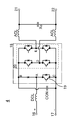
- FIG. FIG. 2 is a circuit diagram of an inverter in the first embodiment.
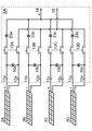
- 6 is a circuit diagram of a current collector in Modification 1.
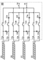
- FIG. 10 is a circuit diagram of a current collector in Modification 2.
- FIG. It is a circuit diagram of the power converter device in Embodiment 2.
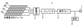
- This AC power supply system 1 includes a current collector 3 (also referred to as a current collector box or a relay terminal box) 3 that bundles the generated power of a plurality of (for example, four) solar cell modules 2A to 2D into one DC power.
- the inverter unit 4 converts the DC power into AC power.
- the AC power output from the inverter unit 4 is appropriately supplied to the load 6 or superimposed on the commercial power supply system 7 via the interconnection relay 5. It has become so.
- Each of the solar cell modules 2A to 2D has a configuration in which a plurality (14 in the drawing) of solar cells are connected in series and a plurality (two in the drawing) are connected in parallel.
- FIG. 2 shows a solar cell module 2A according to the first embodiment, which is an open / close switch 13A (a contact and a contact piece are one circuit, at least two of these circuits are built in, and the contact pieces of the two circuits are linked to each other)
- the solar cell module 2A is connected to the corresponding positive input terminal 11a and negative input terminal 12 provided in the current collector 3, respectively. .
- the positive and negative electrodes of the solar cell module 2A are connected to the positive electrode input terminal 11a and the negative electrode negative input terminal 12a, respectively, and the first diode 10a and the open / close switch 13A are provided.
- the output side of the open / close switch 13A is connected to the positive output terminal 14 and the negative output terminal 15, respectively. That is, the current collector 3 controls the DC power output from the positive electrode output terminal 14 and the negative electrode output terminal 15 by controlling the generated power of the solar cell module 2 ⁇ / b> A with the open / close switch 13 ⁇ / b> A.
- the open / close switch 13A used here has a double-pole single-throw switch for large currents in which the combination of the contact and the intercept is one circuit, and is interposed in the positive and negative lines, respectively.
- An arc extinguishing mechanism that extinguishes arc discharge generated during the opening / closing operation is provided.
- the arc extinguishing mechanism is configured to operate the switch when the positive electrode of the DC power is connected to the positive input terminal of the open / close switch 13A and the negative electrode of the DC power is connected to the negative input terminal of the open / close switch 13A. It is provided to attenuate the arc discharge.
- This arc extinguishing mechanism guides arc discharge in a specific direction from the magnetic material that is specifically arranged in the direction of current flow when the connection is made and the positional relationship between the current and the magnetic material. It is comprised from the arc-extinguishing member arrange
- an open / close switch having such a function for example, there is a DC switch as disclosed in Patent Document 2.
- the 1st diode 10a is connected so that an electric current may flow toward the positive input terminal 11a side from the negative input terminal 12a.
- the outputs of the positive output terminal 14 and the negative output terminal 15 of the current collector 3 are input to the positive input terminal 16 and the negative input terminal 17 of the inverter 4, respectively, as shown in FIG.
- the inverter 4 is mainly a DC / AC conversion circuit, and may be called a power conversion circuit, a PV inverter, a power conditioner, or the like.
- the inverter 4 converts the DC power into a specific AC power of 50 Hz to 60 Hz, that is, an AC power having the same phase as the AC power of the commercial power supply system, and outputs the AC power.
- the direct current power input to the positive input terminal 16 and the negative input terminal 17 of the inverter 4 is input to the switch element module 18 via the direct current reactor DCL.
- the switch element module 18 is configured as an IC as a step-up switching circuit 19 and a single-phase full bridge circuit 20 each having a parallel circuit of a transistor and a free wheel diode.
- the output side of the direct current reactor DCL is connected to the input side A point of the step-up switching circuit 19, and the smoothing capacitor CON is connected between the connection points B and C of the step-up switching circuit 19 and the full bridge circuit 20. Is connected.
- the output points D and E of the full bridge circuit 20 are connected to an AC reactor ACL, respectively.
- the direct current reactor DCL and the alternating current reactor ACL those having a large reactance with respect to a frequency of 50 Hz to 60 Hz are used, and the smoothing capacitor CON having a large capacity is also used.
- the DC reactor DCL, the boosting switching circuit 19 and the smoothing capacitor CON constitute a boost DC / DC converter circuit
- the full bridge circuit 20 and the pair of AC reactor ACLs constitute a DC / AC converter circuit.
- the capacitor Xc connected to the output side of the AC reactor ACL is for noise removal.
- the AC output from the pair of AC reactors ACL is connected to the load 6 and the commercial power supply system 7 (see FIG. 1) via the pair of AC output terminals 21 and 22 and the interconnection relay 5.
- the open / close switch 13A When such an erroneous connection is made, if a circuit for connecting a direct current is formed in the circuit connected to the positive output terminal 14 and the negative output terminal 15, the open / close switch 13A is opened and closed by closing the contact piece. A large current flows through the switch 13A.
- the contact piece of the open / close switch 13A When the contact piece of the open / close switch 13A is opened from the contact in this state, arc discharge occurs between the contact and the contact piece inside the open / close switch 13A. In this arc discharge, since the direction of the current flowing through the open / close switch 13A is opposite to the design direction, the arc discharge direction due to the action of the magnetic material of the arc extinguishing mechanism correctly connected the positive electrode and the negative electrode of the solar cell module 2A.
- the arc extinguishing member did not function in the opposite direction, and as a result, arc discharge continued without being reduced. If arc discharge is continued in the opening / closing switch 13A, the temperature in the opening / closing switch 13A becomes high, and the possibility of failure of the opening / closing switch 13A increases.
- the first diode 10a is connected so that current flows from the negative input terminal 12 of the current collector 3 toward the positive input terminal 11a.
- the reversely connected solar cell module 2A is placed in front of the open / close switch 13A.
- a short circuit occurs via the first diode, and no current flows to the open / close switch 13A. Therefore, the open / close switch 13A does not flow a current that may cause arc discharge when the contact piece of the open / close switch 13A is operated.
- the current collector 3A of Modification 1 shown in FIG. 4 is a case where the solar cell modules are arranged in four rows of solar cell modules 2A to 2D.
- the current collector 3A in the first modification is similar to the current collector 3 of the first embodiment in that the open / close switches 13A to 13D, the positive input terminals 11a to 11d, the negative input terminals 12a to 12d, and the negative input terminals 12a to 12d to the positive electrode.
- the first diodes 10a to 10d connected so that current flows to the input terminals 11a to 11d side, they are provided between the positive output contact side and the positive output terminal 14 of the open / close switches 13A to 13D.
- the second diodes 23a to 23d are inserted in the forward direction, respectively.
- the current collector 3B according to the second modification is configured so that the second diodes 23e to 23h are disposed in the opposite directions between the negative output contact side of the on / off switches 13A to 13D and the negative output terminal 15, respectively. Inserted.
- FIG. 6 shows the power conversion device 24 according to the second embodiment in which the input circuit having the configuration shown in the first modification is used as the input circuit of the inverter unit 4. That is, the power conversion device 24 according to the second embodiment has the positive output terminal 14 and the negative output terminal 15 of the first modification shown in FIG. 4 (the diodes 10a to 10d may be omitted) of the inverter 4 shown in FIG.
- the power conversion device 24 according to the second embodiment has the positive output terminal 14 and the negative output terminal 15 of the first modification shown in FIG. 4 (the diodes 10a to 10d may be omitted) of the inverter 4 shown in FIG.
- an input circuit composed of another open / close throw switch 13E and the first diode 10e is interposed.
- the open / close switch 13E includes an arc extinguishing mechanism that attenuates arc discharge, as in the case of the above-described open / close switches 13A to 13D.
- the first diode 10e is electrically connected so that a current flows from the negative input terminal 12e of the open / close switch 13E to the positive input terminal 11e.
- the positive output terminal 14 of the current collector 3 is mistakenly connected to the negative input terminal 17 as in the case of the input circuit having the configuration shown in Modification 1 described above.
- the negative output terminal 15 is connected to the positive input terminal 16, current is prevented from flowing through the open / close switch 13E.
- the DC power applied to the negative input terminal 17 constitutes a circulation circuit that returns to the positive input terminal 16 via a free wheel diode and a direct current reactor DCL that are provided in addition to the switch element of the switching circuit 19 of the booster, and the open / close switch 13E. However, no current flows through this circuit by the first diode 10e.
Landscapes
- Engineering & Computer Science (AREA)
- Power Engineering (AREA)
- Dc-Dc Converters (AREA)
- Driving Mechanisms And Operating Circuits Of Arc-Extinguishing High-Tension Switches (AREA)
- Keying Circuit Devices (AREA)
- Inverter Devices (AREA)
- Photovoltaic Devices (AREA)
Abstract
Description
前記双極単投スイッチは、前記直流電力の正極が正極入力端子に接続されかつ前記直流電力の負極が負極入力端子に接続されている際に、このスイッチの操作時のアーク放電を減衰させる消弧機構を有すると共に、前記負極入力端子から前記正極入力端子へ向けて電流が流れる方向にダイオードが電気的に接続されていることを特徴とする。
最初に、図1を用いて実施形態1の交流電力供給システム1の概略構成について説明する。この交流電力供給システム1は、複数個(例えば4個)の太陽電池モジュール2A~2Dの発電電力を一つの直流電力に束ねる集電部(集電箱、中継端子箱とも称される)3と、この直流電力を交流電力に変換するインバータ部4とを備えており、インバータ部4から出力される交流電力は、連系リレー5を経て、適宜負荷6に供給ないし商用電源系統7に重畳されるようになっている。
[実施形態2]
図6は、インバータ部4の入力回路として、変形例1に示した構成の入力回路を用いた実施形態2の電力変換装置24を示す。すなわち、実施形態2の電力変換装置24は、図4に示す変形例1(ダイオード10a~10dは削除してもよい。)の正極出力端子14及び負極出力端子15を図3に示すインバータ4の正極入力端子16及び負極入力端子17に接続する際に、別開閉投スイッチ13Eと第1のダイオード10eとからなる入力回路を介在させものである。
2A~2D…太陽電池モジュール
3、3A、3B…集電部(中継端子箱)
4…インバータ
5…連系リレー
6…負荷
7…商用電源系統
10a~10e…第1のダイオード
11a~11e…正極入力端子
12a~12e…負極入力端子
13A~13E…開閉スイッチ
14…正極出力端子
15…負極出力端子
16…正極入力端子
17…負極入力端子
18…スイッチ素子
19…スイッチング回路
20…フルブリッジ回路
21、22…交流出力端子
23a~23h…第2のダイオード
24…電力変換装置
DCL…直流リアクトル
ACL…交流リアクトル
CON…平滑コンデンサ
Xc…コンデンサ
RLY…系統リレー
Claims (5)
- 正極及び負極を有する直流電力を正極入力端子及び負極入力端を有する双極単投スイッチのそれぞれの入力端子に対応させて接続する入力回路おいて、
前記双極単投スイッチは、前記直流電力の正極が正極入力端子に接続されかつ前記直流電力の負極が負極入力端子に接続されている際に、このスイッチの操作時のアーク放電を減衰させる消弧機構を有すると共に、前記負極入力端子から前記正極入力端子へ向けて電流が流れる方向にダイオードが電気的に接続されていることを特徴とする入力回路。 - 前記双極単投スイッチの出力側の端子には、リアクタンス、スイッチング素子、整流ダイオード及びコンデンサを有する昇圧回路が接続され、
前記スイッチング素子には、当該スイッチング素子の動作時の電流方向と逆方向の通電を可能とする還流ダイオードが併設されていることを特徴とする請求項1に記載の入力回路。 - 前記直流電力は、太陽電池で発電されるものであることを特徴とする請求項1又は2に記載の入力回路。
- 直流電力を入力回路を介して入力した後、その電圧を昇圧回路で昇圧し、インバータ回路で交流電力に変換して負荷へ供給する電力変換装置において、
前記入力回路は、前記直流電力の正極及び負極を正極入力端子及び負極入力端を有する双極単投スイッチのそれぞれの入力端子に対応して接続されており、
前記双極単投スイッチは、前記直流電力の正極が前記正極入力端子に接続されかつ前記直流電力の負極が前記負極入力端子に接続されている際に、このスイッチの操作時のアーク放電を減衰させる消弧機構を有すると共に、前記負極入力端子から前記正極入力端子へ向けて電流が流れる方向にダイオードが電気的に接続されており、
前記昇圧回路は、リアクタンス、スイッチング素子、整流ダイオード及びコンデンサを有し、
前記スイッチング素子には、当該スイッチング素子の動作時の電流方向と逆方向の通電を可能とする還流ダイオードが併設されていることを特徴とする電力変換装置。 - 前記直流電力は、太陽電池で発電されるものであることを特徴とする請求項4に記載の電力変換装置。
Priority Applications (3)
| Application Number | Priority Date | Filing Date | Title |
|---|---|---|---|
| JP2014532644A JP5903593B2 (ja) | 2012-08-30 | 2012-08-30 | 入力回路及び電力変換装置 |
| CN201290001291.0U CN204614723U (zh) | 2012-08-30 | 2012-08-30 | 输入电路和电力转换装置 |
| PCT/JP2012/071940 WO2014033868A1 (ja) | 2012-08-30 | 2012-08-30 | 入力回路及び電力変換装置 |
Applications Claiming Priority (1)
| Application Number | Priority Date | Filing Date | Title |
|---|---|---|---|
| PCT/JP2012/071940 WO2014033868A1 (ja) | 2012-08-30 | 2012-08-30 | 入力回路及び電力変換装置 |
Publications (1)
| Publication Number | Publication Date |
|---|---|
| WO2014033868A1 true WO2014033868A1 (ja) | 2014-03-06 |
Family
ID=50182718
Family Applications (1)
| Application Number | Title | Priority Date | Filing Date |
|---|---|---|---|
| PCT/JP2012/071940 Ceased WO2014033868A1 (ja) | 2012-08-30 | 2012-08-30 | 入力回路及び電力変換装置 |
Country Status (3)
| Country | Link |
|---|---|
| JP (1) | JP5903593B2 (ja) |
| CN (1) | CN204614723U (ja) |
| WO (1) | WO2014033868A1 (ja) |
Cited By (4)
| Publication number | Priority date | Publication date | Assignee | Title |
|---|---|---|---|---|
| JPWO2016121402A1 (ja) * | 2015-01-28 | 2017-08-31 | 京セラ株式会社 | 電力制御装置、電力制御システム、および電力制御方法 |
| CN108695963A (zh) * | 2017-03-30 | 2018-10-23 | 本田技研工业株式会社 | 发动机发电机 |
| JP2018170938A (ja) * | 2017-03-30 | 2018-11-01 | パナソニックIpマネジメント株式会社 | 電気機器、電力変換システム、及び端子台 |
| WO2022059976A1 (ko) * | 2020-09-15 | 2022-03-24 | 주식회사 디케이 | 태양광발전용 dc 전원 차단장치 |
Citations (5)
| Publication number | Priority date | Publication date | Assignee | Title |
|---|---|---|---|---|
| JPS63131541U (ja) * | 1987-02-17 | 1988-08-29 | ||
| JPH0945948A (ja) * | 1995-07-27 | 1997-02-14 | Fuji Electric Co Ltd | 太陽電池モジュール |
| JP2000173376A (ja) * | 1998-12-03 | 2000-06-23 | Kawamura Electric Inc | 太陽電池開閉器 |
| JP2002233141A (ja) * | 2001-02-02 | 2002-08-16 | Sharp Corp | 昇圧ユニット |
| JP2012156043A (ja) * | 2011-01-27 | 2012-08-16 | Fuji Electric Co Ltd | 配線用遮断器および直流電力システム |
-
2012
- 2012-08-30 WO PCT/JP2012/071940 patent/WO2014033868A1/ja not_active Ceased
- 2012-08-30 JP JP2014532644A patent/JP5903593B2/ja not_active Expired - Fee Related
- 2012-08-30 CN CN201290001291.0U patent/CN204614723U/zh not_active Expired - Lifetime
Patent Citations (5)
| Publication number | Priority date | Publication date | Assignee | Title |
|---|---|---|---|---|
| JPS63131541U (ja) * | 1987-02-17 | 1988-08-29 | ||
| JPH0945948A (ja) * | 1995-07-27 | 1997-02-14 | Fuji Electric Co Ltd | 太陽電池モジュール |
| JP2000173376A (ja) * | 1998-12-03 | 2000-06-23 | Kawamura Electric Inc | 太陽電池開閉器 |
| JP2002233141A (ja) * | 2001-02-02 | 2002-08-16 | Sharp Corp | 昇圧ユニット |
| JP2012156043A (ja) * | 2011-01-27 | 2012-08-16 | Fuji Electric Co Ltd | 配線用遮断器および直流電力システム |
Cited By (5)
| Publication number | Priority date | Publication date | Assignee | Title |
|---|---|---|---|---|
| JPWO2016121402A1 (ja) * | 2015-01-28 | 2017-08-31 | 京セラ株式会社 | 電力制御装置、電力制御システム、および電力制御方法 |
| US10298018B2 (en) | 2015-01-28 | 2019-05-21 | Kyocera Corporation | Power control apparatus, power control system, and power control method |
| CN108695963A (zh) * | 2017-03-30 | 2018-10-23 | 本田技研工业株式会社 | 发动机发电机 |
| JP2018170938A (ja) * | 2017-03-30 | 2018-11-01 | パナソニックIpマネジメント株式会社 | 電気機器、電力変換システム、及び端子台 |
| WO2022059976A1 (ko) * | 2020-09-15 | 2022-03-24 | 주식회사 디케이 | 태양광발전용 dc 전원 차단장치 |
Also Published As
| Publication number | Publication date |
|---|---|
| CN204614723U (zh) | 2015-09-02 |
| JP5903593B2 (ja) | 2016-04-13 |
| JPWO2014033868A1 (ja) | 2016-08-08 |
Similar Documents
| Publication | Publication Date | Title |
|---|---|---|
| EP4007100B1 (en) | Fault isolation apparatus, direct current boosting apparatus and inversion apparatus | |
| US9438136B2 (en) | Converter for electric power | |
| JP2022523187A5 (ja) | ||
| EP3624333B1 (en) | Shutdown method for photovoltaic module | |
| US11196272B2 (en) | Rapid de-energization of DC conductors with a power source at both ends | |
| CN111226364A (zh) | 电源装置、电力控制装置、电源装置的继电器判定方法 | |
| US20090316323A1 (en) | Circuit arrangement with a relay incorporating one field coil as well as switch contacts | |
| JP6867331B2 (ja) | 全負荷対応型分電盤および全負荷対応型分電盤に対応した蓄電システム | |
| KR20150000493A (ko) | 냉각 부재를 포함하는 에너지 저장 장치, 및 에너지 저장 셀의 냉각 방법 | |
| JP2017135889A (ja) | 電力変換装置、及び電力変換システム | |
| JP6162786B2 (ja) | インバータを用いた系統連系システム | |
| JP5289192B2 (ja) | 電力変換装置および電力変換装置の故障検出方法 | |
| JP5645425B2 (ja) | 電力変換装置 | |
| JP5903593B2 (ja) | 入力回路及び電力変換装置 | |
| JP2011223731A (ja) | 無停電電源システム、および無停電電源システムの制御方法 | |
| JP4932026B1 (ja) | 直流給電システム | |
| JPWO2021005793A1 (ja) | 直流分電盤 | |
| CN114175436A (zh) | 电气网络和用于运行电气网络的方法 | |
| CN120462172A (zh) | 牵引电网和用于运行电动车的牵引电网的方法 | |
| JP6164788B1 (ja) | 車両用電源供給システム、及び車両用電源供給システムの制御方法 | |
| JP5464910B2 (ja) | 電力変換装置 | |
| JP4872322B2 (ja) | マトリクスコンバータ | |
| KR101830380B1 (ko) | 태양발전 전력 스위칭 장치 | |
| JP2014090618A (ja) | パワーコンディショナ装置 | |
| JP5303168B2 (ja) | 小型風力発電系統連系装置 |
Legal Events
| Date | Code | Title | Description |
|---|---|---|---|
| WWE | Wipo information: entry into national phase |
Ref document number: 201290001291.0 Country of ref document: CN |
|
| 121 | Ep: the epo has been informed by wipo that ep was designated in this application |
Ref document number: 12883666 Country of ref document: EP Kind code of ref document: A1 |
|
| ENP | Entry into the national phase |
Ref document number: 2014532644 Country of ref document: JP Kind code of ref document: A |
|
| NENP | Non-entry into the national phase |
Ref country code: DE |
|
| 122 | Ep: pct application non-entry in european phase |
Ref document number: 12883666 Country of ref document: EP Kind code of ref document: A1 |