WO2014032268A1 - 一种训练序列生成方法、训练序列生成装置及光通信系统 - Google Patents
一种训练序列生成方法、训练序列生成装置及光通信系统 Download PDFInfo
- Publication number
- WO2014032268A1 WO2014032268A1 PCT/CN2012/080821 CN2012080821W WO2014032268A1 WO 2014032268 A1 WO2014032268 A1 WO 2014032268A1 CN 2012080821 W CN2012080821 W CN 2012080821W WO 2014032268 A1 WO2014032268 A1 WO 2014032268A1
- Authority
- WO
- WIPO (PCT)
- Prior art keywords
- pseudo
- training
- sequence
- random
- time domain
- Prior art date
Links
Classifications
-
- H—ELECTRICITY
- H04—ELECTRIC COMMUNICATION TECHNIQUE
- H04L—TRANSMISSION OF DIGITAL INFORMATION, e.g. TELEGRAPHIC COMMUNICATION
- H04L27/00—Modulated-carrier systems
- H04L27/26—Systems using multi-frequency codes
- H04L27/2601—Multicarrier modulation systems
- H04L27/2602—Signal structure
- H04L27/261—Details of reference signals
- H04L27/2613—Structure of the reference signals
-
- H—ELECTRICITY
- H04—ELECTRIC COMMUNICATION TECHNIQUE
- H04B—TRANSMISSION
- H04B10/00—Transmission systems employing electromagnetic waves other than radio-waves, e.g. infrared, visible or ultraviolet light, or employing corpuscular radiation, e.g. quantum communication
- H04B10/07—Arrangements for monitoring or testing transmission systems; Arrangements for fault measurement of transmission systems
- H04B10/075—Arrangements for monitoring or testing transmission systems; Arrangements for fault measurement of transmission systems using an in-service signal
- H04B10/077—Arrangements for monitoring or testing transmission systems; Arrangements for fault measurement of transmission systems using an in-service signal using a supervisory or additional signal
- H04B10/0779—Monitoring line transmitter or line receiver equipment
-
- H—ELECTRICITY
- H04—ELECTRIC COMMUNICATION TECHNIQUE
- H04B—TRANSMISSION
- H04B10/00—Transmission systems employing electromagnetic waves other than radio-waves, e.g. infrared, visible or ultraviolet light, or employing corpuscular radiation, e.g. quantum communication
- H04B10/27—Arrangements for networking
-
- H—ELECTRICITY
- H04—ELECTRIC COMMUNICATION TECHNIQUE
- H04B—TRANSMISSION
- H04B10/00—Transmission systems employing electromagnetic waves other than radio-waves, e.g. infrared, visible or ultraviolet light, or employing corpuscular radiation, e.g. quantum communication
- H04B10/50—Transmitters
- H04B10/516—Details of coding or modulation
- H04B10/548—Phase or frequency modulation
-
- H—ELECTRICITY
- H04—ELECTRIC COMMUNICATION TECHNIQUE
- H04B—TRANSMISSION
- H04B10/00—Transmission systems employing electromagnetic waves other than radio-waves, e.g. infrared, visible or ultraviolet light, or employing corpuscular radiation, e.g. quantum communication
- H04B10/50—Transmitters
- H04B10/572—Wavelength control
-
- H—ELECTRICITY
- H04—ELECTRIC COMMUNICATION TECHNIQUE
- H04L—TRANSMISSION OF DIGITAL INFORMATION, e.g. TELEGRAPHIC COMMUNICATION
- H04L27/00—Modulated-carrier systems
- H04L27/26—Systems using multi-frequency codes
- H04L27/2601—Multicarrier modulation systems
- H04L27/2697—Multicarrier modulation systems in combination with other modulation techniques
-
- H—ELECTRICITY
- H04—ELECTRIC COMMUNICATION TECHNIQUE
- H04L—TRANSMISSION OF DIGITAL INFORMATION, e.g. TELEGRAPHIC COMMUNICATION
- H04L7/00—Arrangements for synchronising receiver with transmitter
- H04L7/0075—Arrangements for synchronising receiver with transmitter with photonic or optical means
-
- H—ELECTRICITY
- H04—ELECTRIC COMMUNICATION TECHNIQUE
- H04B—TRANSMISSION
- H04B1/00—Details of transmission systems, not covered by a single one of groups H04B3/00 - H04B13/00; Details of transmission systems not characterised by the medium used for transmission
- H04B1/69—Spread spectrum techniques
- H04B2001/6912—Spread spectrum techniques using chirp
Definitions
- Training sequence generating method Training sequence generating method, training sequence generating device and optical communication system
- the embodiments of the present invention relate to the field of optical communications, and in particular, to a training sequence generating method, a training sequence generating device, and an optical communication system. Background technique
- the metropolitan area and the access optical network system are the hotspots of current research.
- the metropolitan area network integrates and combs the user services distributed in different locations (enterprises, institutions, intelligent communities, commercial and residential buildings, hotels, schools, etc.) to the greatest extent. After the convergence, it is sent to the backbone layer, which makes the network layer very clear and the efficiency is greatly improved.
- the broadband metropolitan area network uses optical fiber as the transmission medium
- the access technology also has various options.
- the mainstream status is: Ethernet access technology and passive optical network (PON, Passive Optical Network) technology.
- PON Passive Optical Network
- IM-DD Intensity Modulation
- DD Direct Detection
- coherent optical communication in contrast to IM-DD, in addition to amplitude modulation of light waves, frequency shift keying or phase shift keying, such as binary phase shift keying , Differential phase shift keying, continuous phase frequency keying, etc., it has a variety of modulation methods, which is conducive to flexible engineering applications, but it increases the complexity and cost of the system.
- IM-DD communication mode is that the system realizes the single order, and the cost of the device is low, which is suitable for the traditional metro and access optical network system.
- OFDM Orthogonal Frequency Division Multiplexing
- IM-DD Orthogonal Frequency Division Multiplexing
- OFDM Orthogonal Frequency Division Multiplexing
- One, the main idea is to divide the channel into several orthogonal subchannels, convert the high-speed data signals into parallel multi-channel low-speed sub-data signals, and modulate each low-speed sub-data signal onto one sub-channel for transmission.
- these low-speed sub-data signals are modulated onto each sub-channel and then orthogonal to each other, and the signal modulated onto each sub-channel is recovered by the demultiplexing technique at the receiving end.
- Figure 1-a shows the frequency domain diagram of OFDM.
- each individual channel has seven subcarriers, each of which is represented by a different peak point and satisfies the entire symbol period.
- Orthogonality that is, the power maximum point of each subcarrier directly corresponds to the power minimum point of the adjacent subcarriers, so that the subcarriers can partially overlap without interfering with each other, and the receiving end can restore the signal without distortion.
- OFDM technology utilizes the spectrum more efficiently by overlapping subcarriers. Although the combination of IM-DD and OFDM technology has the advantages of improved spectral efficiency and no need for dispersion-compensating fiber in the link, distributed feedback laser (DFL, Distributed) is often used in the system due to system cost constraints.
- DFL distributed feedback laser
- the embodiment of the present invention provides a training sequence generating method, a training sequence generating device, and an optical communication system, which are used to solve the frequency offset problem caused by the introduction of the optical signal.
- a first aspect of the present invention provides a training sequence generating method, which is applied to an optical communication system, and includes:
- the pseudo-random sequence is modulated by using the above-mentioned ⁇ coefficient after the inversion to generate a pseudo-random sequence of ⁇ ;
- a training symbol segment including L subcarriers, wherein the L is equal to one half of a number of subcarriers included in one symbol in the optical communication system, where, on the training symbol segment: an even number of subcarriers
- the transmitted signal is a frequency domain signal of a pseudo-random number of the same ordinal number in the pseudo-random sequence of the above-mentioned chirp, and the signal transmitted on the sub-carrier with an odd number of odd-numbered signals is a zero-level signal; Converting the training symbol segment from the frequency domain to the time domain to obtain a training symbol segment in the time domain; generating a training sequence based on the training symbol segment in the time domain, where the time domain structure of the training sequence includes two identical Training symbols, each of the above training symbols consisting of a cyclic prefix and two training symbol segments on the above time domain.
- the foregoing pseudo-random sequence is modulated by using the inverted ⁇ coefficient to generate a pseudo-random sequence of ⁇ , including:
- A(t) the magnitude of the pseudo-random number in the pseudo-random sequence above
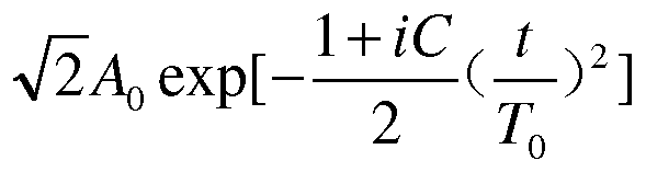
- Modulation generating a pseudo-random sequence of ⁇ , where 0 ⁇ t ⁇ T, the above ⁇ is the period of change of the pseudo-random number, where is the original amplitude of the pseudo-random number, A (0 is the pseudo-random number of the time
- the amplitude after the above amplitude modulation is the imaginary unit in the formula, where C is the above-mentioned ⁇ coefficient after the inverse, where ⁇ is ⁇ (the half width of 0 is equal to 1/e times, where e is natural
- the pseudo-random sequence of the ⁇ is transmitted on the subcarrier with the even number of the training symbol segment, and the zero-level signal is sent on the subcarrier with the odd number of the training symbol segment.
- the method includes: transforming the pseudo-random sequence of the foregoing ⁇ from the time domain to the frequency domain.
- the acquiring the pseudo random sequence is specifically: generating a pseudo random sequence by shifting the shift register.
- the foregoing training symbol segment The transformation from the frequency domain to the time domain is specifically: transforming the above training symbol segments from the frequency domain to the time domain by an inverse fast Fourier transform or an inverse discrete Fourier transform.
- the signal transmitted on the even-numbered subcarrier is a multiple of a frequency domain signal of a pseudo-random number of the same ordinal number in the pseudo-random sequence.
- a second aspect of the present invention provides a training sequence generating apparatus, which is applied to an optical communication system.
- a first generating unit configured to generate a pseudo random sequence, where the number of pseudo random numbers in the pseudo random sequence is equal to one half of the number of subcarriers included in one symbol in the optical communication system;
- An acquiring unit configured to acquire a chirp coefficient of a modulator used in the optical communication system; and a second generating unit, configured to modulate the pseudorandom sequence by using the inverted chirp coefficient to generate a pseudo random of chirp Sequence
- a construction unit configured to construct, in the frequency domain, a training symbol segment including L subcarriers, wherein the L is equal to one half of a number of subcarriers included in one symbol of the optical communication system, where, on the training symbol segment: the ordinal number is
- the signal transmitted on the even subcarriers is a frequency domain signal of a pseudo-random number of the same ordinal number in the pseudo-random sequence of the above-mentioned chirp, and the signal transmitted on the odd-numbered subcarrier is a zero-level signal;
- an inverse Fourier transform unit configured to transform the training symbol from the frequency domain to the time domain to obtain a training symbol segment in the time domain
- a training sequence generating output unit configured to generate a training sequence based on the training symbol segments in the time domain, wherein the time domain structure of the training sequence includes two identical training symbols, each of the training symbols consisting of a cyclic prefix and two The training symbol segments on the above time domain are composed.
- the foregoing second generating unit is specifically configured to use the formula at the time:
- the pseudo-random number is amplitude-modulated to generate a pseudo-random sequence of ⁇ , where 0 ⁇ t ⁇ T, where ⁇ is the period of change of the pseudo-random number, where is the original amplitude of the pseudo-random number, A (0 is the time
- the amplitude of the above pseudo-random number after the amplitude modulation is expressed as an imaginary unit, where C is the inverse of the above-mentioned ⁇ coefficient, where ⁇ is ⁇ (0 is equal to 1/e times the half width, Wherein, e is a natural base;
- the training sequence generating device further includes:
- a Fourier transform unit configured to use the pseudo-random sequence generated by the second generating unit
- the domain is transformed into the frequency domain.
- the foregoing first generating unit is specifically configured to: generate a pseudo random sequence by shifting a shift register .
- the inverse Fourier transform described above The unit is specifically configured to: transform the training symbol segment from a frequency domain to a time domain by an inverse fast Fourier transform or an inverse discrete Fourier transform.
- the foregoing structural unit is further configured to increase a frequency of a signal transmitted on an even-order subcarrier to a frequency domain signal of a pseudo-random number of the same ordinal number in the pseudo-random sequence of the foregoing Double the amplitude.
- a third aspect of the present invention provides an optical communication system, including:
- the training sequence generating device is configured to: generate a pseudo random sequence, where the number of pseudo random numbers in the pseudo random sequence is equal to one half of a number of subcarriers included in one symbol in the optical communication system; and acquiring the optical communication system The ⁇ coefficient of the modulator used in the modulating the pseudo-random sequence by using the inverted ⁇ coefficient to generate a pseudo-random sequence of ⁇ ; constructing a training symbol segment including L subcarriers in the frequency domain, wherein The L is equal to one half of the number of subcarriers included in one symbol of the optical communication system, wherein, on the training symbol segment: the signal transmitted on the even-numbered subcarrier is the same ordinal number in the pseudo-random sequence of the foregoing chirp a frequency domain signal of a pseudo random number, a signal transmitted on an odd numbered subcarrier is a zero level signal; transforming the training symbol segment from a frequency domain to a time domain to obtain a training symbol segment in a time domain; The training symbol segment is generated after the
- the optical transmitter is configured to: insert a training sequence output by the training sequence generating apparatus into a front of a start position of at least one to-be-transmitted symbol, to form a symbol frame carrying a training sequence; and send the foregoing symbol frame by transmitting and processing Giving the above optical receiver;
- the optical receiver is configured to perform symbol timing synchronization processing and carrier frequency synchronization processing by using the training sequence when the symbol frame is received.
- the embodiments of the present invention have the following advantages:
- the ⁇ coefficient and the pseudo random sequence of the optical signal modulator are obtained, and the inverse ⁇ coefficient is used to modulate the pseudo random sequence, and finally the training sequence is generated and output, because the training symbol included in the training sequence
- the signal transmitted on the even-numbered subcarriers of the segment is modulated by using the inverted ⁇ coefficient to generate a pseudo-random sequence. Therefore, when the training sequence passes through the modulator, the positive and negative ⁇ cancel each other, thereby effectively solving the problem.
- the introduction of ⁇ leads to the problem of frequency deviation of optical signals.
- Figure 1-a is a frequency domain diagram of OFDM when no chirp is introduced
- Figure 1-b is a frequency domain diagram of OFDM after the introduction of ⁇ ;
- FIG. 2 is a schematic flowchart of a method for generating a training sequence according to an embodiment of the present invention
- FIG. 2b is a schematic structural diagram of a training symbol in a time domain according to an embodiment of the present invention
- FIG. 3 is a schematic structural diagram of an embodiment of a training sequence generating apparatus according to an embodiment of the present invention
- FIG. 4 is a schematic structural diagram of an optical communication system using a training sequence generated by the present invention according to an embodiment of the present invention
- FIG. 5 is a schematic structural diagram of a single carrier frequency domain equalization system of a training sequence generated by applying the present invention according to an embodiment of the present invention. detailed description
- the embodiment of the invention provides a training sequence generating method, a training sequence generating device and an optical communication system, which can be applied to an optical communication system.
- a training sequence generation method in the embodiment of the present invention is described below. Referring to FIG. 2-a, the method includes:
- the pseudo-random sequence is a series of 0 or 1 in the time domain, for example
- 0010111000011 is a pseudo-random sequence containing 11 pseudo-random numbers.
- the training sequence generating device can generate the pseudo-random sequence through the shift register.
- the training sequence generating device can also use the pseudo-random sequence generator in other manners, which is not limited herein.
- the pseudo random numbers in the pseudo random sequence generated by the training sequence generating device The number is equal to half the number of subcarriers included in one symbol in the optical communication system.
- the training sequence generating means acquires the delay coefficient of the modulator for modulating the transmission signal in the optical communication system.
- the EML has a small coefficient of fall, usually less than or equal to 2
- the DFL has a larger coefficient, usually greater than or equal to 6, due to the transmission bandwidth of the optical communication system and the modulation of the modulator used.
- the coefficient has a certain relationship.
- the relationship between the ⁇ coefficient of EML and the transmission bandwidth of an optical communication system is expressed as follows:
- the training sequence generating device can obtain the ⁇ coefficient of the modulator of the optical communication system according to the relationship between the transmission bandwidth and the ⁇ coefficient of the modulator of the optical communication system.
- the training sequence generating device can also obtain the chirp coefficient of the modulator of the optical communication system by other means.
- the training sequence generating device can obtain the relationship between the bias voltage and the chirp coefficient of the modulator of the optical communication system.
- the chirp coefficient of the modulator of the optical communication system is not limited herein.
- the amplitude modulation is performed to generate a pseudo-random sequence of ⁇ , where 0 ⁇ t ⁇ T, where ⁇ is the period of change of a pseudo-random number, where is the original amplitude of the pseudo-random number for amplitude modulation, A (0 is t
- the L is equal to one half of the number of subcarriers included in one symbol (ie, symbol) in the optical communication system
- the signal transmitted on the even-numbered subcarrier is the pseudo-random of the foregoing
- a signal transmitted on an odd-numbered subcarrier is a zero-level signal. For example, if a subcarrier with an ordinal number of 2, 4, and 6 is included in the training symbol segment, a frequency domain signal of a pseudo random number with a sequence of 2 in a pseudo random sequence of ⁇ is transmitted on a subcarrier with a sequence number of 2.
- a frequency domain signal of a pseudo-random number of 4 in a pseudo-random sequence of a pseudo-random sequence transmitted on a subcarrier of order 4, and a pseudo-random sequence of 6 in a pseudo-random sequence transmitted on a subcarrier of ordinal number 6 The frequency domain signal of the random number.
- the amplitude of the signal transmitted on the sub-carriers having the even-numbered order is increased to be the multiple of the amplitude of the frequency-domain signal of the pseudo-random number of the same ordinal number in the pseudo-random sequence.
- the training sequence generating device first performs a Fourier transform (eg, may be a fast Fourier transform (FFT) , Fast Fourier Transformation ) or Discrete Fourier Transform ( DFT).
- Step 203 is to generate a ⁇ ⁇ ⁇ ⁇ ⁇ ⁇ ⁇ ⁇ ⁇ ⁇ ⁇ ⁇ ⁇ ⁇ ⁇ ⁇ ⁇ ⁇ ⁇ ⁇ ⁇ ⁇ ⁇ ⁇ ⁇ ⁇ ⁇ ⁇ ⁇ ⁇ ⁇ ⁇ ⁇ ⁇ ⁇ ⁇ ⁇ ⁇ ⁇ ⁇ ⁇ ⁇ ⁇ ⁇ ⁇ ⁇ ⁇ ⁇ ⁇ ⁇ signal.
- a Fourier transform eg, may be a fast Fourier transform (FFT) , Fast Fourier Transformation
- DFT Discrete Fourier Transform
- the training sequence generating device may perform an inverse fast Fourier transform (IFFT). Or the Discrete Fourier Transform (IDFT) transforms the training symbol segment obtained in step 204 from the frequency domain to the time domain to obtain a training symbol segment in the time domain.
- IFFT inverse fast Fourier transform
- IDFT Discrete Fourier Transform
- the time domain structure of the generated training sequence includes two identical training symbols, as shown in FIG. 2-b, each training symbol is composed of a cyclic prefix (CP, Cyclic Prefix) and a training symbol segment 1 and The training symbol segment 2 is composed, wherein the training symbol 1 and the training symbol segment 2 are the training symbol segments in the time domain obtained in step 205. As shown in FIG. 2, the training symbol segment 1 and the training symbol segment 2 each include N/2. Subcarriers, where N is the number of subcarriers included in one symbol in the above optical communication system.
- the training sequence generated in the embodiment of the present invention can be applied to optical orthogonal frequency division.
- the (O-OFDM, Optical-Orthogonal Frequency Division Multiplexing) system it can also be applied to a single-carrier frequency-domain equalization system, or to other optical communication systems that are introduced into the ⁇ by a modulator, which is not limited herein. .
- the training sequence generating apparatus 300 in the embodiment of the present invention includes:
- a first generating unit 301 configured to generate a pseudo random sequence
- the pseudo-random sequence is a series of 0 or 1 in the time domain.
- the first generating unit 301 can generate the pseudo-random sequence through the shift register.
- the first generating unit 301 can also be a pseudo-random sequence generator by other means, which is not limited herein.
- the number of pseudo-random numbers in the pseudo-random sequence generated by the first generating unit 301 is equal to half of the number of sub-carriers included in one symbol in the optical communication system.
- the obtaining unit 302 is configured to acquire a chirp coefficient of a modulator used in the optical communication system.
- a second generating unit 303 configured to modulate the pseudo-random sequence generated by the first generating unit 301 by using the inverted ⁇ coefficient to generate a pseudo-random sequence of ⁇ ;
- the second generating unit 303 is specifically configured to:
- the pseudo-random number is amplitude-modulated to generate a training sequence of ⁇ , where 0 ⁇ t ⁇ T, where ⁇ is the period of change of a pseudo-random number, where A is.
- A(0 is the amplitude of the above-mentioned pseudo-random sequence at time t, where is the imaginary unit, where C is the inverse of the chirp coefficient obtained by the acquisition unit 302.
- the enthalpy coefficient obtained after the formula is ⁇ .
- a (0 is equal to 1/e times The half width of the time, where e is the natural base.
- the constructing unit 304 is configured to construct, in the frequency domain, a training symbol segment including L subcarriers, where L is equal to one half of the number of subcarriers included in one symbol in the optical communication system, where, on the training symbol segment: the ordinal number is
- the signal transmitted on the even subcarriers is the frequency domain signal of the pseudo-random number of the same ordinal number in the pseudo-random sequence of the above-mentioned chirp, and the signal transmitted on the odd-numbered subcarriers is a zero-level signal.
- the construction unit 304 expands the amplitude of the signal transmitted on the sub-carriers of the above-order even number to a multiple of the amplitude of the frequency-domain signal of the pseudo-random number of the same ordinal number in the pseudo-random sequence of the above-mentioned chirp.
- the training sequence generating apparatus 300 further includes: a Fourier transform unit (not shown) for Before the construction unit 304 triggers, the pseudo-random sequence generated by the second generation unit 303 is transformed from the time domain to the frequency domain and then output to the construction unit 304.
- the inverse Fourier transform unit 305 is configured to transform the training symbol constructed by the constructing unit 304 from the frequency domain to the time domain to obtain a training symbol segment in the time domain.
- the training sequence generation output unit 306 is configured to generate a training sequence based on the training symbol segments in the time domain transformed by the inverse Fourier transform unit 305, wherein the training sequence generates the time domain structure of the training sequence generated by the output unit 306. Two identical training symbols are included, wherein each training symbol consists of a cyclic prefix and a training symbol segment on the time domain transformed by the two inverse Fourier transform units 305.
- the training sequence generating apparatus 300 in the embodiment of the present invention may be applied to a 0-OFDM system, may also be applied to a single carrier frequency domain equalization system, or may be applied to other types introduced by a modulator.
- the optical communication system it is not limited herein.
- the training sequence generating apparatus 300 in the embodiment of the present invention may be used as the training sequence generating apparatus in the foregoing method embodiment, and may be used to implement all the technical solutions in the foregoing method embodiments, and the functions of the various functional modules may be The method in the foregoing method is specifically implemented. For the specific implementation process, reference may be made to the related description in the foregoing embodiments, and details are not described herein again.
- the training sequence generating apparatus in the embodiment of the present invention obtains the ⁇ coefficient and the pseudo random sequence of the optical signal modulator, modulates the pseudo random sequence by using the inverted ⁇ coefficient, and finally generates a training sequence and outputs the same. Because the signal transmitted on the even-numbered subcarriers of the training symbol segment included in the training sequence is modulated by using the inverted ⁇ coefficient to generate a pseudo-random sequence, therefore, When the training sequence passes through the modulator, the positive and negative ⁇ cancel each other, which effectively solves the problem of frequency deviation of the optical signal caused by the introduction of ⁇ .
- the embodiment of the present invention further provides an optical communication system that applies the training sequence generated by the embodiment of the present invention. As shown in FIG. 4, the optical communication system 400 includes a training sequence generating device 401, an optical transmitter 402, and an optical receiver 403.
- the training sequence generating device 401 in the embodiment of the present invention may be used as the training sequence generating device in the foregoing device embodiment, and may be used to implement all the technical solutions in the foregoing device embodiments, and the functions of the respective functional modules may be according to the foregoing method.
- the method in the embodiment is specifically implemented. For the specific implementation process, refer to the related description in the foregoing embodiment, and details are not described herein again.
- the optical transmitter 402 is configured to insert the training sequence output by the training sequence generating device 401 into the front of the start position of at least one symbol to be transmitted, to form a symbol frame carrying the training sequence;
- the optical transmitter 402 may insert one training sequence in front of the starting position of each symbol to be transmitted, or insert one training sequence every several to-be-transmitted symbols, and the specific insertion manner may be based on The actual needs of the optical communication system are designed and are not limited herein.
- the optical receiver 403 is configured to perform symbol timing synchronization processing and carrier frequency synchronization processing by using the training sequence in the foregoing symbol when receiving the symbol frame from the optical transmitter 402.
- the optical receiving When receiving the above-mentioned symbol frame transmitted by the optical transmitter 402, the machine 403 may perform symbol timing synchronization processing and carrier frequency by using the above-mentioned training sequence in the above symbol, using a symbol timing synchronization method such as Schmidl & Cox (ie S&C) algorithm or sliding window method. Synchronous processing.
- a symbol timing synchronization method such as Schmidl & Cox (ie S&C) algorithm or sliding window method. Synchronous processing.
- a single carrier frequency domain equalization system architecture diagram of a training sequence generated in an embodiment of the present invention is applied.
- a bit data stream is subjected to quadrature amplitude modulation (QAM).
- QAM quadrature amplitude modulation
- the training sequence output by the training sequence generating device in the embodiment of the present invention is added to the OFDM framing module to form a frame format of the OFDM, which is modulated by the modulator onto the optical carrier and transmitted in the optical fiber.
- the optical signal transmitted from the optical fiber is converted into an electrical signal in the photoelectric conversion module, the CP module is removed, the CP in the electrical signal is removed, and symbol timing synchronization processing is performed in the symbol timing synchronization module. Further sampling frequency synchronization processing of the sampling frequency synchronization module and carrier of the carrier frequency synchronization module After the frequency synchronization processing, frequency domain equalization processing is sequentially performed by the FFT module, the frequency equalizer, and the IFFT module, and the frequency-domain equalized processed signal is QAM-demapped to restore the original bit data stream.
- the training sequence generating device 401 in the embodiment of the present invention may be integrated in the optical transmitter 402, or may be a device independent of the optical transmitter 402, which is not limited herein.
- the disclosed apparatus and method can be implemented in other ways.
- the device embodiments described above are merely illustrative.
- the division of the unit is only a logical function division.
- there may be another division manner for example, multiple units or components may be combined or Can be integrated into another system, or some features can be ignored, or not executed.
- the mutual coupling or direct coupling or communication connection shown or discussed may be an indirect coupling or communication connection through some interface, device or unit, and may be electrical, mechanical or otherwise.
- the components displayed by the unit may or may not be physical units, that is, may be located in one place, or may be distributed to multiple network units. Some or all of the units may be selected according to actual needs to achieve the objectives of the solution of the embodiment.
- each functional unit in each embodiment of the present invention may be integrated into one processing unit, or each unit may exist physically separately, or two or more units may be integrated into one unit.
- the above integrated unit can be implemented in the form of hardware or in the form of a software functional unit.
- the integrated unit if implemented in the form of a software functional unit and sold or used as a standalone product, may be stored in a computer readable storage medium.
- the technical solution of the present invention may contribute to the prior art or all or part of the technical solution may be embodied in the form of a software product stored in a storage medium.
- a number of instructions are included to cause a computer device (which may be a personal computer, server, or network device, etc.) to perform all or part of the steps of the methods described in various embodiments of the present invention.
- the foregoing storage medium includes: a U disk, a removable hard disk, a read-only memory (ROM), a random access memory (RAM), a magnetic disk or an optical disk, and the like, which can store program codes. .
Landscapes
- Engineering & Computer Science (AREA)
- Computer Networks & Wireless Communication (AREA)
- Signal Processing (AREA)
- Physics & Mathematics (AREA)
- Electromagnetism (AREA)
- Computing Systems (AREA)
- Optics & Photonics (AREA)
- Optical Communication System (AREA)
Abstract
本发明实施例提供了一种训练序列生成方法、训练序列生成装置及光通信系统,其中,一种训练序列生成方法包括:生成伪随机序列;获取光通信系统中使用的调制器的啁啾系数;利用取反后的啁啾系数对伪随机序列进行调制,生成啁啾的伪随机序列;在频域上构造包含L个子载波的训练符号段,其中,在该训练符号段上:序数为偶数的子载波上发送的信号为啁啾的伪随机序列中相同序数的伪随机数的频域信号,序数为奇数的子载波上发送的信号为零电平信号;将训练符号段从频域变换到时域,得到时域上的训练符号段;基于时域上的训练符号段生成训练序列后输出。本发明提供的技术方案能够有效解决啁啾的引入导致的光信号频偏问题。
Description
一种训练序列生成方法、 训练序列生成装置及光通信系统 技术领域
本发明实施例涉及光通信领域, 尤其涉及一种训练序列生成方法、训练序 列生成装置及光通信系统。 背景技术
城域与接入光网络系统是目前研究的热点, 城域网是将分布在不同地点 (企业、 机关、 智能小区、 商住楼、 宾馆、 学校等)的用户业务进行最大程度 的整合、 梳理、 汇聚后, 再送往骨干层, 从而使网络层次变得非常清晰, 效率 也得到极大提升。宽带城域网以光纤作为传输媒介时,接入技术也有多种选择, 目前居于主流地位的有: 以太网接入技术和无源光网络( PON , Passive Optical Network )技术。 从整体上来讲, 城域与接入光网络系统具有系统筒单, 成本 低廉的特点。 从七十年代开始, 损耗为 20dB的光纤问世后, 人们最先研制并 使用的是强度调制( IM, Intensity Modulation ) -直接检测( DD, Direct Detection ) 方式的光纤通信, 这种方式具有筒单、 经济、 易于调整等优点。 此外还存在另 外一种光纤通信: 相干光通信, 相对于 IM-DD, 相干光通信除了可以对光波进 行幅度调制外, 还可以进行频移键控或相移键控, 如二进制相移键控、 差分相 移键控、 连续相频键控等, 其具有多种调制方式, 利于灵活的工程应用, 但是 它增加了系统的复杂性和成本。 与相干光通信比较, IM-DD通信方式主要优点 是系统实现筒单, 并且器件所需要的成本较低,适合应用于传统的城域与接入 光网络系统。
在高速传输系统中, 采用 IM-DD和正交频分复用 (OFDM , Orthogonal Frequency Division Multiplexing )技术相结合的方案, OFDM技术是一种特殊 的频分复用技术, OFDM是多载波调制的一种, 其主要思想是将信道划分为若 干个正交子信道, 将高速数据信号转换成并行的多路低速子数据信号, 将每路 低速子数据信号调制到一个子信道上进行传输,在频域上, 这些低速子数据信 号调制到每个子信道上后彼此正交,在接收端通过解复用技术来恢复被调制到 每个子信道上的信号。 如图 1-a为 OFDM的频域图, 在图 1-a中, 每个单独的信 道有七个子载波,每个子载波都由不同的峰值点表示且在整个符号周期内满足
正交性, 即每个子载波的功率最大值点直接对应于相邻子载波的功率最小值 点,从而使这些子载波能够部分重叠而不互相干扰,保证接收端能够不失真地 复原信号。 OFDM技术通过使子载波重叠而更有效地利用了频谱。 虽然采用 IM-DD和 OFDM技术相结合的方案具有提高频谱效率,且在链路中不需要色散 补偿光纤等优点, 但是, 由于系统成本的限制, 该系统中常采用分布式反馈激 光器( DFL, Distributed Feedback Laser ) ,直接调制 ( DFB , Distributed Feedback Bragg )激光器或电吸收调制器集成激光器( EML, Electro-Absorption Modulator Integrated with laser )作为光信号调制器, 而这些光信号调制器在进行幅度调 制的同时不可避免的伴随有相位调制, 输出的光信号伴有随时间变化的相移, 这种现象称为啁啾, 啁啾的光信号经过标准单模光纤后, 在接收端对信号的影 响导致光信号的频偏, 啁啾越大, 频偏越大; 不同频率的光信号, 频偏不同。 图 1-b为接收端在啁啾的引入后 OFDM的频域图, 由图 1-b可见, 由于啁啾的引 入,使得光信号在接收端的正交特性被破坏, 即每个子载波的功率最大值点不 再直接对应于相邻子载波的功率最小值点,从而导致了严重的符号间串扰。 目 前并没有相关技术方案能够有效解决啁啾引入导致的光信号频偏问题。 发明内容
本发明实施例提供了一种训练序列生成方法、训练序列生成装置及光通信 系统, 用于解决啁啾引入导致的光信号频偏问题。
本发明第一方面提供了一种训练序列生成方法, 应用于光通信系统中, 包括:
生成伪随机序列, 其中, 上述伪随机序列中的伪随机数的个数等于上述光 通信系统中一个符号包含的子载波数的一半;
获取上述光通信系统中使用的调制器的啁啾系数;
利用取反后的上述啁啾系数对上述伪随机序列进行调制,生成啁啾的伪随 机序列;
在频域上构造包含 L个子载波的训练符号段, 其中, 上述 L等于上述光 通信系统中一个符号包含的子载波数的一半, 其中, 在上述训练符号段上: 序 数为偶数的子载波上发送的信号为上述啁啾的伪随机序列中相同序数的伪随 机数的频域信号, 序数为奇数的子载波上发送的信号为零电平信号;
将上述训练符号段从频域变换到时域, 得到时域上的训练符号段; 基于上述时域上的训练符号段生成训练序列后输出, 其中, 上述训练序列 的时域结构包含两个相同的训练符号,每个上述训练符号由循环前缀和两个上 述时域上的训练符号段组成。
结合本发明的第一方面, 在第一种可能的实现方式中, 上述利用取反后的 上述啁啾系数对上述伪随机序列进行调制, 生成啁啾的伪随机序列, 包括: 在时
A(t) = , 对上述伪随机序列中的伪随机数进行幅度
调制, 生成啁啾的伪随机序列, 其中, 0≤t≤T , 上述 Γ为上述伪随机数的变化 周期, 式中 为上述伪随机数的原始幅度, A(0为 时刻上述伪随机数经上述 幅度调制后的幅度, 式中 为虚数单位, 式中 C为取反后的上述啁啾系数, 式 中 Γ。为当 Α(0等于 1/e倍 时的半幅宽度, 其中, e为自然底数; 上述在频域上,在上述训练符号段的序数为偶数的子载波上发送上述啁啾 的伪随机序列, 在上述训练符号段的序数为奇数的子载波上发送零电平信号, 之前包括: 将上述啁啾的伪随机序列从时域变换到频域。
结合本发明第一方面或者本发明第一方面的第一种可能实现方式,在第二 种可能的实现方式中, 上述获取伪随机序列具体为: 通过移位寄存器移位生成 伪随机序列。
结合本发明第一方面,或者本发明第一方面的第一种可能实现方式,或者 本发明第一方面的第二种可能实现方式,在第三种可能实现方式中, 上述将上 述训练符号段从频域变换到时域具体为:通过快速傅里叶逆变换或者离散傅里 叶逆变换将上述训练符号段从频域变换到时域。
结合本发明第一方面,或者本发明第一方面的第一种可能实现方式,或者 本发明第一方面的第二种可能实现方式,或者本发明第一方面的第三种可能实 现方式,在本发明第四种可能实现方式中, 上述序数为偶数的子载波上发送的 信号为上述啁啾的伪随机序列中相同序数的伪随机数的频域信号的 Ϊ倍。
本发明第二方面提供了一种训练序列生成装置, 应用于光通信系统中,
包括:
第一生成单元, 用于生成伪随机序列, 其中, 上述伪随机序列中的伪随机 数的个数等于上述光通信系统中一个符号包含的子载波数的一半;
获取单元, 用于获取上述光通信系统中使用的调制器的啁啾系数; 第二生成单元,用于利用取反后的上述啁啾系数对上述伪随机序列进行调 制, 生成啁啾的伪随机序列;
构造单元, 用于在频域上构造包含 L个子载波的训练符号段, 其中, 上述 L等于上述光通信系统中一个符号包含的子载波数的一半, 其中, 在上述训练 符号段上:序数为偶数的子载波上发送的信号为上述啁啾的伪随机序列中相同 序数的伪随机数的频域信号, 序数为奇数的子载波上发送的信号为零电平信 号;
傅里叶逆变换单元, 用于将上述训练符号从频域变换到时域,得到时域上 的训练符号段;
训练序列生成输出单元,用于基于上述时域上的训练符号段生成训练序列 后输出, 其中, 上述训练序列的时域结构包含两个相同的训练符号, 每个上述 训练符号由循环前缀和两个上述时域上的训练符号段组成。
结合本发明第二方面,在第一种可能实现方式中, 上述第二生成单元具体 用于在时 利用公式:
A( = , 对上述第一生成单元生成的伪随机序列的

伪随机数进行幅度调制, 生成啁啾的伪随机序列, 其中, 0≤t≤T , 上述 Γ为上 述伪随机数的变化周期, 式中 为上述伪随机数的原始幅度, A(0为 时刻上 述伪随机数经上述幅度调制后的幅度, 式中 为虚数单位, 式中 C为取反后的 上述啁啾系数, 式中 Γ。为当 Α(0等于 1/e倍 时的半幅宽度, 其中, e为自然 底数; 上述训练序列生成装置还包括:
傅里叶变换单元,用于将上述第二生成单元生成的啁啾的伪随机序列从时
域变换到频域。
结合本发明第二方面,或者本发明第二方面的第一种可能实现方式中, 在 第二种可能实现方式中, 上述第一生成单元具体用于: 通过移位寄存器移位生 成伪随机序列。
结合本发明第二方面,或者本发明第二方面的第一种可能实现方式,或者 本发明第二方面的第二种可能实现方式,在第三种可能实现方式中, 上述傅里 叶逆变换单元具体用于:通过快速傅里叶逆变换或者离散傅里叶逆变换将上述 训练符号段从频域变换到时域。
结合本发明第二方面,或者本发明第二方面的第一种可能实现方式,或者 本发明第二方面的第二种可能实现方式,或者本发明第二方面的第三种可能实 现方式,在第四种可能实现方式中, 上述构造单元还用于将在序数为偶数的子 载波上发送的信号的幅度增大为上述啁啾的伪随机序列中相同序数的伪随机 数的频域信号的幅度的 ϊ倍。
本发明第三方面提供了一种光通信系统, 包括:
训练序列生成装置, 光发射机和光接收机;
其中, 上述训练序列生成装置用于: 生成伪随机序列, 其中, 上述伪随机 序列中的伪随机数的个数等于上述光通信系统中一个符号包含的子载波数的 一半; 获取上述光通信系统中使用的调制器的啁啾系数; 利用取反后的上述啁 啾系数对上述伪随机序列进行调制, 生成啁啾的伪随机序列; 在频域上构造包 含 L个子载波的训练符号段, 其中, 上述 L等于上述光通信系统中一个符号 包含的子载波数的一半, 其中, 在上述训练符号段上: 序数为偶数的子载波上 发送的信号为上述啁啾的伪随机序列中相同序数的伪随机数的频域信号,序数 为奇数的子载波上发送的信号为零电平信号;将上述训练符号段从频域变换到 时域,得到时域上的训练符号段; 基于上述时域上的训练符号段生成训练序列 后输出, 其中, 上述训练序列的时域结构包含两个相同的训练符号, 每个上述 训练符号由循环前缀和两个上述时域上的训练符号段组成;
其中, 上述光发射机用于: 将上述训练序列生成装置输出的训练序列插入 到至少一个待发送符号的起始位置的前面, 形成携带训练序列的符号帧; 将上 述符号帧经发射处理后发送给上述光接收机;
其中, 上述光接收机用于在接收到上述符号帧时, 利用上述训练序列进行 符号定时同步处理和载波频率同步处理。
从以上技术方案可以看出, 本发明实施例具有以下优点:
本发明实施例中通过获取光信号调制器的啁啾系数和伪随机序列,使用取 反后的啁啾系数对伪随机序列进行调制, 最终生成训练序列并输出, 由于该训 练序列包含的训练符号段的序数为偶数的子载波上发送的信号是使用取反后 的啁啾系数对伪随机序列进行调制生成, 因此, 当训练序列经过调制器后, 正 负啁啾相抵消, 从而有效解决了啁啾的引入导致的光信号频偏问题。 附图说明
图 1-a为未引入啁啾时的 OFDM的频域图;
图 1-b为在啁啾的引入后的 OFDM的频域图;
图 2-a为本发明实施例提供的训练序列生成方法一个实施例流程示意图; 图 2-b为本发明实施例中的训练符号在时域上的结构示意图;
图 3为本发明实施例提供的训练序列生成装置一个实施例结构示意图; 图 4 为本发明实施例提供的应用本发明生成的训练序列的光通信系统结 构示意图;
图 5 为本发明实施例提供的应用本发明生成的训练序列的单载波频域均 衡系统结构示意图。 具体实施方式
本发明实施例提供了一种训练序列生成方法、训练序列生成装置及光通信 系统, 可以应用于光通信系统中。
下面对本发明实施例中的一种训练序列生成方法进行描述,请参阅图 2-a, 包括:
201、 生成伪随机序列;
在本发明实施例中, 伪随机序列在时域上看是一系列的 0 或 1 , 例如
0010111000011为包含 11个伪随机数的伪随机序列。训练序列生成装置可以通 过移位寄存器生成该伪随机序列, 当然,训练序列生成装置也可以通过其它方 式伪随机序列发生器, 此处不作限定。
本发明实施例中,训练序列生成装置生成的伪随机序列中的伪随机数的个
数等于光通信系统中一个符号包含的子载波数的一半。
202、 获取光通信系统中使用的调制器的啁啾系数;
训练序列生成装置获取光通信系统中用于对传输信号进行调制的调制器 的啁秋系数。
在实际应用中, EML的啁秋系数较小, 通常小于或等于 2, 而 DFL的啁 啾系数较大, 通常大于或者等于 6 , 由于光通信系统的传输带宽与其所使用的 调制器的啁啾系数有一定的关系。 例如, EML 的啁啾系数与光通信系统的传 输带宽的关系如下式表示:
/ = tan— —:― 1 /Γ^ , 其中, 式中 是啁啾系数, β2为色散系数, L
2π p2L 为光纤长度。
因此, 本发明实施例中,训练序列生成装置可以才艮据传输带宽与光通信系 统的调制器的啁啾系数的关系, 获取光通信系统的调制器的啁啾系数, 当然, 本发明实施例中的训练序列生成装置也可以通过其它方式来获取光通信系统 的调制器的啁啾系数, 例如,训练序列生成装置可以根据光通信系统的调制器 的偏置电压与啁啾系数的关系来获取光通信系统的调制器的啁啾系数,此处不 作限定。
203、 利用取反后的啁啾系数对上述伪随机序列进行调制, 生成啁啾的伪 随机序列;
在本发明一 练序列生成装置在时域上利用公式: A(t) = f2A0 ] , 对步骤 201获取的伪随机序列中的伪随机
 数进行幅度调制, 生成啁啾的伪随机序列, 其中, 0≤t≤T , Γ为一个伪随机数 的变化周期, 式中 为进行幅度调制的伪随机数的原始幅度, A(0为 t时刻上 述啁啾的伪随机序列的幅度, 式中 为虚数单位, 式中 C为对步骤 202获取的 啁啾系数进行取反得到的啁啾系数, 式中 Γ。为当 A(0等于 1^倍 时的半幅宽 度, 其中, e为自然底数。
204、 在频域上构造包含 L个子载波的训练符号段;
数进行幅度调制, 生成啁啾的伪随机序列, 其中, 0≤t≤T , Γ为一个伪随机数 的变化周期, 式中 为进行幅度调制的伪随机数的原始幅度, A(0为 t时刻上 述啁啾的伪随机序列的幅度, 式中 为虚数单位, 式中 C为对步骤 202获取的 啁啾系数进行取反得到的啁啾系数, 式中 Γ。为当 A(0等于 1^倍 时的半幅宽 度, 其中, e为自然底数。
204、 在频域上构造包含 L个子载波的训练符号段;
其中, 上述 L等于上述光通信系统中一个符号 (即 symbol ) 包含的子载 波数的一半, 且, 在上述训练符号段上: 序数为偶数的子载波上发送的信号为 上述啁啾的伪随机序列中相同序数的伪随机数的频域信号,序数为奇数的子载 波上发送的信号为零电平信号。举例说明,假设在上述训练符号段上包含序数 为 2、 4、 6的子载波, 则在序数为 2的子载波上发送啁啾的伪随机序列中序数 为 2的伪随机数的频域信号,在序数为 4的子载波上发送啁啾的伪随机序列中 序数为 4的伪随机数的频域信号,在序数为 6的子载波上发送啁啾的伪随机序 列中序数为 6的伪随机数的频域信号。
进一步, 为了保证符号的发射功率,将上述序数为偶数的子载波上发送的 信号的幅度增大为上述啁啾的伪随机序列中相同序数的伪随机数的频域信号 的幅度的 倍。
在本发明实施例中, 若步骤 203生成的啁啾的伪随机序列为时域信号, 则 在步骤 204之前,训练序列生成装置先通过傅里叶变换(如可以是快速傅里叶 变换 ( FFT, Fast Fourier Transformation )或离散傅里叶变换 ( DFT, Discrete Fourier Transform) ) 寻步骤 203生成々ρ周大々伪随机序歹l从时域更换 频域, 得到啁啾的伪随机序列的频域信号。 以便在步骤 204中构造上述训练符号段。
205、 将上述训练符号段从频域变换到时域, 得到时域上的训练符号段; 在本发明实施例中,训练序列生成装置可以通过快速傅里叶逆变换( IFFT, Inverse Fast Fourier Transformation )或者离散傅里叶逆更换 ( IDFT, Inverse Discrete Fourier Transform )将步骤 204得到的训练符号段从频域变换到时域, 得到时域上的训练符号段。
206、 基于上述时域上的训练符号段生成训练序列后输出;
在本发明实施例中, 生成的训练序列的时域结构包含两个相同的训练符 号, 如图 2-b所示, 每个训练符号由循环前缀(CP, Cyclic Prefix )和训练符 号段 1和训练符号段 2组成, 其中, 训练符号 1和训练符号段 2均为步骤 205 得到的时域上的训练符号段,如图 2所示,训练符号段 1和训练符号段 2各包 含 N/2个子载波, 其中, N为上述光通信系统中一个符号包含的子载波数。
需要说明的是,本发明实施例中生成的训练序列可以应用于光正交频分复
用 ( O-OFDM , Optical-Orthogonal Frequency Division Multiplexing ) 系统中 , 也可以应用于单载波频域均衡系统中, 或者,应用于其它因调制器而引入啁啾 的光通信系统中, 此处不作限定。
由上可见,本发明实施例中通过获取光信号调制器的啁啾系数和伪随机序 列,使用取反后的啁啾系数对伪随机序列进行调制,最终生成训练序列并输出, 由于该训练序列包含的训练符号段的序数为偶数的子载波上发送的信号是使 用取反后的啁啾系数对伪随机序列进行调制生成, 因此, 当训练序列经过调制 器后, 正负啁啾相抵消, 从而有效解决了啁啾的引入导致的光信号频偏问题。 下面对本发明实施例提供的一种训练序列生成装置进行描述, 请参阅图 3 , 本发明实施例中的训练序列生成装置 300 , 包括:
第一生成单元 301 , 用于生成伪随机序列;
在本发明实施例中, 伪随机序列在时域上看是一系列的 0或 1。 第一生成 单元 301 可以通过移位寄存器生成该伪随机序列, 当然, 第一生成单元 301 也可以通过其它方式伪随机序列发生器, 此处不作限定。
本发明实施例中,第一生成单元 301生成的伪随机序列中的伪随机数的个 数等于光通信系统中一个符号包含的子载波数的一半。
获取单元 302 , 用于获取光通信系统中使用的调制器的啁啾系数。
第二生成单元 303 , 用于利用取反后的啁啾系数对第一生成单元 301生成 的伪随机序列进行调制, 生成啁啾的伪随机序列;
在本发明一种应用场景中, 第二生成单元 303具体用于:
在时域上利 公式:
A(t) = f2A0 ] , 对第一生成单元 301生成的的伪随机序列
 中的伪随机数进行幅度调制, 生成啁啾的训练序列, 其中, 0≤t≤T , Γ为一个 伪随机数的变化周期, 式中 A。为进行幅度调制的伪随机数的原始幅度, A(0为 t时刻上述啁啾的伪随机序列的幅度, 式中 为虚数单位, 式中 C为对获取单元 302获取的啁啾系数进行取反后得到的啁啾系数,式中 Γ。为当 A(0等于 1/e倍
时的半幅宽度, 其中, e为自然底数。
中的伪随机数进行幅度调制, 生成啁啾的训练序列, 其中, 0≤t≤T , Γ为一个 伪随机数的变化周期, 式中 A。为进行幅度调制的伪随机数的原始幅度, A(0为 t时刻上述啁啾的伪随机序列的幅度, 式中 为虚数单位, 式中 C为对获取单元 302获取的啁啾系数进行取反后得到的啁啾系数,式中 Γ。为当 A(0等于 1/e倍
时的半幅宽度, 其中, e为自然底数。
构造单元 304, 用于在频域上构造包含 L个子载波的训练符号段, 其中, L等于上述光通信系统中一个符号包含的子载波数的一半, 其中, 在上述训练 符号段上:序数为偶数的子载波上发送的信号为上述啁啾的伪随机序列中相同 序数的伪随机数的频域信号, 序数为奇数的子载波上发送的信号为零电平信 号。 进一步, 为了保证发射功率, 构造单元 304将在上述序数为偶数的子载波 上发送的信号的幅度扩大为上述啁啾的伪随机序列中相同序数的伪随机数的 频域信号的幅度的 倍。
在本发明实施例中, 若构造单元 304 生成的啁啾的伪随机序列为时域信 号, 则训练序列生成装置 300进一步还包括: 傅里叶变换单元(图中未示出), 用于在构造单元 304触发之前,将第二生成单元 303生成的啁啾的伪随机序列 从时域变换到频域之后输出给构造单元 304。
傅里叶逆变换单元 305 , 用于将构造单元 304构造的上述训练符号从频域 变换到时域, 得到时域上的训练符号段。
训练序列生成输出单元 306, 用于基于傅里叶逆变换单元 305变换后的时 域上的训练符号段, 生成训练序列后输出, 其中, 训练序列生成输出单元 306 生成的训练序列的时域结构包含两个相同的训练符号, 其中,每个训练符号由 循环前缀和两个傅里叶逆变换单元 305变换后的时域上的训练符号段组成。
需要说明的是, 本发明实施例中的训练序列生成装置 300 可以应用于 0-OFDM 系统中, 也可以应用于单载波频域均衡系统中, 或者, 应用于其它 因调制器而引入啁啾的光通信系统中, 此处不作限定。
需要说明的是,本发明实施例中的训练序列生成装置 300可以如上述方法 实施例中的训练序列生成装置,可以用于实现上述方法实施例中的全部技术方 案, 其各个功能模块的功能可以根据上述方法实施例中的方法具体实现, 其具 体实现过程可参照上述实施例中的相关描述, 此处不再赘述。
由上可见,本发明实施例中的训练序列生成装置通过获取光信号调制器的 啁啾系数和伪随机序列,使用取反后的啁啾系数对伪随机序列进行调制, 最终 生成训练序列并输出,由于该训练序列包含的训练符号段的序数为偶数的子载 波上发送的信号是使用取反后的啁啾系数对伪随机序列进行调制生成, 因此,
当训练序列经过调制器后,正负啁啾相抵消,从而有效解决了啁啾的引入导致 的光信号频偏问题。 本发明实施例还提供了一种应用本发明实施例生成的训练序列的光通信 系统,如图 4所示,光通信系统 400包括训练序列生成装置 401 ,光发射机 402 和光接收机 403;
其中,本发明实施例中的训练序列生成装置 401可以如上述装置实施例中 的训练序列生成装置, 可以用于实现上述装置实施例中的全部技术方案, 其各 个功能模块的功能可以根据上述方法实施例中的方法具体实现,其具体实现过 程可参照上述实施例中的相关描述, 此处不再赘述。
其中,光发射机 402用于将训练序列生成装置 401输出的训练序列插入到 至少一个待发送符号的起始位置的前面, 形成携带训练序列的符号帧; 将该符 号帧经发射处理后发送给上述光接收机 403。 本发明实施例中, 光发射机 402 可以在每个待发送符号的起始位置前面都插入一个上述训练序列,也可以每隔 若干个待发送符号插入一个上述训练序列 ,具体地插入方式可以依据光通信系 统的实际需求进行设计, 此处不作限定。
其中,光接收机 403用于在接收到来自光发射机 402发射的上述符号帧时, 利用上述符号中的上述训练序列进行符号定时同步处理和载波频率同步处理; 本发明实施例中,光接收机 403在接收到光发射机 402发射的上述符号帧 时, 可以利用上述符号中的上述训练序列, 采用 Schmidl&Cox (即 S&C )算 法或滑动窗口法等符号定时同步方法进行符号定时同步处理和载波频率同步 处理。
举例说明,如图 5所示为应用本发明实施例中生成的训练序列的单载波频 域均衡系统架构图, 由图 5可见, 在光发射机中, 比特数据流经过正交幅度调 制( QAM, Quadrature Amplitude Modulation )模块的 QAM映射后, 在 OFDM 成帧模块里加入本发明实施例中训练序列生成装置输出的训练序列, 构成 OFDM 的帧格式, 被调制器调制到光载波上在光纤中传输; 在光接收机中, 从光纤中传输过来的光信号在光电转换模块中被转换成电信号, 去 CP模块然 后去除电信号中的 CP, 并在符号定时同步模块里进行符号定时同步处理, 进 一步经过采样频率同步模块的采样频率同步处理和载波频率同步模块的载波
频率同步处理之后, 依次通过 FFT模块、 频率均衡器和 IFFT模块进行频域均 衡处理, 对频域均衡处理后的信号进行 QAM解映射, 还原出原始的比特数据 流。
需要说明的是,本发明实施例中的训练序列生成装置 401可以集成在光发 射机 402中, 也可以是独立于光发射机 402的装置, 此处不作限定。
在本申请所提供的几个实施例中, 应该理解到, 所揭露的装置和方法, 可 以通过其它的方式实现。 例如, 以上所描述的装置实施例仅仅是示意性的, 例 如, 所述单元的划分, 仅仅为一种逻辑功能划分, 实际实现时可以有另外的划 分方式, 例如多个单元或组件可以结合或者可以集成到另一个系统,或一些特 征可以忽略, 或不执行。 另一点, 所显示或讨论的相互之间的耦合或直接耦合 或通信连接可以是通过一些接口, 装置或单元的间接耦合或通信连接, 可以是 电性, 机械或其它的形式。 单元显示的部件可以是或者也可以不是物理单元, 即可以位于一个地方, 或者 也可以分布到多个网络单元上。可以根据实际的需要选择其中的部分或者全部 单元来实现本实施例方案的目的。
另外, 在本发明各个实施例中的各功能单元可以集成在一个处理单元中, 也可以是各个单元单独物理存在,也可以两个或两个以上单元集成在一个单元 中。上述集成的单元既可以采用硬件的形式实现, 也可以采用软件功能单元的 形式实现。
所述集成的单元如果以软件功能单元的形式实现并作为独立的产品销售 或使用时, 可以存储在一个计算机可读取存储介质中。 基于这样的理解, 本发 明的技术方案本质上或者说对现有技术做出贡献的部分或者该技术方案的全 部或部分可以以软件产品的形式体现出来,该计算机软件产品存储在一个存储 介质中, 包括若干指令用以使得一台计算机设备(可以是个人计算机,服务器, 或者网络设备等 )执行本发明各个实施例所述方法的全部或部分步骤。 而前述 的存储介质包括: U盘、 移动硬盘、 只读存储器(ROM, Read-Only Memory )、 随机存取存储器(RAM, Random Access Memory ), 磁碟或者光盘等各种可以 存储程序代码的介质。
以上对本发明所提供的一种训练序列生成方法、训练序列生成装置及光通 信系统进行了详细介绍,对于本领域的一般技术人员,依据本发明实施例的思 想, 在具体实施方式及应用范围上均会有改变之处, 综上, 本说明书内容不应 理解为对本发明的限制。
Claims
1、 一种训练序列生成方法, 应用于光通信系统中, 其特征在于, 包括: 生成伪随机序列, 其中, 所述伪随机序列中的伪随机数的个数等于所述光 通信系统中一个符号包含的子载波数的一半;
获取所述光通信系统中使用的调制器的啁啾系数;
利用取反后的所述啁啾系数对所述伪随机序列进行调制,生成啁啾的伪随 机序列;
在频域上构造包含 L个子载波的训练符号段, 其中, 所述 L等于所述光 通信系统中一个符号包含的子载波数的一半, 其中, 在所述训练符号段上: 序 数为偶数的子载波上发送的信号为所述啁啾的伪随机序列中相同序数的伪随 机数的频域信号, 序数为奇数的子载波上发送的信号为零电平信号;
将所述训练符号段从频域变换到时域, 得到时域上的训练符号段; 基于所述时域上的训练符号段生成训练序列后输出, 其中, 所述训练序列 的时域结构包含两个相同的训练符号,每个所述训练符号由循环前缀和两个所 述时域上的训练符号段组成。
2、 根据权利要求 1所述的方法, 其特征在于, 所述利用取反后的所述啁 啾系数对所述伪随机序列进行调制, 生成啁啾的伪随机序列, 包括:
在时域上, 公式:
A(t) = 2Ao ], 对所述伪随机序列中的伪随机数进行幅度
 调制, 生成啁啾的伪随机序列, 其中, 0≤t≤T , 所述 Γ为所述伪随机数的变化 周期, 式中 为所述伪随机数的原始幅度, A(0为 时刻所述伪随机数经所述 幅度调制后的幅度, 式中 为虚数单位, 式中 C为取反后的所述啁啾系数, 式 中 Γ。为当 Α(0等于 1/e倍 时的半幅宽度, 其中, e为自然底数; 所述在频域上,在所述训练符号段的序数为偶数的子载波上发送所述啁啾 的伪随机序列, 在所述训练符号段的序数为奇数的子载波上发送零电平信号, 之前包括:
将所述啁啾的伪随机序列从时域变换到频域。
3、 根据权利要求 1或 2所述的方法, 其特征在于,
所述获取伪随机序列具体为:
通过移位寄存器移位生成伪随机序列。
4、 根据权利要求 1至 3任一项所述的方法, 其特征在于,
所述将所述训练符号段从频域变换到时域具体为:
通过快速傅里叶逆变换或者离散傅里叶逆变换将所述训练符号段从频域 变换到时域。
5、 根据权利要求 1至 4任一项所述的方法, 其特征在于,
所述序数为偶数的子载波上发送的信号的幅度为所述啁啾的伪随机序列 中相同序数的伪随机数的频域信号的幅度的 ϊ倍。
6、 一种训练序列生成装置, 应用于光通信系统中, 其特征在于, 包括: 第一生成单元, 用于生成伪随机序列, 其中, 所述伪随机序列中的伪随机 数的个数等于所述光通信系统中一个符号包含的子载波数的一半;
获取单元, 用于获取所述光通信系统中使用的调制器的啁啾系数; 第二生成单元,用于利用取反后的所述啁啾系数对所述伪随机序列进行调 制, 生成啁啾的伪随机序列;
构造单元, 用于在频域上构造包含 L个子载波的训练符号段, 其中, 所述 L等于所述光通信系统中一个符号包含的子载波数的一半, 其中, 在所述训练 符号段上:序数为偶数的子载波上发送的信号为所述啁啾的伪随机序列中相同 序数的伪随机数的频域信号, 序数为奇数的子载波上发送的信号为零电平信 号;
傅里叶逆变换单元, 用于将所述训练符号从频域变换到时域,得到时域上 的训练符号段;
训练序列生成输出单元,用于基于所述时域上的训练符号段生成训练序列 后输出, 其中, 所述训练序列的时域结构包含两个相同的训练符号, 每个所述 训练符号由循环前缀和两个所述时域上的训练符号段组成。
7、 根据权利要求 6所述的训练序列生成装置, 其特征在于,
所述第二生成单元具体用于在时域上, 利用公式:
A( = 2A) , 对所述第一生成单元生成的伪随机序列的

伪随机数进行幅度调制, 生成啁啾的伪随机序列, 其中, 0≤t≤T , 所述 Γ为所 述伪随机数的变化周期, 式中 为所述伪随机数的原始幅度, A(0为 时刻所 述伪随机数经所述幅度调制后的幅度, 式中 为虚数单位, 式中 C为取反后的 所述啁啾系数, 式中 Γ。为当 Α(0等于 1/e倍 时的半幅宽度, 其中, e为自然 底数;
所述训练序列生成装置还包括:
傅里叶变换单元,用于将所述第二生成单元生成的啁啾的伪随机序列从时 域变换到频域。
8、 根据权利要求 6或 7所述的训练序列生成装置, 其特征在于, 所述第一生成单元具体用于: 通过移位寄存器移位生成伪随机序列。
9、 根据权利要求 6至 8任一项所述的训练序列生成装置, 其特征在于, 所述傅里叶逆变换单元具体用于:通过快速傅里叶逆变换或者离散傅里叶 逆变换将所述训练符号段从频域变换到时域。
10、 根据权利要求 6至 9任一项所述的训练序列生成装置, 其特征在于, 所述构造单元还用于将在序数为偶数的子载波上发送的信号的幅度增大 为所述啁啾的伪随机序列中相同序数的伪随机数的频域信号的幅度的 ϊ倍。
11、 一种光通信系统, 其特征在于, 包括:
训练序列生成装置, 光发射机和光接收机;
其中, 所述训练序列生成装置用于: 生成伪随机序列, 其中, 所述伪随机 序列中的伪随机数的个数等于所述光通信系统中一个符号包含的子载波数的 一半; 获取所述光通信系统中使用的调制器的啁啾系数; 利用取反后的所述啁 啾系数对所述伪随机序列进行调制, 生成啁啾的伪随机序列; 在频域上构造包 含 L个子载波的训练符号段, 其中, 所述 L等于所述光通信系统中一个符号 包含的子载波数的一半, 其中, 在所述训练符号段上: 序数为偶数的子载波上 发送的信号为所述啁啾的伪随机序列中相同序数的伪随机数的频域信号,序数
为奇数的子载波上发送的信号为零电平信号;将所述训练符号段从频域变换到 时域,得到时域上的训练符号段; 基于所述时域上的训练符号段生成训练序列 后输出, 其中, 所述训练序列的时域结构包含两个相同的训练符号, 每个所述 训练符号由循环前缀和两个所述时域上的训练符号段组成;
其中, 所述光发射机用于: 将所述训练序列生成装置输出的训练序列插入 到至少一个待发送符号的起始位置的前面, 形成携带训练序列的符号帧; 将所 述符号帧经发射处理后发送给所述光接收机;
其中, 所述光接收机用于在接收到所述符号帧时, 利用所述训练序列进行 符号定时同步处理和载波频率同步处理。
Priority Applications (4)
| Application Number | Priority Date | Filing Date | Title |
|---|---|---|---|
| PCT/CN2012/080821 WO2014032268A1 (zh) | 2012-08-31 | 2012-08-31 | 一种训练序列生成方法、训练序列生成装置及光通信系统 |
| CN201280001054.9A CN102959918B (zh) | 2012-08-31 | 2012-08-31 | 一种训练序列生成方法、训练序列生成装置及光通信系统 |
| EP12883800.0A EP2876850B1 (en) | 2012-08-31 | 2012-08-31 | Training sequence generation method, training sequence generation device and optical communication system |
| US14/633,610 US9698909B2 (en) | 2012-08-31 | 2015-02-27 | Training sequence generation method, training sequence generation apparatus, and optical communications system |
Applications Claiming Priority (1)
| Application Number | Priority Date | Filing Date | Title |
|---|---|---|---|
| PCT/CN2012/080821 WO2014032268A1 (zh) | 2012-08-31 | 2012-08-31 | 一种训练序列生成方法、训练序列生成装置及光通信系统 |
Related Child Applications (1)
| Application Number | Title | Priority Date | Filing Date |
|---|---|---|---|
| US14/633,610 Continuation US9698909B2 (en) | 2012-08-31 | 2015-02-27 | Training sequence generation method, training sequence generation apparatus, and optical communications system |
Publications (1)
| Publication Number | Publication Date |
|---|---|
| WO2014032268A1 true WO2014032268A1 (zh) | 2014-03-06 |
Family
ID=47766354
Family Applications (1)
| Application Number | Title | Priority Date | Filing Date |
|---|---|---|---|
| PCT/CN2012/080821 WO2014032268A1 (zh) | 2012-08-31 | 2012-08-31 | 一种训练序列生成方法、训练序列生成装置及光通信系统 |
Country Status (4)
| Country | Link |
|---|---|
| US (1) | US9698909B2 (zh) |
| EP (1) | EP2876850B1 (zh) |
| CN (1) | CN102959918B (zh) |
| WO (1) | WO2014032268A1 (zh) |
Families Citing this family (11)
| Publication number | Priority date | Publication date | Assignee | Title |
|---|---|---|---|---|
| CN104467969B (zh) * | 2014-12-10 | 2017-03-22 | 北京理工大学 | 分数阶傅里叶变换测量光纤链路色散的方法 |
| CN107534973B (zh) | 2015-04-20 | 2021-12-24 | 韦勒斯标准与技术协会公司 | 使用训练信号的无线通信方法和无线通信终端 |
| CN104967480B (zh) * | 2015-07-15 | 2016-12-07 | 北京理工大学 | 采用分数阶傅里叶变换监测光纤链路非线性效应的方法 |
| US10893489B2 (en) * | 2015-08-21 | 2021-01-12 | Ntt Docomo, Inc. | User device, base station, communication method, and instruction method |
| US10588038B2 (en) * | 2016-03-03 | 2020-03-10 | Qualcomm Incorporated | Technique for over-the-air non-linearity estimation |
| US10129054B2 (en) * | 2017-02-10 | 2018-11-13 | Futurewei Technologies, Inc. | Training sequences with enhanced IQ imbalance tolerances for training-aided frequency domain equalization |
| CN108631902A (zh) * | 2017-03-24 | 2018-10-09 | 中兴通讯股份有限公司 | 一种配置方法及装置 |
| DE102017220828A1 (de) * | 2017-11-22 | 2019-05-23 | Robert Bosch Gmbh | Verfahren und System zur Unterdrückung eines Störsignals bei der Detektion eines Chirp-Signals |
| CN111740937B (zh) * | 2020-08-13 | 2020-11-10 | 中国人民解放军国防科技大学 | 无线宽带通信系统的同步方法、装置、设备及存储介质 |
| CN112152953A (zh) * | 2020-09-23 | 2020-12-29 | 上海交通大学 | 一种针对神经网络均衡器训练的随机序列构造方法 |
| CN115149978B (zh) * | 2022-09-05 | 2022-11-11 | 中国人民解放军国防科技大学 | 具有防截获功能的啁啾扩频调制方法、系统及介质 |
Citations (3)
| Publication number | Priority date | Publication date | Assignee | Title |
|---|---|---|---|---|
| CN1469561A (zh) * | 2002-06-14 | 2004-01-21 | ���ǵ�����ʽ���� | 具有伪随机噪声发生器的正交频分复用接收机 |
| CN101895500A (zh) * | 2010-07-02 | 2010-11-24 | 浙江大学 | 一种抵抗频偏及多径环境的符号定时方法 |
| CN101960804A (zh) * | 2008-02-29 | 2011-01-26 | 艾格瑞系统有限公司 | 用于自适应传输均衡的方法和设备 |
Family Cites Families (7)
| Publication number | Priority date | Publication date | Assignee | Title |
|---|---|---|---|---|
| US5732113A (en) | 1996-06-20 | 1998-03-24 | Stanford University | Timing and frequency synchronization of OFDM signals |
| CN1780276B (zh) | 2004-11-25 | 2012-01-04 | 都科摩(北京)通信技术研究中心有限公司 | 正交频分复用系统中联合时间同步和频偏估计方法及装置 |
| US7957759B2 (en) * | 2006-12-08 | 2011-06-07 | Texas Instruments Incorporated | Wideband reference signal transmission in SC-FDMA communication systems |
| CN101232482A (zh) * | 2007-01-25 | 2008-07-30 | 华为技术有限公司 | 同步序列生成方法及其装置 |
| US8345535B2 (en) | 2009-07-13 | 2013-01-01 | Lg Electronics Inc. | Method and apparatus for generating ranging preamble code in wireless communication system |
| KR101226956B1 (ko) * | 2009-10-23 | 2013-01-28 | 한국전자통신연구원 | 편광 다중 광 ofdm 송신기 및 수신기 |
| CN102404071B (zh) * | 2010-09-14 | 2014-12-10 | 中兴通讯股份有限公司 | 同步训练符号块编码调制方法和装置 |
-
2012
- 2012-08-31 CN CN201280001054.9A patent/CN102959918B/zh active Active
- 2012-08-31 WO PCT/CN2012/080821 patent/WO2014032268A1/zh active Application Filing
- 2012-08-31 EP EP12883800.0A patent/EP2876850B1/en active Active
-
2015
- 2015-02-27 US US14/633,610 patent/US9698909B2/en active Active
Patent Citations (3)
| Publication number | Priority date | Publication date | Assignee | Title |
|---|---|---|---|---|
| CN1469561A (zh) * | 2002-06-14 | 2004-01-21 | ���ǵ�����ʽ���� | 具有伪随机噪声发生器的正交频分复用接收机 |
| CN101960804A (zh) * | 2008-02-29 | 2011-01-26 | 艾格瑞系统有限公司 | 用于自适应传输均衡的方法和设备 |
| CN101895500A (zh) * | 2010-07-02 | 2010-11-24 | 浙江大学 | 一种抵抗频偏及多径环境的符号定时方法 |
Non-Patent Citations (1)
| Title |
|---|
| See also references of EP2876850A4 * |
Also Published As
| Publication number | Publication date |
|---|---|
| CN102959918A (zh) | 2013-03-06 |
| CN102959918B (zh) | 2015-02-25 |
| US9698909B2 (en) | 2017-07-04 |
| US20150180577A1 (en) | 2015-06-25 |
| EP2876850A4 (en) | 2015-12-09 |
| EP2876850A1 (en) | 2015-05-27 |
| EP2876850B1 (en) | 2016-08-31 |
Similar Documents
| Publication | Publication Date | Title |
|---|---|---|
| WO2014032268A1 (zh) | 一种训练序列生成方法、训练序列生成装置及光通信系统 | |
| EP1018827B1 (en) | Synchronisation structure for OFDM system | |
| CN104683277B (zh) | 接收、发送装置及方法,前置电路、调制器和收发系统 | |
| US10153839B2 (en) | Registration method, device and system | |
| Geisler et al. | Demonstration of a flexible bandwidth optical transmitter/receiver system scalable to terahertz bandwidths | |
| Zhao et al. | Discrete-Fourier transform based implementation for optical fast OFDM | |
| Chen et al. | Pilot-aided sampling frequency offset estimation and compensation using DSP technique in DD-OOFDM systems | |
| JP6366692B2 (ja) | ハーフサイクル化直交周波数分割多重送信及び受信 | |
| US20110026924A1 (en) | Ofdm optical transmitter and optical transmission method | |
| WO2013010484A1 (zh) | 一种进行色散补偿的方法及装置 | |
| Qiu et al. | OFDM-PON optical fiber access technologies | |
| CN102497351A (zh) | 恒包络光ofdm-msk调制方法 | |
| Wang et al. | Joint channel/frequency offset estimation and correction for coherent optical FBMC/OQAM system | |
| WO2013091238A1 (zh) | 光正交频分复用无源光网络的信号处理方法、设备及系统 | |
| US10313016B2 (en) | Data transmission and receiving methods based on orthogonal frequency division multiplexing technology, and apparatus | |
| CN114422038A (zh) | 一种基于副载波ofdm的光子太赫兹无线通讯方法及系统 | |
| WO2015010283A1 (zh) | 一种信号发送和接收的方法、装置及系统 | |
| CN112054902A (zh) | 一种基于子载波挑选掩蔽的高安全非对称加密方法 | |
| EP2418814A1 (en) | OFDM subband processing | |
| EP3051761B1 (en) | Processing method and network device for orthogonal frequency division multiplexing signal | |
| Xu et al. | A Novel Timing Synchronization Algorithm for CO-OFDM systems | |
| Srinivasan et al. | All optical OFDM transmission system based future optical broadband networks | |
| Fang et al. | Poly Phase Network for Polarization-Division-Multiplexed Optical OFDM/OQAM | |
| Corcoran et al. | Folded orthogonal frequency division multiplexing for super-channel sub-banding | |
| CN113612713A (zh) | 一种5g网络中混沌多址结合ofdm的安全通信系统 |
Legal Events
| Date | Code | Title | Description |
|---|---|---|---|
| WWE | Wipo information: entry into national phase |
Ref document number: 201280001054.9 Country of ref document: CN |
|
| 121 | Ep: the epo has been informed by wipo that ep was designated in this application |
Ref document number: 12883800 Country of ref document: EP Kind code of ref document: A1 |
|
| REEP | Request for entry into the european phase |
Ref document number: 2012883800 Country of ref document: EP |
|
| WWE | Wipo information: entry into national phase |
Ref document number: 2012883800 Country of ref document: EP |
|
| NENP | Non-entry into the national phase |
Ref country code: DE |