WO2014021136A1 - 燃料レベルセンサの故障診断装置及び燃料レベルセンサの故障診断方法 - Google Patents
燃料レベルセンサの故障診断装置及び燃料レベルセンサの故障診断方法 Download PDFInfo
- Publication number
- WO2014021136A1 WO2014021136A1 PCT/JP2013/069862 JP2013069862W WO2014021136A1 WO 2014021136 A1 WO2014021136 A1 WO 2014021136A1 JP 2013069862 W JP2013069862 W JP 2013069862W WO 2014021136 A1 WO2014021136 A1 WO 2014021136A1
- Authority
- WO
- WIPO (PCT)
- Prior art keywords
- fuel
- level sensor
- region
- tank
- fuel level
- Prior art date
- Legal status (The legal status is an assumption and is not a legal conclusion. Google has not performed a legal analysis and makes no representation as to the accuracy of the status listed.)
- Ceased
Links
Images


Classifications
-
- G—PHYSICS
- G01—MEASURING; TESTING
- G01F—MEASURING VOLUME, VOLUME FLOW, MASS FLOW OR LIQUID LEVEL; METERING BY VOLUME
- G01F25/00—Testing or calibration of apparatus for measuring volume, volume flow or liquid level or for metering by volume
- G01F25/20—Testing or calibration of apparatus for measuring volume, volume flow or liquid level or for metering by volume of apparatus for measuring liquid level
-
- F—MECHANICAL ENGINEERING; LIGHTING; HEATING; WEAPONS; BLASTING
- F02—COMBUSTION ENGINES; HOT-GAS OR COMBUSTION-PRODUCT ENGINE PLANTS
- F02D—CONTROLLING COMBUSTION ENGINES
- F02D41/00—Electrical control of supply of combustible mixture or its constituents
- F02D41/22—Safety or indicating devices for abnormal conditions
- F02D41/222—Safety or indicating devices for abnormal conditions relating to the failure of sensors or parameter detection devices
-
- F—MECHANICAL ENGINEERING; LIGHTING; HEATING; WEAPONS; BLASTING
- F02—COMBUSTION ENGINES; HOT-GAS OR COMBUSTION-PRODUCT ENGINE PLANTS
- F02M—SUPPLYING COMBUSTION ENGINES IN GENERAL WITH COMBUSTIBLE MIXTURES OR CONSTITUENTS THEREOF
- F02M37/00—Apparatus or systems for feeding liquid fuel from storage containers to carburettors or fuel-injection apparatus; Arrangements for purifying liquid fuel specially adapted for, or arranged on, internal-combustion engines
- F02M37/04—Feeding by means of driven pumps
- F02M37/08—Feeding by means of driven pumps electrically driven
- F02M37/10—Feeding by means of driven pumps electrically driven submerged in fuel, e.g. in reservoir
- F02M37/106—Feeding by means of driven pumps electrically driven submerged in fuel, e.g. in reservoir the pump being installed in a sub-tank
-
- B—PERFORMING OPERATIONS; TRANSPORTING
- B60—VEHICLES IN GENERAL
- B60K—ARRANGEMENT OR MOUNTING OF PROPULSION UNITS OR OF TRANSMISSIONS IN VEHICLES; ARRANGEMENT OR MOUNTING OF PLURAL DIVERSE PRIME-MOVERS IN VEHICLES; AUXILIARY DRIVES FOR VEHICLES; INSTRUMENTATION OR DASHBOARDS FOR VEHICLES; ARRANGEMENTS IN CONNECTION WITH COOLING, AIR INTAKE, GAS EXHAUST OR FUEL SUPPLY OF PROPULSION UNITS IN VEHICLES
- B60K15/00—Arrangement in connection with fuel supply of combustion engines or other fuel consuming energy converters, e.g. fuel cells; Mounting or construction of fuel tanks
- B60K15/03—Fuel tanks
- B60K2015/0321—Fuel tanks characterised by special sensors, the mounting thereof
- B60K2015/03217—Fuel level sensors
-
- F—MECHANICAL ENGINEERING; LIGHTING; HEATING; WEAPONS; BLASTING
- F02—COMBUSTION ENGINES; HOT-GAS OR COMBUSTION-PRODUCT ENGINE PLANTS
- F02D—CONTROLLING COMBUSTION ENGINES
- F02D41/00—Electrical control of supply of combustible mixture or its constituents
- F02D41/22—Safety or indicating devices for abnormal conditions
- F02D2041/224—Diagnosis of the fuel system
-
- F—MECHANICAL ENGINEERING; LIGHTING; HEATING; WEAPONS; BLASTING
- F02—COMBUSTION ENGINES; HOT-GAS OR COMBUSTION-PRODUCT ENGINE PLANTS
- F02D—CONTROLLING COMBUSTION ENGINES
- F02D2200/00—Input parameters for engine control
- F02D2200/02—Input parameters for engine control the parameters being related to the engine
- F02D2200/06—Fuel or fuel supply system parameters
- F02D2200/0625—Fuel consumption, e.g. measured in fuel liters per 100 kms or miles per gallon
-
- Y—GENERAL TAGGING OF NEW TECHNOLOGICAL DEVELOPMENTS; GENERAL TAGGING OF CROSS-SECTIONAL TECHNOLOGIES SPANNING OVER SEVERAL SECTIONS OF THE IPC; TECHNICAL SUBJECTS COVERED BY FORMER USPC CROSS-REFERENCE ART COLLECTIONS [XRACs] AND DIGESTS
- Y02—TECHNOLOGIES OR APPLICATIONS FOR MITIGATION OR ADAPTATION AGAINST CLIMATE CHANGE
- Y02T—CLIMATE CHANGE MITIGATION TECHNOLOGIES RELATED TO TRANSPORTATION
- Y02T10/00—Road transport of goods or passengers
- Y02T10/10—Internal combustion engine [ICE] based vehicles
- Y02T10/40—Engine management systems
Definitions
- the present invention relates to a fuel level sensor failure diagnosis apparatus and a fuel level sensor failure diagnosis method.
- the present invention has been made paying attention to such a problem, and an object thereof is to suppress erroneous determination in failure diagnosis of a fuel level sensor.
- a failure diagnosis device for a fuel level sensor that detects a remaining amount of fuel in a fuel tank including at least a first tank and a second tank. Then, the fuel level sensor failure diagnosing device determines, based on the output value of the fuel level sensor, a region determination means for determining a region of the remaining amount of fuel divided according to the output characteristics of the fuel level sensor, and the region changes And a region failure diagnosing unit that compares the fuel consumption after that and a failure determination threshold set individually for each region to perform a failure diagnosis of the fuel level sensor for each region.
- the region failure diagnosis means passes the failure determination threshold value in the dead zone in the dead zone where the change in the output value of the fuel level sensor is small when the fuel consumption destination is switched from the first tank to the second tank. Therefore, the value is equivalent to the fuel consumption required for this purpose.
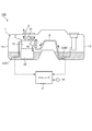
- FIG. 1 is a schematic configuration diagram of a fuel supply apparatus according to an embodiment of the present invention.
- FIG. 2 is a diagram illustrating the output characteristics of the fuel level sensor.
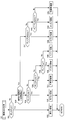
- FIG. 3 is a flowchart for explaining failure diagnosis of the fuel level sensor according to the embodiment of the present invention.
- FIG. 4 is a flowchart illustrating the remaining fuel amount region determination process.
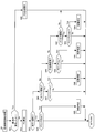
- FIG. 5 is a flowchart for explaining the region failure diagnosis process of the fuel level sensor.
- FIG. 1 is a schematic configuration diagram of a fuel supply apparatus 100 according to an embodiment of the present invention.
- Fuel supply device 100 is mounted on a vehicle or the like equipped with an engine.
- the fuel supply device 100 includes a fuel tank 1, a pump module 2, a fuel level sensor 3, and a controller 4.
- the fuel tank 1 is a vertical tank and includes a main tank 11 and a sub tank 12. The fuel in the fuel tank 1 is consumed from the fuel in the sub tank 12.
- the pump module 2 is provided in the main tank 11 and includes a fuel pump 21, a fuel filter 22, a pressure regulator 23, and a jet pump 24.
- the fuel pump 21 pumps up the fuel in the fuel tank 1 and supplies the fuel in the fuel tank 1 to the engine via the fuel pipe 5.
- the fuel filter 22 is provided downstream of the fuel pump 21.
- the fuel filter 22 removes foreign matters contained in the fuel in the fuel tank 1.
- the pressure regulator 23 keeps the pressure of the supplied fuel constant by returning the surplus fuel pumped up by the fuel pump 21 into the fuel tank 1.
- the jet pump 24 sucks up the fuel in the sub tank 12 using the negative pressure generated when the fuel returned from the pressure regulator 23 into the fuel tank 1 passes through the venturi inside the jet pump 24, It is sent to the main tank 11 through the transfer pipe 6.
- the fuel level sensor 3 includes a main sensor 31 attached to the pump module 2 and a sub sensor 32 attached to the sub tank 12, and detects the remaining amount of fuel in the fuel tank 1.
- the fuel level sensor 3 inputs a voltage value (hereinafter referred to as “level sensor output value”) FL corresponding to the remaining amount of fuel in the fuel tank 1 to the controller 4.
- the controller 4 includes a microcomputer having a central processing unit (CPU), a read only memory (ROM), a random access memory (RAM), and an input / output interface (I / O interface).
- the controller 4 receives detection signals from various sensors necessary for traveling of the vehicle such as the vehicle speed sensor 41 for detecting the vehicle speed.
- the controller 4 controls the engine based on the input detection signals of various sensors, and performs a failure diagnosis of the fuel level sensor 3.
- failure diagnosis of the fuel level sensor 3 is performed in consideration of the output characteristics of the fuel level sensor 3.
- FIG. 2 is a diagram for explaining the output characteristics of the fuel level sensor 3.
- the level sensor output value FL changes almost at a predetermined lower limit value FL ll in a region where the remaining amount of fuel is greater than the predetermined first remaining amount (hereinafter referred to as “full tank region”). Even in a region where the remaining fuel amount is less than the predetermined fourth remaining amount (hereinafter “empty region”), the predetermined upper limit value FL ul remains almost unchanged.
- the level sensor output value FL basically increases as the remaining fuel amount decreases.
- the region from the first remaining amount to the predetermined second remaining amount (hereinafter referred to as “sub tank region”) is a region where the fuel in the sub tank 12 is consumed.
- the region from the third remaining amount to the predetermined fourth remaining amount (hereinafter referred to as “main tank region”) is a region where the fuel in the main tank 11 is consumed.
- the change in the level sensor output value FL with respect to the change in the remaining amount of fuel is larger in the sub tank region than in the main tank region.
- the state in which the fuel in the sub tank 12 is consumed during the fuel consumption is switched to the state in which the fuel in the main tank 11 is consumed. .
- a “dead zone region” in which the level sensor output value FL hardly changes even when fuel is consumed occurs.
- the failure determination threshold is changed according to the remaining fuel amount region to suppress erroneous determination and to ensure the frequency of failure diagnosis.
- the failure diagnosis of the fuel level sensor 3 according to this embodiment will be described.
- FIG. 3 is a flowchart for explaining failure diagnosis of the fuel level sensor 3 according to the present embodiment.
- the controller 4 repeatedly executes this routine at a predetermined calculation cycle.
- step S1 the controller 4 determines whether a permission condition for performing a failure diagnosis of the fuel level sensor 3 is satisfied.
- the controller 4 ends the current process if the permission condition is not satisfied, and performs the process of step S2 if the permission condition is satisfied.
- the permission conditions include that the various sensors described above do not cause an obvious failure such as a disconnection or a short circuit, or that there is no abnormality in CAN communication.
- step S2 the controller 4 reads detection values of various sensors.
- step S3 the controller 4 performs an area determination process for the remaining amount of fuel. Details of the area determination processing will be described later with reference to FIG.
- step S4 based on the detected level sensor output value FL, the controller 4 updates the minimum value and the maximum value of the level sensor output value FL after a reset process described later is performed.
- the minimum value is basically the level sensor output value FL immediately after the reset process.
- the maximum value is basically updated every time the level sensor output value FL is detected because the level sensor output value FL increases as the fuel is consumed after the reset process is performed.
- step S ⁇ b> 5 the controller 4 performs a normal failure diagnosis process for the fuel level sensor 3. Specifically, it is determined whether or not the amount of change in the level sensor output value FL after the reset process is performed, that is, whether the difference between the maximum value and the minimum value is equal to or greater than a predetermined normal failure determination threshold value FL nor. To do. If the amount of change in the level sensor output value FL is greater than or equal to the normal failure determination threshold value FL nor , the controller 4 performs the process of step S6, and otherwise performs the process of step S8.
- step S6 the controller 4 determines that the fuel level sensor 3 is normal because the level sensor output value FL has changed.
- step S7 the controller 4 performs a reset process. Specifically, the minimum value and the maximum value of the level sensor output value FL are initialized.
- step S8 the controller 4 performs an area failure diagnosis process of the fuel level sensor 3 that is performed individually according to the area of the remaining fuel amount. Details of the region failure diagnosis processing of the fuel level sensor 3 will be described later with reference to FIG.
- step S9 the controller 4 determines whether or not the fuel level sensor 3 is determined to have failed in the region failure diagnosis process.
- the controller 4 performs the process of step S7 when the fuel level sensor 3 is determined to have failed in the region failure diagnosis process, and ends the current process otherwise.
- FIG. 4 is a flowchart illustrating the remaining fuel amount area determination process.
- step S31 the controller 4 determines whether or not the level sensor output value FL is equal to or lower than the lower limit value FLll . If the level sensor output value FL is equal to or lower than the lower limit value FLll , the controller 4 performs the process of step S32, and otherwise performs the process of step S33.
- step S32 the controller 4 determines that the area is full.
- step S33 the controller 4 determines whether or not the previous remaining fuel amount region is a dead zone region.
- the controller 4 performs the process of step S34 if the previous remaining fuel amount area is other than the dead zone area, and performs the process of step S41 if it is the dead zone area.
- step S34 the controller 4 determines whether or not the level sensor output value FL is less than the lower limit side dead zone determination threshold FL lldz (see FIG. 2).
- the controller 4 performs the process of step S35 if the level sensor output value FL is less than the lower limit side dead zone determination threshold FL lldz , and otherwise performs the process of step S36.
- step S35 the controller 4 determines that the sub tank area.
- step S36 the controller 4 determines whether or not the level sensor output value FL is equal to or less than the upper limit side dead zone determination threshold value FL uldz (see FIG. 2).
- the controller 4 performs the process of step S37 if the level sensor output value FL is equal to or less than the upper limit side dead zone determination threshold FL uldz , and otherwise performs the process of step S38.
- step S37 the controller 4 determines that it is a dead zone region.
- step S38 the controller 4 determines whether or not the level sensor output value FL is less than the upper limit value FLul .
- the controller 4 performs the process of step S39 if the level sensor output value FL is less than the upper limit value FL ul , and otherwise performs the process of step S40.
- step S39 the controller 4 determines that the main tank area.
- step S40 the controller 4 determines that the area is an empty area.
- step S41 the controller 4 determines whether or not the level sensor output value FL is less than a lower limit hysteresis threshold FL lldzhys obtained by subtracting a predetermined hysteresis value from the lower limit dead zone determination threshold FL lldz . If the level sensor output value FL is less than the lower limit hysteresis threshold FL lldzhys , the controller 4 performs the process of step S42, and otherwise performs the process of step S43.
- step S42 the controller 4 determines that the sub tank area.
- step S43 the controller 4 determines whether or not the level sensor output value FL is larger than an upper limit hysteresis threshold FL uldzhys obtained by adding a predetermined hysteresis value to the upper limit dead zone determination threshold FL uldz .
- the controller 4 performs the process of step S44 if the level sensor output value FL is larger than the upper limit hysteresis threshold FL uldzhys , and otherwise performs the process of step S45.
- step S44 the controller 4 determines that the main tank area.
- step S45 the controller 4 determines that it is a dead zone area. As described above, after entering the dead zone, the dead zone is determined until it falls out of a predetermined hysteresis range (FL lldzhys ⁇ FL ⁇ FL uldzhys ) in consideration of the influence of noise and the like.
- FIG. 5 is a flowchart for explaining the region failure diagnosis process of the fuel level sensor 3.
- step S81 the controller 4 determines whether or not the remaining fuel area has changed. Specifically, it is determined whether or not the fuel remaining area determined last time is different from the fuel remaining area determined this time. The controller 4 performs the process of step S95 if the region of the remaining fuel amount has changed, and performs the process of step S82 if it has not changed.
- step S82 the controller 4 calculates the travel distance after the remaining fuel amount region changes based on the vehicle speed and the like, and estimates the fuel consumption corresponding to the travel distance.
- the estimated fuel consumption is referred to as “estimated fuel consumption FC”.
- step S83 the controller 4 determines whether or not the remaining fuel area is a full tank area.
- the controller 4 performs the process of step S84 if it is a full area, and otherwise performs the process of step S86.
- step S84 the controller 4 determines whether or not the estimated fuel consumption FC has become larger than the full tank region failure determination threshold FC full .
- the full tank region failure determination threshold FC full is a value obtained by subtracting the first remaining amount from the full fuel, and if the fuel level sensor 3 is normal, the fuel corresponding to the full tank region failure determination threshold FC full is consumed. Is always a value at which the remaining fuel area is switched to the sub tank area.
- the controller 4 performs the process of step S86 if the estimated fuel consumption FC is greater than the full tank region failure determination threshold FC full , and if not, ends the current process.
- step S85 the controller 4 determines that the fuel level sensor 3 has failed, and returns the estimated fuel consumption FC to the initial value (zero).
- the reason why it is determined in step S85 that the fuel level sensor 3 has failed is as follows.
- step S5 Since the level sensor output value FL hardly changes in the full area, the change amount of the level sensor output value FL does not exceed the normal failure determination threshold value in step S5. However, if the fuel level sensor 3 is normal, when the fuel corresponding to the full tank region failure determination threshold FC full is consumed, the remaining fuel region should be switched to the sub tank region. Thus, despite the full area failure determination threshold value FC full amount of the fuel consumed (i.e. the estimated fuel consumption FC is greater than the full area failure determination threshold FC full), fuel quantity in step S81 If this step has been reached on the assumption that the region has not changed, it can be determined that the fuel level sensor 3 has failed.
- FC full area failure determination threshold value FC full amount of the fuel consumed i.e. the estimated fuel consumption FC is greater than the full area failure determination threshold FC full
- step S86 the controller 4 determines whether or not the remaining fuel area is the sub tank area. If it is a sub tank area, the controller 4 performs the process of step S87, and if not, performs the process of step S89.
- step S87 the controller 4 determines whether or not the estimated fuel consumption FC has become larger than the sub tank region failure determination threshold FC sub .
- the sub tank region failure determination threshold FC sub is a value corresponding to the fuel consumption required for the level sensor output value FL to change by the normal failure determination threshold in the sub tank region.
- the controller 4 performs the process of step S88 if the estimated fuel consumption FC is larger than the sub tank region failure determination threshold FC sub , and otherwise ends the current process.
- step S88 the controller 4 determines that the fuel level sensor 3 has failed, and returns the estimated fuel consumption FC to the initial value (zero).
- the reason why it is determined in step S88 that the fuel level sensor 3 has failed is as follows.
- the level sensor output value FL increases as the fuel is consumed. Therefore, if the fuel level sensor 3 is normal, the fuel corresponding to the sub tank region failure determination threshold FC sub is consumed (that is, the estimated fuel consumption FC is larger than the sub tank region failure determination threshold FC sub ).
- the amount of change in the level sensor output value FL should be greater than or equal to the normal failure determination threshold value. Nevertheless, in step S5, it is not determined that the amount of change in the level sensor output value FL is greater than or equal to the normal failure determination threshold value. When this step is reached, it can be determined that the fuel level sensor 3 has failed.
- step S89 the controller 4 determines whether or not the remaining fuel amount region is a dead zone region. If it is a dead zone area, the controller 4 performs the process of step S90, and if not, performs the process of step S92.
- step S90 the controller 4 determines whether or not the estimated fuel consumption FC is greater than the dead zone failure determination threshold FC dz .
- the dead zone failure determination threshold FC dz is a value that always switches the remaining fuel region to the main tank region when the fuel corresponding to the dead zone failure determination threshold FC dz is consumed if the fuel level sensor 3 is normal. . Accordingly, the dead zone failure determination threshold FC dz is approximately equal to a value obtained by subtracting the third remaining amount from the second remaining amount, and is a value set in consideration of the hysteresis range. If the estimated fuel consumption FC is larger than the dead zone failure determination threshold FC dz , the controller 4 performs the process of step S91, and if not, ends the current process.
- step S91 the controller 4 determines that the fuel level sensor 3 has failed, and returns the estimated fuel consumption FC to the initial value (zero).
- the reason why it is determined in step S91 that the fuel level sensor 3 has failed is as follows.
- the change amount of the level sensor output value FL does not exceed the normal failure determination threshold value in step S5.
- the fuel level sensor 3 is normal, when the fuel corresponding to the dead zone failure determination threshold FC dz is consumed, the remaining fuel region should be switched to the main tank region.
- FC dz amount of fuel consumed (i.e. the estimated fuel consumption FC is greater than the dead zone failure determination threshold value FC dz)
- the region of the fuel remaining amount in step S81 If this step is reached with no change, it can be determined that the fuel level sensor 3 has failed.
- step S92 the controller 4 determines whether or not the remaining fuel area is the main tank area. If it is the main tank region, the controller 4 performs the process of step S93, and if not, ends the current process.
- step S93 the controller 4 determines whether or not the estimated fuel consumption FC has become larger than the main tank region failure determination threshold FC main .
- the main tank region failure determination threshold value FC main is a value corresponding to the fuel consumption necessary for the level sensor output value FL to change by the normal failure determination threshold value in the main tank region.
- the controller 4 performs the process of step S94 if the estimated fuel consumption FC is larger than the main tank region failure determination threshold FC main , and otherwise ends the current process.
- step S94 the controller 4 determines that the fuel level sensor 3 has failed, and returns the estimated fuel consumption FC to the initial value (zero).
- the reason why it is determined in step S94 that the fuel level sensor 3 has failed is as follows.
- step S5 the change amount of the level sensor output value FL should be equal to or greater than the normal failure determination threshold value. Nevertheless, in step S5, it is not determined that the amount of change in the level sensor output value FL is greater than or equal to the normal failure determination threshold value. When this step is reached, it can be determined that the fuel level sensor 3 has failed.
- step S95 the controller 4 returns the estimated fuel consumption FC to the initial value (zero).
- the amount of change in the level sensor output value FL is periodically compared with a predetermined normal failure determination threshold value to perform failure diagnosis (normal failure diagnosis) of the fuel level sensor 3, and the fuel level.
- a failure diagnosis (region failure diagnosis) of the fuel level sensor 3 is individually performed for each region of the remaining amount of fuel divided based on the output characteristics of the sensor 3.
- the normal failure diagnosis is performed periodically, and the region failure diagnosis is performed individually for each region of the remaining amount of fuel, so that the number of times of the entire failure diagnosis of the fuel level sensor 3 can be increased.
- a failure determination threshold value corresponding to the output characteristics of the fuel level sensor 3 can be individually set for each remaining fuel area. Therefore, as in the present embodiment, in particular, when the output characteristic of the fuel level sensor 3 is an output characteristic having a dead zone, that is, the level sensor output value has a characteristic that hardly changes temporarily during fuel consumption. In such a case, by appropriately adjusting the failure determination threshold value in the dead zone region, it is possible to suppress erroneous determination and improve the accuracy of failure diagnosis.
- the failure determination threshold in the dead zone (dead zone failure determination threshold FC dz ) is set to a value corresponding to the fuel consumption necessary for exiting the dead zone. If the remaining fuel area is in the dead zone, the remaining fuel area is still in the dead zone even if the fuel consumption after entering the dead zone exceeds the fuel consumption required to exit the dead zone. It is determined that the fuel level sensor 3 is out of order when it is continuously determined that the region is present.
- the failure determination threshold values (sub-tank region failure determination threshold value FC sub and main tank region failure determination threshold value FC main ) in the sub tank region and the main tank region, and the level sensor output value FL in each region are normal failures. A value corresponding to the amount of fuel consumption required to change by the judgment threshold value was used.
- the fuel level sensor 3 exceeds the fuel consumption necessary for exiting the dead zone when performing the failure diagnosis of the fuel level sensor 3. There is no need to wait for fuel to be consumed. Therefore, when it is attempted to determine whether or not the level sensor output value FL has changed since the amount of fuel more than the fuel consumption necessary for passing through the dead zone is consumed in the entire region, the number of times of failure diagnosis is reduced.
- the failure determination threshold value in the dead zone region is distinguished from the failure determination threshold value in the sub tank region and the main tank region, and the failure determination threshold value in the sub tank region and the main tank region is compared with the failure determination threshold value in the dead zone region.
Landscapes
- Engineering & Computer Science (AREA)
- Chemical & Material Sciences (AREA)
- Combustion & Propulsion (AREA)
- Mechanical Engineering (AREA)
- General Engineering & Computer Science (AREA)
- Physics & Mathematics (AREA)
- Fluid Mechanics (AREA)
- General Physics & Mathematics (AREA)
- Combined Controls Of Internal Combustion Engines (AREA)
- Measurement Of Levels Of Liquids Or Fluent Solid Materials (AREA)
Abstract
Description
Claims (4)
- 少なくとも第1タンクと第2タンクとを備える燃料タンク内の燃料残量を検出する燃料レベルセンサの故障診断装置であって、
前記燃料レベルセンサの出力値に基づいて、前記燃料レベルセンサの出力特性に応じて区分けされた燃料残量の領域を判定する領域判定手段と、
前記領域が変化してからの燃料消費量と、前記領域ごとに個別に設定された故障判定閾値とを比較して、前記領域ごとに前記燃料レベルセンサの故障診断を行う領域故障診断手段と、
を備え、
前記領域故障診断手段は、
燃料消費先が前記第1タンクから前記第2タンクへと切り替わるときに燃料レベルセンサの出力値の変化が少なくなる不感帯領域において、前記故障判定閾値を、前記不感帯領域を抜けるために必要な燃料消費量相当の値とする、
燃料レベルセンサの故障診断装置。 - 前記領域に関係なく、前記燃料レベルセンサの変化量と、所定の通常故障判定閾値と、を定期的に比較して、前記燃料レベルセンサの故障診断を行う通常故障診断手段をさらに備える、
請求項1に記載の燃料レベルセンサの故障診断装置。 - 前記領域故障診断手段は、
前記領域が前記第1タンク又は前記第2タンクの燃料を消費する領域のときは、前記故障判定閾値を、その領域において前記燃料レベルセンサの出力値が前記通常故障判定閾値だけ変化するのに必要な燃料消費量相当の値とする、
請求項2に記載の燃料レベルセンサの故障診断装置。 - 少なくとも第1タンクと第2タンクとを備える燃料タンク内の燃料残量を検出する燃料レベルセンサの故障診断方法であって、
前記燃料レベルセンサの出力値に基づいて、前記燃料レベルセンサの出力特性に応じて区分けされた燃料残量の領域を判定する領域判定工程と、
前記領域が変化してからの燃料消費量と、前記領域ごとに個別に設定された故障判定閾値とを比較して、前記領域ごとに前記燃料レベルセンサの故障診断を行う領域故障診断工程と、
を備え、
前記領域故障診断工程は、
燃料消費先が前記第1タンクから前記第2タンクへと切り替わるときに燃料レベルセンサの出力値の変化が少なくなる不感帯領域において、前記故障判定閾値を、前記不感帯領域を抜けるために必要な燃料消費量相当の値とする、
燃料レベルセンサの故障診断方法。
Priority Applications (2)
| Application Number | Priority Date | Filing Date | Title |
|---|---|---|---|
| JP2014528082A JP5930043B2 (ja) | 2012-08-02 | 2013-07-23 | 燃料レベルセンサの故障診断装置及び燃料レベルセンサの故障診断方法 |
| US14/418,113 US9267835B2 (en) | 2012-08-02 | 2013-07-23 | Failure diagnosis apparatus for fuel level sensor and failure diagnosis method for fuel level sensor |
Applications Claiming Priority (2)
| Application Number | Priority Date | Filing Date | Title |
|---|---|---|---|
| JP2012-172258 | 2012-08-02 | ||
| JP2012172258 | 2012-08-02 |
Publications (1)
| Publication Number | Publication Date |
|---|---|
| WO2014021136A1 true WO2014021136A1 (ja) | 2014-02-06 |
Family
ID=50027816
Family Applications (1)
| Application Number | Title | Priority Date | Filing Date |
|---|---|---|---|
| PCT/JP2013/069862 Ceased WO2014021136A1 (ja) | 2012-08-02 | 2013-07-23 | 燃料レベルセンサの故障診断装置及び燃料レベルセンサの故障診断方法 |
Country Status (3)
| Country | Link |
|---|---|
| US (1) | US9267835B2 (ja) |
| JP (1) | JP5930043B2 (ja) |
| WO (1) | WO2014021136A1 (ja) |
Cited By (3)
| Publication number | Priority date | Publication date | Assignee | Title |
|---|---|---|---|---|
| US9822723B2 (en) | 2015-03-04 | 2017-11-21 | Denso Corporation | Fuel level sensor diagnosis device |
| JP2018031343A (ja) * | 2016-08-26 | 2018-03-01 | 株式会社デンソー | フィルタモジュール、および、これを用いた燃料ポンプモジュール |
| CN114323213A (zh) * | 2021-12-31 | 2022-04-12 | 河南长城信息技术有限公司 | 一种防止雷达式物位计故障引起设备跳停的方法 |
Families Citing this family (12)
| Publication number | Priority date | Publication date | Assignee | Title |
|---|---|---|---|---|
| SE537965C2 (sv) * | 2013-12-05 | 2015-12-15 | Scania Cv Ab | Förfarande och system för att fastställa en räckvidd för ettfordon |
| US9829370B2 (en) * | 2015-04-27 | 2017-11-28 | Ford Global Technologies, Llc | Methods and systems for fuel level indicators in a saddle fuel tank |
| US10312536B2 (en) | 2016-05-10 | 2019-06-04 | Hamilton Sundstrand Corporation | On-board aircraft electrochemical system |
| CN107476967B (zh) * | 2016-07-21 | 2019-07-19 | 宝沃汽车(中国)有限公司 | 燃油泵的检测方法及检测装置 |
| JP6625505B2 (ja) * | 2016-09-29 | 2019-12-25 | 本田技研工業株式会社 | 車両の残走行距離の表示装置 |
| CN108656951A (zh) * | 2017-03-31 | 2018-10-16 | 华晨汽车集团控股有限公司 | 一种汽车燃油表的控制方法 |
| US11131573B2 (en) * | 2017-12-01 | 2021-09-28 | GM Global Technology Operations LLC | Offset detection for fuel level sensor fault |
| FR3083608B1 (fr) * | 2018-07-06 | 2021-07-16 | Ifp Energies Now | Procede d'estimation d'une quantite de carburant reellement ajoutee lors d'un plein dans un reservoir de vehicule |
| US12179577B2 (en) * | 2018-12-28 | 2024-12-31 | Tf Technologies, Llc | Fuel measurement device with fuel passage and fuel level sensor |
| CN112918699B (zh) * | 2021-01-20 | 2024-02-09 | 上海海鹰机械厂 | 某型机消耗组信号灯提早燃亮的故障排除方法 |
| CN115076601B (zh) * | 2022-05-10 | 2024-02-20 | 潍柴动力股份有限公司 | 气罐剩余液位可信性的检测方法、装置及系统 |
| DE102024201578A1 (de) * | 2024-02-21 | 2025-08-21 | Schaeffler Technologies AG & Co. KG | Verfahren zur Diagnose einer Füllstands-Messvorrichtung |
Citations (3)
| Publication number | Priority date | Publication date | Assignee | Title |
|---|---|---|---|---|
| JPH0639549U (ja) * | 1992-11-05 | 1994-05-27 | 株式会社ワイエヌエス | 燃料残量検出装置 |
| JP2008514905A (ja) * | 2004-09-28 | 2008-05-08 | シーメンス アクチエンゲゼルシヤフト | 燃料タンク内に配置される1つまたは複数の充填レベルセンサの測定値を検査する方法ならびにこの方法を実施するための装置 |
| JP2008128068A (ja) * | 2006-11-20 | 2008-06-05 | Honda Motor Co Ltd | 燃料供給システム |
Family Cites Families (11)
| Publication number | Priority date | Publication date | Assignee | Title |
|---|---|---|---|---|
| JP2571571B2 (ja) * | 1986-06-23 | 1997-01-16 | 日産自動車株式会社 | 自動車用燃料検出装置 |
| JPH0655944A (ja) * | 1992-08-12 | 1994-03-01 | Toyota Motor Corp | 車両用燃料タンク |
| JPH06206454A (ja) * | 1993-01-11 | 1994-07-26 | Fujitsu Ten Ltd | サブタンクコントロールシステム |
| JPH10184479A (ja) | 1996-12-27 | 1998-07-14 | Hitachi Ltd | 燃料レベル検出手段の故障診断装置 |
| JP4163978B2 (ja) * | 2003-02-27 | 2008-10-08 | 新キャタピラー三菱株式会社 | 液体燃料量計測装置及び液体燃料量計測方法 |
| JP4560714B2 (ja) * | 2004-08-04 | 2010-10-13 | スズキ株式会社 | 内燃機関の燃料レベル制御装置 |
| JP2007132266A (ja) * | 2005-11-10 | 2007-05-31 | Toyota Motor Corp | 燃料貯留システム |
| US7631556B2 (en) * | 2006-08-01 | 2009-12-15 | Gm Global Technology Operations, Inc. | Empty fuel level detection cross-check |
| US7878057B2 (en) * | 2007-04-03 | 2011-02-01 | Gm Global Technology Operations, Inc. | System for detecting failures in fuel systems |
| US7739897B2 (en) * | 2007-04-03 | 2010-06-22 | Gm Global Technology Operations, Inc. | System for detecting failures in fuel systems |
| TW200840740A (en) * | 2007-04-13 | 2008-10-16 | Univ Mingchi Technology | Intelligent system and method for monitoring fuel quantity |
-
2013
- 2013-07-23 US US14/418,113 patent/US9267835B2/en active Active
- 2013-07-23 WO PCT/JP2013/069862 patent/WO2014021136A1/ja not_active Ceased
- 2013-07-23 JP JP2014528082A patent/JP5930043B2/ja active Active
Patent Citations (3)
| Publication number | Priority date | Publication date | Assignee | Title |
|---|---|---|---|---|
| JPH0639549U (ja) * | 1992-11-05 | 1994-05-27 | 株式会社ワイエヌエス | 燃料残量検出装置 |
| JP2008514905A (ja) * | 2004-09-28 | 2008-05-08 | シーメンス アクチエンゲゼルシヤフト | 燃料タンク内に配置される1つまたは複数の充填レベルセンサの測定値を検査する方法ならびにこの方法を実施するための装置 |
| JP2008128068A (ja) * | 2006-11-20 | 2008-06-05 | Honda Motor Co Ltd | 燃料供給システム |
Cited By (6)
| Publication number | Priority date | Publication date | Assignee | Title |
|---|---|---|---|---|
| US9822723B2 (en) | 2015-03-04 | 2017-11-21 | Denso Corporation | Fuel level sensor diagnosis device |
| JP2018031343A (ja) * | 2016-08-26 | 2018-03-01 | 株式会社デンソー | フィルタモジュール、および、これを用いた燃料ポンプモジュール |
| KR20190028805A (ko) * | 2016-08-26 | 2019-03-19 | 가부시키가이샤 덴소 | 필터 모듈 및 이를 이용한 연료 펌프 모듈 |
| CN109642526A (zh) * | 2016-08-26 | 2019-04-16 | 株式会社电装 | 过滤器模块以及使用该过滤器模块的燃料泵模块 |
| KR102116892B1 (ko) | 2016-08-26 | 2020-05-29 | 가부시키가이샤 덴소 | 필터 모듈 및 이를 이용한 연료 펌프 모듈 |
| CN114323213A (zh) * | 2021-12-31 | 2022-04-12 | 河南长城信息技术有限公司 | 一种防止雷达式物位计故障引起设备跳停的方法 |
Also Published As
| Publication number | Publication date |
|---|---|
| US9267835B2 (en) | 2016-02-23 |
| JP5930043B2 (ja) | 2016-06-08 |
| JPWO2014021136A1 (ja) | 2016-07-21 |
| US20150285670A1 (en) | 2015-10-08 |
Similar Documents
| Publication | Publication Date | Title |
|---|---|---|
| JP5930043B2 (ja) | 燃料レベルセンサの故障診断装置及び燃料レベルセンサの故障診断方法 | |
| KR101619597B1 (ko) | 후방 산소센서의 고장 검출 방법 | |
| CN105722728B (zh) | 电源控制系统 | |
| KR102294493B1 (ko) | 가변 오일펌프 시스템의 이상 진단방법 및 장치 | |
| US7878057B2 (en) | System for detecting failures in fuel systems | |
| US11223195B2 (en) | Control device and method for power supply to EPS in vehicle | |
| CN107851537A (zh) | 车载控制装置、车载控制系统 | |
| CN105896519A (zh) | 供电装置和具备该供电装置的车辆 | |
| KR20180050837A (ko) | 연료전지 시스템의 시동 제어 장치 및 방법 | |
| CA2909663C (en) | Fuel cell system and power generation monitoring method based on cathode gas deficiency | |
| KR101499997B1 (ko) | 릴레이 검사 장치 및 그의 구동 방법 | |
| KR101679961B1 (ko) | 연료전지 시스템의 압력센서 고장진단 방법 | |
| JP2009243304A (ja) | フィルタ目詰まり判定システムおよびフィルタ目詰まり判定装置 | |
| CN112349929B (zh) | 高压容器系统及其控制方法 | |
| CN108292920B (zh) | 电磁负载驱动装置以及车载控制系统 | |
| SE534537C2 (sv) | Fastställande av batterikondition | |
| EP2907995A1 (en) | Device and method for controlling engine | |
| JP6221829B2 (ja) | 燃料供給装置の異常診断装置 | |
| US10935576B2 (en) | Determination of operation status of shut-off element of battery module | |
| KR20150012476A (ko) | 비정상적인 암전류 발생 모듈 검출 장치 및 그 동작 방법 | |
| KR20140102533A (ko) | 차량의 러프로드 검출 시스템 및 그 방법 | |
| JP6402798B2 (ja) | 車両パワーウインドウ装置用の制御装置 | |
| KR20140023731A (ko) | 휠 굴삭기의 주행 제어 시스템 및 방법 | |
| JP5240415B2 (ja) | アルコール濃度センサの合理性診断装置 | |
| KR20090119487A (ko) | 바퀴 속도 센서의 라인 상태 검출 방법 |
Legal Events
| Date | Code | Title | Description |
|---|---|---|---|
| 121 | Ep: the epo has been informed by wipo that ep was designated in this application |
Ref document number: 13824964 Country of ref document: EP Kind code of ref document: A1 |
|
| ENP | Entry into the national phase |
Ref document number: 2014528082 Country of ref document: JP Kind code of ref document: A |
|
| WWE | Wipo information: entry into national phase |
Ref document number: 14418113 Country of ref document: US |
|
| NENP | Non-entry into the national phase |
Ref country code: DE |
|
| 122 | Ep: pct application non-entry in european phase |
Ref document number: 13824964 Country of ref document: EP Kind code of ref document: A1 |