WO2014021040A1 - 昇降ステップ装置 - Google Patents
昇降ステップ装置 Download PDFInfo
- Publication number
- WO2014021040A1 WO2014021040A1 PCT/JP2013/067998 JP2013067998W WO2014021040A1 WO 2014021040 A1 WO2014021040 A1 WO 2014021040A1 JP 2013067998 W JP2013067998 W JP 2013067998W WO 2014021040 A1 WO2014021040 A1 WO 2014021040A1
- Authority
- WO
- WIPO (PCT)
- Prior art keywords
- elevating
- lowering
- lifting
- raising
- step device
- Prior art date
- Legal status (The legal status is an assumption and is not a legal conclusion. Google has not performed a legal analysis and makes no representation as to the accuracy of the status listed.)
- Ceased
Links
Images








Classifications
-
- B—PERFORMING OPERATIONS; TRANSPORTING
- B60—VEHICLES IN GENERAL
- B60R—VEHICLES, VEHICLE FITTINGS, OR VEHICLE PARTS, NOT OTHERWISE PROVIDED FOR
- B60R3/00—Arrangements of steps or ladders facilitating access to or on the vehicle, e.g. running-boards
- B60R3/02—Retractable steps or ladders, e.g. movable under shock
-
- A—HUMAN NECESSITIES
- A61—MEDICAL OR VETERINARY SCIENCE; HYGIENE
- A61G—TRANSPORT, PERSONAL CONVEYANCES, OR ACCOMMODATION SPECIALLY ADAPTED FOR PATIENTS OR DISABLED PERSONS; OPERATING TABLES OR CHAIRS; CHAIRS FOR DENTISTRY; FUNERAL DEVICES
- A61G3/00—Ambulance aspects of vehicles; Vehicles with special provisions for transporting patients or disabled persons, or their personal conveyances, e.g. for facilitating access of, or for loading, wheelchairs
- A61G3/02—Loading or unloading personal conveyances; Facilitating access of patients or disabled persons to, or exit from, vehicles
- A61G3/06—Transfer using ramps, lifts or the like
- A61G3/062—Transfer using ramps, lifts or the like using lifts connected to the vehicle
-
- A—HUMAN NECESSITIES
- A61—MEDICAL OR VETERINARY SCIENCE; HYGIENE
- A61G—TRANSPORT, PERSONAL CONVEYANCES, OR ACCOMMODATION SPECIALLY ADAPTED FOR PATIENTS OR DISABLED PERSONS; OPERATING TABLES OR CHAIRS; CHAIRS FOR DENTISTRY; FUNERAL DEVICES
- A61G2200/00—Information related to the kind of patient or his position
- A61G2200/30—Specific positions of the patient
- A61G2200/36—Specific positions of the patient standing
Definitions
- the present invention relates to an elevating step device that is provided at an entrance of a vehicle and assists passengers to get on and off.
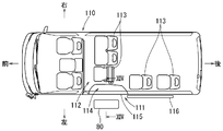
- an auxiliary step 80 as shown in FIGS. 12 to 14 is known as an elevating step device provided at a vehicle entrance / exit (see Japanese Patent Laid-Open No. 10-328239).
- the auxiliary step 80 is positioned between the road surface R and the vehicle step part 114 in the vehicle interior in the height direction, and has a configuration that protrudes outside the vehicle interior by a predetermined distance.
- a passenger who wants to get in from the vehicle entrance / exit 111 can move into the vehicle interior by sequentially transferring to the auxiliary step 80, the vehicle step unit 114, and the floor surface 112 of the vehicle interior so as to go up the stairs.
- Such an auxiliary step 80 is used for a passenger who is difficult to move directly from the road surface R to the vehicle step unit 114.
- an elevating step device that is provided at the entrance of a vehicle and assists the occupant to get on and off is configured to elevate and lower the step plate on which the occupant gets and the step plate between the road surface level and the floor level in the passenger compartment.
- an elevating mechanism configured to be possible.
- an elevating mechanism configured to be able to move the step plate up and down between a road surface level and a floor surface level in the passenger compartment. For this reason, the passenger
- the step board in the state in which the occupant is on is raised from the road surface level to the floor level in the passenger compartment by the lifting mechanism. For this reason, an occupant can easily get on.
- the passenger when the passenger gets off, the passenger can easily get off by lowering the step board on which the passenger is riding from the floor level in the passenger compartment to the road level. Therefore, when the occupant gets on and off the vehicle, the burden on the caregiver who assists the occupant can be reduced.
- a handrail portion that supports an occupant is connected to the step plate. For this reason, the occupant can stabilize the posture by gripping the handrail.
- the elevating mechanism includes a four-bar linkage mechanism and a drive unit that rotates the four-bar link mechanism up and down. For this reason, a step board can be raised / lowered horizontally.
- the elevating mechanism is configured to raise and lower the step plate by sliding the step plate obliquely. For this reason, it becomes easy to ensure the space between the head of the passenger
- the step plate is configured to be rotatable between a horizontal use position and an upright storage position.
- the step plate can be stored, the device storage space when the lifting step device is not used can be reduced.
- the handrail portion is provided with a protruding portion that protrudes toward the vehicle interior side with respect to the step plate. For this reason, the occupant has the protruding portion of the handrail in a forward tilted posture, and the occupant's head is naturally kept low while riding on the step board. Therefore, it is difficult for the passenger's head to hit the upper edge of the vehicle entrance.
- the support rail of the handrail is provided with an auxiliary seat that allows an occupant to sit. For this reason, a passenger
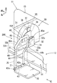
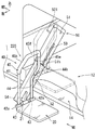
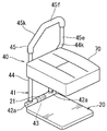
- FIG. 1 It is a schematic plan view of a vehicle provided with the raising / lowering step apparatus which concerns on 1st embodiment of this invention. It is a model side view of a vehicle provided with the raising / lowering step apparatus of 1st embodiment. It is a model rear view (III-III cross section arrow view of FIG. 1) of a vehicle provided with the raising / lowering step apparatus of 1st embodiment. It is a whole perspective view of the raising / lowering step apparatus of 1st embodiment. It is a schematic diagram showing the drive part of the raising / lowering step apparatus of 1st embodiment. It is a side view (VI arrow line view of FIG. 4) showing operation
- the elevating step device according to the present embodiment is provided at an entrance of a vehicle having a slide door.
- front and rear, right and left and up and down in the figure correspond to front and rear, left and right and up and down of the vehicle.
- a vehicle entrance 11 that is opened and closed by a slide door 16 is provided on the left side of a vehicle 10 having the lifting step device according to the present embodiment. Get on and off the vehicle 10 through the mouth 11.
- a vehicle seat 13 is installed at a predetermined position on the rear side of the front row seat 13f in the vehicle interior.
- a vehicle step portion 14 is provided at a position of the vehicle entrance 11 so as to be one step lower than the floor surface 12 in the passenger compartment.
- the raising / lowering step apparatus 200 which concerns on this embodiment is provided in the front side of the vehicle entrance / exit 11. As shown in FIG.
- the elevating step device 200 is a device that assists passengers to get on and off, and as shown in FIG. 4, the handrail portion 40, the step plate 20 connected to the lower end portion of the handrail portion 40, and the handrail portion 40. And an elevating mechanism 30 for elevating and lowering the step plate 20.
- the step board 20 is a board having a substantially rectangular shape for a passenger to get on. Between the use position horizontal to the road surface R and the stowed storage position (see the two-dot chain line). It connects with the lower end part of the handrail part 40 (it mentions later) so that vertical rotation is possible.
- a bearing portion 21 is provided at the front side position of the step plate 20.
- a connecting shaft 43 provided at the lower end of the step support portion 41 of the handrail portion 40 is passed through the bearing portion 21 of the step plate 20, and the bearing portion 21 and the connecting shaft 43 constitute a hinge structure. .
- the step plate 20 can be turned up and down as indicated by the arrows.
- the hinge structure is provided with a stopper (not shown), and the step plate 20 is restricted from rotating downward beyond the use position.
- the handrail portion 40 is a portion that supports the step plate 20 and is gripped by an occupant riding on the step plate 20, and includes a step support portion 41 and a handrail main body portion 45. It is configured.
- the step support portion 41 of the handrail portion 40 includes left and right vertical strut portions 44, a support plate portion 49 that connects the upper portions of the vertical strut portions 44, and a bearing portion 42a provided at the lower ends of both vertical strut portions 44.
- the connecting shaft 43 is supported. As described above, the connecting shaft 43 is passed through the bearing portion 21 of the step plate 20 and constitutes the hinge mechanism together with the bearing portion 21 of the step plate 20. Further, the vertical support 44 on the left side (outside the passenger compartment) stands upright, and the vertical support 44 on the right side (inside of the passenger compartment) stands up straight and is bent diagonally to the right at an intermediate position. The upper part is an inclined part 44k. And the upper part of the right and left vertical support
- a handrail main body 45 of the handrail portion 40 includes an inclined portion 45k extending obliquely upward to the right from the upper end of the left (outside) vertical support column portion 44, and horizontally rightward from the upper end of the inclined portion 45k. ) And a vertical bar portion 45e extending downward from the right end portion of the horizontal portion 45f and connected to the inclined portion 44k of the right vertical column portion 44.
- the handrail main body 45 comes to protrude toward the vehicle interior side with respect to the step plate 20.
- the right side part of the horizontal part 45f of the handrail main body part 45 and the upper side part of the vertical bar part 45e may be called a protrusion part.
- the elevating mechanism 30 includes a four-bar linkage mechanism 31 and a drive unit 35.
- the four-bar linkage mechanism 31 includes upper and lower two link arms 32 and 33 and an arm base 34 that supports the base ends of the two link arms 32 and 33 so as to be vertically rotatable.
- the tip ends of the upper and lower link arms 32, 33 are connected to the support plate portion 49 of the handrail portion 40 so as to be vertically rotatable by support shafts 32b, 33b, respectively. Further, the base end portions of the upper and lower link arms 32 and 33 are connected to an arm base portion 34 provided on the floor 12 in the passenger compartment so as to be vertically rotatable by support shafts 32a and 33a, respectively.
- a fan-shaped driven gear 36 of a drive unit 35 (described later) provided in parallel to the arm base 34 is arranged at the base end portion of the upper link arm 32 so that the center of rotation coincides with the link arm 32. So that it is fixed.
- the drive unit 35 includes the driven gear 36, a drive gear 37 that meshes with the driven gear 36, and a motor 38 that rotates the drive gear 37 forward and backward.
- the step plate 20 is at the level 12 on the floor surface, as shown by the two-dot chain line in FIG.
- a lowering switch (not shown) is operated to drive the motor 38 downward, and the driven gear 36 of the driving unit 35 is rotated counterclockwise.
- the upper link arm 32 and the lower link arm 33 rotate downward from the storage position, and the handrail portion 40 and the step plate 20 descend while holding the step plate 20 horizontally.
- the motor 38 stops. Thereby, the passenger
- An occupant in the state of riding on the step plate 20 can hold the forward tilt posture by gripping the protruding portion (right side position) of the handrail main body 45 of the handrail portion 40.
- a lift switch (not shown) is operated to drive the motor 38 to the lift side, and the driven gear 36 of the drive unit 35 is rotated clockwise.
- the upper link arm 32 and the lower link arm 33 rotate in the standing direction, and the handrail portion 40 and the step plate 20 rise while holding the step plate 20 horizontally.
- the motor 38 stops when the step plate 20 rises to the floor 12 level in the passenger compartment. As a result, the occupant can easily get on. After the occupant gets on the vehicle, the step plate 20 can be rotated upward about the connecting shaft 43 of the handrail portion 40 as needed to reach the stowed storage position.
- the elevating step device 200 provides the following advantages.
- the step plate 20 can be lifted and lowered between the road surface R level and the floor surface 12 level in the passenger compartment by the four-bar linkage mechanism 31 of the lifting mechanism 30. For this reason, the passenger
- the step board 20 in the state in which the occupant is riding rises from the road surface R level to the floor surface 12 level in the passenger compartment by the lifting mechanism 30. For this reason, an occupant can easily get on.
- the handrail portion 40 is provided on the step plate 20, the occupant can stabilize the posture when the step plate 20 is raised and lowered by gripping the handrail portion 40. Moreover, since the passenger
- step plate 20 can be stored, the device storage space when the lifting step device 200 is not used can be reduced.
- the elevating step device 220 according to the present embodiment is a modification of the elevating mechanism 30 of the elevating step device 200 according to the first embodiment, and the other structures are the same as those of the elevating step device 200 according to the first embodiment. is there. For this reason, the same number is attached
- the elevating mechanism 50 of the elevating step device 220 includes an inclined square tubular arm housing 51, a slide arm 52 that can be accommodated in the arm housing 51, and the slide arm 52 along the axis of the arm housing 51. And a drive unit 53 that moves up and down.
- the arm housing 51 of the elevating mechanism 50 is provided obliquely downward at the front end position of the vehicle entrance 11 as shown in FIGS. As shown in FIGS. 7 to 9, the arm housing 51 is formed in a substantially rectangular hollow box shape, and an opening 51h is provided on the lower end side.
- a slit 59 through which a connection bracket 54 (described later) passes along the axis from the position of the opening 51h is formed at the center of the front side (rear side) of the arm housing 51.
- a slide arm 52 and a drive unit 53 are housed inside the arm housing 51. Further, a motor 531 of the drive unit 53 is provided on the upper end side of the arm housing 51.
- the drive unit 53 includes a screw shaft 533 provided parallel to the axis of the arm housing 51, a transmission unit 532 that transmits the rotational force of the motor 531 to the screw shaft 533, and a screw shaft.
- the nut 534 is configured to be screwed with the nut 533 and move along the screw shaft 533 by the rotation of the screw shaft 533. Further, the nut 534 is connected to the proximal end portion of the slide arm 52 by the arm connecting portion 535.
- a connecting bracket 54 connected to the handrail 40 and the step plate 20 is provided at the tip of the slide arm 52.
- the connecting bracket 54 moves upward along the arm housing 51 together with the slide arm 52, it can pass through the slit 59 of the arm housing 51.
- the screw shaft 533 is reversely rotated by the motor 531 by operating a lift switch (not shown), the nut 534 moves upward along the screw shaft 533.
- the slide arm 52 moves upward along the arm housing 51 and is accommodated in the arm housing 51.
- the handrail portion 40 connected to the slide arm 52 and the step board 20 in the state in which the occupant is on are slid obliquely upward to the level of the floor 12 in the vehicle interior, as indicated by a two-dot chain line.
- the connecting bracket 54 passes through a slit 59 provided on the rear surface side of the arm housing 51.
- the elevating mechanism 50 of the elevating step device 220 is configured to raise and lower the step plate 20 by sliding the step plate 20 obliquely. For this reason, it becomes easy to ensure the space of the head of the passenger
- the lifting step device 230 according to the third embodiment of the present invention is obtained by adding an auxiliary seat 60 to the lifting step devices 200 and 220 according to the first and second embodiments of the present invention. This is the same as the lifting step device 200 according to the second embodiment. For this reason, about the same member as these, the same number is attached and explanation is omitted.
- the auxiliary seat portion 60 is configured so that an occupant riding on the step board 20 can sit on the vehicle while maintaining a forward leaning posture. That is, the auxiliary seat portion 60 has a substantially columnar shape, and protrudes in the horizontal direction from the vertical strut portion 44 on the left side (outside) of the handrail portion 40.
- the height position of the auxiliary seat 60 is provided below the occupant's waist and above the knee. As a result, the occupant sits on the auxiliary seat 60 while maintaining the forward leaning posture. For this reason, even an occupant with weak physical strength can safely get on and off using the elevating step device 230.
- pillar part 44 of the handrail part 40 may only be called a support
- the raising / lowering step apparatus which concerns on this invention, it is not limited to the structure of the raising / lowering step apparatus 200,220,230 of above-described 1st, 2nd, 3rd embodiment, A change is added suitably. It may be configured.
- the drive unit 35 is configured by the driven gear 36, the drive gear 37, and the motor 38.
- the upper and lower link arms 32 and 33 may be rotated by a hydraulic cylinder, for example.
- one end of the belt may be connected to the step plate 20 and the upper and lower link arms 32 and 33 may be rotated by winding or feeding the belt.
- the slide arm 52 may be provided with a second slide arm parallel to the slide arm 52 and a second drive unit that operates the second slide arm. That is, after the first slide arm 52 extends obliquely downward, the second slide arm extends obliquely downward, and the step plate 20 is lowered to the road surface R level.
- the length of each screw shaft and slide arm can be shortened. Accordingly, since the arm housing 51 can be reduced in size in the left-right direction, a space around the occupant's legs seated on the vehicle seat 13 can be secured.
- a configuration in which a folding sheet 70 on which an occupant can sit deeply can be added as an option is also possible.
- the lifting step devices 200, 220, and 230 are provided on the slide door 16 of the vehicle entrance 11 on the left side of the vehicle. You may provide in a sliding door. Further, the present invention can be applied not only to the sliding door but also to a back door, a folded door or the like.
Landscapes
- Health & Medical Sciences (AREA)
- Public Health (AREA)
- Engineering & Computer Science (AREA)
- Mechanical Engineering (AREA)
- Life Sciences & Earth Sciences (AREA)
- Animal Behavior & Ethology (AREA)
- General Health & Medical Sciences (AREA)
- Veterinary Medicine (AREA)
- Vehicle Step Arrangements And Article Storage (AREA)
Description
本発明は、車両の乗降口に設けられ、乗員の乗降を補助する昇降ステップ装置に関する。
車両の乗降口に設けられた昇降ステップ装置に関しては、例えば、図12から図14に示すような補助ステップ80が知られている(特開平10-328239号参照)。補助ステップ80は、使用時には、高さ方向において路面Rと車室内の車両ステップ部114との間に位置しており、車室外側に所定距離張り出す構成である。これによって、車両乗降口111から乗車しようとする乗員は、補助ステップ80、車両ステップ部114、車室内の床面112へと階段を上るように順次乗り移ることで、車室内に移動することができる。このような補助ステップ80は、路面Rから直接車両ステップ部114へと移動するのが困難な乗員に利用される。
しかし、補助ステップ80の高さまで足を上げられず、また、足を上げられたとしても体を持ち上げることができない乗員もいる。このような乗員が前記補助ステップを使用して乗車するためには、2~3名の介護者による補助が必要であり、介護者の負担が大きい。故に、乗員が容易に乗降できて、該乗員を補助する介護者の負担を軽減することが一般に望まれている。
本発明においては、車両の乗降口に設けられ、乗員の乗降を補助する昇降ステップ装置は、乗員が乗るステップ板と、前記ステップ板を、路面レベルと車室内の床面レベルとの間で昇降可能に構成された昇降機構とを有する。
本発明の1つの特徴においては、ステップ板を、路面レベルと車室内の床面レベルとの間で昇降可能に構成された昇降機構が設けられている。このため、昇降機構によりステップ板を路面レベルまで下降させることで、乗員は容易にステップ板に乗ることができる。乗員が乗った状態のステップ板は、昇降機構によって路面レベルから車室内の床面レベルまで上昇する。このため、乗員は容易に乗車できるようになる。
また、降車時において、乗員が乗った状態のステップ板を車室内の床面レベルから路面レベルまで下降させることで、乗員は容易に降車できるようになる。したがって、乗員が車両に乗降する際に、該乗員を補助する介護者の負担を軽減することができる。
本発明の他の特徴においては、ステップ板には、乗員を支える手摺り部が連結されている。このため、乗員は手摺り部を把持することで姿勢を安定させることができる。
本発明の他の特徴においては、昇降機構は、四節リンク機構と、前記四節リンク機構を上下回動させる駆動部とを備える。このため、ステップ板を水平に昇降できる。
本発明の他の特徴においては、昇降機構は、前記ステップ板を斜めにスライドさせることで、ステップ板を昇降させる構成である。このため、ステップ板に乗っている乗員の頭部と、車両乗降口上縁部との間のスペースを確保し易くなる。
本発明の他の特徴においては、ステップ板は、水平な使用位置と起立した格納位置間で回動可能に構成されている。このように、ステップ板を格納できるため、昇降ステップ装置を使用しないときの装置収納スペースを小さくできる。
本発明の他の特徴においては、手摺り部には、ステップ板に対して車室内側方向に突出する突出部が設けられている。このため、乗員は手摺り部の突出部を前傾姿勢で持ち、ステップ板に乗っている間、自然に乗員の頭部は低く保たれる。したがって、車両乗降口上縁部に乗員の頭部が当たり難くなる。
本発明の他の特徴においては、手摺り部の支柱には、乗員が腰掛可能な補助腰掛部が設けられている。このため、ステップ板に乗っている乗員が補助腰掛部に腰掛けることで、体力が低下した乗員でも姿勢が安定する。
以下、図1~図6に基づいて、本発明の第一実施形態に係る昇降ステップ装置の説明を行う。本実施形態に係る昇降ステップ装置は、スライドドアを有する車両の乗降口に設けられる。なお、図中の前後左右、及び上下は、車両の前後左右、及び上下に対応している。
図1~図3に示すように、本実施形態に係る昇降ステップ装置を有する車両10の左側側部にはスライドドア16によって開閉される車両乗降口11が設けられており、乗員はこの車両乗降口11を通って車両10に乗降する。車室内の前列シート13fの後側には、車両用シート13が所定位置に設置されている。また、車両乗降口11の位置には、車室内の床面12よりも一段低く形成された車両ステップ部14が設けられている。そして、車両乗降口11の前側に本実施形態に係る昇降ステップ装置200が設けられている。
昇降ステップ装置200は、乗員の乗降を補助する装置であり、図4に示すように、手摺り部40と、その手摺り部40の下端部に連結されたステップ板20と、手摺り部40及びステップ板20を昇降させる昇降機構30とを備えている。
ステップ板20は、図4に示すように、乗員が乗るための略長方形をした板であり、路面Rに対して水平な使用位置と、起立した格納位置(二点鎖線参照)との間で上下回動可能なように手摺り部40(後記する)の下端部に連結されている。ステップ板20の前辺位置には軸受部21が設けられている。ステップ板20の軸受部21には、手摺り部40のステップ支持部41の下端に設けられた連結軸43が通されており、軸受部21と連結軸43とによりヒンジ構造が構成されている。これによって、ステップ板20は矢印に示すように上下回動が可能である。また、前記ヒンジ構造には、ストッパー(図示しない)が設けられており、ステップ板20が使用位置を越えて下方向に回動しないように規制されている。
手摺り部40は、図4に示すように、前記ステップ板20を支持するとともに、そのステップ板20に乗った乗員が把持する部分であり、ステップ支持部41と、手摺り本体部45とから構成されている。
手摺り部40のステップ支持部41は、左右の縦支柱部44と、それらの縦支柱部44の上部をつなぐ支持板部49と、両縦支柱部44の下端に設けられた軸受部42aに支持される連結軸43とから構成されている。そして、前記連結軸43が、上記したように、ステップ板20の軸受部21に通されて、そのステップ板20の軸受部21と共に前記ヒンジ機構を構成する。また、左側(車室外側)の縦支柱部44は直線状に起立しており、右側(車室内側)の縦支柱部44は直線状に起立した後、途中位置で斜め右方向に曲げられており、その上部が傾斜部44kである。そして、左右の縦支柱部44の上部が壁状の支持板部49によって連結されている。
手摺り部40の手摺り本体部45は、左側(外側)の縦支柱部44の上端から斜め右上方に延びる傾斜部45kと、その傾斜部45kの上端から水平に右方向(車室内側方向)に延びる水平部45fと、その水平部45fの右端部から下方に延びて右側の縦支柱部44の傾斜部44kに接続される縦棒部45eとから構成されている。
これにより、手摺り本体部45は、ステップ板20に対して車室内側方向に突出するようになる。なお、手摺り本体部45の水平部45fの右側部と、縦棒部45eの上側部とは、突出部と呼ばれることもある。
昇降機構30は、四節リンク機構31と駆動部35とから構成されている。四節リンク機構31は、上下二本のリンクアーム32,33と、二本のリンクアーム32,33の基端部を上下回動可能に支持するアーム基部34とから構成されている。
図4に示すように、上下のリンクアーム32,33の先端部は、手摺り部40の支持板部49に、それぞれ支軸32b、33bによって上下回動可能に連結されている。また、上下のリンクアーム32,33の基端部は、車室内の床面12に設けられたアーム基部34に、それぞれ支軸32a、33aによって上下回動可能に連結されている。
さらに、上側のリンクアーム32の基端部には、アーム基部34に対して平行に設けられた駆動部35(後記する)の扇形の従動ギア36が、そのリンクアーム32と回転中心が一致するように固定されている。
駆動部35は、図5に示すように、前記従動ギア36と、従動ギア36に噛み合う駆動ギア37と、駆動ギア37を正逆回転させるモータ38とから構成されている。
モータ38の作動によって、従動ギア36が、駆動ギア37の噛み合いを通じて右方向に回転すると、従動ギア36と共に上側のリンクアーム32が支軸32aを中心にして上方向(右回り)に回動する。これによって、上側のリンクアーム32の先端と支軸32b、手摺り部40の支持板部49、及び支軸33bを介して連結された下側のリンクアーム33も支軸33aを中心に上方に回動する。これにより、手摺り部40とステップ板20とがそのステップ板20を水平に保持した状態で上昇する。
また、従動ギア36が左方向に回転すると、上側のリンクアーム32と下側のリンクアーム33とは下方向に回動し、手摺り部40とステップ板20とがそのステップ板20を水平に保持した状態で下降する。
昇降ステップ装置200が車室内に格納されている状態では、図6の二点鎖線で示すように、ステップ板20は床面12レベルにある。この状態から乗員を乗車させる場合、下降スイッチ(図示しない)を操作してモータ38を下降側に駆動させ、駆動部35の従動ギア36を左回りに回転させる。これにより、上側のリンクアーム32と下側のリンクアーム33とが格納位置から下方向に回動し、手摺り部40とステップ板20とがそのステップ板20を水平に保持した状態で下降する。
そして、ステップ板20が路面Rレベルまで下降した段階で、モータ38が停止する。これにより、乗員は容易にステップ板20に乗ることができる。ステップ板20に乗った状態で乗員は、手摺り部40の手摺り本体部45の突出部(右側位置)を把持することで、前傾姿勢を保持することができる。
次に、上昇スイッチ(図示しない)を操作してモータ38を上昇側に駆動させ、駆動部35の従動ギア36を右回りに回転させる。これにより、上側のリンクアーム32と下側のリンクアーム33とが起立方向に回動し、手摺り部40とステップ板20とがそのステップ板20を水平に保持した状態で上昇する。
そして、ステップ板20が車室内の床面12レベルまで上昇した段階で、モータ38が停止する。これによって、乗員は容易に乗車できるようになる。乗員が乗車した後は、必要に応じて、ステップ板20を、手摺り部40の連結軸43を中心に上方向に回動させて起立した格納位置にできる。
本実施形態に係る昇降ステップ装置200は次のような利点をもたらす。ステップ板20を昇降機構30の四節リンク機構31によって、路面Rレベルと車室内の床面12レベル間で昇降させることができる。このため、昇降機構30によりステップ板20を路面Rレベルまで下降させることで、乗員は容易にステップ板20に乗ることができる。乗員が乗った状態のステップ板20は、昇降機構30によって路面Rレベルから車室内の床面12レベルまで上昇する。このため、乗員は容易に乗車できるようになる。
また、ステップ板20には手摺り部40が設けられているため、乗員は手摺り部40を把持することでステップ板20の昇降時に姿勢を安定させることができる。また、乗員は手摺り部40の突出部(右側位置)を把持して姿勢を維持できるため、該乗員は自然に前傾姿勢になる。このため、ステップ板20に乗っている乗員の頭部と、車両乗降口上縁部15とのスペースを確保し易くなる。
また、ステップ板20を格納できるため、昇降ステップ装置200を使用しないときの装置収納スペースを小さくできる。
以下、図7~図9に基づいて、本発明の第二実施形態に係る昇降ステップ装置220の説明を行う。本実施形態に係る昇降ステップ装置220は、第一実施形態に係る昇降ステップ装置200の昇降機構30を改造したものであり、その他の構造については第一実施形態に係る昇降ステップ装置200と同様である。このため、第一実施形態に係る昇降ステップ装置200と同一部材については同一番号を付して説明を省略する。
本実施形態に係る昇降ステップ装置220の昇降機構50は、傾斜した角筒状のアームハウジング51と、アームハウジング51に収納可能なスライドアーム52と、スライドアーム52をアームハウジング51の軸心に沿って昇降させる駆動部53とから構成されている。
昇降機構50のアームハウジング51は、図7、図8に示すように、車両乗降口11の前端位置で斜め下向きに設けられている。アームハウジング51は、図7~図9に示すように、略長方形の中空箱状に形成されており、下端側に開口部51hが設けられている。
さらに、アームハウジング51の表面側(後面側)中央には、開口部51hの位置から軸心に沿って連結ブラケット54(後記する)が通過するスリット59が形成されている。また、アームハウジング51の内部には、スライドアーム52と、駆動部53とが収納されている。さらに、アームハウジング51の上端側には、駆動部53のモータ531が設けられている。
駆動部53は、図9に示すように、アームハウジング51の軸心に対して平行に設けられたネジ軸533と、モータ531の回転力をネジ軸533に伝達する伝達部532と、ネジ軸533と螺合し、そのネジ軸533の回転により、該ネジ軸533に沿って移動するナット534とから構成されている。さらに、ナット534は、アーム接続部535によって、スライドアーム52の基端部に接続されている。
スライドアーム52の先端部には、図7、図8に示すように、手摺り部40とステップ板20とに連結される連結ブラケット54が設けられている。そして、連結ブラケット54がスライドアーム52と共にアームハウジング51に沿って上方に移動する際に、そのアームハウジング51のスリット59を通過できる。
上記構成により、下降スイッチ(図示しない)を操作して、モータ531を下降方向に動作させると、ネジ軸533の回転によりナット534が前記ネジ軸533に沿って下方向に移動する。これにより、スライドアーム52がアームハウジング51に沿って下方向に移動し、アームハウジング51の開口部51hから斜め下方に伸長する。この結果、スライドアーム52に連結された手摺り部40とステップ板20とは、図7、図8の実線で示すように、スライドアーム52と共に斜め下方にスライド移動して、路面Rレベルまで下降するようになる。
また、上昇スイッチ(図示しない)を操作して、モータ531によりネジ軸533を逆回転させると、ナット534が前記ネジ軸533に沿って上方向に移動する。これにより、スライドアーム52がアームハウジング51に沿って上方向に移動し、そのアームハウジング51に収納されるようになる。この結果、スライドアーム52に連結された手摺り部40と乗員が乗った状態のステップ板20とは、二点鎖線で示すように、斜め上方にスライド移動して車室内の床面12レベルに上昇する。この時、連結ブラケット54はアームハウジング51の後面側に設けられたスリット59を通過する。
このように、昇降ステップ装置220の昇降機構50は、ステップ板20を斜めにスライドさせることで、ステップ板20を昇降させる構成である。このため、ステップ板20に乗っている乗員の頭部と、車両乗降口上縁部15とのスペースを確保し易くなり、乗員の頭部が当たるようなことがなくなる。
以下、図10に基づいて、本発明の第三実施形態に係る昇降ステップ装置230の説明を行う。本実施形態に係る昇降ステップ装置230は、本発明の第一、第二実施形態に係る昇降ステップ装置200、220に補助腰掛部60を追加したものであり、その他の構造については第一、第二実施形態に係る昇降ステップ装置200と同様である。このため、これらと同一部材については同一番号を付して説明を省略する。
補助腰掛部60は、ステップ板20に乗っている乗員が前傾姿勢を保持したまま腰掛けることができるように構成されている。即ち、補助腰掛部60は、略円柱状をしており、手摺り部40の左側(外側)の縦支柱部44から水平方向に張り出している。
補助腰掛部60の高さ位置は、乗員の腰よりも下方であって、膝よりも上方に設けられている。これにより、乗員は前傾姿勢を維持したまま補助腰掛部60に座る。このため、体力の衰えた乗員であっても、昇降ステップ装置230を利用して安全に乗降できる。なお、手摺り部40の縦支柱部44は単に支柱と呼ばれることもある。
なお、本発明に係る昇降ステップ装置にあっては、上記した第一、第二、第三実施形態の昇降ステップ装置200,220,230の構成に限定されるものではなく、適宜変更が加えられて構成されるものであってもよい。
例えば、第一実施形態では、上側のリンクアーム32を駆動部35により直接的に上下回動させる例を示したが、上側のリンクアーム32の代わりに下側のリンクアーム33を駆動部35により直接的に上下回動させる構成でも可能である。
また、第一実施形態では、駆動部35が、従動ギア36と、駆動ギア37と、モータ38とから構成される例を示した。しかし、例えば、油圧シリンダーによって上下のリンクアーム32、33を回動させる構成でも良い。また、ベルトの一端をステップ板20に連結し、このベルトの巻取りや繰出しによって上下のリンクアーム32、33を回動させる構成でも良い。
また、第二実施形態では、1つのネジ軸533と、1つのナット534とによって、1つのスライドアーム52を斜めに伸縮させる例を示した。しかし、例えば、スライドアーム52に、該スライドアーム52に平行な第2のスライドアームと、該第2のスライドアームを動作させる第2の駆動部とを設ける構成でも良い。即ち、第1のスライドアーム52が斜め下方に伸長した後に、第2のスライドアームが斜め下方に伸長し、ステップ板20を路面Rレベルに下降させる構成である。この変更例では、1つ1つのネジ軸とスライドアームとの長さを短くすることができる。したがって、アームハウジング51を左右方向に小型化できるので、車両シート13に着席する乗員の足回りのスペースを確保できる。
また、第一、第二実施形態において、図11に示すように、乗員が深く腰掛けることができる折り畳みシート70を、オプションとして追加する構成も可能である。
さらに、第一、第二、第三実施形態では、昇降ステップ装置200,220,230が車両左側の車両乗降口11のスライドドア16に設けられている例を示したが、例えば、車両右側のスライドドアに設けても良い。また、スライドドアに限らず、バックドアや、中折れドア等にも本発明を適用することが可能である。
Claims (7)
- 車両の乗降口に設けられ、乗員の乗降を補助する昇降ステップ装置であって、
乗員が乗るステップ板と、
前記ステップ板を、路面レベルと車室内の床面レベルとの間で昇降可能に構成された昇降機構とを有する昇降ステップ装置。 - 請求項1に記載された昇降ステップ装置であって、
前記ステップ板には、乗員を支える手摺り部が連結されている昇降ステップ装置。 - 請求項1又は2のいずれかに記載された昇降ステップ装置であって、
前記昇降機構は、四節リンク機構と、前記四節リンク機構を上下回動させる駆動部とを備える昇降ステップ装置。 - 請求項1又は2のいずれかに記載された昇降ステップ装置であって、
前記昇降機構は、前記ステップ板を斜めにスライドさせることで、前記ステップ板を昇降させる構成である昇降ステップ装置。 - 請求項1から4のいずれかに記載された昇降ステップ装置であって、
前記ステップ板は、水平な使用位置と起立した格納位置との間で回動可能に構成されている昇降ステップ装置。 - 請求項2から5のいずれかに記載された昇降ステップ装置であって、
前記手摺り部には、前記ステップ板に対して車室内側方向に突出する突出部が設けられている昇降ステップ装置。 - 請求項6に記載された昇降ステップ装置であって、
前記手摺り部の支柱には、乗員が腰掛可能な補助腰掛部が設けられている昇降ステップ装置。
Applications Claiming Priority (2)
| Application Number | Priority Date | Filing Date | Title |
|---|---|---|---|
| JP2012169703A JP2014028010A (ja) | 2012-07-31 | 2012-07-31 | 昇降ステップ装置 |
| JP2012-169703 | 2012-07-31 |
Publications (1)
| Publication Number | Publication Date |
|---|---|
| WO2014021040A1 true WO2014021040A1 (ja) | 2014-02-06 |
Family
ID=50027729
Family Applications (1)
| Application Number | Title | Priority Date | Filing Date |
|---|---|---|---|
| PCT/JP2013/067998 Ceased WO2014021040A1 (ja) | 2012-07-31 | 2013-07-01 | 昇降ステップ装置 |
Country Status (2)
| Country | Link |
|---|---|
| JP (1) | JP2014028010A (ja) |
| WO (1) | WO2014021040A1 (ja) |
Citations (3)
| Publication number | Priority date | Publication date | Assignee | Title |
|---|---|---|---|---|
| JPH0431049U (ja) * | 1990-07-06 | 1992-03-12 | ||
| JPH068058U (ja) * | 1992-07-07 | 1994-02-01 | 株式会社桜交通観光 | 座いす付き斜行機を備えたバス |
| JPH1148866A (ja) * | 1997-08-07 | 1999-02-23 | Fuji Heavy Ind Ltd | 乗降用リフトステップ装置を装備したバスの乗降口部構造 |
-
2012
- 2012-07-31 JP JP2012169703A patent/JP2014028010A/ja active Pending
-
2013
- 2013-07-01 WO PCT/JP2013/067998 patent/WO2014021040A1/ja not_active Ceased
Patent Citations (3)
| Publication number | Priority date | Publication date | Assignee | Title |
|---|---|---|---|---|
| JPH0431049U (ja) * | 1990-07-06 | 1992-03-12 | ||
| JPH068058U (ja) * | 1992-07-07 | 1994-02-01 | 株式会社桜交通観光 | 座いす付き斜行機を備えたバス |
| JPH1148866A (ja) * | 1997-08-07 | 1999-02-23 | Fuji Heavy Ind Ltd | 乗降用リフトステップ装置を装備したバスの乗降口部構造 |
Also Published As
| Publication number | Publication date |
|---|---|
| JP2014028010A (ja) | 2014-02-13 |
Similar Documents
| Publication | Publication Date | Title |
|---|---|---|
| WO2011007625A1 (ja) | 車両用シート | |
| US20110204688A1 (en) | Method and apparatus for supporting a wheelchair in a vehicle | |
| KR102235701B1 (ko) | 탑승기능을 가지는 휠체어 | |
| JP2014019212A (ja) | 車両の運転席用シート装置 | |
| JP5888155B2 (ja) | 車両用シート装置 | |
| JP6091853B2 (ja) | ベッド類の昇降装置及びこれを組み込んだストレッチャ | |
| JP5678847B2 (ja) | 車両シート装置 | |
| KR102235699B1 (ko) | 휠체어 이용자용 탑승장치 | |
| KR101423323B1 (ko) | 차량용 휠체어 이동 장치 | |
| KR20160129986A (ko) | 기립 보조장치 | |
| JP2013060089A (ja) | 車両シート装置 | |
| JP4632120B2 (ja) | 身体障害者車両用リフト装置 | |
| JP2017086950A (ja) | ベッド類の昇降装置及びこれを組み込んだストレッチャ | |
| JP2009160303A (ja) | 自動車用乗降補助装置 | |
| WO2014021040A1 (ja) | 昇降ステップ装置 | |
| JP5098118B2 (ja) | 車椅子収納装置及び車両 | |
| JP6511020B2 (ja) | 車椅子乗降装置 | |
| JP3042326B2 (ja) | 車両用シートの昇降装置 | |
| JP2005145281A (ja) | 車両の乗降補助装置 | |
| KR101759173B1 (ko) | 차량용 휠체어 가이드 장치 | |
| JP2014097134A (ja) | ベッド類の回転式サイドガード装置及びこれを組み込んだストレッチャ | |
| KR20160012634A (ko) | 차량용 휠체어 가이드 장치 | |
| JP4069920B2 (ja) | 車両用シート | |
| JP2006288436A (ja) | 車両用シートの乗降補助装置 | |
| KR20160012635A (ko) | 차량용 휠체어 가이드 장치 |
Legal Events
| Date | Code | Title | Description |
|---|---|---|---|
| 121 | Ep: the epo has been informed by wipo that ep was designated in this application |
Ref document number: 13824939 Country of ref document: EP Kind code of ref document: A1 |
|
| NENP | Non-entry into the national phase |
Ref country code: DE |
|
| 122 | Ep: pct application non-entry in european phase |
Ref document number: 13824939 Country of ref document: EP Kind code of ref document: A1 |