WO2014020689A1 - バッテリ充電装置、および、バッテリ充電方法 - Google Patents
バッテリ充電装置、および、バッテリ充電方法 Download PDFInfo
- Publication number
- WO2014020689A1 WO2014020689A1 PCT/JP2012/069431 JP2012069431W WO2014020689A1 WO 2014020689 A1 WO2014020689 A1 WO 2014020689A1 JP 2012069431 W JP2012069431 W JP 2012069431W WO 2014020689 A1 WO2014020689 A1 WO 2014020689A1
- Authority
- WO
- WIPO (PCT)
- Prior art keywords
- voltage
- battery
- switch element
- lamp
- terminal
- Prior art date
- Legal status (The legal status is an assumption and is not a legal conclusion. Google has not performed a legal analysis and makes no representation as to the accuracy of the status listed.)
- Ceased
Links
Images


Classifications
-
- B—PERFORMING OPERATIONS; TRANSPORTING
- B60—VEHICLES IN GENERAL
- B60Q—ARRANGEMENT OF SIGNALLING OR LIGHTING DEVICES, THE MOUNTING OR SUPPORTING THEREOF OR CIRCUITS THEREFOR, FOR VEHICLES IN GENERAL
- B60Q1/00—Arrangement of optical signalling or lighting devices, the mounting or supporting thereof or circuits therefor
- B60Q1/0088—Details of electrical connections
-
- H—ELECTRICITY
- H05—ELECTRIC TECHNIQUES NOT OTHERWISE PROVIDED FOR
- H05B—ELECTRIC HEATING; ELECTRIC LIGHT SOURCES NOT OTHERWISE PROVIDED FOR; CIRCUIT ARRANGEMENTS FOR ELECTRIC LIGHT SOURCES, IN GENERAL
- H05B47/00—Circuit arrangements for operating light sources in general, i.e. where the type of light source is not relevant
- H05B47/10—Controlling the light source
- H05B47/105—Controlling the light source in response to determined parameters
- H05B47/14—Controlling the light source in response to determined parameters by determining electrical parameters of the light source
-
- H—ELECTRICITY
- H02—GENERATION; CONVERSION OR DISTRIBUTION OF ELECTRIC POWER
- H02J—ELECTRIC POWER NETWORKS; CIRCUIT ARRANGEMENTS OR SYSTEMS FOR SUPPLYING OR DISTRIBUTING ELECTRIC POWER; SYSTEMS FOR STORING ELECTRIC ENERGY
- H02J2105/00—Networks for supplying or distributing electric power characterised by their spatial reach or by the load
- H02J2105/30—Networks for supplying or distributing electric power characterised by their spatial reach or by the load the load networks being external to vehicles, i.e. exchanging power with vehicles
-
- H—ELECTRICITY
- H02—GENERATION; CONVERSION OR DISTRIBUTION OF ELECTRIC POWER
- H02J—ELECTRIC POWER NETWORKS; CIRCUIT ARRANGEMENTS OR SYSTEMS FOR SUPPLYING OR DISTRIBUTING ELECTRIC POWER; SYSTEMS FOR STORING ELECTRIC ENERGY
- H02J7/00—Circuit arrangements for charging or discharging batteries or for supplying loads from batteries
- H02J7/14—Circuit arrangements for charging or discharging batteries or for supplying loads from batteries for charging batteries from dynamo-electric generators driven at varying speed, e.g. on vehicle
- H02J7/1469—Regulation of the charging current or voltage otherwise than by variation of field
- H02J7/1492—Regulation of the charging current or voltage otherwise than by variation of field by means of controlling devices between the generator output and the battery
Definitions
- the present invention relates to a battery charging device and a battery charging method.
- a battery charging device that supplies a power source for charging a battery and a power source for lighting a lamp such as a headlight using an AC voltage output of a generator driven by an engine such as a motorcycle.
- FIG. 5 is a diagram showing an example of the configuration of a conventional battery charging system 1000A.
- FIG. 6 is a diagram showing an example of operation waveforms of the conventional battery charger 100A shown in FIG.
- a battery charger 100A used in a conventional battery charging system 1000A includes a generator terminal TA to which a coil of a single-phase AC generator A is connected between the ground and the ground.
- a lamp terminal TL to which the lamp L is connected a battery terminal TB to which the battery B is connected between the ground, a ground terminal TE connected to the ground, a first thyristor S1, and a second thyristor S2.
- the second thyristor S2 is turned on when the output voltage of the generator terminal TA has a positive polarity and the battery voltage of the battery B is less than the specified voltage. As a result, the positive component of the output voltage of the single-phase AC generator A is supplied to the battery B, and the battery B is charged (X in FIG. 6). At this time, the output voltage is the sum of the battery voltage V BAT and the voltage VT S2 of the second thyristor S2.
- the first thyristor S1 is turned on when the effective value (or average voltage) of the lamp voltage of the lamp L is lower than the target voltage when the output voltage of the generator terminal TA has a negative polarity. Thereby, the negative component of the output voltage of the single-phase AC generator A is supplied to the lamp L (Y in FIG. 6).
- the effective voltage (or average voltage) of the lamp voltage decreases.
- the ON time of the second thyristor S2 becomes longer for charging the battery B, it becomes impossible to sufficiently supply power to the lamp L via the first thyristor S1. That is, the brightness of the lamp L is lowered.
- the brightness of the lamp L may be reduced due to a change in the load of the lamp L or the like.
- a battery charger includes: A battery charging device for controlling charging of a battery and power supply of a lamp by a single-phase AC generator, A generator terminal to which the coil of the single-phase AC generator is connected between ground and A lamp terminal to which the lamp is connected between the ground and the ground; A battery terminal to which the battery is connected between the ground and A first switching element having a first node connected to the lamp terminal and a second node connected to the generator terminal; A second switch element having a first node connected to the generator terminal and a second node connected to the battery terminal; A third switch element having a first node connected to the generator terminal and a second node connected to the lamp terminal; A control circuit that outputs a signal to the gates of the first to third switch elements to control the operation of the first to third switch elements; In the case where the output voltage of the generator terminal output from the single-phase AC generator is a first polarity, The control circuit turns on the first switch element when a comparison value that is an effective value or an average value of the
- the first switch element is a first thyristor;
- the second switch element is a second thyristor;
- the third switch element may be a third thyristor.
- the first polarity of the output voltage is a negative polarity of the output voltage;
- the second polarity of the output voltage is a positive polarity of the output voltage;
- the first node of the first to third thyristors is an anode;
- the second node of the first to third thyristors is a cathode;
- the control circuit includes: Turning off the second thyristor and the third thyristor; When the comparison value is less than the target voltage, the first thyristor is turned on. On the other hand, when the comparison value is greater than or equal to the target voltage, the first thyristor is turned off.
- the control circuit includes: Turning off the first thyristor; When the comparison value is less than the threshold voltage, the third thyristor is turned on. On the other hand, when the comparison value is greater than or equal to the threshold voltage, the third thyristor is turned off. When the battery voltage of the battery is lower than the specified voltage, the second thyristor may be turned on. On the other hand, when the battery voltage of the battery is equal to or higher than the specified voltage, the second thyristor may be turned off. .
- the size of the third thyristor may be smaller than the size of the first thyristor.
- the control circuit includes: An arithmetic circuit that detects a lamp voltage of the lamp terminal, calculates and outputs the comparison value that is an effective value or an average value of the detected lamp voltage; A threshold voltage generation circuit that generates and outputs the threshold voltage; A differential voltage generation circuit that generates a differential voltage and outputs the target voltage obtained by adding the differential voltage to the threshold voltage; A signal is output to the gate of the first switch element according to a result of comparing the comparison value output from the arithmetic circuit and the target voltage output from the differential voltage generation circuit, and the polarity of the output voltage. A first comparison circuit; A signal is output to the gate of the third switch element according to a result of comparing the comparison value output from the arithmetic circuit with the threshold voltage output from the threshold voltage generation circuit and the polarity of the output voltage. A second comparison circuit.
- the first comparison circuit In the battery charger, In the case where the output voltage is the first polarity, The first comparison circuit outputs a signal to the gate of the first switch element to turn on the first switch element when the comparison value is less than the target voltage, while the comparison value is When the voltage is equal to or higher than the target voltage, a signal is output to the gate of the first switch element so as to turn off the first switch element; The second comparison circuit outputs a signal to a gate of the third switch element so as to turn off the third switch element; In the case where the output voltage is the second polarity, The first comparison circuit outputs a signal to the gate of the first switch element so as to turn off the first switch element, and the second comparison circuit is configured to output the signal when the comparison value is less than the threshold voltage. A signal is output to the gate of the third switch element to turn on the third switch element, and when the comparison value is equal to or higher than the threshold voltage, the third switch element is turned off. A signal may be output to the gate of the third switch element.
- a battery charging method includes: A battery charging device for controlling charging of a battery and power supply of a lamp by a single-phase alternating current generator, wherein a generator terminal to which a coil of the single-phase alternating current generator is connected between the ground and the ground A lamp terminal to which the lamp is connected; a battery terminal to which the battery is connected to the ground; a first node connected to the lamp terminal; and a second node connected to the generator terminal.
- a battery charging method by a battery charging device comprising: a third switch element having a second node connected to the lamp terminal;
- the comparison value which is the effective value or average value of the lamp voltage at the lamp terminal
- the first switch element is turned on
- the second polarity When the comparison value is less than a threshold voltage lower than the target voltage, the third switch element is turned on, and when the battery voltage of the battery is less than a specified voltage, the second switch element is turned on.
- the battery charger controls battery charging and lamp power supply by a single-phase AC generator.
- a battery is connected between a generator terminal to which a coil of a single-phase AC generator is connected to ground, a lamp terminal to which a lamp is connected to ground, and ground.
- a battery terminal having a cathode connected to the generator terminal and an anode connected to the lamp terminal; a second thyristor having an anode connected to the generator terminal and a cathode connected to the battery terminal;
- a third thyristor having an anode connected to the generator terminal and a cathode connected to the lamp terminal, and a control circuit for controlling the operation of the first to third thyristors.
- the control circuit determines that the effective value or average value of the lamp voltage at the lamp terminal is less than the target voltage.
- the first thyristor is turned on.
- the control circuit turns on the third thyristor when the comparison value is lower than the threshold voltage lower than the target voltage, and the second when the battery voltage of the battery is lower than the specified voltage. Turn on the thyristor.
- the effective value or average value of the lamp voltage can be brought closer to the target voltage more quickly.
- the battery charger according to one aspect of the present invention, it is possible to suppress a decrease in brightness of the lamp while charging the battery by the single-phase AC generator.
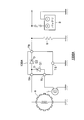
- FIG. 1 is a diagram illustrating an example of a configuration of a battery charging system 1000 according to a first embodiment which is an aspect of the present invention.
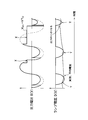
- FIG. 2 is a waveform diagram showing an example of operation waveforms of the battery charger 100 shown in FIG.
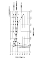
- FIG. 3 is a diagram illustrating an example of the relationship between the rotation speed of the single-phase AC generator A and the effective value of the lamp voltage when the battery B is fully charged.
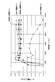
- FIG. 4 is a diagram illustrating an example of a relationship between the rotation speed of the single-phase AC generator A and the effective value of the lamp voltage in a state where the battery B is charged (the battery voltage is less than the specified voltage).
- FIG. 5 is a diagram showing an example of the configuration of a conventional battery charging system 1000A.
- FIG. 6 is a diagram showing an example of operation waveforms of the conventional battery charger 100A shown in FIG.
- the anode of the thyristor is the first node
- the cathode of the thyristor is the second node
- the negative polarity of the output voltage of the single-phase AC generator is the first polarity
- the positive voltage of the output voltage of the single-phase AC generator is The polarity will be described as the second polarity.
- the anode of the thyristor is the second node
- the cathode of the thyristor is the first node
- the negative polarity of the output voltage of the single-phase AC generator is the second polarity
- the positive polarity of the output voltage of the single-phase AC generator is the second node. The same applies to the case of one polarity.
- FIG. 1 is a diagram illustrating an example of a configuration of a battery charging system 1000 according to a first embodiment which is an aspect of the present invention.
- the battery charging system 1000 includes a battery B, a load R, a single-phase AC generator A, and a battery charging device 100.
- the single-phase AC generator A has a coil having one end connected to the ground and the other end connected to the generator terminal TA of the battery charger 100.
- the single-phase AC generator A generates an AC voltage for charging the battery B and lights the lamp L, and supplies the AC voltage from the output terminal.
- This single-phase AC generator A is, for example, an alternator that is directly connected to a motorcycle engine.
- the battery B has a + terminal (positive side) and a ⁇ terminal (negative side), and can be charged / discharged via these terminals. Note that the negative side of the battery B is connected to the ground, and the positive side of the battery B is connected to the battery terminal TB of the battery charger 100.
- the battery B is, for example, a motorcycle battery.
- the lamp L has one end connected to the ground and the other end connected to the lamp terminal TL of the battery charger 100.
- the lamp L is, for example, a lamp such as a motorcycle headlight or tail lamp. In this case, the load of the lamp L fluctuates (increases) due to the operation of a high beam or the like.
- the load R is connected between the ground and the battery terminal TB.
- the load R is, for example, a vehicle load such as a device that requires a power source in a motorcycle.
- the battery charging device 100 rectifies the alternating current output from the output terminal of the single-phase alternating current generator A, and controls the charging of the battery B and the lighting of the lamp L (power supply) by the single-phase alternating current generator A. It is like that.
- the battery charging device 100 includes, for example, a generator terminal TA, a lamp terminal TL, a battery terminal TB, a ground terminal TE, and a first thyristor (first switch element). S1, a second thyristor (second switch element) S2, a third thyristor (third switch element) S3, and a control circuit CON.
- the coil of the single-phase AC generator A is connected between the generator terminal TA and the ground.
- the lamp L is connected between the lamp terminal TL and the ground.
- the battery B is connected between the battery terminal TB and the ground.
- the ground terminal TE is connected to the ground.
- the first thyristor S1 has an anode (first node) connected to the lamp terminal TL and a cathode (second node) connected to the generator terminal TA.
- the first thyristor S1 has a target value that is an effective value or an average value of the lamp voltage of the lamp L when the output voltage of the generator terminal TA has a negative polarity (first polarity). Turns on when the voltage is lower. As a result, the negative component of the output voltage of the single-phase AC generator A is supplied to the lamp L.
- the second thyristor S2 has an anode (first node) connected to the generator terminal TA and a cathode (second node) connected to the battery terminal TB.
- the second thyristor S2 is turned on when the output voltage of the generator terminal TA has a positive polarity (second polarity) and the battery voltage of the battery B is less than the specified voltage. .
- the positive component of the output voltage of the single-phase AC generator A is supplied to the battery B, and the battery B is charged.
- the second thyristor S2 is turned off when the output voltage is positive and the battery voltage of the battery B is equal to or higher than the specified voltage. Thereby, the battery B is not overcharged.
- the third thyristor S3 has an anode (first node) connected to the generator terminal TA and a cathode (second node) connected to the lamp terminal TL.
- the third thyristor S3 is a comparison that is an effective value or an average value of the lamp voltage of the lamp L when the output voltage of the generator terminal TA has a positive polarity, as will be described later. Turns on only when the value is lower than the threshold voltage. As a result, the positive component of the output voltage of the single-phase AC generator A is supplied to the lamp L. That is, at least a part of the positive component of the output voltage that should be supplied to the battery B is supplied to the lamp L.
- the third thyristor S3 performs an auxiliary operation to bring the effective value or average value of the lamp voltage closer to the target voltage when the effective value or average value of the lamp voltage is lower than the threshold voltage. It is. Therefore, the capacity of the third thyristor S3 may be smaller than the capacity of the first thyristor S1.
- the size of the third thyristor S3 is set to be smaller than the size of the first thyristor S1.
- control circuit CON outputs signals to the gates of the first to third thyristors S1, S2, and S3 based on the voltages of the terminals TA, TL, TB, and TE, so that the first to third The operation of the thyristors S1, S2, and S3 is controlled.
- the control circuit CON detects the battery voltage of the battery B based on the voltages of the battery terminal TB and the ground terminal TE, for example.
- control circuit CON calculates a comparison value that is an effective value or an average value of the lamp voltage of the lamp terminal TL based on, for example, the voltage of the lamp terminal TL and the ground terminal TE. For example, the control circuit CON calculates an effective value or an average value of the potential difference between the lamp terminal TL and the ground terminal TE, and outputs the calculated value as a comparison value.
- the control circuit CON detects the polarity of the voltage at the generator terminal TA (the output voltage of the single-phase AC generator A) based on the voltage at the generator terminal TA and the ground terminal TE, for example. .
- the control circuit CON detects the polarity of the voltage at the generator terminal TA (the output voltage of the single-phase AC generator A) from the potential relationship between the generator terminal TA and the ground terminal TE.
- the control circuit CON includes an arithmetic circuit AC, a threshold voltage generation circuit TVG, a differential voltage generation circuit DVG, a first comparison circuit C1, and a second comparison circuit C2. And a battery voltage adjustment circuit BC.
- the arithmetic circuit AC detects the lamp voltage at the lamp terminal TL, and calculates and outputs a comparison value that is an effective value or an average value of the detected lamp voltage.
- the threshold voltage generation circuit TVG generates and outputs a threshold voltage.
- the differential voltage generation circuit DVG generates a differential voltage and outputs a target voltage obtained by adding the differential voltage to the threshold voltage.
- the first comparison circuit C1 compares the comparison value output from the arithmetic circuit AC with the target voltage output from the differential voltage generation circuit DVG, and the voltage at the generator terminal TA (the output voltage of the single-phase AC generator A). ), A signal is output to the gate of the first thyristor S1.
- the first comparison circuit C1 when the output voltage has a negative polarity, the first comparison circuit C1 outputs a signal to the gate of the first thyristor S1 so as to turn on the first thyristor S1 when the comparison value is less than the target voltage.
- the comparison value when the comparison value is equal to or higher than the target voltage, a signal is output to the gate of the first thyristor S1 so as to turn off the first thyristor S1.
- the first comparison circuit C1 outputs a signal to the gate of the first thyristor S1 so as to turn off the first thyristor S1.
- the second comparison circuit C2 compares the comparison value output from the arithmetic circuit AC with the threshold voltage output from the threshold voltage generation circuit TVG, and the voltage at the generator terminal TA (the output voltage of the single-phase AC generator A). ), A signal is output to the gate of the third thyristor S3.
- the second comparison circuit C2 when the output voltage has a negative polarity, the second comparison circuit C2 outputs a signal to the gate of the third thyristor S3 so as to turn off the third thyristor S3.
- the second comparison circuit C2 When the output voltage has a positive polarity, the second comparison circuit C2 outputs a signal to the gate of the third thyristor S3 so as to turn on the third thyristor S3 when the comparison value is less than the threshold voltage. On the other hand, when the comparison value is equal to or higher than the threshold voltage, a signal is output to the gate of the third thyristor S3 that turns off the third thyristor S3.
- the battery voltage adjustment circuit BC outputs a signal to the gate of the second thyristor S2 in accordance with the polarity of the battery voltage and the voltage of the generator terminal TA (the output voltage of the single-phase AC generator A). .
- the battery voltage adjustment circuit BC when the output voltage has a negative polarity, the battery voltage adjustment circuit BC outputs a signal to the gate of the second thyristor S2 so as to turn off the second thyristor S2.
- the battery voltage adjustment circuit BC when the output voltage has a positive polarity, the battery voltage adjustment circuit BC outputs a signal to the gate of the second thyristor S2 so as to turn on the second thyristor S2 when the battery voltage is less than the specified voltage.
- a signal is output to the gate of the second thyristor S2 so as to turn off the second thyristor S2.
- FIG. 2 is a waveform diagram showing an example of operation waveforms of the battery charging apparatus 100 shown in FIG.
- the comparison value may be an average value of the lamp voltage.
- the control circuit CON sets the lamp of the lamp terminal TL. Since the comparison value that is the effective value of the voltage is less than the target voltage (time t0), the first thyristor S1 is turned on (time t1 to t2).
- the control circuit CON turns off the second thyristor S2 and the third thyristor S3 (time t0 to t2).
- the control circuit CON does not show the battery voltage of the battery B, which is not shown here, but the second thyristor S2 Is turned on (time t3 to t4).
- the output voltage is the sum of the battery voltage V BAT and the voltage VT S2 of the second thyristor S2.
- the positive component of the output voltage of the single-phase AC generator A is supplied to the battery B, and the battery B is charged.
- the control circuit CON turns off the third thyristor S3 because the comparison value (effective value) is equal to or higher than the threshold voltage (time t2). (Time t2 to t4).
- control circuit CON turns off the first thyristor S1.
- the control circuit CON determines that the first thyristor S1 has a comparison value (effective value) less than the target voltage (time t4). Is turned on (time t4 to t5).
- control circuit CON turns off the second thyristor S2 and the third thyristor S3 (time t4 to t5).
- the control circuit CON does not show the battery voltage of the battery B, which is not shown here, but the second thyristor S2 Is turned on (time t6 to t8).
- the positive component of the output voltage of the single-phase AC generator A is supplied to the battery B, and the battery B is charged.
- the control circuit CON turns on the third thyristor S3 because the comparison value (effective value) is less than the threshold voltage (time t5). (Time t7 to t8).
- the positive component of the output voltage of the single-phase AC generator A is supplied to the lamp L.
- the effective value of the lamp voltage can be made closer to the target voltage.
- control circuit CON turns off the first thyristor S1.
- the control circuit CON turns off the second thyristor S2 when the battery voltage of the battery B is equal to or higher than the specified voltage. Thereby, the battery B is not overcharged.
- the battery charging device 100 repeats the same operation, thereby charging the battery B to the specified voltage and maintaining the effective value or average value of the lamp voltage closer to the vicinity of the target voltage.
- FIG. 3 is a diagram showing an example of the relationship between the rotation speed of the single-phase AC generator A and the effective value of the lamp voltage when the battery B is fully charged.
- FIG. 4 is a diagram illustrating an example of the relationship between the rotation speed of the single-phase AC generator A and the effective value of the lamp voltage in a state where the battery B is charged (the battery voltage is less than the specified voltage). .
- the third thyristor S3 supplies power to the lamp L. Therefore, the effective value of the lamp voltage hardly decreases (FIGS. 3 and 4).
- the battery charger controls battery charging and lamp power supply by the single-phase AC generator.
- a battery is connected between a generator terminal to which a coil of a single-phase AC generator is connected to ground, a lamp terminal to which a lamp is connected to ground, and ground.
- a battery terminal having a cathode connected to the generator terminal and an anode connected to the lamp terminal; a second thyristor having an anode connected to the generator terminal and a cathode connected to the battery terminal;
- a third thyristor having an anode connected to the generator terminal and a cathode connected to the lamp terminal, and a control circuit for controlling the operation of the first to third thyristors.
- the control circuit determines that the effective value or average value of the lamp voltage at the lamp terminal is less than the target voltage.
- the first thyristor is turned on.
- the control circuit turns on the third thyristor when the comparison value is lower than the threshold voltage lower than the target voltage, and the second when the battery voltage of the battery is lower than the specified voltage. Turn on the thyristor.
- the negative component of the output voltage of the single-phase AC generator is supplied to the lamp. Furthermore, when the effective value or average value of the lamp voltage is less than the threshold voltage, at least a part of the positive component of the output voltage of the single-phase AC generator is supplementarily supplied to the lamp.
- the lamp voltage when the lamp voltage fluctuates due to fluctuations in the lamp load, the lamp voltage can be brought closer to the target voltage more quickly.
- the battery charger according to one aspect of the present invention, it is possible to suppress a decrease in brightness of the lamp while charging the battery by the single-phase AC generator.
- the anode of the thyristor is the first node
- the cathode of the thyristor is the second node
- the negative polarity of the output voltage of the single-phase AC generator is the first polarity
- the single-phase AC power generation The positive polarity of the output voltage of the machine has been described as the second polarity.
- the anode of the thyristor is the second node
- the cathode of the thyristor is the first node
- the negative polarity of the output voltage of the single-phase AC generator is the second polarity
- the positive polarity of the output voltage of the single-phase AC generator is the second node.
- One polarity may be used.
- power may be supplied to the lamp with a positive component of the output voltage, and the lamp may be supplementarily supplied with power while charging the battery with a negative component of the output voltage.
- thyristor is selected as the switching element.
- MOS transistor may be selected as the switching element.
Landscapes
- Engineering & Computer Science (AREA)
- Mechanical Engineering (AREA)
- Control Of Charge By Means Of Generators (AREA)
- Control Of Eletrric Generators (AREA)
- Charge And Discharge Circuits For Batteries Or The Like (AREA)
- Circuit Arrangement For Electric Light Sources In General (AREA)
- Secondary Cells (AREA)
Abstract
Description
単相交流発電機によるバッテリの充電およびランプの電源供給を制御するバッテリ充電装置であって、
接地との間に前記単相交流発電機のコイルが接続される発電機端子と、
前記接地との間に前記ランプが接続されるランプ端子と、
前記接地との間に前記バッテリが接続されるバッテリ端子と、
前記ランプ端子に第1ノードが接続され、前記発電機端子に第2ノードが接続された第1のスイッチ素子と、
前記発電機端子に第1ノードが接続され、前記バッテリ端子に第2ノードが接続された第2のスイッチ素子と、
前記発電機端子に第1ノードが接続され、前記ランプ端子に第2ノードが接続された第3のスイッチ素子と、
前記第1から第3のスイッチ素子のゲートに信号を出力して前記第1から第3のスイッチ素子の動作を制御する制御回路と、を備え、
前記単相交流発電機から出力された前記発電機端子の出力電圧が第1極性の場合において、
前記制御回路は、前記ランプ端子のランプ電圧の実効値又は平均値である比較値が目標電圧未満のときには、前記第1のスイッチ素子をオンし、
一方、前記出力電圧が第2極性の場合において、
前記制御回路は、前記比較値が前記目標電圧よりも低い閾値電圧未満ときには、前記第3のスイッチ素子をオンし、前記バッテリのバッテリ電圧が規定電圧未満のときには、前記第2のスイッチ素子をオンする
ことを特徴とする。
前記第1のスイッチ素子は、第1のサイリスタであり、
前記第2のスイッチ素子は、第2のサイリスタであり、
前記第3のスイッチ素子は、第3のサイリスタであるようにしてもよい。
前記出力電圧の前記第1極性は、前記出力電圧の負の極性であり、
前記出力電圧の前記第2極性は、前記出力電圧の正の極性であり、
前記第1から第3のサイリスタの前記第1ノードは、アノードであり、
前記第1から第3のサイリスタの前記第2ノードは、カソードであり、
前記出力電圧が前記第1極性の場合において、
前記制御回路は、
前記第2のサイリスタおよび前記第3のサイリスタをオフし、
前記比較値が前記目標電圧未満のときには、前記第1のサイリスタをオンし、一方、前記比較値が前記目標電圧以上のときには、前記第1のサイリスタをオフし、
前記出力電圧が前記第2極性の場合において、
前記制御回路は、
前記第1のサイリスタをオフし、
前記比較値が前記閾値電圧未満ときには、前記第3のサイリスタをオンし、一方、前記比較値が前記閾値電圧以上のときには、前記第3のサイリスタをオフし、
前記バッテリのバッテリ電圧が前記規定電圧未満のときには、前記第2のサイリスタをオンし、一方、前記バッテリのバッテリ電圧が前記規定電圧以上のときには、前記第2のサイリスタをオフする
ようにしてもよい。
前記第3のサイリスタのサイズは、前記第1のサイリスタのサイズよりも小さくしてもよい。
前記制御回路は、
前記ランプ端子のランプ電圧を検出し、検出された前記ランプ電圧の実効値又は平均値である前記比較値を演算し出力する演算回路と、
前記閾値電圧を生成し出力する閾値電圧生成回路と、
差分電圧を生成し、前記閾値電圧に前記差分電圧を加算することにより得られた前記目標電圧を出力する差分電圧生成回路と、
前記演算回路が出力した前記比較値と前記差分電圧生成回路が出力した前記目標電圧とを比較した結果、および前記出力電圧の極性に応じて、前記第1のスイッチ素子のゲートに信号を出力する第1の比較回路と、
前記演算回路が出力した前記比較値と前記閾値電圧生成回路が出力した前記閾値電圧とを比較した結果、および前記出力電圧の極性に応じて、前記第3のスイッチ素子のゲートに信号を出力する第2の比較回路と、を有するようにしてもよい。
前記出力電圧が前記第1極性の場合において、
前記第1の比較回路は、前記比較値が前記目標電圧未満のときには、前記第1のスイッチ素子をオンするように前記第1のスイッチ素子のゲートに信号を出力し、一方、前記比較値が前記目標電圧以上のときには、前記第1のスイッチ素子をオフするように前記第1のスイッチ素子のゲートに信号を出力し、
前記第2の比較回路は、前記第3のスイッチ素子をオフするように前記第3のスイッチ素子のゲートに信号を出力し、
前記出力電圧が前記第2極性の場合において、
前記第1の比較回路は、前記第1のスイッチ素子をオフするように前記第1のスイッチ素子のゲートに信号を出力し、 前記第2の比較回路は、前記比較値が前記閾値電圧未満ときには、前記第3のスイッチ素子をオンするように前記第3のスイッチ素子のゲートに信号を出力し、一方、前記比較値が前記閾値電圧以上のときには、前記第3のスイッチ素子をオフする前記第3のスイッチ素子のゲートに信号を出力するようにしてもよい。
単相交流発電機によるバッテリの充電およびランプの電源供給を制御するバッテリ充電装置であって、接地との間に前記単相交流発電機のコイルが接続される発電機端子と、前記接地との間に前記ランプが接続されるランプ端子と、前記接地との間に前記バッテリが接続されるバッテリ端子と、前記ランプ端子に第1ノードが接続され、前記発電機端子に第2ノードが接続された第1のスイッチ素子と、前記発電機端子に第1ノードが接続され、前記バッテリ端子に第2ノードが接続された第2のスイッチ素子と、前記発電機端子に第1ノードが接続され、前記ランプ端子に第2ノードが接続された第3のスイッチ素子と、を備えたバッテリ充電装置によるバッテリ充電方法であって、
前記単相交流発電機から出力された前記発電機端子の出力電圧が第1極性の場合において、
前記ランプ端子のランプ電圧の実効値又は平均値である比較値が目標電圧未満のときには、前記第1のスイッチ素子をオンし、
一方、前記出力電圧が第2極性の場合において、
前記比較値が前記目標電圧よりも低い閾値電圧未満ときには、前記第3のスイッチ素子をオンし、前記バッテリのバッテリ電圧が規定電圧未満のときには、前記第2のスイッチ素子をオンすることを特徴とする。
Claims (7)
- 単相交流発電機によるバッテリの充電およびランプの電源供給を制御するバッテリ充電装置であって、
接地との間に前記単相交流発電機のコイルが接続される発電機端子と、
前記接地との間に前記ランプが接続されるランプ端子と、
前記接地との間に前記バッテリが接続されるバッテリ端子と、
前記ランプ端子に第1ノードが接続され、前記発電機端子に第2ノードが接続された第1のスイッチ素子と、
前記発電機端子に第1ノードが接続され、前記バッテリ端子に第2ノードが接続された第2のスイッチ素子と、
前記発電機端子に第1ノードが接続され、前記ランプ端子に第2ノードが接続された第3のスイッチ素子と、
前記第1から第3のスイッチ素子のゲートに信号を出力して前記第1から第3のスイッチ素子の動作を制御する制御回路と、を備え、
前記単相交流発電機から出力された前記発電機端子の出力電圧が第1極性の場合において、
前記制御回路は、前記ランプ端子のランプ電圧の実効値又は平均値である比較値が目標電圧未満のときには、前記第1のスイッチ素子をオンし、
一方、前記出力電圧が第2極性の場合において、
前記制御回路は、前記比較値が前記目標電圧よりも低い閾値電圧未満ときには、前記第3のスイッチ素子をオンし、前記バッテリのバッテリ電圧が規定電圧未満のときには、前記第2のスイッチ素子をオンする
ことを特徴とするバッテリ充電装置。 - 前記第1のスイッチ素子は、第1のサイリスタであり、
前記第2のスイッチ素子は、第2のサイリスタであり、
前記第3のスイッチ素子は、第3のサイリスタであることを特徴とする請求項1に記載のバッテリ充電装置。 - 前記出力電圧の前記第1極性は、前記出力電圧の負の極性であり、
前記出力電圧の前記第2極性は、前記出力電圧の正の極性であり、
前記第1から第3のサイリスタの前記第1ノードは、アノードであり、
前記第1から第3のサイリスタの前記第2ノードは、カソードであり、
前記出力電圧が前記第1極性の場合において、
前記制御回路は、
前記第2のサイリスタおよび前記第3のサイリスタをオフし、
前記比較値が前記目標電圧未満のときには、前記第1のサイリスタをオンし、一方、前記比較値が前記目標電圧以上のときには、前記第1のサイリスタをオフし、
前記出力電圧が前記第2極性の場合において、
前記制御回路は、
前記第1のサイリスタをオフし、
前記比較値が前記閾値電圧未満ときには、前記第3のサイリスタをオンし、一方、前記比較値が前記閾値電圧以上のときには、前記第3のサイリスタをオフし、
前記バッテリのバッテリ電圧が前記規定電圧未満のときには、前記第2のサイリスタをオンし、一方、前記バッテリのバッテリ電圧が前記規定電圧以上のときには、前記第2のサイリスタをオフする
ことを特徴とする請求項2に記載のバッテリ充電装置。 - 前記第3のサイリスタのサイズは、前記第1のサイリスタのサイズよりも小さいことを特徴とする請求項2に記載のバッテリ充電装置。
- 前記制御回路は、
前記ランプ端子のランプ電圧を検出し、検出された前記ランプ電圧の実効値又は平均値である前記比較値を演算し出力する演算回路と、
前記閾値電圧を生成し出力する閾値電圧生成回路と、
差分電圧を生成し、前記閾値電圧に前記差分電圧を加算することにより得られた前記目標電圧を出力する差分電圧生成回路と、
前記演算回路が出力した前記比較値と前記差分電圧生成回路が出力した前記目標電圧とを比較した結果、および前記出力電圧の極性に応じて、前記第1のスイッチ素子のゲートに信号を出力する第1の比較回路と、
前記演算回路が出力した前記比較値と前記閾値電圧生成回路が出力した前記閾値電圧とを比較した結果、および前記出力電圧の極性に応じて、前記第3のスイッチ素子のゲートに信号を出力する第2の比較回路と、を有する
ことを特徴とする請求項1または2に記載のバッテリ充電装置。 - 前記出力電圧が前記第1極性の場合において、
前記第1の比較回路は、前記比較値が前記目標電圧未満のときには、前記第1のスイッチ素子をオンするように前記第1のスイッチ素子のゲートに信号を出力し、一方、前記比較値が前記目標電圧以上のときには、前記第1のスイッチ素子をオフするように前記第1のスイッチ素子のゲートに信号を出力し、
前記第2の比較回路は、前記第3のスイッチ素子をオフするように前記第3のスイッチ素子のゲートに信号を出力し、
前記出力電圧が前記第2極性の場合において、
前記第1の比較回路は、前記第1のスイッチ素子をオフするように前記第1のスイッチ素子のゲートに信号を出力し、
前記第2の比較回路は、前記比較値が前記閾値電圧未満ときには、前記第3のスイッチ素子をオンするように前記第3のスイッチ素子のゲートに信号を出力し、一方、前記比較値が前記閾値電圧以上のときには、前記第3のスイッチ素子をオフする前記第3のスイッチ素子のゲートに信号を出力する
ことを特徴とする請求項5に記載のバッテリ充電装置。 - 単相交流発電機によるバッテリの充電およびランプの電源供給を制御するバッテリ充電装置であって、接地との間に前記単相交流発電機のコイルが接続される発電機端子と、前記接地との間に前記ランプが接続されるランプ端子と、前記接地との間に前記バッテリが接続されるバッテリ端子と、前記ランプ端子に第1ノードが接続され、前記発電機端子に第2ノードが接続された第1のスイッチ素子と、前記発電機端子に第1ノードが接続され、前記バッテリ端子に第2ノードが接続された第2のスイッチ素子と、前記発電機端子に第1ノードが接続され、前記ランプ端子に第2ノードが接続された第3のスイッチ素子と、を備えたバッテリ充電装置によるバッテリ充電方法であって、
前記単相交流発電機から出力された前記発電機端子の出力電圧が第1極性の場合において、
前記ランプ端子のランプ電圧の実効値又は平均値である比較値が目標電圧未満のときには、前記第1のスイッチ素子をオンし、
一方、前記出力電圧が第2極性の場合において、
前記比較値が前記目標電圧よりも低い閾値電圧未満ときには、前記第3のスイッチ素子をオンし、前記バッテリのバッテリ電圧が規定電圧未満のときには、前記第2のスイッチ素子をオンする
ことを特徴とするバッテリ充電方法。
Priority Applications (6)
| Application Number | Priority Date | Filing Date | Title |
|---|---|---|---|
| JP2013500680A JP5442905B1 (ja) | 2012-07-31 | 2012-07-31 | バッテリ充電装置、および、バッテリ充電方法 |
| MYPI2013701368A MY166324A (en) | 2012-07-31 | 2012-07-31 | Battery charging apparatus and battery charging method |
| BR112013021715A BR112013021715A2 (pt) | 2012-07-31 | 2012-07-31 | aparelho de carregamento da bateria e método de carregamento da bateria |
| PCT/JP2012/069431 WO2014020689A1 (ja) | 2012-07-31 | 2012-07-31 | バッテリ充電装置、および、バッテリ充電方法 |
| CN201280003581.3A CN103733730B (zh) | 2012-07-31 | 2012-07-31 | 蓄电池充电装置以及蓄电池充电方法 |
| TW102114188A TWI483511B (zh) | 2012-07-31 | 2013-04-22 | The battery charging apparatus and battery charging method |
Applications Claiming Priority (1)
| Application Number | Priority Date | Filing Date | Title |
|---|---|---|---|
| PCT/JP2012/069431 WO2014020689A1 (ja) | 2012-07-31 | 2012-07-31 | バッテリ充電装置、および、バッテリ充電方法 |
Publications (1)
| Publication Number | Publication Date |
|---|---|
| WO2014020689A1 true WO2014020689A1 (ja) | 2014-02-06 |
Family
ID=50027421
Family Applications (1)
| Application Number | Title | Priority Date | Filing Date |
|---|---|---|---|
| PCT/JP2012/069431 Ceased WO2014020689A1 (ja) | 2012-07-31 | 2012-07-31 | バッテリ充電装置、および、バッテリ充電方法 |
Country Status (6)
| Country | Link |
|---|---|
| JP (1) | JP5442905B1 (ja) |
| CN (1) | CN103733730B (ja) |
| BR (1) | BR112013021715A2 (ja) |
| MY (1) | MY166324A (ja) |
| TW (1) | TWI483511B (ja) |
| WO (1) | WO2014020689A1 (ja) |
Cited By (1)
| Publication number | Priority date | Publication date | Assignee | Title |
|---|---|---|---|---|
| JP6637636B1 (ja) * | 2018-09-07 | 2020-01-29 | 新電元工業株式会社 | レギュレータ及び出力電圧制御方法 |
Citations (2)
| Publication number | Priority date | Publication date | Assignee | Title |
|---|---|---|---|---|
| JP2005329922A (ja) * | 2004-04-23 | 2005-12-02 | Yamaha Motor Co Ltd | ヘッドライト点灯装置 |
| JP2012115071A (ja) * | 2010-11-25 | 2012-06-14 | Shindengen Electric Mfg Co Ltd | バッテリ充電装置、および、バッテリ充電システム |
Family Cites Families (5)
| Publication number | Priority date | Publication date | Assignee | Title |
|---|---|---|---|---|
| CN88202349U (zh) * | 1988-03-25 | 1988-12-14 | 中国人民解放军重庆通信学院 | 车用集成化多功能发电机调节器 |
| JPH10313545A (ja) * | 1997-05-08 | 1998-11-24 | Mitsuba Corp | バッテリ充電及びランプ点灯制御回路 |
| JP4107816B2 (ja) * | 2001-08-01 | 2008-06-25 | 新電元工業株式会社 | 発電機の電圧調整装置 |
| CN100572139C (zh) * | 2005-05-02 | 2009-12-23 | 新电元工业株式会社 | 蓄电池充电和亮灯控制电路 |
| EP1993196B1 (en) * | 2006-03-09 | 2018-09-19 | Shindengen Electric Manufacturing Co., Ltd. | Power conversion device and method, and triangular wave generation circuit |
-
2012
- 2012-07-31 BR BR112013021715A patent/BR112013021715A2/pt not_active IP Right Cessation
- 2012-07-31 JP JP2013500680A patent/JP5442905B1/ja active Active
- 2012-07-31 WO PCT/JP2012/069431 patent/WO2014020689A1/ja not_active Ceased
- 2012-07-31 CN CN201280003581.3A patent/CN103733730B/zh active Active
- 2012-07-31 MY MYPI2013701368A patent/MY166324A/en unknown
-
2013
- 2013-04-22 TW TW102114188A patent/TWI483511B/zh active
Patent Citations (2)
| Publication number | Priority date | Publication date | Assignee | Title |
|---|---|---|---|---|
| JP2005329922A (ja) * | 2004-04-23 | 2005-12-02 | Yamaha Motor Co Ltd | ヘッドライト点灯装置 |
| JP2012115071A (ja) * | 2010-11-25 | 2012-06-14 | Shindengen Electric Mfg Co Ltd | バッテリ充電装置、および、バッテリ充電システム |
Cited By (2)
| Publication number | Priority date | Publication date | Assignee | Title |
|---|---|---|---|---|
| JP6637636B1 (ja) * | 2018-09-07 | 2020-01-29 | 新電元工業株式会社 | レギュレータ及び出力電圧制御方法 |
| WO2020049735A1 (ja) * | 2018-09-07 | 2020-03-12 | 新電元工業株式会社 | レギュレータ及び出力電圧制御方法 |
Also Published As
| Publication number | Publication date |
|---|---|
| TW201406002A (zh) | 2014-02-01 |
| MY166324A (en) | 2018-06-25 |
| JPWO2014020689A1 (ja) | 2016-07-11 |
| JP5442905B1 (ja) | 2014-03-19 |
| TWI483511B (zh) | 2015-05-01 |
| CN103733730B (zh) | 2015-07-15 |
| CN103733730A (zh) | 2014-04-16 |
| BR112013021715A2 (pt) | 2016-11-01 |
Similar Documents
| Publication | Publication Date | Title |
|---|---|---|
| US9376056B2 (en) | Power supply device and illumination device for vehicle using same | |
| US9537402B2 (en) | Electric power converter | |
| JP6138354B2 (ja) | 負荷駆動回路、および、負荷短絡検出回路 | |
| JP5749244B2 (ja) | Ledランプ点灯装置、及び制御方法 | |
| US9537414B2 (en) | Power conversion apparatus that switches electrode connection when a short-circuit is detected | |
| CN109716867B (zh) | 调光装置的保护电路及调光装置 | |
| TWI657718B (zh) | 調光裝置 | |
| US10104728B2 (en) | LED driving circuit, LED device comprising the same, and driving method of LED | |
| JP6062602B1 (ja) | Led駆動回路 | |
| JPWO2020144796A1 (ja) | 電力変換装置 | |
| JP5442905B1 (ja) | バッテリ充電装置、および、バッテリ充電方法 | |
| JP2004140886A (ja) | スイッチングレギュレータ回路、及び車両用灯具 | |
| JPWO2015079580A1 (ja) | 電源装置 | |
| JP2020039204A (ja) | 駆動対象スイッチの駆動回路 | |
| JP2014121245A (ja) | バッテリ充電装置、及び制御方法 | |
| WO2016039212A1 (ja) | 充電装置 | |
| JPWO2014061127A1 (ja) | Ledランプ点灯制御回路、および、ledランプ点灯制御方法 | |
| JP5778019B2 (ja) | バッテリ充電装置及びバッテリ充電システム | |
| JP5418287B2 (ja) | エンジンの発電システム | |
| WO2024195731A1 (ja) | 過電流抑制装置 | |
| KR20240111920A (ko) | 모터 제어 회로 | |
| JP2017158295A (ja) | バッテリシステム制御装置 | |
| WO2016189581A1 (ja) | 車両用ledランプ点灯回路、車両用ledランプ点灯装置、および車両用ledランプ点灯回路の制御方法 | |
| JP2021096980A (ja) | 点灯装置および照明器具 | |
| JPWO2014181459A1 (ja) | バッテリ充電装置およびバッテリ充電制御方法 |
Legal Events
| Date | Code | Title | Description |
|---|---|---|---|
| ENP | Entry into the national phase |
Ref document number: 2013500680 Country of ref document: JP Kind code of ref document: A |
|
| WWE | Wipo information: entry into national phase |
Ref document number: IDW00201303881 Country of ref document: ID |
|
| 121 | Ep: the epo has been informed by wipo that ep was designated in this application |
Ref document number: 12882456 Country of ref document: EP Kind code of ref document: A1 |
|
| REG | Reference to national code |
Ref country code: BR Ref legal event code: B01A Ref document number: 112013021715 Country of ref document: BR |
|
| WWE | Wipo information: entry into national phase |
Ref document number: 1301003951 Country of ref document: TH |
|
| NENP | Non-entry into the national phase |
Ref country code: DE |
|
| 122 | Ep: pct application non-entry in european phase |
Ref document number: 12882456 Country of ref document: EP Kind code of ref document: A1 |
|
| ENP | Entry into the national phase |
Ref document number: 112013021715 Country of ref document: BR Kind code of ref document: A2 Effective date: 20130826 |