WO2014017503A1 - 移動通信システム、移動通信システムで用いる移動通信方法 - Google Patents
移動通信システム、移動通信システムで用いる移動通信方法 Download PDFInfo
- Publication number
- WO2014017503A1 WO2014017503A1 PCT/JP2013/069955 JP2013069955W WO2014017503A1 WO 2014017503 A1 WO2014017503 A1 WO 2014017503A1 JP 2013069955 W JP2013069955 W JP 2013069955W WO 2014017503 A1 WO2014017503 A1 WO 2014017503A1
- Authority
- WO
- WIPO (PCT)
- Prior art keywords
- base station
- user data
- mobile communication
- radio base
- communication system
- Prior art date
Links
Images


Classifications
-
- H—ELECTRICITY
- H04—ELECTRIC COMMUNICATION TECHNIQUE
- H04L—TRANSMISSION OF DIGITAL INFORMATION, e.g. TELEGRAPHIC COMMUNICATION
- H04L5/00—Arrangements affording multiple use of the transmission path
- H04L5/003—Arrangements for allocating sub-channels of the transmission path
- H04L5/0053—Allocation of signaling, i.e. of overhead other than pilot signals
- H04L5/0055—Physical resource allocation for ACK/NACK
-
- H—ELECTRICITY
- H04—ELECTRIC COMMUNICATION TECHNIQUE
- H04L—TRANSMISSION OF DIGITAL INFORMATION, e.g. TELEGRAPHIC COMMUNICATION
- H04L1/00—Arrangements for detecting or preventing errors in the information received
- H04L1/12—Arrangements for detecting or preventing errors in the information received by using return channel
- H04L1/16—Arrangements for detecting or preventing errors in the information received by using return channel in which the return channel carries supervisory signals, e.g. repetition request signals
- H04L1/18—Automatic repetition systems, e.g. Van Duuren systems
- H04L1/1829—Arrangements specially adapted for the receiver end
- H04L1/1854—Scheduling and prioritising arrangements
-
- H—ELECTRICITY
- H04—ELECTRIC COMMUNICATION TECHNIQUE
- H04L—TRANSMISSION OF DIGITAL INFORMATION, e.g. TELEGRAPHIC COMMUNICATION
- H04L1/00—Arrangements for detecting or preventing errors in the information received
- H04L1/12—Arrangements for detecting or preventing errors in the information received by using return channel
- H04L1/16—Arrangements for detecting or preventing errors in the information received by using return channel in which the return channel carries supervisory signals, e.g. repetition request signals
- H04L1/18—Automatic repetition systems, e.g. Van Duuren systems
- H04L1/1829—Arrangements specially adapted for the receiver end
- H04L1/1861—Physical mapping arrangements
-
- H—ELECTRICITY
- H04—ELECTRIC COMMUNICATION TECHNIQUE
- H04W—WIRELESS COMMUNICATION NETWORKS
- H04W72/00—Local resource management
- H04W72/20—Control channels or signalling for resource management
-
- H—ELECTRICITY
- H04—ELECTRIC COMMUNICATION TECHNIQUE
- H04W—WIRELESS COMMUNICATION NETWORKS
- H04W76/00—Connection management
- H04W76/10—Connection setup
- H04W76/14—Direct-mode setup
-
- H—ELECTRICITY
- H04—ELECTRIC COMMUNICATION TECHNIQUE
- H04L—TRANSMISSION OF DIGITAL INFORMATION, e.g. TELEGRAPHIC COMMUNICATION
- H04L1/00—Arrangements for detecting or preventing errors in the information received
- H04L1/08—Arrangements for detecting or preventing errors in the information received by repeating transmission, e.g. Verdan system
-
- H—ELECTRICITY
- H04—ELECTRIC COMMUNICATION TECHNIQUE
- H04L—TRANSMISSION OF DIGITAL INFORMATION, e.g. TELEGRAPHIC COMMUNICATION
- H04L1/00—Arrangements for detecting or preventing errors in the information received
- H04L1/12—Arrangements for detecting or preventing errors in the information received by using return channel
- H04L1/16—Arrangements for detecting or preventing errors in the information received by using return channel in which the return channel carries supervisory signals, e.g. repetition request signals
- H04L1/1607—Details of the supervisory signal
-
- H—ELECTRICITY
- H04—ELECTRIC COMMUNICATION TECHNIQUE
- H04L—TRANSMISSION OF DIGITAL INFORMATION, e.g. TELEGRAPHIC COMMUNICATION
- H04L1/00—Arrangements for detecting or preventing errors in the information received
- H04L2001/0092—Error control systems characterised by the topology of the transmission link
- H04L2001/0097—Relays
-
- H—ELECTRICITY
- H04—ELECTRIC COMMUNICATION TECHNIQUE
- H04W—WIRELESS COMMUNICATION NETWORKS
- H04W92/00—Interfaces specially adapted for wireless communication networks
- H04W92/16—Interfaces between hierarchically similar devices
- H04W92/18—Interfaces between hierarchically similar devices between terminal devices
Definitions
- the present invention relates to a mobile communication system that directly communicates user data between a plurality of wireless terminals, and a mobile communication method used in the mobile communication system.
- the mobile communication system communicates user data directly between a plurality of wireless terminals without going through a wireless base station. Communication of user data directly performed between the plurality of wireless terminals is performed using some of the wireless resources allocated to the mobile communication system.
- the plurality of wireless terminals include a transmitting terminal that transmits the user data and a receiving terminal that receives the user data.
- the receiving terminal indicates whether or not the user data transmitted from the transmitting terminal can be received with respect to a connected wireless base station that establishes a wireless connection with the receiving terminal. Send a confirmation signal.
- the mobile communication method according to the second feature is used in a mobile communication system in which user data is communicated directly between a plurality of wireless terminals without going through a wireless base station. Communication of user data directly performed between the plurality of wireless terminals is performed using some of the wireless resources allocated to the mobile communication system.
- the plurality of wireless terminals include a transmitting terminal that transmits the user data and a receiving terminal that receives the user data.
- the mobile communication method able to receive the user data transmitted from the transmitting terminal to the connected radio base station that establishes a wireless connection with the receiving terminal from the receiving terminal? A step of transmitting a delivery confirmation signal indicating whether or not.
- FIG. 1 is a diagram showing a mobile communication system 100 according to the first embodiment.
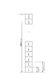
- FIG. 2 is a diagram illustrating a radio frame according to the first embodiment.
- FIG. 3 is a diagram illustrating radio resources according to the first embodiment.
- FIG. 4 is a diagram illustrating an application case according to the first embodiment.
- FIG. 5 is a diagram for explaining a retransmission control example 1 according to the first embodiment.
- FIG. 6 is a diagram for explaining a retransmission control example 2 according to the first embodiment.
- FIG. 7 is a diagram for explaining a retransmission control example 3 according to the first embodiment.
- FIG. 8 is a diagram for explaining a retransmission control example 4 according to the first embodiment.
- FIG. 9 is a diagram for explaining a retransmission control example 5 according to the first embodiment.
- FIG. 10 is a diagram for explaining reception resources according to the first embodiment.
- FIG. 11 is a diagram for explaining reception resources according to the first embodiment.
- FIG. 12 is a diagram illustrating the UE 10A (transmission side terminal) according to the first embodiment.
- FIG. 13 is a diagram illustrating the UE 10B (receiving side terminal) according to the first embodiment.
- FIG. 14 is a diagram illustrating the radio base station 310 according to the first embodiment.
- FIG. 15 is a diagram illustrating a mobile communication method according to the first embodiment.
- FIG. 16 is a diagram illustrating a mobile communication method according to the first embodiment.
- FIG. 15 is a diagram illustrating a mobile communication method according to the first embodiment.
- FIG. 17 is a diagram illustrating a control signal of the MAC layer according to the first embodiment.
- FIG. 18 is a diagram illustrating a control signal of the MAC layer according to the first embodiment.
- FIG. 19 is a diagram illustrating a control signal of the MAC layer according to the first embodiment.
- FIG. 20 is a diagram illustrating a mobile communication method according to the first modification.
- FIG. 21 is a diagram illustrating the mobile communication method according to the first modification.
- FIG. 22 is a diagram illustrating a MAC layer control signal according to the second modification.
- FIG. 23 is a diagram illustrating a control signal of the MAC layer according to the second modification.
- the mobile communication system directly communicates user data between a plurality of wireless terminals without using a wireless base station. Communication of user data directly performed between the plurality of wireless terminals is performed using some of the wireless resources allocated to the mobile communication system.
- the plurality of wireless terminals include a transmitting terminal that transmits the user data and a receiving terminal that receives the user data.
- the receiving terminal indicates whether or not the user data transmitted from the transmitting terminal can be received with respect to a connected wireless base station that establishes a wireless connection with the receiving terminal. Send a confirmation signal.
- the receiving terminal indicates to the connected wireless base station that establishes a wireless connection with the receiving terminal whether or not the user data transmitted from the transmitting terminal can be received.
- the connected radio base station knows the transport block size used for transmission of user data for communication directly without going through the radio base station, the user data is based on the delivery confirmation signal. It is possible to calculate the amount of data.
- D2D communication communication performed directly between a plurality of wireless terminals without going through a wireless base station.
- D2D communication a part of radio resources (D2D radio resources) among radio resources allocated to the mobile communication system is used.
- D2D radio resource for example, a part of the uplink radio resource is used.
- radio resources used for user data communication in D2D communication are allocated by a connected radio base station that establishes radio connections (RRC connections) with a plurality of radio terminals. .
- FIG. 1 is a diagram showing a mobile communication system 100 according to the first embodiment.
- the mobile communication system 100 includes a radio terminal 10 (hereinafter referred to as UE 10) and a core network 50.
- the mobile communication system 100 includes a first communication system and a second communication system.
- the first communication system is a communication system that supports, for example, LTE (Long Term Evolution).
- the first communication system includes, for example, a base station 110A (hereinafter, MeNB 110A), a home base station 110B (hereinafter, HeNB 110B), a home base station gateway 120B (hereinafter, HeNB-GW 120B), and an MME 130.
- MeNB 110A a base station 110A
- HeNB 110B home base station 110B
- HeNB-GW 120B home base station gateway 120B
- MME 130 Mobility Management Entity
- a radio access network (E-UTRAN; Evolved Universal Terrestrial Radio Access Network) corresponding to the first communication system is configured by MeNB 110A, HeNB 110B, and HeNB-GW 120B.
- the second communication system is a communication system compatible with, for example, UMTS (Universal Mobile Telecommunication System).
- the second communication system includes a base station 210A (hereinafter referred to as MNB 210A), a home base station 210B (hereinafter referred to as HNB 210B), an RNC 220A, a home base station gateway 220B (hereinafter referred to as HNB-GW 220B), and an SGSN 230.
- a radio access network (UTRAN: Universal Terrestrial Radio Access Network) corresponding to the second communication system is configured by MNB 210A, HNB 210B, RNC 220A, and HNB-GW 220B.
- the UE 10 is a device (User Equipment) configured to communicate with the second communication system or the first communication system.
- the UE 10 has a function of performing wireless communication with the MeNB 110A and the HeNB 110B.
- the UE 10 has a function of performing wireless communication with the MNB 210A and the HNB 210B.
- the MeNB 110A is a device (evolved NodeB) that manages the general cell 111A and performs radio communication with the UE 10 existing in the general cell 111A.
- the HeNB 110B is a device (Home evolved NodeB) that manages the specific cell 111B and performs radio communication with the UE 10 existing in the specific cell 111B.
- the HeNB-GW 120B is an apparatus (Home evolved NodeB Gateway) that is connected to the HeNB 110B and manages the HeNB 110B.
- the MME 130 is an apparatus (Mobility Management Entity) that manages the mobility of the UE 10 that is connected to the MeNB 110A and has established a wireless connection with the MeNB 110A. Further, the MME 130 is an apparatus that manages the mobility of the UE 10 that is connected to the HeNB 110B via the HeNB-GW 120B and has established a radio connection with the HeNB 110B.
- MME 130 Mobility Management Entity
- the MNB 210A is a device (NodeB) that manages the general cell 211A and performs radio communication with the UE 10 existing in the general cell 211A.
- the HNB 210B is a device (Home NodeB) that manages the specific cell 211B and performs radio communication with the UE 10 existing in the specific cell 211B.
- the RNC 220A is an apparatus (Radio Network Controller) that is connected to the MNB 210A and sets up a radio connection (RRC Connection) with the UE 10 existing in the general cell 211A.
- RRC Connection Radio Connection
- the HNB-GW 220B is a device (Home NodeB Gateway) that is connected to the HNB 210B and sets up a radio connection (RRC Connection) with the UE 10 existing in the specific cell 211B.
- RRC Connection Radio Connection
- SGSN 230 is a device (Serving GPRS Support Node) that performs packet switching in the packet switching domain.
- the SGSN 230 is provided in the core network 50.
- an apparatus MSC: Mobile Switching Center
- MSC Mobile Switching Center
- the general cell and the specific cell should be understood as a function of performing radio communication with the UE 10.
- the general cell and the specific cell are also used as terms indicating a cell coverage area.
- cells such as general cells and specific cells are identified by the frequency, spreading code, time slot, or the like used in the cells.
- the coverage area of general cells is wider than the coverage area of specific cells.
- the general cell is, for example, a macro cell provided by a telecommunications carrier.
- the specific cell is, for example, a femto cell or a home cell provided by a third party other than the communication carrier.
- the specific cell may be a CSG (Closed Subscriber Group) cell or a pico cell provided by a communication carrier.
- the first communication system will be mainly described. However, the following description may be applied to the second communication system.
- the OFDMA Orthogonal Frequency Division Multiple Access
- SC-FDMA Single-Carrier Frequency Multiplex
- a method is used.
- an uplink control channel (PUCCH: Physical Uplink Channel) and an uplink shared channel (PUSCH: Physical Uplink Channel) as uplink channels.
- PUSCH Physical Uplink Channel
- a downlink channel there are a downlink control channel (PDCCH; Physical Downlink Control Channel), a downlink shared channel (PDSCH; Physical Downlink Shared Channel), and the like.
- the uplink control channel is a channel that carries a control signal.
- the control signal includes, for example, CQI (Channel Quality Indicator), PMI (Precoding Matrix Indicator), RI (Rank Indicator), SR (Scheduling Request), ACK / NACK, and the like.
- CQI is a signal notifying the recommended modulation method and coding rate to be used for downlink transmission.
- PMI is a signal indicating a precoding matrix that is preferably used for downlink transmission.
- the RI is a signal indicating the number of layers (number of streams) to be used for downlink transmission.
- SR is a signal requesting allocation of uplink radio resources (resource blocks to be described later).
- ACK / NACK is a signal indicating whether or not a signal transmitted via a downlink channel (for example, PDSCH) has been received.
- the uplink shared channel is a channel that carries a control signal (including the control signal described above) and / or a data signal.
- the uplink radio resource may be allocated only to the data signal, or may be allocated so that the data signal and the control signal are multiplexed.
- the downlink control channel is a channel that carries a control signal.
- the control signals are, for example, Uplink SI (Scheduling Information), Downlink SI (Scheduling Information), and TPC bits.
- Uplink SI is a signal indicating uplink radio resource allocation.
- Downlink SI is a signal indicating downlink radio resource allocation.
- the TPC bit is a signal for instructing increase / decrease in power of a signal transmitted via an uplink channel.
- the downlink shared channel is a channel that carries control signals and / or data signals.
- the downlink radio resource may be allocated only to the data signal, or may be allocated so that the data signal and the control signal are multiplexed.
- TA Triming Advance
- TA is transmission timing correction information between UE10 and MeNB110A, and is measured by MeNB110A based on the uplink signal transmitted from UE10.
- ACK / NACK can be cited as a control signal transmitted via a channel other than the downlink control channel (PDCCH) and the downlink shared channel (PDSCH).
- ACK / NACK is a signal indicating whether or not a signal transmitted via an uplink channel (for example, PUSCH) has been received.
- the broadcast information is information such as MIB (Master Information Block) or SIB (System Information Block).
- the first communication system may include a relay node that relays data communication between the MeNB 110 ⁇ / b> A (or HeNB 110 ⁇ / b> B) and the UE 10.
- the second communication system may include a relay node that relays data communication with the MNB 210A (or HNB 210B).
- FIG. 2 is a diagram illustrating a radio frame in the first communication system.
- one radio frame is composed of 10 subframes, and one subframe is composed of two slots.
- the time length of one slot is 0.5 msec
- the time length of one subframe is 1 msec
- the time length of one radio frame is 10 msec.
- One slot is composed of a plurality of OFDM symbols (for example, 6 OFDM symbols or 7 OFDM symbols) in the downlink.
- one slot is configured by a plurality of SC-FDMA symbols (for example, six SC-FDMA symbols or seven SC-FDMA symbols) in the uplink.
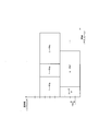
- FIG. 3 is a diagram illustrating radio resources in the first communication system.
- radio resources are defined by a frequency axis and a time axis.
- the frequency is composed of a plurality of subcarriers, and a predetermined number of subcarriers (12 subcarriers) are collectively referred to as a resource block (RB).
- RB resource block
- the time has units such as an OFDM symbol (or SC-FDMA symbol), a slot, a subframe, and a radio frame.
- radio resources can be allocated for each resource block. Also, it is possible to divide and allocate radio resources to a plurality of users (for example, user # 1 to user # 5) on the frequency axis and the time axis.
- the radio resource is allocated by the MeNB 110A.
- MeNB110A is allocated to each UE10 based on CQI, PMI, RI, etc.
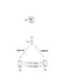
- FIG. 4 is a diagram for explaining an application case according to the first embodiment.
- UE10A and UE10B are shown as UE10.
- the radio base station 310 is preferably the MeNB 110A or the HeNB 110B.
- the radio base station 310 may be the MNB 210A or the HNB 210B.
- the radio base station 310 may be a relay node.
- the network device 330 is a device provided in the core network 50.
- the network device 330 may be the MME 130 or the SGSN 230.
- communication of user data (User-Plane data) between a plurality of wireless terminals is performed directly without going through a wireless base station (hereinafter referred to as D2D communication).
- communication of control data (C-Plane) data is performed via a radio base station as in the conventional mobile communication system.
- D2D communication is performed using a part of radio resources (hereinafter referred to as D2D radio resources) among radio resources allocated to the mobile communication system.
- D2D radio resources for example, a part of the uplink radio resource is used.
- radio resources used for user data communication in D2D communication are allocated by a connected radio base station (radio base station 310) that establishes a radio connection with a radio terminal (transmission side terminal or reception side terminal). Should.
- the D2D radio resource is preferably broadcast from each cell managed by the radio base station, for example.
- the D2D radio resource may be included in, for example, (Master Information Block) or SIB (System Information Block).
- FIG. 5 is a diagram for explaining retransmission control example 1 according to the first embodiment.
- UE10A and UE10B are shown as UE10.
- the UE 10A is an example of a transmission side terminal
- the UE 10B is an example of a reception side terminal.
- the UE 10B transmits a delivery confirmation signal (ACK / NACK) indicating whether or not the user data transmitted from the UE 10A has been received to the radio base station 310.
- the radio base station 310 transmits a delivery confirmation signal to the UE 10A in response to the delivery confirmation signal received from the UE 10B.
- the radio base station 310 may relay a delivery confirmation signal received from the UE 10B to the UE 10A.
- the radio base station 310 may transmit a delivery confirmation signal to the UE 10A together with a signal for allocating radio resources used for user data communication in the D2D communication to the UE 10A.
- UE10A retransmits user data to UE10B, when a delivery confirmation signal is NACK which shows that user data cannot be received.
- the retransmission control example 1 is a case where the UE 10A (transmission side terminal) performs the retransmission control.
- FIG. 6 is a diagram for explaining a retransmission control example 2 according to the first embodiment.
- UE10A and UE10B are shown as UE10.
- the UE 10A is an example of a transmission side terminal
- the UE 10B is an example of a reception side terminal.
- the UE 10B transmits a delivery confirmation signal (ACK / NACK) indicating whether or not the user data transmitted from the UE 10A has been received to the UE 10A.
- UE10A retransmits user data to UE10B, when a delivery confirmation signal is NACK which shows that user data cannot be received.
- the retransmission control example 2 is a case where the UE 10A (transmission side terminal) performs the retransmission control.
- FIG. 7 is a diagram for explaining a retransmission control example 3 according to the first embodiment.
- UE10A and UE10B are shown as UE10.
- the UE 10A is an example of a transmission side terminal
- the UE 10B is an example of a reception side terminal.
- the UE 10B transmits a delivery confirmation signal (ACK / NACK) indicating whether or not the user data transmitted from the UE 10A has been received to the UE 10A and the radio base station 310.
- the radio base station 310 transmits a delivery confirmation signal to the UE 10A in response to the delivery confirmation signal received from the UE 10B.
- the radio base station 310 may relay a delivery confirmation signal received from the UE 10B to the UE 10A.
- the radio base station 310 may transmit a delivery confirmation signal to the UE 10A together with a signal for allocating radio resources used for user data communication in the D2D communication to the UE 10A.
- the UE 10A performs user data retransmission control based on the delivery confirmation signal received from the UE 10B and the delivery confirmation signal received via the radio base station 310.
- the UE 10A when either one of the delivery confirmation signals received from the UE 10B and the radio base station 310 is NACK, the UE 10A retransmits the user data to the UE 10B.
- the UE 10A when the communication state of user data directly performed between the UE 10A and the UE 10B is good, the UE 10A does not refer to the delivery confirmation signal received via the radio base station 310, and from the UE 10B. You may refer to the delivery confirmation signal to receive.
- the UE 10A preferably notifies the radio base station 310 whether or not to refer to the delivery confirmation signal received via the radio base station 310.
- the radio base station 310 preferably omits transmission of the delivery confirmation signal to the UE 10A when notified that the delivery confirmation signal is not referred to.
- the UE 10B may omit transmission of a delivery confirmation signal to the radio base station 310 when the communication state of user data directly performed between the UE 10A and the UE 10B is good. In other words, the UE 10B transmits a delivery confirmation signal to the radio base station 310 when the communication state of user data directly performed between the UE 10A and the UE 10B is poor.
- the case where the communication state is good is a case where the transmission power used for user data communication is below the threshold, or a case where the modulation and coding scheme used for user data communication is above the threshold.
- the case where the communication state is good is a case where the block error rate is below the threshold, a case where the packet error rate is below the threshold, a case where QoS is satisfied, a case where the CQI is above the threshold,
- the case where the processing load of UE10A is less than a threshold value may be sufficient.
- the case where the communication state is inferior is a case where the transmission power used for user data communication is above the threshold, or a case where the modulation and coding scheme used for user data communication is below the threshold.
- the case where the communication state is poor is a case where the block error rate is above the threshold, a case where the packet error rate is above the threshold, a case where QoS is not satisfied, a case where the CQI is below the threshold, The case where the processing load of UE10A is over the threshold value may be sufficient.
- the retransmission control example 3 is a case where the UE 10A (transmission side terminal) performs the retransmission control.
- FIG. 8 is a diagram for explaining a retransmission control example 4 according to the first embodiment.
- UE10A and UE10B are shown as UE10.
- the UE 10A is an example of a transmission side terminal
- the UE 10B is an example of a reception side terminal.
- the UE 10B transmits a delivery confirmation signal (ACK / NACK) indicating whether or not the user data transmitted from the UE 10A has been received to the radio base station 310.
- the radio base station 310 allocates radio resources allocated to user data communication directly performed between the UE 10A and the UE 10B as reception resources for receiving user data. Thereby, the radio base station 310 can receive user data transmitted from the UE 10A to the UE 10B.
- the delivery confirmation signal is NACK indicating that the user data cannot be received
- the radio base station 310 retransmits the user data to the UE 10B.
- the retransmission control example 4 is a case where the radio base station 310 performs retransmission control.
- FIG. 9 is a diagram for explaining a retransmission control example 5 according to the first embodiment.
- UE10A and UE10B are shown as UE10.
- the UE 10A is an example of a transmission side terminal
- the UE 10B is an example of a reception side terminal.
- the UE 10B transmits a delivery confirmation signal (ACK / NACK) indicating whether or not the user data transmitted from the UE 10A has been received to the UE 10A.
- UE10A transmits the resending request
- the radio base station 310 allocates radio resources allocated to user data communication directly performed between the UE 10A and the UE 10B as reception resources for receiving user data. Thereby, the radio base station 310 can receive user data transmitted from the UE 10A to the UE 10B. When receiving the retransmission request, the radio base station 310 retransmits the user data to the UE 10B.
- the retransmission control example 5 is a case where the radio base station 310 performs retransmission control.
- the radio base station 310 can receive uplink user data from other UEs 10 using radio resources allocated to D2D communication.
- radio base station 310 when the radio resource allocated to D2D communication is allocated as a reception resource for receiving user data transmitted from UE 10A to UE 10B, radio base station 310 User data transmitted to the UE 10B can be received. In such a case, the radio base station 310 cannot receive uplink user data from other UEs 10 using radio resources allocated to D2D communication.
- FIG. 12 is a block diagram showing the UE 10A according to the first embodiment.
- the UE 10A includes a receiving unit 13A, a transmitting unit 14A, and a control unit 15A.
- the receiving unit 13A receives data from the radio base station 310 in cellular communication.
- the receiving unit 13A receives data from the UE 10B in the D2D communication.
- the reception unit 13A may receive a delivery confirmation signal (ACK / NACK) indicating whether or not user data has been received in the D2D communication from the UE 10B.
- the reception unit 13A may receive the delivery confirmation signal via the radio base station 310 in the D2D communication.
- the reception unit 13A acquires the target reception power of user data used in D2D communication from the radio base station 310 before the start of D2D communication.
- the target received power may be broadcast from the radio base station 310 using a broadcast channel such as SIB, or may be transmitted from the radio base station 310 using a dedicated control channel such as PDCCH.
- the target received power is also referred to as “D2D nominal power”.
- the target received power is preferably set according to the cell type (macro cell, pico cell, femto cell, CSG cell, etc.) managed by the radio base station 310.
- the target received power may be set according to the UE category of the UE 10A or the UE category of the UE 10B.
- the target received power may be set according to the subscriber contract of the UE 10A or the subscriber contract of the UE 10B.
- the target received power may be set according to the position of the UE 10A or the position of the UE 10B.
- the reception unit 13A obtains allocation information of radio resources used in D2D communication from the radio base station 310.
- the radio resource allocation information is existing uplink scheduling information (Uplink SI) used in cellular communication.
- Uplink scheduling information is transmitted from the radio base station 310 using a dedicated control channel such as PDCCH.
- the uplink scheduling information is also referred to as “Uplink Scheduling Grant”. However, it should be noted that the uplink scheduling information is expanded as shown below.
- the uplink scheduling information includes information indicating uplink radio resources allocated to the UE 10A, and a delivery confirmation signal indicating whether the user data transmitted from the UE 10A can be received via the radio base station 310. At least one of information indicating whether or not to be notified, information indicating a power control method used in D2D communication, and information indicating received power at which the UE 10B receives user data transmitted from the UE 10A Contains information.
- the information indicating the uplink radio resource allocated to the UE 10A includes information indicating an uplink resource block used in D2D communication, a transport format, information on HARQ (Hybrid Automatic Repeat Request), information on a spatial multiplexing method, and the like.
- the information indicating whether or not the delivery confirmation signal is notified via the radio base station 310 is based on whether the delivery confirmation signal (ACK / NACK) is notified from the UE 10B or the delivery confirmation signal (ACK / NACK) is transmitted to the radio base station. This is information indicating whether to be notified from the station 310.
- Information indicating the power control method used in the D2D communication includes an identifier for identifying a TPC (Transmission Power Control) bit used in the D2D communication, an increase step width of the transmission power that is increased in response to reception of the TPC bit (UP), and TPC It includes a step size for reducing the transmission power to be decreased in response to reception of the bit (DOWN).
- TPC Transmission Power Control
- the information indicating the reception power at which the UE 10B receives user data transmitted from the UE 10A is information indicating the reception power of the user data measured by the UE 10B.
- Information indicating the reception power of user data measured by the UE 10B is notified from the UE 10B to the UE 10A via the radio base station 310.
- the uplink scheduling information is preferably transmitted in a predetermined number (for example, four) of subframes before the subframe in which user data is transmitted in D2D communication, for example.
- the transmission unit 14A transmits data to the radio base station 310 in cellular communication.
- the transmitter 14A transmits data to the UE 10B in the D2D communication.
- the transmission unit 14A transmits user data to the UE 10B in D2D communication.
- the transmission unit 14A retransmits the user data to the UE 10B in response to the instruction output from the control unit 15A.
- the transmission unit 14A issues a user data retransmission request to the radio base station 310. May be sent to.
- the control unit 15A controls the UE 10A. Specifically, the control unit 15A controls D2D communication based on uplink scheduling information received from the radio base station 310. For example, the control unit 15A controls the transmission unit 14A to transmit user data to the UE 10B based on information indicating uplink radio resources to be allocated to the UE 10A. The control unit 15A controls the reception unit 13A to appropriately receive the delivery confirmation signal based on information indicating whether or not the delivery confirmation signal is notified via the radio base station 310. The control unit 15A receives the TPC bit from the radio base station 310 or the UE 10B based on the information indicating the power control method used in the D2D communication, and controls the transmission power of user data to be transmitted to the UE 10B. The control unit 15A calculates a path loss between the UE 10A and the UE 10B based on information indicating reception power received by the UE 10B from the user data transmitted from the UE 10A and the transmission power of the user data.
- control unit 15A determines whether to retransmit user data to the UE 10B based on a delivery confirmation signal received directly from the UE 10B or a delivery confirmation signal received via the radio base station 310. That is, the control unit 15A performs user data retransmission control. When it is determined that the user data is to be retransmitted, the control unit 15A instructs the transmission unit 14A to retransmit the user data.
- FIG. 13 is a block diagram showing the UE 10B according to the first embodiment.
- the UE 10B includes a reception unit 13B, a transmission unit 14B, and a control unit 15B.
- the receiving unit 13B receives data from the radio base station 310 in cellular communication.
- the receiving unit 13B receives data from the UE 10A in the D2D communication.
- the reception unit 13B receives user data (initial transmission) transmitted from the UE 10A in D2D communication.
- the reception unit 13B receives user data (retransmission) retransmitted from the UE 10A.
- the reception unit 13B acquires the target reception power of user data used in D2D communication from the radio base station 310 before the start of D2D communication.
- the target received power may be broadcast from the radio base station 310 using a broadcast channel such as SIB, or may be transmitted from the radio base station 310 using a dedicated control channel such as PDCCH.
- the target received power is also referred to as “D2D nominal power”.
- the reception unit 13B acquires, from the radio base station 310, radio resource allocation information used in D2D communication.
- the radio resource allocation information is D2D scheduling information different from existing uplink scheduling information (Uplink SI) used in cellular communication.
- Uplink SI uplink scheduling information
- the D2D scheduling information is scheduling information used in D2D communication.
- the D2D scheduling information is transmitted from the radio base station 310 using a dedicated control channel such as PDCCH.
- the D2D scheduling information is also referred to as “D2D scheduling Grants”.
- the D2D scheduling information includes information indicating that an uplink radio resource is used as a reception resource of D2D communication, an identifier of the UE 10A, information indicating an uplink radio resource allocated to the UE 10A, and user data transmitted from the UE 10A.
- Information indicating whether or not a delivery confirmation signal indicating whether or not reception is possible is notified via the radio base station 310, bandwidth and / or timing of uplink radio resources used as reception resources for D2D communication. At least one of the information requesting reception and the information indicating the power control method used in the D2D communication.
- the transmission unit 14B transmits data to the radio base station 310 in cellular communication.
- the transmitter 14A transmits data to the UE 10A in the D2D communication.
- the transmission unit 14B may transmit a delivery confirmation signal (ACK / NACK) indicating whether or not user data has been received to the UE 10A.
- the transmission unit 14B may transmit an acknowledgment signal (ACK / NACK) to the radio base station 310 in D2D communication.
- the delivery confirmation signal (ACK / NACK)
- a delivery confirmation signal included in the L1 / L2 layer control signal and a delivery confirmation signal (MAC Control Element) included in the MAC layer control signal can be considered.
- the MAC layer is a higher layer than L1 / L2.
- the delivery confirmation signal (ACK / NACK) is included in the control signal of the L1 / L2 layer
- the delivery confirmation signal is configured by a bit indicating whether or not the user data has been received, and the notification destination of the delivery confirmation signal
- the identifier of (UE10A) and the identifier of the notification source of the acknowledgment signal (UE10B) are not included.
- the control signal of the L1 / L2 layer it is possible to obtain the merits that there are few modifications to the existing system and the overhead accompanying transmission of the delivery confirmation signal is small.
- a rule is, for example, a rule in which a delivery confirmation signal is transmitted in a subframe after a predetermined number (for example, four) of subframes in which user data is transmitted in D2D communication.
- the identifier of the delivery confirmation signal notification destination (UE10A) and the notification source of the delivery confirmation signal (UE10B) ) Identifier may be included. This increases the overhead of the delivery confirmation signal, but can provide flexibility in function expansion. For example, it is possible to transmit a delivery confirmation signal for a plurality of communications (for example, cellular communications and D2D communications, two D2D communications) in one subframe.
- the control unit 15B controls the UE 10B. Specifically, the control unit 15B controls D2D communication based on D2D scheduling information received from the radio base station 310. For example, the control unit 15B controls the reception unit 13B to receive user data from the UE 10A based on information indicating uplink radio resources allocated to the UE 10A. The control unit 15B controls the transmission unit 14B to appropriately transmit the delivery confirmation signal based on the information indicating whether or not the delivery confirmation signal is notified via the radio base station 310. The control unit 15B transmits a TPC bit to the radio base station 310 or the UE 10A based on information indicating a power control method used in D2D communication.
- control unit 15B determines whether or not the user data transmitted from the UE 10A has been received, and instructs the transmission unit 14B to transmit a delivery confirmation signal. Specifically, the control unit 15B instructs the transmission unit 14B to transmit ACK when user data can be received. On the other hand, the control unit 15B instructs the transmission unit 14B to transmit NACK when the user data cannot be received.
- FIG. 14 is a block diagram showing the radio base station 310 according to the first embodiment.
- the radio base station 310 includes a reception unit 313, a transmission unit 314, and a control unit 315.
- the receiving unit 313 receives data from the UE 10. For example, the receiving unit 313 receives a delivery confirmation signal (ACK / NACK) indicating whether or not user data has been received in the D2D communication from the UE 10B. In addition, the reception unit 313 may receive user data transmitted from the UE 10A to the UE 10B.
- ACK / NACK delivery confirmation signal
- the transmission unit 314 transmits data to the UE 10. For example, in the D2D communication, the transmission unit 314 transmits a delivery confirmation signal to the UE 10A according to the delivery confirmation signal (ACK / NACK) received from the UE 10B. For example, the transmission unit 314 may relay a delivery confirmation signal received from the UE 10B to the UE 10A. Or the transmission part 314 may transmit a delivery confirmation signal to UE10A with the signal (Uplink scheduling grants) which allocates the radio
- the delivery confirmation signal ACK / NACK
- the transmission unit 314 may relay a delivery confirmation signal received from the UE 10B to the UE 10A.
- the transmission part 314 may transmit a delivery confirmation signal to UE10A with the signal (Uplink scheduling grants) which allocates the radio
- the transmission unit 314 includes information indicating whether the radio resource is allocated to initial transmission or retransmission in a signal (Uplink scheduling grants) that allocates radio resources used for user data communication in the D2D communication to the UE 10A. Also good. Or the transmission part 314 may transmit a delivery confirmation signal to UE10A using "Uplink Scheduling Grants" different from PDCCH, such as PHICH (Physical Hybrid-ARQ Indicator Channel).
- PDCCH Physical Hybrid-ARQ Indicator Channel
- the transmission unit 314 retransmits the user data to the UE 10B.
- the transmission part 314 resends user data to UE10B, when a retransmission request is received from UE10A in D2D communication.
- the transmission unit 314 notifies the UE 10A and the UE 10B of the target received power of user data used in the D2D communication before the start of the D2D communication.
- the transmission unit 314 may broadcast the target reception power using a broadcast channel such as SIB, and may transmit the target reception power to the UE 10A and the UE 10B using a dedicated control channel such as PDCCH.
- the target received power is also referred to as “D2D nominal power”.
- the transmission unit 314 notifies the UE 10A of allocation information of radio resources used in D2D communication.
- the radio resource allocation information is existing uplink scheduling information (Uplink SI) used in cellular communication.
- the transmission unit 314 transmits uplink scheduling information to the UE 10A using a dedicated control channel such as PDCCH.
- the uplink scheduling information is also referred to as “Uplink Scheduling Grant”. However, it should be noted that the uplink scheduling information is expanded as shown below.
- the uplink scheduling information includes information indicating uplink radio resources allocated to the UE 10A, and a delivery confirmation signal indicating whether or not the user data transmitted from the UE 10A has been received.
- the information indicating whether to be notified via the base station 310, the information indicating the power control method used in the D2D communication, and the information indicating the reception power received by the UE 10B user data transmitted from the UE 10A At least one piece of information is included.
- the transmission unit 314 notifies the UE 10B of allocation information of radio resources used in D2D communication.
- the radio resource allocation information is D2D scheduling information different from existing uplink scheduling information (Uplink SI) used in cellular communication. It should be noted that the D2D scheduling information is scheduling information used in D2D communication.
- the transmission unit 314 transmits D2D scheduling information to the UE 10B using a dedicated control channel such as PDCCH.
- the D2D scheduling information is also referred to as “D2D scheduling Grants”.
- the D2D scheduling information includes information indicating that an uplink radio resource is used as a reception resource of D2D communication, an identifier of the UE 10A, information indicating an uplink radio resource allocated to the UE 10A, and user data transmitted from the UE 10A.
- Information indicating whether or not a delivery confirmation signal indicating whether or not reception is possible is notified via the radio base station 310, bandwidth and / or timing of uplink radio resources used as reception resources for D2D communication. At least one of the information requesting reception and the information indicating the power control method used in the D2D communication.
- the control unit 315 controls the radio base station 310. Specifically, the control unit 315 allocates uplink and downlink radio resources to the UE 10. Here, the control unit 315 may allocate uplink radio resources as radio resources used in D2D communication. That is, the control unit 315 may allocate uplink radio resources as reception resources for receiving user data.
- the control unit 315 when the radio resource used in the D2D communication is allocated to the UE 10, the control unit 315 stores radio resource allocation information ("Uplink Scheduling Grant"). In particular, the control unit 315 stores the transport block size used in the D2D communication included in the radio resource allocation information. The control unit 315 calculates the data amount of user data in D2D communication based on the delivery confirmation signal and the radio resource allocation information.
- control unit 315 may control the transmission unit 314 to notify the network device 330 (upper node) of the calculated amount of user data. Further, the control unit 315 may control the transmission unit 314 so as to notify the network device 330 (upper node) of the identifier of the UE 10A and the identifier of the UE 10B together with the calculated amount of user data.
- 15 to 16 are diagrams showing a mobile communication method according to the first embodiment.
- the delivery confirmation signal (ACK / NACK) is included in the control signal of the L1 / L2 layer will be described with reference to FIG.
- the radio base station 310 transmits uplink scheduling information (“Uplink scheduling grants”) to the UE 10A.
- the radio base station 310 transmits D2D scheduling information (“D2D scheduling grants”) to the UE 10B.
- the radio base station 310 may collectively allocate radio resources to the UE 10A and the UE 10B with one control signal by using the RNTI common to the UE 10A and the UE 10B.
- Uplink scheduling grants is information obtained by expanding and diverting uplink scheduling information used in cellular communication.
- D2D scheduling grants is information defined separately from “Uplink scheduling grants”.
- Uplink scheduling grants” and “D2D scheduling grants” are transmitted using an individual control channel such as PDCCH, for example.
- Step 20 the UE 10A transmits user data directly to the UE 10B without going through the radio base station 310 based on the uplink scheduling information received from the radio base station 310.
- the UE 10B directly receives user data from the UE 10A without going through the radio base station 310 based on the D2D scheduling information.
- the radio base station 310 stores uplink scheduling information ("Uplink scheduling grants"). In particular, the radio base station 310 stores the transport block size.
- the UE 10B transmits a delivery confirmation signal (ACK / NACK) to the radio base station 310.
- UE 10B transmits an arrival confirmation signal (ACK / NACK) to radio base station 310 according to a predetermined rule.
- a rule is, for example, a rule in which a delivery confirmation signal is transmitted in a subframe after a predetermined number (for example, four) of subframes in which user data is transmitted in D2D communication.
- the radio base station 310 transmits an acknowledgment signal (ACK / NACK) to the UE 10A.
- the radio base station 310 transmits an arrival confirmation signal (ACK / NACK) to the UE 10A according to a predetermined rule.
- a rule is, for example, a rule in which a delivery confirmation signal is transmitted in a subframe after a predetermined number (for example, 8) of subframes in which user data is transmitted by D2D communication.
- Step 60 the radio base station 310 reads the uplink scheduling information (“Uplink scheduling grants”) stored in Step 30.
- the radio base station 310 reads the transport block size.
- the radio base station 310 calculates the data amount of user data in the D2D communication based on the scheduling information and the delivery confirmation signal.
- the radio base station 310 gives the identifier of the user data transmission source (UE 10A) and the identifier of the user data transmission destination (UE 10B) to the calculated data amount of the user data.
- the radio base station 310 notifies the network device 330 (upper node) of the identifier of the UE 10A and the identifier of the UE 10B together with the calculated amount of user data.
- the UE 10A is a transmission source of user data and a notification destination of a delivery confirmation signal.
- the UE 10B is a transmission destination of user data and a notification source of a delivery confirmation signal.
- the UE 10B transmits a delivery confirmation signal (ACK / NACK) to the radio base station 310.
- the UE 10B transmits, together with the delivery confirmation signal, the identifier of the transmission confirmation signal transmission source (UE 10B) and the notification destination of the delivery confirmation signal (UE 10A) to the radio base station 310.
- the radio base station 310 confirms the transmission source (UE 10B) of the delivery confirmation signal. That is, the radio base station 310 confirms the transmission destination (UE 10B) of user data.
- step 44A the notification destination (UE10A) of the delivery confirmation signal is confirmed. That is, the radio base station 310 confirms the user data transmission source (UE 10A).
- the radio base station 310 transmits an arrival confirmation signal (ACK / NACK) to the UE 10A.
- the radio base station 310 transmits, together with the delivery confirmation signal, the identifier of the transmission confirmation signal transmission source (UE 10B) to the UE 10A.
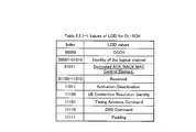
- the delivery confirmation signal (ACK / NACK) is included in the “MAC Control Element” that constitutes the payload of the control signal of the MAC layer, for example, as shown in FIG. Bits reserved for future expansion can be used to represent acknowledgment signals used in D2D communications.
- the delivery confirmation signal used in the D2D communication is included in the payload by the extension of “R / R / E / LCID Sub-header” constituting the header of the control signal of the MAC layer.
- the extension of “R / R / E / LCID Sub-header” constituting the header of the control signal of the MAC layer.
- the UE 10B receives user data transmitted from the UE 10A (transmitting terminal) to the connected radio base station 310 that establishes a radio connection with the UE 10B.
- a delivery confirmation signal indicating whether or not it has been made is transmitted.
- the connected radio base station 310 knows the transport block size used in the D2D communication, it is possible to calculate the data amount of the user data based on the delivery confirmation signal.
- the UE 10A may receive the delivery confirmation signal from the UE 10B without going through the radio base station 310.
- step 40B the UE 10A receives the delivery confirmation signal transmitted from the UE 10B at the same timing as the radio base station 310.
- the process of step 50 may be omitted.
- Step 40C the UE 10A receives the delivery confirmation signal transmitted from the UE 10B at the same timing as the radio base station 310. In the case shown in FIG. 21, the process of step 50A may be omitted.
- the UE 10A receives the delivery confirmation signal transmitted from the UE 10B at the same timing as that of the radio base station 310. Therefore, it is possible to perform retransmission control of user data promptly.
- Modification Example 2 of the first embodiment will be described.
- MAC Control Element illustrated in FIG. 17
- ACK / NACK acknowledgment signals
- a field (Number) indicating the number of acknowledgment signals (ACK / NACK) to be transmitted by one “MAC Control Element” using bits reserved for future expansion. of ACK / NACK) may be added.
- the case where two UEs 10 perform communication in D2D communication is illustrated.
- the embodiment is not limited to this.
- three or more UEs 10 may perform communication.
- the radio resource used in the D2D communication is an uplink radio resource.
- the embodiment is not limited to this.
- the radio resource used in D2D communication may be a downlink radio resource.
- the radio base station 310 calculates the data amount of user data in D2D communication.
- the UE 10A transmission side terminal
- the UE 10A may calculate the amount of user data in D2D communication.
- the UE 10A preferably notifies the radio base station 310 of the calculated amount of user data.
- the UE 10A may notify the radio base station 310 of the identifier of the UE 10A and the identifier of the UE 10B together with the calculated data amount of the user data, together with the calculated data amount of the user data.
- a program for causing a computer to execute each process performed by the UE 10 may be provided.
- the program may be recorded on a computer readable medium. If a computer-readable medium is used, a program can be installed in the computer.
- the computer-readable medium on which the program is recorded may be a non-transitory recording medium.
- the non-transitory recording medium is not particularly limited, but may be a recording medium such as a CD-ROM or a DVD-ROM.
- a chip configured by a memory that stores a program for executing each process performed by the UE 10 (UE 10A or UE 10B) and a processor that executes the program stored in the memory may be provided.
- the present invention it is possible to calculate the amount of user data based on the delivery confirmation signal.
Abstract
Description
実施形態に係る移動通信システムは、複数の無線端末の間でユーザデータの通信を、無線基地局を介さずに直接的に行う。前記複数の無線端末の間で直接的に行われるユーザデータの通信は、移動通信システムに割り当てられた無線リソースのうち、一部の無線リソースを用いて行われている。前記複数の無線端末は、前記ユーザデータを送信する送信側端末と、前記ユーザデータを受信する受信側端末とを含む。前記受信側端末は、前記受信側端末と無線接続を確立するコネクティッド状態の無線基地局に対して、前記送信側端末から送信された前記ユーザデータを受信することができたか否かを示す送達確認信号を送信する。
(移動通信システム)
以下において、第1実施形態に係る移動通信システムについて説明する。図1は、第1実施形態に係る移動通信システム100を示す図である。
以下において、第1通信システムにおける無線フレームについて説明する。図2は、第1通信システムにおける無線フレームを示す図である。
以下において、第1通信システムにおける無線リソースについて説明する。図3は、第1通信システムにおける無線リソースを示す図である。
以下において、第1実施形態に係る適用ケースについて説明する。図4は、第1実施形態に係る適用ケースについて説明するための図である。図4では、UE10として、UE10A及びUE10Bが示されている。無線基地局310は、MeNB110A又はHeNB110Bであることが好ましい。但し、無線基地局310は、MNB210A又はHNB210Bであってもよい。或いは、無線基地局310は、リレーノードであってもよい。ネットワーク装置330は、コアネットワーク50に設けられる装置である。ネットワーク装置330は、MME130であってもよく、SGSN230であってもよい。
以下において、第1実施形態に係る再送制御例1について説明する。図5は、第1実施形態に係る再送制御例1について説明するための図である。図5では、UE10として、UE10A及びUE10Bが示されている。UE10Aは、送信側端末の一例であり、UE10Bは、受信側端末の一例である。
以下において、第1実施形態に係る再送制御例2について説明する。図6は、第1実施形態に係る再送制御例2について説明するための図である。図6では、UE10として、UE10A及びUE10Bが示されている。UE10Aは、送信側端末の一例であり、UE10Bは、受信側端末の一例である。
以下において、第1実施形態に係る再送制御例3について説明する。図7は、第1実施形態に係る再送制御例3について説明するための図である。図7では、UE10として、UE10A及びUE10Bが示されている。UE10Aは、送信側端末の一例であり、UE10Bは、受信側端末の一例である。
以下において、第1実施形態に係る再送制御例4について説明する。図8は、第1実施形態に係る再送制御例4について説明するための図である。図8では、UE10として、UE10A及びUE10Bが示されている。UE10Aは、送信側端末の一例であり、UE10Bは、受信側端末の一例である。
以下において、第1実施形態に係る再送制御例5について説明する。図9は、第1実施形態に係る再送制御例5について説明するための図である。図9では、UE10として、UE10A及びUE10Bが示されている。UE10Aは、送信側端末の一例であり、UE10Bは、受信側端末の一例である。
以下において、第1実施形態に係る受信リソースについて説明する。図10及び図11は、第1実施形態に係る受信リソースを説明するための図である。
以下において、第1実施形態に係る送信側端末について説明する。ここでは、送信側端末として、UE10Aを例示する。図12は、第1実施形態に係るUE10Aを示すブロック図である。
以下において、第1実施形態に係る受信側端末について説明する。ここでは、受信側端末として、UE10Bを例示する。図13は、第1実施形態に係るUE10Bを示すブロック図である。
以下において、第1実施形態に係る無線基地局について説明する。図14は、第1実施形態に係る無線基地局310を示すブロック図である。
以下において、第1実施形態に係る移動通信方法について説明する。図15~図16は、第1実施形態に係る移動通信方法を示す図である。
第1実施形態では、UE10B(受信側端末)は、UE10Bと無線接続を確立するコネクティッド状態の無線基地局310に対して、UE10A(送信側端末)から送信されたユーザデータを受信することができたか否かを示す送達確認信号を送信する。ここで、コネクティッド状態の無線基地局310は、D2D通信で用いるトランスポートブロックサイズを知っているため、送達確認信号に基づいて、ユーザデータのデータ量を算出することが可能である。
以下において、第1実施形態の変更例1について説明する。第1実施形態では詳述していないが、変更例1では、UE10Aは、無線基地局310を経由せずに、送達確認信号をUE10Bから受信してもよい。
以下において、第1実施形態の変更例2について説明する。変更例2では、図17に示す“MAC Control Element”の変更例について説明する。
本発明は上述した実施形態によって説明したが、この開示の一部をなす論述及び図面は、この発明を限定するものであると理解すべきではない。この開示から当業者には様々な代替実施形態、実施例及び運用技術が明らかとなろう。
Claims (9)
- 複数の無線端末の間でユーザデータの通信を、無線基地局を介さずに直接的に行う移動通信システムであって、
前記複数の無線端末の間で直接的に行われるユーザデータの通信は、移動通信システムに割り当てられた無線リソースのうち、一部の無線リソースを用いて行われており、
前記複数の無線端末は、前記ユーザデータを送信する送信側端末と、前記ユーザデータを受信する受信側端末とを含み、
前記受信側端末は、前記受信側端末と無線接続を確立するコネクティッド状態の無線基地局に対して、前記送信側端末から送信された前記ユーザデータを受信することができたか否かを示す送達確認信号を送信することを特徴とする移動通信システム。 - 前記コネクティッド状態の無線基地局は、前記送信側端末に対して、前記送信側端末から送信された前記ユーザデータを受信することができたか否かを通知することを特徴とする請求項1に記載の移動通信システム。
- 前記送達確認信号は、前記送信側端末の識別子を含むことを特徴とする請求項1に記載の移動通信システム。
- 前記送達確認信号は、前記受信側端末の識別子を含むことを特徴とする請求項1に記載の移動通信システム。
- 前記コネクティッド状態の無線基地局は、前記送信側端末に対して、前記コネクティッド状態の無線基地局を介さずに直接的に行う通信で用いる無線リソースの割当情報を送信し、
前記コネクティッド状態の無線基地局は、前記送達確認信号及び前記無線リソースの割当情報に基づいて、前記コネクティッド状態の無線基地局を介さずに直接的に行う通信における前記ユーザデータのデータ量を算出することを特徴とする請求項1に記載の移動通信システム。 - 前記コネクティッド状態の無線基地局は、前記無線基地局よりも上位のノードに対して、算出されたユーザデータのデータ量を通知することを特徴とする請求項5に記載の移動通信システム。
- 前記コネクティッド状態の無線基地局は、前記無線基地局よりも上位のノードに対して、算出されたユーザデータのデータ量とともに、前記送信側端末の識別子及び前記受信側端末の識別子を通知することを特徴とする請求項6に記載の移動通信システム。
- 前記送信側端末は、前記コネクティッド状態の無線基地局に対して送信された前記送達確認信号を受信することを特徴とする請求項1に記載の移動通信システム。
- 複数の無線端末の間でユーザデータの通信を、無線基地局を介さずに直接的に行う移動通信システムで用いる移動通信方法であって、
前記複数の無線端末の間で直接的に行われるユーザデータの通信は、移動通信システムに割り当てられた無線リソースのうち、一部の無線リソースを用いて行われており、
前記複数の無線端末は、前記ユーザデータを送信する送信側端末と、前記ユーザデータを受信する受信側端末とを含み、
前記受信側端末から、前記受信側端末と無線接続を確立するコネクティッド状態の無線基地局に対して、前記送信側端末から送信された前記ユーザデータを受信することができたか否かを示す送達確認信号を送信するステップを備えることを特徴とする移動通信方法。
Priority Applications (4)
| Application Number | Priority Date | Filing Date | Title |
|---|---|---|---|
| EP13823338.2A EP2879462A4 (en) | 2012-07-27 | 2013-07-23 | MOBILE COMMUNICATION SYSTEM AND MOBILE COMMUNICATION METHOD APPLIED IN THE MOBILE COMMUNICATION SYSTEM |
| JP2014526949A JP6001663B2 (ja) | 2012-07-27 | 2013-07-23 | 移動通信システム、移動通信方法及び無線基地局 |
| US14/416,132 US9515801B2 (en) | 2012-07-27 | 2013-07-23 | Mobile communication system and mobile communication method used in a mobile communication system |
| US15/336,507 US9973317B2 (en) | 2012-07-27 | 2016-10-27 | Mobile communication system and mobile communication method used in a mobile communication system |
Applications Claiming Priority (2)
| Application Number | Priority Date | Filing Date | Title |
|---|---|---|---|
| US201261676785P | 2012-07-27 | 2012-07-27 | |
| US61/676,785 | 2012-07-27 |
Related Child Applications (2)
| Application Number | Title | Priority Date | Filing Date |
|---|---|---|---|
| US14/416,132 A-371-Of-International US9515801B2 (en) | 2012-07-27 | 2013-07-23 | Mobile communication system and mobile communication method used in a mobile communication system |
| US15/336,507 Continuation US9973317B2 (en) | 2012-07-27 | 2016-10-27 | Mobile communication system and mobile communication method used in a mobile communication system |
Publications (1)
| Publication Number | Publication Date |
|---|---|
| WO2014017503A1 true WO2014017503A1 (ja) | 2014-01-30 |
Family
ID=49997312
Family Applications (1)
| Application Number | Title | Priority Date | Filing Date |
|---|---|---|---|
| PCT/JP2013/069955 WO2014017503A1 (ja) | 2012-07-27 | 2013-07-23 | 移動通信システム、移動通信システムで用いる移動通信方法 |
Country Status (4)
| Country | Link |
|---|---|
| US (2) | US9515801B2 (ja) |
| EP (1) | EP2879462A4 (ja) |
| JP (2) | JP6001663B2 (ja) |
| WO (1) | WO2014017503A1 (ja) |
Cited By (2)
| Publication number | Priority date | Publication date | Assignee | Title |
|---|---|---|---|---|
| WO2016063599A1 (ja) * | 2014-10-24 | 2016-04-28 | シャープ株式会社 | 端末装置、集積回路、および、通信方法 |
| WO2020144787A1 (ja) * | 2019-01-09 | 2020-07-16 | 株式会社Nttドコモ | ユーザ装置、及びフィードバック情報送信方法 |
Families Citing this family (7)
| Publication number | Priority date | Publication date | Assignee | Title |
|---|---|---|---|---|
| US9578666B2 (en) | 2012-09-27 | 2017-02-21 | Kyocera Corporation | User terminal for D2D communication using uplink radio resource |
| US10172098B2 (en) * | 2014-05-29 | 2019-01-01 | Telefonaktiebolaget L M Ericsson (Publ) | Power control for mitigating device-to-device interference to adjacent networks |
| US11089490B1 (en) * | 2015-03-27 | 2021-08-10 | M87, Inc. | Methods and apparatus for collecting and/or using wireless communication related information to facilitate WT mode of operation decisions |
| US11115789B2 (en) * | 2016-11-04 | 2021-09-07 | Lg Electronics Inc. | Resource allocation method for V2X communication in wireless communication system and apparatus therefor |
| JP7263311B2 (ja) | 2017-07-21 | 2023-04-24 | エルジー エレクトロニクス インコーポレイティド | 無線通信システムにおいて他の端末から信号を受信した端末がフィードバックを送信する方法及び装置 |
| US11496246B2 (en) * | 2019-01-10 | 2022-11-08 | Samsung Electronics Co., Ltd. | HARQ operation and power control in sidelink |
| US11848787B2 (en) * | 2020-01-02 | 2023-12-19 | Qualcomm Incorporated | Multiplexed communication for a base station and a programmable logic controller |
Citations (3)
| Publication number | Priority date | Publication date | Assignee | Title |
|---|---|---|---|---|
| WO2009133740A1 (ja) * | 2008-04-30 | 2009-11-05 | 三菱電機株式会社 | 車載通信装置および路車間-車々間通信連携システム |
| JP2011120049A (ja) * | 2009-12-04 | 2011-06-16 | Fujitsu Ltd | 移動端末、基地局、通信システムおよび通信方法 |
| JP2012244367A (ja) * | 2011-05-18 | 2012-12-10 | Ntt Docomo Inc | 移動通信方法 |
Family Cites Families (11)
| Publication number | Priority date | Publication date | Assignee | Title |
|---|---|---|---|---|
| JPH1198570A (ja) * | 1997-09-22 | 1999-04-09 | Sanyo Electric Co Ltd | 携帯電話機 |
| WO2008023781A1 (fr) | 2006-08-24 | 2008-02-28 | Panasonic Corporation | Système de communication, procédé de communication, terminal radio, dispositif de relais radio, et dispositif de commande |
| KR101367798B1 (ko) * | 2007-06-29 | 2014-02-28 | 삼성전자주식회사 | 광대역 무선통신 시스템에서 피투피 통신 설정 장치 및방법 |
| US8634763B2 (en) * | 2008-04-22 | 2014-01-21 | Intel Corporation | Cooperative communications techniques |
| JPWO2009150853A1 (ja) * | 2008-06-13 | 2011-11-10 | パナソニック株式会社 | 中継局装置、無線通信装置、バッファクリア方法および信号中継方法 |
| WO2010050531A1 (ja) | 2008-10-28 | 2010-05-06 | アイコム株式会社 | 無線端末装置、無線通信方法、無線通信システム及びプログラム |
| US8458353B2 (en) * | 2009-08-13 | 2013-06-04 | Qualcomm Incorporated | Method and apparatus for link aggregation in a heterogeneous communication system |
| US8666403B2 (en) * | 2009-10-23 | 2014-03-04 | Nokia Solutions And Networks Oy | Systems, methods, and apparatuses for facilitating device-to-device connection establishment |
| EP2543212B1 (en) * | 2010-03-05 | 2016-03-02 | Nokia Technologies Oy | Handover of direct peer to peer communication |
| US8744458B2 (en) * | 2010-11-19 | 2014-06-03 | Nokia Corporation | Signaling mixed resource allocations for D2D communications |
| KR20120074251A (ko) * | 2010-12-27 | 2012-07-05 | 한국전자통신연구원 | 단말간 직접 연결 통신 및 단말 릴레잉을 위한 디바이스 대 디바이스 링크의 harq 및 적응 전송 방법 |
-
2013
- 2013-07-23 WO PCT/JP2013/069955 patent/WO2014017503A1/ja active Application Filing
- 2013-07-23 EP EP13823338.2A patent/EP2879462A4/en not_active Withdrawn
- 2013-07-23 JP JP2014526949A patent/JP6001663B2/ja active Active
- 2013-07-23 US US14/416,132 patent/US9515801B2/en active Active
-
2016
- 2016-09-01 JP JP2016170709A patent/JP6305481B2/ja active Active
- 2016-10-27 US US15/336,507 patent/US9973317B2/en active Active
Patent Citations (3)
| Publication number | Priority date | Publication date | Assignee | Title |
|---|---|---|---|---|
| WO2009133740A1 (ja) * | 2008-04-30 | 2009-11-05 | 三菱電機株式会社 | 車載通信装置および路車間-車々間通信連携システム |
| JP2011120049A (ja) * | 2009-12-04 | 2011-06-16 | Fujitsu Ltd | 移動端末、基地局、通信システムおよび通信方法 |
| JP2012244367A (ja) * | 2011-05-18 | 2012-12-10 | Ntt Docomo Inc | 移動通信方法 |
Non-Patent Citations (1)
| Title |
|---|
| See also references of EP2879462A4 * |
Cited By (2)
| Publication number | Priority date | Publication date | Assignee | Title |
|---|---|---|---|---|
| WO2016063599A1 (ja) * | 2014-10-24 | 2016-04-28 | シャープ株式会社 | 端末装置、集積回路、および、通信方法 |
| WO2020144787A1 (ja) * | 2019-01-09 | 2020-07-16 | 株式会社Nttドコモ | ユーザ装置、及びフィードバック情報送信方法 |
Also Published As
| Publication number | Publication date |
|---|---|
| JP6001663B2 (ja) | 2016-10-05 |
| EP2879462A4 (en) | 2016-05-04 |
| US20170048050A1 (en) | 2017-02-16 |
| JP6305481B2 (ja) | 2018-04-04 |
| US20150180635A1 (en) | 2015-06-25 |
| US9973317B2 (en) | 2018-05-15 |
| EP2879462A1 (en) | 2015-06-03 |
| JPWO2014017503A1 (ja) | 2016-07-11 |
| JP2016226039A (ja) | 2016-12-28 |
| US9515801B2 (en) | 2016-12-06 |
Similar Documents
| Publication | Publication Date | Title |
|---|---|---|
| JP6305481B2 (ja) | 無線端末、プロセッサ及び基地局 | |
| US10321465B2 (en) | Mobile communication system and mobile communication method | |
| JP6169743B2 (ja) | 無線端末、プロセッサ、基地局及び移動通信方法 | |
| JP6285480B2 (ja) | 無線端末、プロセッサ、無線基地局、及び移動通信方法 | |
| JP6017558B2 (ja) | 移動通信システム、移動通信方法及び無線基地局 | |
| JP5869692B2 (ja) | 移動通信システム、無線端末及び移動通信方法 | |
| JP2017188931A (ja) | 移動通信システム、ユーザ端末、及びプロセッサ | |
| JP5755798B2 (ja) | 移動通信システム及び移動通信方法 | |
| WO2013129419A1 (ja) | 移動通信システム、移動通信方法、無線基地局及び無線端末 |
Legal Events
| Date | Code | Title | Description |
|---|---|---|---|
| 121 | Ep: the epo has been informed by wipo that ep was designated in this application |
Ref document number: 13823338 Country of ref document: EP Kind code of ref document: A1 |
|
| ENP | Entry into the national phase |
Ref document number: 2014526949 Country of ref document: JP Kind code of ref document: A |
|
| WWE | Wipo information: entry into national phase |
Ref document number: 14416132 Country of ref document: US |
|
| NENP | Non-entry into the national phase |
Ref country code: DE |
|
| WWE | Wipo information: entry into national phase |
Ref document number: 2013823338 Country of ref document: EP |