WO2014017492A1 - 建設機械の制御システム - Google Patents
建設機械の制御システム Download PDFInfo
- Publication number
- WO2014017492A1 WO2014017492A1 PCT/JP2013/069930 JP2013069930W WO2014017492A1 WO 2014017492 A1 WO2014017492 A1 WO 2014017492A1 JP 2013069930 W JP2013069930 W JP 2013069930W WO 2014017492 A1 WO2014017492 A1 WO 2014017492A1
- Authority
- WO
- WIPO (PCT)
- Prior art keywords
- side chamber
- valve
- piston
- pilot
- construction machine
- Prior art date
- Legal status (The legal status is an assumption and is not a legal conclusion. Google has not performed a legal analysis and makes no representation as to the accuracy of the status listed.)
- Ceased
Links
Images

Classifications
-
- F—MECHANICAL ENGINEERING; LIGHTING; HEATING; WEAPONS; BLASTING
- F15—FLUID-PRESSURE ACTUATORS; HYDRAULICS OR PNEUMATICS IN GENERAL
- F15B—SYSTEMS ACTING BY MEANS OF FLUIDS IN GENERAL; FLUID-PRESSURE ACTUATORS, e.g. SERVOMOTORS; DETAILS OF FLUID-PRESSURE SYSTEMS, NOT OTHERWISE PROVIDED FOR
- F15B21/00—Common features of fluid actuator systems; Fluid-pressure actuator systems or details thereof, not covered by any other group of this subclass
- F15B21/14—Energy-recuperation means
-
- E—FIXED CONSTRUCTIONS
- E02—HYDRAULIC ENGINEERING; FOUNDATIONS; SOIL SHIFTING
- E02F—DREDGING; SOIL-SHIFTING
- E02F9/00—Component parts of dredgers or soil-shifting machines, not restricted to one of the kinds covered by groups E02F3/00 - E02F7/00
- E02F9/20—Drives; Control devices
-
- E—FIXED CONSTRUCTIONS
- E02—HYDRAULIC ENGINEERING; FOUNDATIONS; SOIL SHIFTING
- E02F—DREDGING; SOIL-SHIFTING
- E02F9/00—Component parts of dredgers or soil-shifting machines, not restricted to one of the kinds covered by groups E02F3/00 - E02F7/00
- E02F9/20—Drives; Control devices
- E02F9/2058—Electric or electro-mechanical or mechanical control devices of vehicle sub-units
- E02F9/2095—Control of electric, electro-mechanical or mechanical equipment not otherwise provided for, e.g. ventilators, electro-driven fans
-
- E—FIXED CONSTRUCTIONS
- E02—HYDRAULIC ENGINEERING; FOUNDATIONS; SOIL SHIFTING
- E02F—DREDGING; SOIL-SHIFTING
- E02F9/00—Component parts of dredgers or soil-shifting machines, not restricted to one of the kinds covered by groups E02F3/00 - E02F7/00
- E02F9/20—Drives; Control devices
- E02F9/22—Hydraulic or pneumatic drives
- E02F9/2217—Hydraulic or pneumatic drives with energy recovery arrangements, e.g. using accumulators, flywheels
-
- E—FIXED CONSTRUCTIONS
- E02—HYDRAULIC ENGINEERING; FOUNDATIONS; SOIL SHIFTING
- E02F—DREDGING; SOIL-SHIFTING
- E02F9/00—Component parts of dredgers or soil-shifting machines, not restricted to one of the kinds covered by groups E02F3/00 - E02F7/00
- E02F9/20—Drives; Control devices
- E02F9/22—Hydraulic or pneumatic drives
- E02F9/2278—Hydraulic circuits
- E02F9/2285—Pilot-operated systems
-
- E—FIXED CONSTRUCTIONS
- E02—HYDRAULIC ENGINEERING; FOUNDATIONS; SOIL SHIFTING
- E02F—DREDGING; SOIL-SHIFTING
- E02F9/00—Component parts of dredgers or soil-shifting machines, not restricted to one of the kinds covered by groups E02F3/00 - E02F7/00
- E02F9/20—Drives; Control devices
- E02F9/22—Hydraulic or pneumatic drives
- E02F9/2278—Hydraulic circuits
- E02F9/2292—Systems with two or more pumps
-
- E—FIXED CONSTRUCTIONS
- E02—HYDRAULIC ENGINEERING; FOUNDATIONS; SOIL SHIFTING
- E02F—DREDGING; SOIL-SHIFTING
- E02F9/00—Component parts of dredgers or soil-shifting machines, not restricted to one of the kinds covered by groups E02F3/00 - E02F7/00
- E02F9/20—Drives; Control devices
- E02F9/22—Hydraulic or pneumatic drives
- E02F9/2278—Hydraulic circuits
- E02F9/2296—Systems with a variable displacement pump
-
- E—FIXED CONSTRUCTIONS
- E02—HYDRAULIC ENGINEERING; FOUNDATIONS; SOIL SHIFTING
- E02F—DREDGING; SOIL-SHIFTING
- E02F9/00—Component parts of dredgers or soil-shifting machines, not restricted to one of the kinds covered by groups E02F3/00 - E02F7/00
- E02F9/24—Safety devices, e.g. for preventing overload
-
- F—MECHANICAL ENGINEERING; LIGHTING; HEATING; WEAPONS; BLASTING
- F15—FLUID-PRESSURE ACTUATORS; HYDRAULICS OR PNEUMATICS IN GENERAL
- F15B—SYSTEMS ACTING BY MEANS OF FLUIDS IN GENERAL; FLUID-PRESSURE ACTUATORS, e.g. SERVOMOTORS; DETAILS OF FLUID-PRESSURE SYSTEMS, NOT OTHERWISE PROVIDED FOR
- F15B2211/00—Circuits for servomotor systems
- F15B2211/20—Fluid pressure source, e.g. accumulator or variable axial piston pump
- F15B2211/205—Systems with pumps
- F15B2211/20507—Type of prime mover
-
- F—MECHANICAL ENGINEERING; LIGHTING; HEATING; WEAPONS; BLASTING
- F15—FLUID-PRESSURE ACTUATORS; HYDRAULICS OR PNEUMATICS IN GENERAL
- F15B—SYSTEMS ACTING BY MEANS OF FLUIDS IN GENERAL; FLUID-PRESSURE ACTUATORS, e.g. SERVOMOTORS; DETAILS OF FLUID-PRESSURE SYSTEMS, NOT OTHERWISE PROVIDED FOR
- F15B2211/00—Circuits for servomotor systems
- F15B2211/40—Flow control
- F15B2211/405—Flow control characterised by the type of flow control means or valve
- F15B2211/40515—Flow control characterised by the type of flow control means or valve with variable throttles or orifices
-
- F—MECHANICAL ENGINEERING; LIGHTING; HEATING; WEAPONS; BLASTING
- F15—FLUID-PRESSURE ACTUATORS; HYDRAULICS OR PNEUMATICS IN GENERAL
- F15B—SYSTEMS ACTING BY MEANS OF FLUIDS IN GENERAL; FLUID-PRESSURE ACTUATORS, e.g. SERVOMOTORS; DETAILS OF FLUID-PRESSURE SYSTEMS, NOT OTHERWISE PROVIDED FOR
- F15B2211/00—Circuits for servomotor systems
- F15B2211/40—Flow control
- F15B2211/41—Flow control characterised by the positions of the valve element
- F15B2211/411—Flow control characterised by the positions of the valve element the positions being discrete
-
- F—MECHANICAL ENGINEERING; LIGHTING; HEATING; WEAPONS; BLASTING
- F15—FLUID-PRESSURE ACTUATORS; HYDRAULICS OR PNEUMATICS IN GENERAL
- F15B—SYSTEMS ACTING BY MEANS OF FLUIDS IN GENERAL; FLUID-PRESSURE ACTUATORS, e.g. SERVOMOTORS; DETAILS OF FLUID-PRESSURE SYSTEMS, NOT OTHERWISE PROVIDED FOR
- F15B2211/00—Circuits for servomotor systems
- F15B2211/40—Flow control
- F15B2211/415—Flow control characterised by the connections of the flow control means in the circuit
- F15B2211/41527—Flow control characterised by the connections of the flow control means in the circuit being connected to an output member and a directional control valve
-
- F—MECHANICAL ENGINEERING; LIGHTING; HEATING; WEAPONS; BLASTING
- F15—FLUID-PRESSURE ACTUATORS; HYDRAULICS OR PNEUMATICS IN GENERAL
- F15B—SYSTEMS ACTING BY MEANS OF FLUIDS IN GENERAL; FLUID-PRESSURE ACTUATORS, e.g. SERVOMOTORS; DETAILS OF FLUID-PRESSURE SYSTEMS, NOT OTHERWISE PROVIDED FOR
- F15B2211/00—Circuits for servomotor systems
- F15B2211/40—Flow control
- F15B2211/415—Flow control characterised by the connections of the flow control means in the circuit
- F15B2211/41581—Flow control characterised by the connections of the flow control means in the circuit being connected to an output member and a return line
-
- F—MECHANICAL ENGINEERING; LIGHTING; HEATING; WEAPONS; BLASTING
- F15—FLUID-PRESSURE ACTUATORS; HYDRAULICS OR PNEUMATICS IN GENERAL
- F15B—SYSTEMS ACTING BY MEANS OF FLUIDS IN GENERAL; FLUID-PRESSURE ACTUATORS, e.g. SERVOMOTORS; DETAILS OF FLUID-PRESSURE SYSTEMS, NOT OTHERWISE PROVIDED FOR
- F15B2211/00—Circuits for servomotor systems
- F15B2211/40—Flow control
- F15B2211/46—Control of flow in the return line, i.e. meter-out control
-
- F—MECHANICAL ENGINEERING; LIGHTING; HEATING; WEAPONS; BLASTING
- F15—FLUID-PRESSURE ACTUATORS; HYDRAULICS OR PNEUMATICS IN GENERAL
- F15B—SYSTEMS ACTING BY MEANS OF FLUIDS IN GENERAL; FLUID-PRESSURE ACTUATORS, e.g. SERVOMOTORS; DETAILS OF FLUID-PRESSURE SYSTEMS, NOT OTHERWISE PROVIDED FOR
- F15B2211/00—Circuits for servomotor systems
- F15B2211/70—Output members, e.g. hydraulic motors or cylinders or control therefor
- F15B2211/705—Output members, e.g. hydraulic motors or cylinders or control therefor characterised by the type of output members or actuators
- F15B2211/7051—Linear output members
- F15B2211/7053—Double-acting output members
-
- F—MECHANICAL ENGINEERING; LIGHTING; HEATING; WEAPONS; BLASTING
- F15—FLUID-PRESSURE ACTUATORS; HYDRAULICS OR PNEUMATICS IN GENERAL
- F15B—SYSTEMS ACTING BY MEANS OF FLUIDS IN GENERAL; FLUID-PRESSURE ACTUATORS, e.g. SERVOMOTORS; DETAILS OF FLUID-PRESSURE SYSTEMS, NOT OTHERWISE PROVIDED FOR
- F15B2211/00—Circuits for servomotor systems
- F15B2211/70—Output members, e.g. hydraulic motors or cylinders or control therefor
- F15B2211/705—Output members, e.g. hydraulic motors or cylinders or control therefor characterised by the type of output members or actuators
- F15B2211/7058—Rotary output members
-
- F—MECHANICAL ENGINEERING; LIGHTING; HEATING; WEAPONS; BLASTING
- F15—FLUID-PRESSURE ACTUATORS; HYDRAULICS OR PNEUMATICS IN GENERAL
- F15B—SYSTEMS ACTING BY MEANS OF FLUIDS IN GENERAL; FLUID-PRESSURE ACTUATORS, e.g. SERVOMOTORS; DETAILS OF FLUID-PRESSURE SYSTEMS, NOT OTHERWISE PROVIDED FOR
- F15B2211/00—Circuits for servomotor systems
- F15B2211/70—Output members, e.g. hydraulic motors or cylinders or control therefor
- F15B2211/76—Control of force or torque of the output member
- F15B2211/761—Control of a negative load, i.e. of a load generating hydraulic energy
-
- Y—GENERAL TAGGING OF NEW TECHNOLOGICAL DEVELOPMENTS; GENERAL TAGGING OF CROSS-SECTIONAL TECHNOLOGIES SPANNING OVER SEVERAL SECTIONS OF THE IPC; TECHNICAL SUBJECTS COVERED BY FORMER USPC CROSS-REFERENCE ART COLLECTIONS [XRACs] AND DIGESTS
- Y02—TECHNOLOGIES OR APPLICATIONS FOR MITIGATION OR ADAPTATION AGAINST CLIMATE CHANGE
- Y02T—CLIMATE CHANGE MITIGATION TECHNOLOGIES RELATED TO TRANSPORTATION
- Y02T10/00—Road transport of goods or passengers
- Y02T10/60—Other road transportation technologies with climate change mitigation effect
- Y02T10/64—Electric machine technologies in electromobility
Definitions
- the present invention relates to a construction machine control system that uses a return fluid of a boom cylinder as a regenerative flow rate.
- JP2011-179541A discloses a control device that rotates a fluid pressure motor using a return fluid of a boom cylinder and rotates a motor generator by the rotational force of the fluid pressure motor.
- a regenerative control valve is provided in a passage process connecting the piston side chamber of the boom cylinder and the boom switching valve, and the regenerative control valve is connected to a regenerative flow path connected to a fluid pressure motor.
- the regenerative control valve When the regenerative control valve is in the normal position, communication between the piston side chamber and the regenerative flow path is blocked, and when the regenerative control valve is in the regenerative control position, which is the switching position, part of the return fluid is used as the regenerative flow rate as the regenerative flow path. Supplied to.
- the opening degree of the regenerative flow path changes continuously, and the regenerative flow rate is controlled according to the opening degree.
- the opening of the regenerative control valve is controlled according to the output signal of the controller.
- the controller controls the opening of the regenerative control valve according to the spool stroke of the boom switching valve that controls the boom cylinder. That is, the controller increases the regenerative flow rate guided to the fluid pressure motor by increasing the opening of the regenerative control valve as the spool stroke increases.
- the fluid pressure motor When fluid is supplied to the fluid pressure motor, the fluid pressure motor rotates, and a motor generator linked to the fluid pressure motor rotates to generate electricity.
- An assist pump that rotates coaxially with the fluid pressure motor is linked to the motor generator, and the assist pump is rotationally driven by the power of the motor generator.
- the larger the spool stroke of the boom switching valve the larger the opening of the regenerative control valve. Therefore, the rotation of the fluid pressure motor increases as the opening of the regenerative control valve increases, and the motor generator Output may exceed the rated power. If the output of the motor generator exceeds the rated power, it may cause a failure of the motor generator.
- An object of the present invention is to provide a construction machine control system capable of preventing the motor generator from exceeding the rated power.
- a control system for a construction machine wherein a piston is partitioned into a piston side chamber and a rod side chamber by a piston, and a working fluid is supplied to the piston side chamber or the rod side chamber so as to extend and contract to operate the boom.
- the motor, the piston side chamber, the boom switching valve, and the fluid pressure motor communicate with each other, the first supply amount that is the amount of working fluid supplied from the piston side chamber to the boom switching valve, and the piston side chamber to the fluid pressure motor.
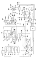
- FIG. 1 is a hydraulic circuit diagram of a construction machine control system according to a first embodiment of the present invention.
- FIG. 2 is a hydraulic circuit diagram of the construction machine control system according to the second embodiment of the present invention.
- the construction machine control system includes a variable displacement first main pump MP1 and a second main pump MP2.
- the first main pump MP1 is connected to the first circuit system.
- the second main pump MP2 is connected to the second circuit system.
- the first circuit system sequentially controls the switching valve 1 that controls the swing motor, the switching valve 2 that controls the arm cylinder, the switching valve 3 for the boom second speed that controls the boom cylinder BC, and the spare attachment in order from the upstream side.
- a switching valve 4 and a switching valve 5 for controlling a left traveling motor are provided.
- the switching valves 1 to 5 are connected in series via a neutral flow path 6 and are connected in parallel via a parallel passage 7.
- the neutral flow path 6 and the parallel path 7 are connected to the first main pump MP1.
- a throttle 8 for pilot pressure control for generating pilot pressure is connected to the neutral flow path 6 on the downstream side of the switching valve 5 for the left travel motor.
- the throttle 8 generates higher pilot pressure on the upstream side of the throttle 8 as the flow rate of the working fluid flowing through the throttle 8 increases.
- the neutral flow path 6 passes all or part of the working fluid supplied from the first main pump MP1 to the first circuit system via the throttle 8. To the tank T. In this case, since the flow rate passing through the throttle 8 is large, a high pilot pressure is generated upstream of the throttle 8.
- the switching valves 1 to 5 are switched to the full stroke state, the neutral flow path 6 is closed and the flow of fluid disappears. Accordingly, in this case, since the flow rate flowing through the throttle 8 is eliminated, the pilot pressure is kept at zero. Depending on the operation amount of the switching valves 1 to 5, a part of the pump discharge amount is led to the actuator, and a part is led from the neutral flow path 6 to the tank T. In this case, the throttle 8 generates a pilot pressure corresponding to the flow rate flowing through the neutral flow path 6. That is, the throttle 8 generates a pilot pressure corresponding to the operation amount of the switching valves 1 to 5.
- a pilot flow path 9 is connected to the neutral flow path 6 between the switching valve 5 and the throttle 8.
- the pilot flow path 9 is connected to a regulator 10 that controls the tilt angle of the first main pump MP1.
- the regulator 10 controls the tilt angle of the first main pump MP1 in inverse proportion to the pilot pressure in the pilot flow path 9, and controls the amount of displacement per one rotation of the first main pump MP1. Therefore, when the switching valves 1 to 5 are switched to the full stroke state and the flow of the neutral flow path 6 is lost and the pilot pressure becomes zero, the tilt angle of the first main pump MP1 becomes maximum, and per one rotation. The push-out amount is maximized.
- the second circuit system sequentially controls the right traveling motor from the upstream side, the switching valve 11 for controlling the bucket cylinder, the boom switching valve 13 for controlling the boom cylinder BC, and the arm cylinder for second speed control.
- a switching valve 14 is provided.
- the switching valves 11 to 14 are connected in series via the neutral flow path 15.
- the switching valves 11 to 13 are connected in parallel via a parallel passage 16.
- the neutral channel 15 and the parallel channel 16 are connected to the second main pump MP2.
- a throttle 17 for pilot pressure control is connected to the neutral flow path 15 on the downstream side of the switching valve 14.
- the throttle 17 generates a higher pilot pressure on the upstream side of the throttle 17 as the flow rate of the working fluid flowing through the throttle 17 increases.
- a pilot flow path 18 is connected to the neutral flow path 15 between the most downstream switching valve 14 and the throttle 17.
- the pilot flow path 18 is connected to a regulator 19 that controls the tilt angle of the second main pump MP2.
- the regulator 19 controls the tilt angle of the second main pump MP2 in inverse proportion to the pilot pressure in the pilot flow path 18, and controls the push-out amount per rotation of the second main pump MP2. Therefore, when the switching valves 11 to 14 are switched to the full stroke state and the flow of the neutral flow path 15 is lost and the pilot pressure becomes zero, the tilt angle of the second main pump MP2 becomes maximum, and per one rotation. The push-out amount is maximized.
- the pressure sensors 20 and 21 detect the pilot pressure guided to the regulators 10 and 19 and input it to the controller C.
- the controller C is an engine which is a power source of the first main pump MP1 and the second main pump MP2, and 22 is a generator linked to the engine E.
- the switching valves 1 to 5 and 11 to 14 are switched by the pilot pressure generated according to the amount of operation of the lever of the pilot operation valve (not shown).
- the pilot operation valve is provided with a stroke detector (not shown) connected to the controller C.
- the stroke detection unit detects the operation direction and operation amount of the pilot operation valve and inputs them to the controller C.
- the controller C determines the spool strokes of the switching valves 1 to 5 and 11 to 14 from the lever operation amount of the pilot operation valve.
- the boom switching valve 13 is connected to one passage 24 communicating with the piston side chamber 23a of the boom cylinder BC and the other passage 25 communicating with the rod side chamber 23b of the boom cylinder BC.
- One passage 24 is provided with a regeneration control valve S.
- the regenerative control valve S is provided with flow passages 26 and 27.
- One flow passage 26 is provided in the middle of one passage 24 connecting the boom switching valve 13 and the piston-side chamber 23a of the boom cylinder BC.
- the other flow passage 27 is provided in the middle of the regenerative flow path 28 connecting the piston side chamber 23a and the fluid pressure motor M.
- the regenerative flow path 28 branches from a branch point 29 between the regenerative control valve S and the piston side chamber 23 a and is connected in parallel to one passage 24.
- the regenerative control valve S is provided with a spring 30 on one side and a pilot chamber 31 on the other side.
- the regenerative control valve S normally maintains the illustrated normal position by the spring force of the spring 30, and switches to the regenerative control position, which is the right position in FIG. 1, when the pilot pressure is applied to the pilot chamber 31.
- the regenerative control position which is the right position in FIG. 1, when the pilot pressure is applied to the pilot chamber 31.
- one flow passage 26 In the normal position, one flow passage 26 is fully opened and the other flow passage 27 is closed.
- the opening degree of one of the flow passages 26 is kept at a minimum, and the opening degree of the other flow passage 27 is kept at a maximum.
- the regenerative control valve S is held at a position where the force received by the pilot pressure and the spring force of the spring 30 are balanced, and controls the opening degree of the one flow passage 26 and the other flow passage 27. Note that the normal position of the regenerative control valve S is a position where the other flow passage 27 is completely closed, and when the other flow passage 27 is open even a little, that position is the regenerative control position.
- a check valve 32 is provided in the regenerative flow path 28 to allow only the flow from the regenerative control valve S to the fluid pressure motor M.
- the regenerative control valve S When the pilot pressure acts on the pilot chamber 31 of the regenerative control valve S, the regenerative control valve S is switched to the control position which is the right side position in FIG. The switching amount of the regenerative control valve S is controlled according to the pilot pressure acting on the pilot chamber 31, thereby controlling the opening degree of the flow passages 26 and 27.
- the proportional solenoid valve 33 controls the pilot pressure in the pilot chamber 31.
- One of the proportional solenoid valves 33 is provided with a spring 34, and the other is provided with a solenoid 35.
- the proportional solenoid valve 33 is normally held in the illustrated closed position, and switches to the open position when the solenoid 35 is excited.
- the solenoid 35 is connected to the controller C, and the opening degree of the proportional solenoid valve 33 is controlled according to a signal from the controller C.
- a pilot pump PP is connected to the proportional solenoid valve 33.
- a control throttle 36 communicating with the tank T is provided between the pilot chamber 31 and the proportional solenoid valve 33.
- the controller C outputs a signal corresponding to the stroke amount to the solenoid 35 when the spool stroke of the boom switching valve 13 reaches a preset stroke range. As described above, the controller C determines the spool stroke of the boom switching valve 13 according to the signal from the stroke detection unit.
- the opening degree of the proportional solenoid valve 33 is defined according to the output signal. Therefore, the discharge fluid from the pilot pump PP is supplied to the pilot chamber 31 according to the opening degree of the proportional electromagnetic valve 33. Since the pilot fluid supplied from the pilot pump PP is guided from the control throttle 36 to the tank T, a pilot pressure corresponding to the opening degree of the proportional solenoid valve 33 acts on the pilot chamber 31.
- a proportional electromagnetic pressure reducing valve may be used. In this case, the control throttle 36 becomes unnecessary, and a proportional electromagnetic pressure reducing valve may be directly connected to the pilot chamber 31.
- the regenerative control valve S controls the opening degree of the one flow passage 26 and the other flow passage 27 according to the pilot pressure. For example, when the pilot pressure is low, the opening degree of one flow passage 26 is relatively larger than that of the other flow passage 27. On the contrary, when the pilot pressure is high, the regenerative control valve S is switched against the spring force of the spring 30, so that the opening degree of one of the flow paths 26 is relative to the opening degree of the other flow path 27. Becomes smaller.
- the return fluid from the boom cylinder BC is guided to the fluid pressure motor M via the flow passage 27 and the regenerative flow passage 28 of the regenerative control valve S.
- the flow rate guided to the fluid pressure motor M is referred to as a “second supply amount”.
- the second supply amount is controlled according to the opening degree of the regeneration control valve S, and the rotation speed of the fluid pressure motor M and the rotation speed of the motor generator MG are controlled according to the second supply amount.
- the fluid pressure motor M rotates.
- the motor generator MG rotates with the power of the fluid pressure motor M to generate power.
- the electric power generated by motor generator MG is stored in battery 38 through inverter 37.
- the battery 38 is connected to the controller C, and the charged amount of the battery 38 is monitored by the controller C.
- the setting reference for the spool stroke of the boom switching valve 13 is defined based on the rated power of the motor generator MG.
- the controller C controls the solenoid 35 to maintain the opening degree of the other flow passage 27 of the regenerative control valve S, and from the boom cylinder BC.
- the return fluid is supplied to the fluid pressure motor M.
- the stroke of the boom switching valve 13 exceeds a preset range, that is, when the stroke exceeds the upper limit value of the setting reference, the opening degree of the other flow passage 27 of the regenerative control valve S is reduced, and the fluid pressure motor
- the second supply amount that is the flow rate of the return fluid supplied to M is made smaller than the first supply amount that is the flow rate returned to the boom switching valve 13.
- the rotational speed of fluid pressure motor M is controlled, and motor generator MG is prevented from rotating beyond the rated power.
- Assist pump AP rotates coaxially with fluid pressure motor M, and assist pump AP and fluid pressure motor M are linked to motor generator MG.
- the assist pump AP is connected to the first main pump MP1 and the second main pump MP2 via flow paths 39 and 40 arranged in parallel with each other.
- the discharge fluid of the assist pump AP merges with the discharge fluid of the first main pump MP1 and the second main pump MP2.
- Check valves 41 and 42 are interposed in the flow paths 39 and 40, and the check valves 41 and 42 allow only the flow from the assist pump AP to the first main pump MP1 and the second main pump MP2.
- Regulators 43 and 44 are provided in each of the fluid pressure motor M and the assist pump AP.
- the regulators 43 and 44 are connected to the controller C and control the tilt angles of the fluid pressure motor M and the assist pump AP in accordance with a signal from the controller C.
- the controller C moves the boom cylinder BC up based on the signal from the stroke detection unit. It is determined that it is time.
- the controller C determines that the boom cylinder BC is in the ascending operation, it brings the solenoid 35 of the proportional solenoid valve 33 into a non-excited state. As a result, the proportional solenoid valve 33 is held in the closed position.
- the pressure fluid discharged from the second main pump MP2 is supplied from the boom switching valve 13 to the piston side chamber 23a of the boom cylinder BC through the one passage 24 and the one flow passage 26 of the regenerative control valve S.
- the return fluid in the rod side chamber 23 b of the boom cylinder BC is returned to the tank T through the other passage 25 and the boom switching valve 13.
- the boom cylinder BC is extended.
- the controller C detects that the boom cylinder BC is based on the signal from the stroke detection unit. It is determined that it is during descending work.
- the controller C determines whether the spool stroke is within a preset stroke range based on a signal from the stroke detection unit.
- the controller C controls the excitation current for the solenoid 35 of the proportional solenoid valve 33 according to the spool stroke.
- the pilot pressure is guided to the pilot chamber 31 of the regenerative control valve S.
- the regenerative control valve S is switched to the regenerative control position in accordance with the pilot pressure, and the opening degrees of the one flow passage 26 and the other flow passage 27 are controlled.
- Controller C controls the total opening of both flow passages 26 and 27 so that the lowering speed of the boom cylinder BC becomes the speed intended by the operator determined by the amount of lever operation. At this time, the controller C performs control so that the opening degree of the flow passage 27 is larger than that of the flow passage 26. Therefore, the return fluid of the boom cylinder BC at the time of lowering is diverted at the branch point 29 and returned to the tank T via the one flow passage 26, the passage 24, and the boom switching valve 13, and the other return fluid. And the return fluid supplied to the fluid pressure motor M via the regenerative flow path 28 from the flow passage 27.
- the fluid pressure motor M When fluid is supplied to the fluid pressure motor M, the fluid pressure motor M rotates.
- the controller C controls the torque of the fluid pressure motor M by operating the regulator 43 of the fluid pressure motor M so that the lowering speed of the boom cylinder BC becomes the speed intended by the operator.
- Controller C always determines from the amount of operation of the lever of the pilot control valve whether the boom switching valve 13 is within a preset spool stroke range.
- the controller C reduces the excitation current for the solenoid 35 of the proportional solenoid valve 33 to regenerate.
- the pilot pressure acting on the pilot chamber 31 of the control valve S is lowered.
- the regenerative control valve S moves by the action of the spring 30 to narrow the opening of the flow passage 27 and relatively increase the opening of the flow passage 26.
- the flow rate supplied to the fluid pressure motor M decreases, and the rotational speed of the fluid pressure motor M decreases.
- the controller C monitors the spool stroke of the boom switching valve 13, and when the stroke exceeds a preset range, the regenerative control valve S is operated to reduce the flow rate supplied to the fluid pressure motor M.
- the motor generator MG can be prevented from rotating beyond the rated power.
- the controller C operates the regulator 44 of the assist pump AP to make the tilt angle of the assist pump AP zero. Thereby, it is possible to prevent unnecessary power from being consumed by the assist pump AP.
- the controller C adjusts the regulator of the fluid pressure motor M so that the lowering speed of the boom cylinder BC becomes the speed intended by the operator. 43 is operated to control the torque of the fluid pressure motor M.
- the controller C monitors the amount of electricity stored in the battery 38, and if the battery 38 is in a fully charged state, the controller C operates the regulator 43 provided in the fluid pressure motor M, thereby adjusting the tilt angle of the fluid pressure motor M. Set to zero.
- the controller C does not affect the descending speed of the boom cylinder BC even when the load becomes zero.
- the proportional solenoid valve 33 is controlled to control the flow passages 26 and 27 of the regenerative control valve S.
- the construction machine control system of the present embodiment is different from the first embodiment only in that it includes a bleed-off valve BV provided in the regenerative flow path 28 and a proportional electromagnetic valve 45 that controls the bleed-off valve BV. Therefore, the same components as those in the first embodiment are denoted by the same reference numerals and detailed description thereof is omitted.
- the bleed-off valve BV is provided with a spring 46 on one side and a pilot chamber 47 on the other side.
- the bleed-off valve BV is normally kept in the closed position, which is the normal position shown in the figure, by the action of the spring force of the spring 46.
- the pilot pressure is applied to the pilot chamber 47, the bleed-off valve BV is moved to the control position, which is the right position in FIG. Switch.
- the bleed-off valve BV is switched to the control position, a part of the flow rate of the regenerative flow path 28 is guided to the tank T.
- the opening degree of the bleed-off valve BV is controlled by the pilot pressure acting on the pilot chamber 47.
- the proportional solenoid valve 45 controls the pilot pressure in the pilot chamber 47.
- the proportional solenoid valve 45 is provided with a spring 48 on one side and a solenoid 49 on the other side.
- the proportional solenoid valve 45 is normally held in the illustrated closed position, and switches to the open position when the solenoid 49 is excited.
- the solenoid 49 is connected to the controller C, and the opening degree of the proportional solenoid valve 45 in the process of switching from the closed position to the open position is controlled according to a signal from the controller C.
- a pilot pump PP is connected to the proportional solenoid valve 45.
- a control throttle 50 communicating with the tank T is provided between the pilot chamber 47 and the proportional solenoid valve 45.
- the controller C outputs a signal corresponding to the stroke amount to the solenoid 49 when the spool stroke of the boom switching valve 13 is greater than or equal to a preset stroke, that is, greater than or equal to the upper limit value of the setting reference.
- the controller C determines the spool stroke of the boom switching valve 13 according to the lever operation amount provided in the pilot operation valve.
- the opening degree of the proportional solenoid valve 45 is determined according to the output signal.
- the fluid discharged from the pilot pump PP is supplied to the pilot chamber 47 of the bleed-off valve BV according to the opening degree of the proportional solenoid valve 45. Since the pilot fluid supplied from the pilot pump PP is guided from the control throttle 50 to the tank T, a pilot pressure corresponding to the opening degree of the proportional solenoid valve 45 acts on the pilot chamber 47.
- the bleed-off valve BV When the pilot pressure is applied to the pilot chamber 47 of the bleed-off valve BV, the bleed-off valve BV is switched to the control position, and the opening degree of the bleed-off valve BV is controlled according to the pilot pressure. Accordingly, a part of the flow rate supplied to the regenerative flow path 28 is returned to the tank T via the bleed-off valve BV.
- an electromagnetic proportional pressure reducing valve may be used.
- the control throttle 50 becomes unnecessary, and an electromagnetic proportional pressure reducing valve may be directly connected to the pilot chamber 47.
Landscapes
- Engineering & Computer Science (AREA)
- General Engineering & Computer Science (AREA)
- Mining & Mineral Resources (AREA)
- Civil Engineering (AREA)
- Structural Engineering (AREA)
- Chemical & Material Sciences (AREA)
- Analytical Chemistry (AREA)
- Physics & Mathematics (AREA)
- Fluid Mechanics (AREA)
- Mechanical Engineering (AREA)
- Fluid-Pressure Circuits (AREA)
- Operation Control Of Excavators (AREA)
Abstract
Description
Claims (5)
- 建設機械の制御システムであって、
ピストンによってピストン側室とロッド側室とに区画され、前記ピストン側室又は前記ロッド側室に作動流体が供給されることで伸縮作動してブームを駆動するブームシリンダと、
前記ピストン側室又は前記ロッド側室に供給する作動流体の供給量をスプールのストロークによって調整するブーム用切換弁と、
前記ピストン側室から導かれる戻り流体によって回転してモータジェネレータを駆動する流体圧モータと、
前記ピストン側室と前記ブーム用切換弁及び記流体圧モータとを連通し、前記ピストン側室から前記ブーム用切換弁に供給される作動流体の供給量である第1供給量と前記ピストン側室から前記流体圧モータに供給される作動流体の供給量である第2供給量とを調整する回生制御弁と、
前記スプールのストローク量が上限値以上となった場合、前記第2供給量が前記第1供給量より小さくなるように前記回生制御弁を制御するコントローラと、
を備える建設機械の制御システム。 - 建設機械の制御システムであって、
ピストンによりピストン側室及びロッド側室が画成されて、前記ピストン側室又は前記ロッド側室に作動流体が供給されることにより伸縮作動してブームを駆動するブームシリンダと、
前記ピストン側室又は前記ロッド側室に供給する作動流体の供給量を前記スプールのストロークによって調整するブーム用切換弁と、
前記ピストン側室から導かれる戻り流体によって回転してモータジェネレータを駆動する流体圧モータと、
前記ピストン側室と前記ブーム用切換弁及び前記流体圧モータとを連通し、前記ピストン側室から前記ブーム用切換弁に供給される作動流体の供給量と前記ピストン側室から前記流体圧モータに供給される作動流体の供給量とを調整する回生制御弁と、
前記回生制御弁と前記流体圧モータとを結ぶ通路に設けられ、前記ピストン側室とドレン側のタンクとを連通又は遮断するブリードオフ弁と、
前記スプールのストローク量が上限値以上となった場合、ストローク量に応じて前記ブリードオフ弁の開度を制御して前記ピストン側室と前記タンクとを連通させるコントローラと、
を備える建設機械の制御システム。 - 請求項1に記載の建設機械の制御システムであって、
前記回生制御弁は、比例電磁弁を介してパイロット圧源に接続されるパイロット室と、前記パイロット室と対向する側に設けられ前記スプールを前記パイロット室側へ押圧するばね力を発揮するスプリングと、を有し、
前記コントローラは、前記比例電磁弁を制御して前記パイロット室にパイロット圧を作用させることで前記回生制御弁の開度を制御する、
建設機械の制御システム。 - 請求項1に記載の建設機械の制御システムであって、
前記上限値は、前記モータジェネレータの定格動力に基づいて設定される、
建設機械の制御システム。 - 請求項3に記載の建設機械の制御システムであって、
前記比例電磁弁は、比例電磁減圧弁である、
建設機械の制御システム。
Priority Applications (4)
| Application Number | Priority Date | Filing Date | Title |
|---|---|---|---|
| US14/406,535 US9835187B2 (en) | 2012-07-25 | 2013-07-23 | Control system for construction machine |
| CN201380031577.2A CN104379945B (zh) | 2012-07-25 | 2013-07-23 | 建筑机械的控制系统 |
| DE201311003659 DE112013003659T5 (de) | 2012-07-25 | 2013-07-23 | Steuersystem für eine Baumaschine |
| KR1020147033733A KR101652619B1 (ko) | 2012-07-25 | 2013-07-23 | 건설 기계의 제어 시스템 |
Applications Claiming Priority (2)
| Application Number | Priority Date | Filing Date | Title |
|---|---|---|---|
| JP2012164518A JP5828481B2 (ja) | 2012-07-25 | 2012-07-25 | 建設機械の制御装置 |
| JP2012-164518 | 2012-07-25 |
Publications (1)
| Publication Number | Publication Date |
|---|---|
| WO2014017492A1 true WO2014017492A1 (ja) | 2014-01-30 |
Family
ID=49997301
Family Applications (1)
| Application Number | Title | Priority Date | Filing Date |
|---|---|---|---|
| PCT/JP2013/069930 Ceased WO2014017492A1 (ja) | 2012-07-25 | 2013-07-23 | 建設機械の制御システム |
Country Status (6)
| Country | Link |
|---|---|
| US (1) | US9835187B2 (ja) |
| JP (1) | JP5828481B2 (ja) |
| KR (1) | KR101652619B1 (ja) |
| CN (1) | CN104379945B (ja) |
| DE (1) | DE112013003659T5 (ja) |
| WO (1) | WO2014017492A1 (ja) |
Cited By (4)
| Publication number | Priority date | Publication date | Assignee | Title |
|---|---|---|---|---|
| JP2016014398A (ja) * | 2014-06-30 | 2016-01-28 | 日立建機株式会社 | 建設機械の油圧システム |
| US20160138619A1 (en) * | 2014-11-14 | 2016-05-19 | Caterpillar Inc. | Conserve Energy Through Independent Pump Control in a Hydraulic System |
| CN105839690A (zh) * | 2014-12-08 | 2016-08-10 | 胡斯可国际股份有限公司 | 液压系统的选择性地接合的再生的系统和方法 |
| CN108026713A (zh) * | 2015-09-16 | 2018-05-11 | 卡特彼勒Sarl | 液压作业机器的液压泵控制系统 |
Families Citing this family (9)
| Publication number | Priority date | Publication date | Assignee | Title |
|---|---|---|---|---|
| WO2013095208A1 (en) * | 2011-12-22 | 2013-06-27 | Volvo Construction Equipment Ab | A method for controlling lowering of an implement of a working machine |
| JP6155159B2 (ja) * | 2013-10-11 | 2017-06-28 | Kyb株式会社 | ハイブリッド建設機械の制御システム |
| CN106030123B (zh) | 2014-05-16 | 2018-03-13 | 日立建机株式会社 | 作业机械的液压油能量再生装置 |
| US9790644B2 (en) * | 2015-12-14 | 2017-10-17 | Harsco Technologies LLC | Vertical ride quality system for a rail vehicle |
| CN106368258B (zh) * | 2016-11-16 | 2019-04-09 | 临沂常泰工程机械有限公司 | 电动装载机 |
| EP3581809B1 (en) * | 2017-02-10 | 2023-08-16 | Eagle Industry Co., Ltd. | Fluid pressure circuit |
| JP7137160B2 (ja) * | 2018-06-13 | 2022-09-14 | Smc株式会社 | エアシリンダの流体回路 |
| JP7473337B2 (ja) * | 2019-12-27 | 2024-04-23 | 株式会社小松製作所 | 作業機械の制御システム、作業機械、及び作業機械の制御方法 |
| CN118318107A (zh) | 2021-12-09 | 2024-07-09 | 伊格尔工业股份有限公司 | 流体压回路 |
Citations (5)
| Publication number | Priority date | Publication date | Assignee | Title |
|---|---|---|---|---|
| JP2000170705A (ja) * | 1998-12-01 | 2000-06-20 | Hitachi Constr Mach Co Ltd | 建設機械の発電用油圧回路 |
| JP2003329012A (ja) * | 2002-05-15 | 2003-11-19 | Komatsu Ltd | 建設機械 |
| JP2007263157A (ja) * | 2006-03-27 | 2007-10-11 | Kayaba Ind Co Ltd | エネルギー変換装置 |
| JP2011179541A (ja) * | 2010-02-26 | 2011-09-15 | Kyb Co Ltd | 建設機械の制御装置 |
| JP2012013160A (ja) * | 2010-07-01 | 2012-01-19 | Kyb Co Ltd | エネルギ回生システム |
Family Cites Families (7)
| Publication number | Priority date | Publication date | Assignee | Title |
|---|---|---|---|---|
| JPH02229329A (ja) * | 1989-02-28 | 1990-09-12 | Kobe Steel Ltd | 油圧ショベルの旋回制御方法および装置 |
| JP4067596B2 (ja) * | 1997-03-07 | 2008-03-26 | 日立建機株式会社 | 建設機械の油圧制御装置 |
| JP2004011168A (ja) * | 2002-06-04 | 2004-01-15 | Komatsu Ltd | 建設機械 |
| KR100929421B1 (ko) * | 2007-10-22 | 2009-12-03 | 볼보 컨스트럭션 이키프먼트 홀딩 스웨덴 에이비 | 중장비용 유압제어밸브 |
| JP5078693B2 (ja) * | 2008-03-26 | 2012-11-21 | カヤバ工業株式会社 | ハイブリッド建設機械の制御装置 |
| JP5172477B2 (ja) * | 2008-05-30 | 2013-03-27 | カヤバ工業株式会社 | ハイブリッド建設機械の制御装置 |
| CN102493516B (zh) * | 2011-12-12 | 2013-11-20 | 中联重科股份有限公司 | 挖掘机油箱及具有该油箱的挖掘机 |
-
2012
- 2012-07-25 JP JP2012164518A patent/JP5828481B2/ja not_active Expired - Fee Related
-
2013
- 2013-07-23 US US14/406,535 patent/US9835187B2/en not_active Expired - Fee Related
- 2013-07-23 DE DE201311003659 patent/DE112013003659T5/de not_active Ceased
- 2013-07-23 KR KR1020147033733A patent/KR101652619B1/ko not_active Expired - Fee Related
- 2013-07-23 WO PCT/JP2013/069930 patent/WO2014017492A1/ja not_active Ceased
- 2013-07-23 CN CN201380031577.2A patent/CN104379945B/zh not_active Expired - Fee Related
Patent Citations (5)
| Publication number | Priority date | Publication date | Assignee | Title |
|---|---|---|---|---|
| JP2000170705A (ja) * | 1998-12-01 | 2000-06-20 | Hitachi Constr Mach Co Ltd | 建設機械の発電用油圧回路 |
| JP2003329012A (ja) * | 2002-05-15 | 2003-11-19 | Komatsu Ltd | 建設機械 |
| JP2007263157A (ja) * | 2006-03-27 | 2007-10-11 | Kayaba Ind Co Ltd | エネルギー変換装置 |
| JP2011179541A (ja) * | 2010-02-26 | 2011-09-15 | Kyb Co Ltd | 建設機械の制御装置 |
| JP2012013160A (ja) * | 2010-07-01 | 2012-01-19 | Kyb Co Ltd | エネルギ回生システム |
Cited By (7)
| Publication number | Priority date | Publication date | Assignee | Title |
|---|---|---|---|---|
| JP2016014398A (ja) * | 2014-06-30 | 2016-01-28 | 日立建機株式会社 | 建設機械の油圧システム |
| US9926950B2 (en) * | 2014-06-30 | 2018-03-27 | Hitachi Construction Machinery Co., Ltd. | Hydraulic system for construction machinery |
| US20160138619A1 (en) * | 2014-11-14 | 2016-05-19 | Caterpillar Inc. | Conserve Energy Through Independent Pump Control in a Hydraulic System |
| CN105839690A (zh) * | 2014-12-08 | 2016-08-10 | 胡斯可国际股份有限公司 | 液压系统的选择性地接合的再生的系统和方法 |
| CN105839690B (zh) * | 2014-12-08 | 2020-06-12 | 胡斯可国际股份有限公司 | 液压系统的选择性地接合的再生的系统和方法 |
| CN108026713A (zh) * | 2015-09-16 | 2018-05-11 | 卡特彼勒Sarl | 液压作业机器的液压泵控制系统 |
| CN108026713B (zh) * | 2015-09-16 | 2021-03-09 | 卡特彼勒Sarl | 液压作业机器的液压泵控制系统 |
Also Published As
| Publication number | Publication date |
|---|---|
| CN104379945B (zh) | 2016-05-11 |
| CN104379945A (zh) | 2015-02-25 |
| DE112013003659T5 (de) | 2015-04-16 |
| JP5828481B2 (ja) | 2015-12-09 |
| KR101652619B1 (ko) | 2016-08-30 |
| US9835187B2 (en) | 2017-12-05 |
| KR20150016296A (ko) | 2015-02-11 |
| JP2014025498A (ja) | 2014-02-06 |
| US20150152900A1 (en) | 2015-06-04 |
Similar Documents
| Publication | Publication Date | Title |
|---|---|---|
| WO2014017492A1 (ja) | 建設機械の制御システム | |
| JP5172477B2 (ja) | ハイブリッド建設機械の制御装置 | |
| KR101507646B1 (ko) | 하이브리드 건설 기계의 제어 시스템 | |
| KR101572288B1 (ko) | 하이브리드 건설기계의 제어장치 | |
| KR101568440B1 (ko) | 하이브리드 건설기계의 제어장치 | |
| US10179987B2 (en) | Control system for hybrid construction machine | |
| JP5908371B2 (ja) | ハイブリッド建設機械の制御装置 | |
| US8655558B2 (en) | Control system for hybrid construction machine | |
| KR20120123095A (ko) | 하이브리드 건설 기계의 제어 시스템 | |
| WO2010128645A1 (ja) | ハイブリッド建設機械の制御装置 | |
| WO2011004881A1 (ja) | ハイブリッド建設機械の制御装置 | |
| JP2011017428A (ja) | ハイブリッド建設機械 | |
| WO2009119704A1 (ja) | ハイブリッド建設機械の制御装置 | |
| JP2013200023A (ja) | 建設機械の制御装置 | |
| JP4942699B2 (ja) | ハイブリッド建設機械の制御装置 | |
| WO2011145432A1 (ja) | ハイブリッド作業機械 | |
| JP5197479B2 (ja) | ハイブリッド建設機械 | |
| US9359743B2 (en) | Control system for hybrid construction machine | |
| JP5197478B2 (ja) | ハイブリッド建設機械 |
Legal Events
| Date | Code | Title | Description |
|---|---|---|---|
| WWE | Wipo information: entry into national phase |
Ref document number: 201380031577.2 Country of ref document: CN |
|
| 121 | Ep: the epo has been informed by wipo that ep was designated in this application |
Ref document number: 13822869 Country of ref document: EP Kind code of ref document: A1 |
|
| ENP | Entry into the national phase |
Ref document number: 20147033733 Country of ref document: KR Kind code of ref document: A |
|
| WWE | Wipo information: entry into national phase |
Ref document number: 14406535 Country of ref document: US |
|
| WWE | Wipo information: entry into national phase |
Ref document number: 112013003659 Country of ref document: DE Ref document number: 1120130036592 Country of ref document: DE |
|
| 122 | Ep: pct application non-entry in european phase |
Ref document number: 13822869 Country of ref document: EP Kind code of ref document: A1 |