WO2014017440A1 - 無線通信方法、無線通信システム及び無線基地局 - Google Patents
無線通信方法、無線通信システム及び無線基地局 Download PDFInfo
- Publication number
- WO2014017440A1 WO2014017440A1 PCT/JP2013/069803 JP2013069803W WO2014017440A1 WO 2014017440 A1 WO2014017440 A1 WO 2014017440A1 JP 2013069803 W JP2013069803 W JP 2013069803W WO 2014017440 A1 WO2014017440 A1 WO 2014017440A1
- Authority
- WO
- WIPO (PCT)
- Prior art keywords
- extended
- resource
- ereg
- downlink control
- base station
- Prior art date
Links
- 238000000034 method Methods 0.000 title claims abstract description 45
- 238000004891 communication Methods 0.000 title claims abstract description 44
- 238000013507 mapping Methods 0.000 claims abstract description 63
- 230000005540 biological transmission Effects 0.000 description 47
- 238000012545 processing Methods 0.000 description 34
- 238000010586 diagram Methods 0.000 description 11
- 125000004122 cyclic group Chemical group 0.000 description 9
- 238000013459 approach Methods 0.000 description 8
- 230000000694 effects Effects 0.000 description 7
- 101150071746 Pbsn gene Proteins 0.000 description 5
- 238000005259 measurement Methods 0.000 description 5
- 230000007274 generation of a signal involved in cell-cell signaling Effects 0.000 description 4
- 238000007726 management method Methods 0.000 description 3
- 230000011664 signaling Effects 0.000 description 3
- 101000741965 Homo sapiens Inactive tyrosine-protein kinase PRAG1 Proteins 0.000 description 2
- 102100038659 Inactive tyrosine-protein kinase PRAG1 Human genes 0.000 description 2
- 230000002776 aggregation Effects 0.000 description 2
- 238000004220 aggregation Methods 0.000 description 2
- 238000012937 correction Methods 0.000 description 2
- 239000006185 dispersion Substances 0.000 description 2
- 238000005516 engineering process Methods 0.000 description 2
- 238000003780 insertion Methods 0.000 description 2
- 230000037431 insertion Effects 0.000 description 2
- 238000012935 Averaging Methods 0.000 description 1
- 101001056707 Homo sapiens Proepiregulin Proteins 0.000 description 1
- 102100025498 Proepiregulin Human genes 0.000 description 1
- 238000004364 calculation method Methods 0.000 description 1
- 230000008878 coupling Effects 0.000 description 1
- 238000010168 coupling process Methods 0.000 description 1
- 238000005859 coupling reaction Methods 0.000 description 1
- 230000007774 longterm Effects 0.000 description 1
- 238000013468 resource allocation Methods 0.000 description 1
Images


Classifications
-
- H—ELECTRICITY
- H04—ELECTRIC COMMUNICATION TECHNIQUE
- H04L—TRANSMISSION OF DIGITAL INFORMATION, e.g. TELEGRAPHIC COMMUNICATION
- H04L5/00—Arrangements affording multiple use of the transmission path
- H04L5/003—Arrangements for allocating sub-channels of the transmission path
- H04L5/0048—Allocation of pilot signals, i.e. of signals known to the receiver
-
- H—ELECTRICITY
- H04—ELECTRIC COMMUNICATION TECHNIQUE
- H04J—MULTIPLEX COMMUNICATION
- H04J11/00—Orthogonal multiplex systems, e.g. using WALSH codes
-
- H—ELECTRICITY
- H04—ELECTRIC COMMUNICATION TECHNIQUE
- H04L—TRANSMISSION OF DIGITAL INFORMATION, e.g. TELEGRAPHIC COMMUNICATION
- H04L5/00—Arrangements affording multiple use of the transmission path
- H04L5/003—Arrangements for allocating sub-channels of the transmission path
- H04L5/0053—Allocation of signalling, i.e. of overhead other than pilot signals
-
- H—ELECTRICITY
- H04—ELECTRIC COMMUNICATION TECHNIQUE
- H04W—WIRELESS COMMUNICATION NETWORKS
- H04W16/00—Network planning, e.g. coverage or traffic planning tools; Network deployment, e.g. resource partitioning or cells structures
- H04W16/24—Cell structures
- H04W16/28—Cell structures using beam steering
-
- H—ELECTRICITY
- H04—ELECTRIC COMMUNICATION TECHNIQUE
- H04W—WIRELESS COMMUNICATION NETWORKS
- H04W72/00—Local resource management
- H04W72/20—Control channels or signalling for resource management
- H04W72/23—Control channels or signalling for resource management in the downlink direction of a wireless link, i.e. towards a terminal
-
- H—ELECTRICITY
- H04—ELECTRIC COMMUNICATION TECHNIQUE
- H04L—TRANSMISSION OF DIGITAL INFORMATION, e.g. TELEGRAPHIC COMMUNICATION
- H04L5/00—Arrangements affording multiple use of the transmission path
- H04L5/003—Arrangements for allocating sub-channels of the transmission path
- H04L5/0048—Allocation of pilot signals, i.e. of signals known to the receiver
- H04L5/0051—Allocation of pilot signals, i.e. of signals known to the receiver of dedicated pilots, i.e. pilots destined for a single user or terminal
Definitions
- the present invention relates to a radio communication method, a radio communication system, and a radio base station in a next generation radio communication system.
- LTE Long Term Evolution
- OFDMA Orthogonal Frequency Division Multiple Access
- SC-FDMA Single Carrier Frequency Division Multiple Access
- LTE-A LTE Advanced or LTE enhancement
- MIMO Multi Input Multi Output
- a plurality of transmission / reception antennas are prepared in a transceiver, and different transmission information sequences are transmitted simultaneously from different transmission antennas.
- LTE-A which is a successor system of LTE
- MU-MIMO multi-user MIMO
- Hetnet Heterogeneous network
- CoMP Coordinatd Multi-Point
- a method of transmitting more downlink control information by extending the radio resource area for the downlink control channel can be considered.
- how to allocate radio resources to the downlink control information that is, how to map the downlink control information to the resource area for the extended control channel is a problem. It becomes.
- the present invention has been made in view of this point, and an object of the present invention is to provide a radio communication method, a radio communication system, and a radio base station that can appropriately allocate radio resources to downlink control information in an extended downlink control channel.
- a radio communication method of the present invention is a radio communication method in a radio communication system in which a radio base station transmits downlink control information for each user terminal via an extended downlink control channel that is frequency division multiplexed with a downlink shared data channel,
- the radio base station generates the downlink control information in an extended control channel element (eCCE) unit composed of a plurality of extended resource element groups (eREGs), and a plurality of resource areas for the extended downlink control channel Mapping the downlink control information in units of extended resource element groups (eREG), wherein the extended resource element group (eREG) is composed of a plurality of resource elements (RE), and the radio base station Are different extended resource element groups (eREGs) in each resource area.
- Resource elements formed (RE) number becomes uniform, and a plurality of resource elements constituting an expanded resource element group (1eREG) (RE) is characterized by performing the mapping so as to disperse into a plurality of OFDM symbols.
- radio resources can be appropriately allocated to downlink control information in the extended downlink control channel.
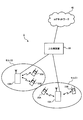
- FIG. 1 is a diagram illustrating an example of Hetnet to which MU-MIMO transmission is applied.
- the system shown in FIG. 1 has a hierarchical configuration in which a small base station (for example, RRH: Remote Radio Head, etc.) having a local coverage area is provided in the coverage area of a radio base station (for example, eNB: eNodeB).
- a radio base station for example, eNB: eNodeB
- UE User Equipment
- # 2 data for a plurality of user terminals UE # 1 and # 2 are simultaneously transmitted from a plurality of antennas of a radio base station.
- data for a plurality of user terminals UE # 3 and # 4 are simultaneously transmitted from a plurality of antennas of a plurality of small base stations.
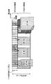
- FIG. 2 is a diagram illustrating an example of a radio frame (for example, one subframe) to which downlink MU-MIMO transmission is applied.
- radio resources for a downlink control channel (PDCCH: Physical Downlink Control Channel) from the beginning to a predetermined OFDM symbol (maximum 3 OFDM symbols) in each subframe. It is secured as a region (PDCCH region).
- PDSCH area for a downlink shared data channel (PDSCH: Physical Downlink Shared Channel) is secured in radio resources after a predetermined symbol from the top of the subframe.
- Downlink control information for user terminals UE (here, UE # 1 to # 4) is allocated to the PDCCH region.
- DCI includes data allocation information for the user terminal UE in the PDSCH region.
- the user terminal UE # 2 receives data for the user terminal UE # 2 assigned to the PDSCH region based on the DCI for the user terminal UE # 2 assigned to the PDCCH region.
- DCI allocation areas cannot be secured for all user terminals UE # 1 to # 6 in the PDCCH area.
- DCI for user terminals UE # 5 and # 6 cannot be assigned.
- the effect of improving the use efficiency of radio resources by MU-MIMO transmission may not be obtained sufficiently.
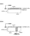
- the PDCCH allocation region is expanded from the beginning of the subframe to a control region other than a maximum of 3 OFDM symbols (the PDCCH region is expanded to an existing PDSCH region after 4 OFDM symbols). Can be considered.
- a method for extending the PDCCH region as shown in FIG. 3A, a method of time-division multiplexing PDSCH and PDCCH in the existing PDSCH region (TDM approach), as shown in FIG. 3B, PDSCH and PDCCH in the existing PDSCH region. And frequency division multiplexing (FDM approach).
- PDCCHs are arranged over the entire system band in some OFDM symbols after 4 OFDM symbols in a subframe.
- PDCCH is arranged in a part of the system band in all OFDM symbols after 4 OFDM symbols in a subframe.
- the PDCCH frequency-division multiplexed with the PDSCH by this FDM approach can be demodulated using a demodulation reference signal (DM-RS: DeModulation-Reference Signal) which is a user-specific reference signal.
- DM-RS DeModulation-Reference Signal
- enhanced PDCCH enhanced PDCCH
- This enhanced PDCCH may be called an enhanced downlink control channel, ePDCCH, E-PDCCH, FDM type PDCCH, UE-PDCCH, or the like.
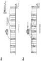
- FIG. 4 is a diagram illustrating an example of a DCI mapping method in the extended PDCCH.
- FIG. 4A shows an example of local mapping
- FIG. 4B shows an example of distributed mapping.
- the extended PDCCH resource is composed of a predetermined number of resource block pairs (PRB (Physical Resource Block) pairs, hereinafter referred to as “PRB pairs”) distributed in the system band.
- PRB pairs Physical Resource Block pairs
- the PRB pair is composed of two PRBs continuous in the time direction (first half slot and second half slot), and is identified by a PRB index given in the frequency direction.
- the plurality of PRB pairs constituting the extended PDCCH resource are determined by higher layers or specifications.
- the PRB index for identifying each of the plurality of PRB pairs is notified to the user terminal UE by higher layer signaling or the like.
- 1DCI is locally mapped to a specific PRB pair constituting the extended PDCCH resource. Specifically, 1DCI is mapped within 1 PRB pair (for example, PRB pair with the best channel quality) based on the CQI fed back from the user terminal UE. In local mapping, frequency scheduling gain can be obtained by using CQI.
- PDSCH may be mapped to a PRB pair to which DCI is not mapped among a plurality of PRB pairs constituting the extended PDCCH resource.
- 1DCI is distributed and mapped to a plurality of PRB pairs constituting the extended PDCCH resource.
- 1DCI is divided into a plurality of divided units, and each divided unit is distributed and mapped to the plurality of PRB pairs (may be all PRB pairs).
- frequency diversity gain can be obtained by dispersing 1DCI in the system band.
- each DCI is divided into a plurality of divided units, and each divided unit is distributed and mapped to a plurality of PRB pairs constituting the extended PDCCH resource.
- the downlink control information (DCI) allocated to the existing PDCCH arranged from the top of the subframe to the predetermined OFDM symbol is generated in units of control channel elements (CCE).
- the CCE is composed of nine resource element groups (REG: Resource Element Group), and each REG is composed of a set of four resource elements (RE: Resource Element).
- the present inventors are considering generating downlink control information (DCI) to be assigned to the extended PDCCH in units of predetermined control channel elements so that the existing CCE can be reused (for example, blind decoding).
- DCI downlink control information
- eCCE enhanced Channel Control Element
- the extended control channel element can be composed of a plurality of resource element groups, and distributedly mapped in units of resource elements to a plurality of PRB pairs for extended PDCCH.
- a resource element group constituting an extended control channel element eCCE
- eREG enhanced Resource Element Group
- FIG. 5 is a diagram illustrating an example of distributed mapping when an extended PDCCH is provided.
- a system band is composed of 11 physical resource blocks (PRB pairs).
- the 11 PRB pairs are assigned PRB indexes (PRB # 0 to # 10) along the frequency direction.
- the extended PDCCH is set to four PRB pairs # 1, # 4, # 8, and # 10 (see FIG. 5A).
- the extended PDCCH is mapped in units of PRBs, but is not limited to this. For example, it may be performed in units of resource block groups (RBGs) composed of a plurality of continuous PRBs (for example, two or four PRB pairs).
- RBGs resource block groups
- each PRB pair is composed of 4 eCCEs
- the total number of eCCEs is 16.
- different eCCE index numbers # 0 to # 15 are assigned to each eCCE (see FIG. 5B).
- Each eCCE is mapped to a PRB pair (see FIG. 5C) and then transmitted to the user terminal.
- each eCCE is distributed to a plurality of PRB pairs (for example, PRB pairs # 1, # 4, # 8, and # 10).
- the mapping can be performed in units of division units (eREG) (see FIG. 5C).
- FIG. 5C shows a case where eCCE with index number 0 (eCCE # 0) is mapped to eREG (eREG # 0) with index number 0 of PRB # 1 and eREG # 4 with PRB # 8. That is, the two eREGs constituting the eCCE # 0 are mapped as eREG # 0 of PRB # 1 and eREG # 4 of PRB # 8.
- an eREG which is a mapping unit of eCCE for a PRB pair, with a predetermined number of resource elements (RE).
- RE resource elements
- the number of REs that can be used as extended PDCCH is defined as a predetermined value (for example, 144), and the number of REs of the predetermined value Based on this, the number of eREG divisions (the number of eREGs included in one PRB pair) can be determined.
- the 144 corresponds to the total number of REs in one PRB pair (168) minus the number of REs in which DM-RSs are arranged (24). To do.
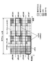
- FIG. 6 when one PRB pair is divided into eight eREGs (eREG # 0 to # 7), a method of providing eREG by dividing the PRB pair in a predetermined frequency / time axis direction is considered. It is done.
- the eREG when one PRB pair is divided into eight eREGs (eREG # 0 to # 7), the eREG is provided by dividing into four in the frequency axis direction and dividing into two in the time axis direction (first half slot and second half slot). Shows the case.
- 1PRB is composed of 4 eCCEs (eg, 1eCCE is 36 REs)
- 1eCCE can be composed of 2 eREGs. That is, FIG. 6 shows a case where 1 eCCE composed of two eREGs is mapped to a PRB pair in units of eREG.
- each eREG when each eREG is provided in an area partitioned in the frequency axis direction and the time axis direction in one PRB pair, REs constituting the 1 eREG are collectively arranged in a predetermined area. That is, as shown in FIG. 6, the eREGs to which the respective index numbers are attached are provided collectively in areas divided in the frequency and time axis directions.
- the number of REs that can be used for the extended PDCCH is different (non-uniform) between eREGs assigned different index numbers.
- the RE in the region where the DM-RS is arranged in one PRB pair cannot be used for the extended PDCCH.
- eREG # 3 includes 17 REs
- eREG # 5 includes 19 REs. Therefore, depending on the combination of a plurality of eREGs, the sizes may be different (non-uniform) among the plurality of eCCEs.
- each eREG is aggregated and provided in a predetermined area within one PRB pair, a large number of REs constituting the 1eREG are arranged in the same OFDM symbol.
- the total power is limited within one OFDM symbol, if the eREGs are aggregated in a predetermined area, there is a possibility that the power utilization efficiency cannot be sufficiently achieved without averaging between the eREGs.
- the present inventors have mapped a plurality of REs constituting each eREG and / or a plurality of eREGs constituting each eCCE in a resource region (PRB, RBG, etc.) where the extended PDCCH is located. It has been found that downlink control information can be appropriately allocated to the resource region for the extended PDCCH by controlling the method.
- the present inventors have found that power utilization efficiency can be improved by distributing a plurality of REs constituting 1eREG into a plurality of OFDM symbols in a resource region where the extended PDCCH is arranged. Also, at least in the existing LTE system (Rel. 8 to Rel10), a region where a control channel (existing PDCCH arranged in 1 to 3 OFDM symbols from the top of a subframe) is arranged, a reference signal (for example, CRS (Cell specific) Reference REGISTER (Signal Signal)) and RE in the area where the data channel (existing PDSCH) is located are allocated uniformly to the REs constituting the eREG of each index number.
- CRS Cell specific
- Reference REGISTER Signal
- a plurality of eREGs constituting 1 eCCE are distributed to a plurality of resource regions where extended PDCCHs are arranged, and downlink control information (DCI) is mapped so that index numbers of the plurality of eREGs constituting 1 eCCE are different from each other.
- DCI downlink control information
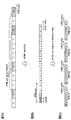
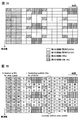
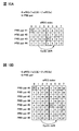
- EREG index assignment method With reference to FIG. 7, a method of assigning an eREG index to each RE (arrangement pattern control of a plurality of REs constituting each eREG) in a resource region where the ePDCCH is arranged will be described.
- the resource area is described by taking, as an example, a 1PRB pair in a normal cyclic prefix / normal subframe, but is not limited thereto.
- FIG. 7A shows a resource region (1PRB) in which ePDCCH is arranged.
- the resource region shown in FIG. 7 includes first to third regions that can be used for ePDCCH, and a fourth region in which DM-RSs are arranged and not used for ePDCCH.
- the first region, the second region, and the third region are each arranged in the existing LTE system (or another resource region in which ePDCCH is not arranged) in PDSCH and 1 to 3 OFDM symbols from the top of the subframe. This corresponds to an area where the existing PDCCH and the reference signal (CRS) are arranged.
- CRS reference signal
- the reference signal (CRS) is arranged in the resource area where the ePDCCH is arranged
- the first area and the second area are used for the ePDCCH and the reference signal and the existing PDCCH are arranged
- the first area is used for ePDCCH. That is, in the resource region, the first region is the region most likely to be used for eCCE mapping.
- mapping is performed so that the number of REs constituting different eREGs is uniform and a plurality of REs constituting one eREG are distributed over a plurality of OFDM symbols.
- the uniform number of REs constituting different eREGs is not necessarily limited to the case where the number of REs is the same between different eREGs, and the difference in the number of REs between eREGs is made as small as possible (preferably different eREGs). The difference in the number of REs that constitute each is set to be within 1).
- the REs in the regions (first region to third region) that can be used for ePDCCH are numbered (numbered) in order from the REs that are likely to be used for ePDCCH (see FIG. 7B).
- the regions (second region and third region) that may be used for other signals are numbered.
- FIG. 7B shows a case where the numbering is performed on the second area and then the numbering is performed on the third area, the numbering may be performed in the reverse order. Further, the numbering is not performed for the RE in the fourth area where the DM-RS is arranged.
- numbering is performed in order along the frequency axis direction (vertical direction in FIG. 7B), starting from the RE in the region having the smallest frequency and time in the first region.
- a cyclic shift may be applied to each OFDM symbol as shown in FIG. 7B so that the REs constituting each eREG are dispersed as much as possible.
- REs in the first area are numbered from 0 to 95.
- the REs in the second region are numbered from 96 to 127 along one OFDM symbol from the 3OFDM symbol side, and then the REs in the third region are numbered from 128 to 143. .
- Step 2 a modulo operation is applied to the index assigned to each RE in step 1 using the number N of eREGs provided in the PRB pair. This case corresponds to the case where the PRB pair is divided into N eREGs.
- the number N of eREGs provided in the PRB pair can be selected from 8, 12, 16, 24, or 36, for example. This is because by selecting one of these numbers, the number of REs (144) that can be used for ePDCCH can be evenly allocated to each eREG. In particular, N is preferably 8, 16, or 36.
- an index (eREG index number) of 0 to 7 is attached to an RE that can be used as ePDCCH.
- the eight eREGs with index numbers 0 to 7 are each composed of a maximum of 18 REs.
- an index (eREG index number) of 0 to 15 is attached to an RE that can be used as ePDCCH.
- the 16 eREGs with index numbers 0 to 15 are each composed of a maximum of 9 REs.
- the RE number corresponding to each RE is determined by modulo calculation, thereby distributing a plurality of REs constituting one eREG into a plurality of OFDM symbols. It becomes possible. As a result, a large number of REs of eREGs having different index numbers can be arranged in the same OFDM symbol, and the power can be equalized between the OFDM symbols. Therefore, compared with the eREG allocation shown in FIG. The utilization efficiency of can be improved.
- an index number is assigned to each region.
- REs of different eREGs can be equally arranged. As a result, even when a reference signal (CRS) and / or an existing PDCCH is arranged in a resource area allocated for ePDCCH, the sizes of the respective eREGs can be made substantially uniform.
- eCCE mapping method using eREG as an allocation unit Next, an eCCE mapping method for a plurality of resource areas will be described.
- a plurality of eREGs constituting 1 eCCE are distributed to a plurality of resource areas (here, PRB pairs) in which extended PDCCHs are arranged, and the index numbers of each eREG distributed to each resource area
- the downlink control information (DCI) is mapped so that each is different.
- DCI downlink control information
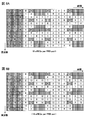
- an example of a method for mapping eCCEs in units of eREGs to a plurality of resource regions (here, PRB pairs) that can be used as ePDCCH will be described with reference to FIG.
- a case where 36 REs constituting an eCCE are defined 36 RE / 1 eCCE
- the size of the eCCE is not limited to this.
- the total number of eCCEs that can be used for downlink control information (DCI) transmitted using ePDCCH in the system band is the resource area ⁇ 4 arranged as ePDCCH.
- DCI downlink control information
- the number of eREGs constituting 1 eCCE can be obtained by “36 / (144 / N)”. That is, the value is obtained by dividing the number 36 of REs constituting 1 eCCE by the size of eREG (number of REs constituting 1 eREG). As described above, N corresponds to the number of eREGs provided in one resource region (for example, one PRB pair).
- the number of eREGs constituting one eCCE is two.
- the number of eREGs constituting one eCCE is 4.
- FIG. 9A shows four resource areas in which extended PDCCHs are arranged (here, PRB pairs # 1 to # 4), and each PRB pair and a plurality of eREGs when the number N of eREGs allocated to one PRB pair is 16.
- the relationship with (eREG index) is shown. That is, eREGs # 0 to # 15 are mapped to the PRB pairs # 1 to # 4.
- the REs constituting each of the eREGs # 0 to # 15 can be distributed and arranged in each PRB pair.
- the number of eCCEs allocated to one PRB pair is 4, the number of eREGs constituting one eCCE is 4.
- a plurality of eCCEs (here, 16 eCCEs # 0 to # 15) can be mapped to each PRB # 1 to # 4 as shown in FIG. 9B.
- mapping is performed so that a plurality of eREGs constituting one eCCE are distributed to different PRB pairs and the index numbers of the plurality of eREGs distributed to different PRB pairs are different. That is, a plurality of eREGs constituting one eCCE are mapped to different PRB pairs with different eREG index numbers attached thereto.
- a frequency diversity effect can be obtained by mapping a plurality of eREGs constituting one eCCE to different PRB pairs.
- 1 eCCE by configuring 1 eCCE with eREGs having different index numbers, it is possible to reduce non-uniform sizes between eCCEs.
- the eCCE index is mapped in order to the eREG index of a plurality of PRB pairs.
- mapping is performed so that eCCEs having consecutive index numbers are assigned to different PRB pairs. For example, as shown in FIG. 9B, eCCEs # 0 to # 3 are allocated to eREG # 0 allocated to PRB pairs # 1 to # 4. Similarly, eCCEs # 4 to # 7 are assigned to eREG # 1 assigned to PRB pairs # 1 to # 4. The same procedure is performed until a plurality of eCCEs complete a cycle. As a result, eCCEs # 0 to # 15 are assigned to eREGs # 0 to # 3 assigned to the PRB pairs # 1 to # 4.
- a cyclic shift is added and assigned in the same manner. For example, as shown in FIG. 9B, eCCEs # 0 to # 3 are allocated to eREG # 4 allocated to PRB pairs # 1 to # 4. However, in each eREG index, each eCCE is assigned in the order of PRB pairs # 2 to # 3, # 4, and # 1 (cyclic shift).
- a plurality of eCCEs can be mapped to each PRB pair in units of eREGs as shown in FIG. 9B.
- four eREGs constituting eCCE # 0 having an eCCE index number of 0 are distributed and allocated to PRBs # 1 to # 4, respectively.
- the four eREGs that make up eCCE # 0 are eREG # 0 (PRB pair # 1), eREG # 4 (PRB pair # 2), eREG # 8 (PRB pair # 3), eREG # 12 (PRB pair). # 4).
- mapping a plurality of eREGs constituting one eCCE to different PRB pairs with different eREG index numbers attached thereto it is possible to obtain a frequency diversity effect and to make the sizes of the eCCEs uniform.
- eREGs mapped to each PRB pair can be distributed and arranged in REs of a plurality of OFDM symbols in one PRB as shown in FIG. As a result, it is possible to improve the power utilization efficiency and to effectively equalize the size between eREGs and between eCCEs.
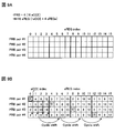
- a plurality of eREGs constituting one eCCE are mapped to different PRB pairs with different eREG index numbers.
- the total number of eCCEs (16 in FIG. 10A and 32 in FIG. 10B) is larger than the number of eREGs included in one PRB pair.
- the eCCE index is sequentially mapped to the eREG indexes of a plurality of PRB pairs, and as a result, eREGs of eCCEs having consecutive index numbers are assigned to different PRB pairs. .
- eREGs constituting eCCE # 0 and eCCE # 1 are mapped to different PRB pairs.
- two eREGs constituting eCCE # 0 are mapped to PRB pair # 1 (eREG # 0) and PRB pair # 3 (eREG # 4), and two eREGs constituting eCCE # 1 are mapped.
- eREG is mapped to PRB pair # 2 (eREG # 0) and PRB pair # 4 (eREG # 4).
- each frequency resource unit constituting the extended PDCCH set is described as being a PRB pair.
- Each frequency resource unit may be a PRB, or an RBG (Resource Block Group) composed of PRBs continuous in the frequency direction.
- FIG. 11 is an explanatory diagram of a system configuration of the wireless communication system according to the present embodiment.
- the radio communication system shown in FIG. 11 is a system including, for example, an LTE system or a successor system.
- carrier aggregation in which a plurality of fundamental frequency blocks with the system band of the LTE system as a unit is integrated is used.
- this wireless communication system may be called IMT-Advanced or 4G.
- the radio communication system 1 includes a radio base station 10 and a plurality of user terminals 20 that communicate with the radio base station 10.
- the radio base station 10 is connected to the upper station apparatus 30, and the upper station apparatus 30 is connected to the core network 40.
- the wireless base stations 10 are connected to each other by wired connection or wireless connection.
- Each user terminal 20 (20A, 20B) can communicate with the radio base station 10 in the cells C1, C2.
- the upper station device 30 includes, for example, an access gateway device, a radio network controller (RNC), a mobility management entity (MME), and the like, but is not limited thereto.
- RNC radio network controller
- MME mobility management entity
- Each user terminal 20 includes an LTE terminal and an LTE-A terminal.
- the user terminal 20 will be described as a user terminal unless otherwise specified.
- OFDMA Orthogonal Frequency Division Multiple Access
- SC-FDMA Single Carrier-Frequency Division Multiple Access
- the wireless access method is not limited to this.
- OFDMA is a multi-carrier transmission scheme that performs communication by dividing a frequency band into a plurality of narrow frequency bands (subcarriers) and mapping data to each subcarrier.
- SC-FDMA is a single carrier transmission method that reduces interference between terminals by dividing a system band into bands each consisting of one or continuous resource blocks for each terminal, and a plurality of terminals using different bands. .
- the downlink communication channel includes PDSCH (Physical Downlink Shared Channel) as a downlink data channel shared by each user terminal 20, a downlink L1 / L2 control channel (PDCCH, PCFICH, PHICH), and an extended PDCCH obtained by extending PDCCH. And have.
- PDSCH Physical Downlink Shared Channel
- PDSCH and PUSCH scheduling information and the like are transmitted by PDCCH (Physical Downlink Control Channel).
- the number of OFDM symbols used for PDCCH is transmitted by PCFICH (Physical Control Format Indicator Channel).
- the HARQ ACK / NACK for PUSCH is transmitted by PHICH (Physical Hybrid-ARQ Indicator Channel).
- the extended PDCCH is used to support a lack of PDCCH capacity using a resource region to which the PDSCH is allocated.
- the uplink communication channel has PUSCH (Physical Uplink Shared Channel) as an uplink data channel shared by each user terminal and PUCCH (Physical Uplink Control Channel) as an uplink control channel. User data and higher control information are transmitted by this PUSCH. Also, downlink radio quality information (CQI: Channel Quality Indicator), ACK / NACK, and the like are transmitted by PUCCH.
- PUSCH Physical Uplink Shared Channel
- PUCCH Physical Uplink Control Channel
- FIG. 12 is an overall configuration diagram of the radio base station 10 according to the present embodiment.
- the radio base station 10 includes a plurality of transmission / reception antennas 101 for MIMO transmission, an amplifier unit 102, a transmission / reception unit 103, a baseband signal processing unit 104, a call processing unit 105, and a transmission path interface 106. Yes.
- User data transmitted from the radio base station 10 to the user terminal 20 via the downlink is input from the higher station apparatus 30 to the baseband signal processing unit 104 via the transmission path interface 106.
- the baseband signal processing unit 104 performs PDCP layer processing, user data division / combination, RLC layer transmission processing such as RLC (Radio Link Control) retransmission control transmission processing, MAC (Medium Access Control) retransmission control, for example, HARQ transmission processing, scheduling, transmission format selection, channel coding, Inverse Fast Fourier Transform (IFFT) processing, and precoding processing are performed and transferred to each transceiver 203.
- RLC layer transmission processing such as RLC (Radio Link Control) retransmission control transmission processing, MAC (Medium Access Control) retransmission control, for example, HARQ transmission processing, scheduling, transmission format selection, channel coding, Inverse Fast Fourier Transform (IFFT) processing, and precoding processing are performed and transferred to each transceiver 203.
- RLC layer transmission processing such as RLC (Radio Link Control) retransmission control transmission processing, MAC (Medium Access Control) retransmission control, for example, HARQ transmission processing, scheduling, transmission format selection, channel coding, Inverse
- the baseband signal processing unit 104 notifies the control information for communication in the cell to the user terminal 20 through the broadcast channel.
- the information for communication in the cell includes, for example, the system bandwidth in the uplink or the downlink.
- Each transmission / reception unit 103 converts the baseband signal output by precoding from the baseband signal processing unit 104 for each antenna to a radio frequency band.
- the amplifier unit 102 amplifies the frequency-converted radio frequency signal and transmits the amplified signal using the transmission / reception antenna 101.
- radio frequency signals received by the respective transmission / reception antennas 101 are amplified by the amplifier units 102 and frequency-converted by the respective transmission / reception units 103. It is converted into a baseband signal and input to the baseband signal processing unit 104.
- the baseband signal processing unit 104 performs FFT processing, IDFT processing, error correction decoding, MAC retransmission control reception processing, RLC layer, and PDCP layer reception processing on user data included in the input baseband signal.
- the data is transferred to the higher station apparatus 30 via the transmission path interface 106.
- the call processing unit 105 performs call processing such as communication channel setting and release, status management of the radio base station 10, and radio resource management.
- FIG. 13 is an overall configuration diagram of the user terminal 20 according to the present embodiment.
- the user terminal 20 includes a plurality of transmission / reception antennas 201 for MIMO transmission, an amplifier unit 202, a transmission / reception unit (reception unit) 203, a baseband signal processing unit 204, and an application unit 205.
- radio frequency signals received by a plurality of transmission / reception antennas 201 are each amplified by an amplifier unit 202, converted in frequency by a transmission / reception unit 203, and converted into a baseband signal.
- the baseband signal is subjected to FFT processing, error correction decoding, retransmission control reception processing, and the like by the baseband signal processing unit 204.
- downlink user data is transferred to the application unit 205.
- the application unit 205 performs processing related to layers higher than the physical layer and the MAC layer. Also, broadcast information in the downlink data is also transferred to the application unit 205.
- uplink user data is input from the application unit 205 to the baseband signal processing unit 204.
- transmission processing for retransmission control H-ARQ (Hybrid ARQ)
- channel coding precoding
- DFT processing IFFT processing
- the like are performed and transferred to each transmission / reception unit 203.
- the transmission / reception unit 203 converts the baseband signal output from the baseband signal processing unit 204 into a radio frequency band.
- the amplifier unit 202 amplifies the frequency-converted radio frequency signal and transmits the amplified signal using the transmission / reception antenna 201.
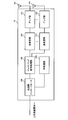
- FIG. 14 is a functional configuration diagram of the baseband signal processing unit 104 and some upper layers included in the radio base station 10 according to the present embodiment. Although FIG. 14 mainly shows a functional configuration for downlink (transmission), the radio base station 10 may include a functional configuration for uplink (reception).
- the radio base station 10 includes an upper layer control information generation unit 300, a data generation unit 301, a channel encoding unit 302, a modulation unit 303, a mapping unit 304, a downlink control information generation unit 305, common control information.
- the higher layer control information generation unit 300 generates higher layer control information for each user terminal 20.
- the upper layer control information is control information that is subjected to upper layer signaling (for example, RRC signaling), and includes, for example, extended PDCCH set allocation information (described later).
- the data generation unit 301 generates downlink user data for each user terminal 20.
- the downlink user data generated by the data generation unit 301 and the upper layer control information generated by the upper layer control information generation unit 300 are input to the channel encoding unit 302 as downlink data transmitted by the PDSCH.
- the channel coding unit 302 performs channel coding on the downlink data for each user terminal 20 according to a coding rate determined based on feedback information from each user terminal 20.
- the modulation unit 303 modulates the channel-coded downlink data according to a modulation scheme determined based on feedback information from each user terminal 20.
- the mapping unit 304 maps the modulated downlink data according to the instruction from the scheduling unit 317.
- the downlink control information generation unit 305 generates UE-specific downlink control information (DCI) for each user terminal 20.
- UE-specific downlink control information includes PDSCH allocation information (DL assignment), PUSCH allocation information (UL grant), and the like.
- the common control information generation unit 306 generates cell-specific common control information.
- the downlink control information generated by the downlink control information generation unit 305 and the common control information generated by the common control information generation unit 306 are input to the channel coding unit 307 as downlink control information transmitted on the PDCCH or the extended PDCCH.
- the Downlink control information transmitted in PDCC can be generated in units of control channel elements (CCE), and downlink control information transmitted in extended PDCCH can be generated in units of extended control channel elements (eCCE). Note that the CCE and eCCE sizes (number of REs) may be different or the same.
- the channel coding unit 307 channel-codes the input downlink control information according to the coding rate instructed from the scheduling unit 317.
- Modulation section 308 modulates the channel-coded downlink control information according to the modulation scheme instructed from scheduling section 317.
- downlink control information transmitted on the PDCCH is input from the modulation unit 308 to the control channel multiplexing unit 309 and multiplexed.
- the downlink control information multiplexed by the control channel multiplexing unit 309 is interleaved by the interleaving unit 310.
- the interleaved downlink control information is input to the IFFT unit 312 together with the measurement reference signal (CSI-RS: Channel State Information-Reference Signal, CRS: Cell specific Reference Signal, etc.) generated by the measurement reference signal generation unit 311. Is done.
- CSI-RS Channel State Information-Reference Signal
- CRS Cell specific Reference Signal, etc.
- mapping unit 313 maps the downlink control information in a predetermined allocation unit (for example, eREG unit) according to the instruction from the scheduling unit 317.
- the mapping unit 313 performs distributed mapping on the eCCE to which downlink control information is allocated for each resource region set for the extended PDCCH.
- the mapping unit 313 can also switch between distributed mapping and local mapping (Localized Mapping).
- the mapping unit 313 distributes a plurality of eREGs constituting one eCCE to a plurality of resource regions (PRB pairs or RBGs) in which extended PDCCHs are arranged, and to each resource region. Mapping is performed so that the index numbers of the eREGs differ. For example, as shown in FIG. 9, a plurality of eREGs constituting one eCCE are assigned different eREG index numbers and mapped to different PRB pairs, thereby obtaining a frequency diversity effect and the size of the eCCEs. Uniformity can be achieved.
- the mapping unit 313 can disperse and arrange eREGs mapped to each PRB pair in the REs of a plurality of OFDM symbols in one PRB. As a result, it is possible to improve the power utilization efficiency and to effectively equalize the size between eREGs and between eCCEs.
- the position (resource area) where the eREGs constituting each eCCE are mapped, the index number of the eREGs constituting each eCCE, the RE pattern corresponding to each eREG in the resource area, and the like are based on information from the scheduling unit 317. It may be set or determined in advance according to the specification.
- the mapped downlink control information includes downlink data transmitted on the PDSCH (that is, downlink data mapped by the mapping unit 304), and a demodulation reference signal (DM-RS) generated by the demodulation reference signal generation unit 314. At the same time, it is input to the weight multiplier 315.
- Weight multiplying section 315 multiplies downlink data transmitted by PDCSH, downlink control information transmitted by enhanced PDCCH, and a demodulation reference signal by a precoding weight specific to user terminal 20, and performs precoding.
- the precoded transmission data is input to the IFFT unit 312 and converted from a frequency domain signal to a time-series signal by inverse fast Fourier transform.
- a cyclic prefix (CP) functioning as a guard interval is inserted by the CP insertion unit 316 into the output signal from the IFFT unit 312 and output to the transmission / reception unit 103.
- the scheduling unit 317 schedules downlink data transmitted on the PDSCH, downlink control information transmitted on the enhanced PDCCH, and downlink control information transmitted on the PDCCH.
- the scheduling unit 317 includes CSI (Channel State Information) including instruction information from the upper station device 30 and feedback information from each user terminal 20 (for example, CQI (Channel Quality Indicator), RI (Rank Indicator), etc.). ) Etc.), radio resources are allocated.
- CSI Channel State Information
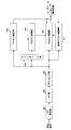
- FIG. 15 is a functional configuration diagram of the baseband signal processing unit 204 included in the user terminal 20.
- 15 mainly shows a functional configuration for downlink (reception), but the user terminal 20 may have a functional configuration for uplink (transmission).
- the user terminal 20 includes a CP removing unit 401, an FFT unit 402, a demapping unit 403, a deinterleaving unit 404, a PDCCH demodulating unit 405, a PDSCH demodulating unit 406, an extended PDCCH demodulating unit 407, a channel estimating unit, as a functional configuration for downlink. 408.
- the cyclic prefix (CP) is removed from the downlink signal received as reception data from the radio base station 10 by the CP removal unit 401.
- the downlink signal from which the CP is removed is input to the FFT unit 402.
- the FFT unit 402 performs fast Fourier transform (FFT) on the downlink signal to convert the signal in the time domain to the signal in the frequency domain, and inputs the signal to the demapping unit 403.
- the demapping unit 403 demaps the downlink signal. Note that the demapping process by the demapping unit 403 is performed based on higher layer control information input from the application unit 205.
- the downlink control information output from the demapping unit 403 is deinterleaved by the deinterleaving unit 404.
- the PDCCH demodulation unit 405 performs blind decoding, demodulation, channel decoding, and the like of downlink control information (DCI) output from the deinterleaving unit 404 based on the channel estimation result by the channel estimation unit 408. Specifically, PDCCH demodulation section 405 performs blind decoding on a search space candidate notified in advance from radio base station 10 or a predetermined search space candidate, and acquires downlink control information.
- DCI downlink control information
- the PDSCH demodulation unit 406 performs demodulation, channel decoding, and the like of the downlink data output from the demapping unit 403 based on the channel estimation result by the channel estimation unit 408. Specifically, the PDSCH demodulator 406 receives the PDSCH assigned to the terminal based on the downlink control information demodulated by the PDCCH demodulator 405 or the extended PDCCH demodulator 407 (for example, downlink scheduling information such as DL grant). Demodulate and acquire downlink data (downlink user data and higher layer control information) addressed to the terminal itself.
- the extended PDCCH demodulation unit 407 performs blind decoding, demodulation, channel decoding, and the like of the extended PDCCH demodulation unit 407 output from the demapping unit 403 based on the channel estimation result by the channel estimation unit 408.
- the channel estimation unit 408 performs channel estimation using a demodulation reference signal (DM-RS), a measurement reference signal (CRS, CSI-RS), and the like.
- Channel estimation section 408 outputs a channel estimation result based on measurement reference signals (CRS, CSI-RS) to PDCCH demodulation section 405.
- channel estimation section 408 outputs the channel estimation result based on the demodulation reference signal (DM-RS) to PDSCH demodulation section 406 and enhanced PDCCH demodulation section 407.
- a beamforming gain can be obtained for the PDSCH and the extended PDCCH by demodulation using a demodulation reference signal (DM-RS) unique to the user terminal 20.
- DM-RS demodulation reference signal
- the radio base station 10 generates downlink control information for each extended control channel element (eCCE) and is arranged for the extended downlink control channel. Downlink control information is mapped to a plurality of resource areas in units of eREG.
- the radio base station 10 distributes a plurality of eREGs constituting one eCCE in a plurality of resource areas, and performs mapping so that the index numbers of the eREGs distributed in the resource areas are different.
- the radio base station 10 arranges eREGs mapped to each PRB pair in a distributed manner in REs of a plurality of OFDM symbols in one PRB. As a result, it is possible to improve the frequency diversity effect and the power utilization efficiency, and to effectively equalize the size between eREGs and between eCCEs.
Landscapes
- Engineering & Computer Science (AREA)
- Signal Processing (AREA)
- Computer Networks & Wireless Communication (AREA)
- Mobile Radio Communication Systems (AREA)
Priority Applications (4)
| Application Number | Priority Date | Filing Date | Title |
|---|---|---|---|
| MX2015000901A MX341721B (es) | 2012-07-23 | 2013-07-22 | Metodo de radiocomunicacion, sistema de radiocomunicacion y estacion de base de radio. |
| US14/416,155 US9491749B2 (en) | 2012-07-23 | 2013-07-22 | Radio communication method, radio communication system and radio base station |
| CN201380037956.2A CN104488342B (zh) | 2012-07-23 | 2013-07-22 | 无线通信方法、无线通信系统以及无线基站 |
| EP13823237.6A EP2876962B1 (en) | 2012-07-23 | 2013-07-22 | Wireless communications method, wireless communications system, and wireless base station |
Applications Claiming Priority (2)
| Application Number | Priority Date | Filing Date | Title |
|---|---|---|---|
| JP2012162819A JP5829987B2 (ja) | 2012-07-23 | 2012-07-23 | 無線通信方法、無線通信システム及び無線基地局 |
| JP2012-162819 | 2012-07-23 |
Publications (1)
| Publication Number | Publication Date |
|---|---|
| WO2014017440A1 true WO2014017440A1 (ja) | 2014-01-30 |
Family
ID=49997251
Family Applications (1)
| Application Number | Title | Priority Date | Filing Date |
|---|---|---|---|
| PCT/JP2013/069803 WO2014017440A1 (ja) | 2012-07-23 | 2013-07-22 | 無線通信方法、無線通信システム及び無線基地局 |
Country Status (7)
Cited By (2)
| Publication number | Priority date | Publication date | Assignee | Title |
|---|---|---|---|---|
| WO2016033962A1 (zh) * | 2014-09-05 | 2016-03-10 | 中兴通讯股份有限公司 | 一种信道复用的方法和装置 |
| WO2016163922A1 (en) * | 2015-04-10 | 2016-10-13 | Telefonaktiebolaget Lm Ericsson (Publ) | Radio access node, wireless device and methods performed therein |
Families Citing this family (32)
| Publication number | Priority date | Publication date | Assignee | Title |
|---|---|---|---|---|
| CA2860981C (en) * | 2012-01-13 | 2019-02-19 | Branislav Popovic | Method for generating and transmitting demodulation reference signals |
| JP5781028B2 (ja) * | 2012-07-23 | 2015-09-16 | 株式会社Nttドコモ | 無線通信方法、無線基地局、ユーザ端末及び無線通信システム |
| CN103718630A (zh) | 2012-08-02 | 2014-04-09 | 华为技术有限公司 | 增强型物理下行控制信道传输方法及设备 |
| WO2014019208A1 (zh) | 2012-08-02 | 2014-02-06 | 华为技术有限公司 | 传输控制信息的方法、装置及系统 |
| JPWO2014027409A1 (ja) * | 2012-08-15 | 2016-07-25 | 富士通株式会社 | 通信システム、無線基地局、無線端末および通信方法 |
| KR101562702B1 (ko) | 2012-09-14 | 2015-10-22 | 주식회사 케이티 | 송수신포인트의 제어 정보 전송 방법 및 그 송수신포인트, 단말의 제어 정보 수신 방법 및 그 단말 |
| KR101562694B1 (ko) * | 2012-09-18 | 2015-10-22 | 주식회사 케이티 | 송수신포인트의 제어 정보 전송 방법 및 그 송수신포인트, 단말의 제어 정보 수신 방법 및 그 단말 |
| WO2014046425A2 (en) | 2012-09-18 | 2014-03-27 | Kt Corporation | Transmission and reception of control information |
| CN104956749B (zh) | 2013-01-29 | 2019-08-16 | 太阳专利托管公司 | 基站、终端以及通信方法 |
| US10652768B2 (en) | 2015-04-20 | 2020-05-12 | Qualcomm Incorporated | Control channel based broadcast messaging |
| CN107005375B (zh) * | 2015-07-16 | 2021-01-29 | 华为技术有限公司 | 终端到终端数据传输方法及设备 |
| US9955484B2 (en) * | 2015-08-06 | 2018-04-24 | Nokia Technologies Oy | Position information based access to a shared radio access channel |
| US10594428B2 (en) * | 2016-03-31 | 2020-03-17 | Sony Corporation | Terminal device, base station device, and communication method |
| EP3446516B1 (en) * | 2016-04-21 | 2019-12-11 | Telefonaktiebolaget LM Ericsson (publ) | Extended base station identification code comprising a radio frequency color code |
| CN109076044A (zh) * | 2016-05-13 | 2018-12-21 | 富士通株式会社 | 资源映射方法、装置以及通信系统 |
| JP6987137B2 (ja) * | 2016-11-03 | 2021-12-22 | オッポ広東移動通信有限公司Guangdong Oppo Mobile Telecommunications Corp., Ltd. | 信号を伝送するための方法、端末装置及びネットワーク装置 |
| KR102261777B1 (ko) * | 2016-11-04 | 2021-06-08 | 텔레호낙티에볼라게트 엘엠 에릭슨(피유비엘) | 짧은 물리 다운링크 제어 채널(sPDCCH) 매핑 설계 |
| KR102431635B1 (ko) * | 2016-11-04 | 2022-08-12 | 삼성전자 주식회사 | 무선 셀룰라 통신 시스템에서 지연 감소를 위한 적응적 재전송 방법 및 장치 |
| AU2016431316B2 (en) | 2016-11-30 | 2022-03-17 | Guangdong Oppo Mobile Telecommunications Corp., Ltd. | Information transmission method, terminal apparatus, and network apparatus |
| JP7054389B2 (ja) * | 2017-01-20 | 2022-04-13 | 株式会社Nttドコモ | 端末、無線通信方法、基地局及びシステム |
| CN114745088B (zh) | 2017-02-03 | 2024-11-19 | 韦勒斯标准与技术协会公司 | 无线通信系统中的用户设备和其操作方法 |
| US11122552B2 (en) * | 2017-02-06 | 2021-09-14 | Apple Inc. | Downlink control signaling segmentation |
| EP3934153B1 (en) * | 2017-03-17 | 2024-12-18 | Panasonic Intellectual Property Corporation of America | Base station, terminal, and communication method |
| CN110190943A (zh) * | 2017-08-30 | 2019-08-30 | 中国信息通信研究院 | 一种下行控制信道的资源配置方法和装置 |
| WO2019049351A1 (ja) * | 2017-09-08 | 2019-03-14 | 株式会社Nttドコモ | ユーザ端末および無線通信方法 |
| US10652069B2 (en) * | 2017-10-26 | 2020-05-12 | Qualcomm Incorporated | Resource element group mapping for a downlink control channel |
| WO2019097702A1 (ja) * | 2017-11-17 | 2019-05-23 | 株式会社Nttドコモ | ユーザ端末及び無線通信方法 |
| EP3720212B1 (en) * | 2017-12-01 | 2023-10-04 | NTT DoCoMo, Inc. | User terminal and wireless communication method |
| WO2019168051A1 (ja) * | 2018-03-01 | 2019-09-06 | 株式会社Nttドコモ | ユーザ端末及び無線通信方法 |
| PT3823337T (pt) * | 2018-07-13 | 2024-03-11 | Ntt Docomo Inc | Equipamento de utilizador e estação base |
| US11212062B2 (en) | 2018-09-28 | 2021-12-28 | Qualcomm Incorporated | Limits on quantity of downlink control information (DCI) processed |
| CN111181666B (zh) * | 2018-11-12 | 2021-03-12 | 大唐移动通信设备有限公司 | 一种时频调整方法及装置 |
Family Cites Families (3)
| Publication number | Priority date | Publication date | Assignee | Title |
|---|---|---|---|---|
| KR100956828B1 (ko) * | 2008-11-13 | 2010-05-11 | 엘지전자 주식회사 | 반(半)-지속적 스케줄링의 비활성화를 지시하는 방법 및 이를 이용한 장치 |
| JP5906532B2 (ja) | 2012-03-15 | 2016-04-20 | シャープ株式会社 | 基地局装置、端末装置、通信方法および集積回路 |
| US9374813B2 (en) * | 2012-03-28 | 2016-06-21 | Lg Electronics Inc. | Method for allocating resources for downlink control channel in wireless communication system and device for same |
-
2012
- 2012-07-23 JP JP2012162819A patent/JP5829987B2/ja active Active
-
2013
- 2013-07-22 US US14/416,155 patent/US9491749B2/en active Active
- 2013-07-22 CN CN201380037956.2A patent/CN104488342B/zh active Active
- 2013-07-22 EP EP13823237.6A patent/EP2876962B1/en active Active
- 2013-07-22 WO PCT/JP2013/069803 patent/WO2014017440A1/ja active Application Filing
- 2013-07-22 PT PT13823237T patent/PT2876962T/pt unknown
- 2013-07-22 MX MX2015000901A patent/MX341721B/es active IP Right Grant
Non-Patent Citations (6)
| Title |
|---|
| "DCI multiplexing by eREG", 3GPP TSG-RAN WG1 RL-122001, 25 May 2012 (2012-05-25), XP050600293 * |
| "Mapping of ePDCCH to RE", 3GPP TSG-RAN WG1 #69 RL-122000, 25 May 2012 (2012-05-25), XP050600292 * |
| "Multiplexing of ePDCCH for different users", 3GPP TSG RAN WG1 MEETING #68BIS RL-121288, 30 March 2012 (2012-03-30), XP050599578 * |
| "Views on Resource Mapping for ePDCCH", 3GPP TSG RAN WG1 MEETING #69 RL-121977, 25 May 2012 (2012-05-25), XP050601030 * |
| 3RD GENERATION PARTNERSHIP PROJECT: "Requirements for Evolved UTRA and Evolved UTRAN", 3GPP TR 25.913 |
| See also references of EP2876962A4 |
Cited By (3)
| Publication number | Priority date | Publication date | Assignee | Title |
|---|---|---|---|---|
| WO2016033962A1 (zh) * | 2014-09-05 | 2016-03-10 | 中兴通讯股份有限公司 | 一种信道复用的方法和装置 |
| CN105471561A (zh) * | 2014-09-05 | 2016-04-06 | 中兴通讯股份有限公司 | 一种信道复用的方法和装置 |
| WO2016163922A1 (en) * | 2015-04-10 | 2016-10-13 | Telefonaktiebolaget Lm Ericsson (Publ) | Radio access node, wireless device and methods performed therein |
Also Published As
| Publication number | Publication date |
|---|---|
| EP2876962A1 (en) | 2015-05-27 |
| EP2876962A4 (en) | 2016-03-16 |
| CN104488342B (zh) | 2018-09-18 |
| MX341721B (es) | 2016-08-31 |
| JP2014023108A (ja) | 2014-02-03 |
| US20150181573A1 (en) | 2015-06-25 |
| JP5829987B2 (ja) | 2015-12-09 |
| CN104488342A (zh) | 2015-04-01 |
| PT2876962T (pt) | 2019-03-27 |
| MX2015000901A (es) | 2015-04-10 |
| EP2876962B1 (en) | 2019-02-13 |
| US9491749B2 (en) | 2016-11-08 |
Similar Documents
| Publication | Publication Date | Title |
|---|---|---|
| JP5829987B2 (ja) | 無線通信方法、無線通信システム及び無線基地局 | |
| JP5809103B2 (ja) | 無線基地局、ユーザ端末、無線通信システム及び無線通信方法 | |
| JP5771177B2 (ja) | 無線基地局、ユーザ端末、無線通信システム及び無線通信方法 | |
| JP6219018B2 (ja) | 無線基地局装置、ユーザ端末、無線通信システム及び無線通信方法 | |
| JP5554799B2 (ja) | 無線基地局装置、ユーザ端末、無線通信システム及び無線通信方法 | |
| CN103931126B (zh) | 无线基站装置、用户终端、无线通信系统和无线通信方法 | |
| JP5726819B2 (ja) | 復号方法、無線基地局、ユーザ端末及び無線通信システム | |
| JP6105693B2 (ja) | 無線通信方法、無線通信システム及び無線基地局 | |
| JP5898874B2 (ja) | ユーザ端末、無線基地局装置、無線通信システム及び無線通信方法 | |
| JP6068860B2 (ja) | 無線通信方法、無線基地局、ユーザ端末及び無線通信システム | |
| JP5793131B2 (ja) | 無線基地局、ユーザ端末、無線通信システム及び無線通信方法 | |
| JP6106725B2 (ja) | 無線基地局、ユーザ端末、無線通信システム及び無線通信方法 |
Legal Events
| Date | Code | Title | Description |
|---|---|---|---|
| 121 | Ep: the epo has been informed by wipo that ep was designated in this application |
Ref document number: 13823237 Country of ref document: EP Kind code of ref document: A1 |
|
| WWE | Wipo information: entry into national phase |
Ref document number: MX/A/2015/000901 Country of ref document: MX |
|
| WWE | Wipo information: entry into national phase |
Ref document number: 14416155 Country of ref document: US |
|
| NENP | Non-entry into the national phase |
Ref country code: DE |
|
| WWE | Wipo information: entry into national phase |
Ref document number: 2013823237 Country of ref document: EP |