WO2014017179A1 - 放射線画像検出装置、並びに放射線撮影システム及びその作動方法 - Google Patents
放射線画像検出装置、並びに放射線撮影システム及びその作動方法 Download PDFInfo
- Publication number
- WO2014017179A1 WO2014017179A1 PCT/JP2013/065668 JP2013065668W WO2014017179A1 WO 2014017179 A1 WO2014017179 A1 WO 2014017179A1 JP 2013065668 W JP2013065668 W JP 2013065668W WO 2014017179 A1 WO2014017179 A1 WO 2014017179A1
- Authority
- WO
- WIPO (PCT)
- Prior art keywords
- pixel
- measurement
- pixels
- grid
- radiation
- Prior art date
- Legal status (The legal status is an assumption and is not a legal conclusion. Google has not performed a legal analysis and makes no representation as to the accuracy of the status listed.)
- Ceased
Links
Images










Classifications
-
- H—ELECTRICITY
- H10—SEMICONDUCTOR DEVICES; ELECTRIC SOLID-STATE DEVICES NOT OTHERWISE PROVIDED FOR
- H10F—INORGANIC SEMICONDUCTOR DEVICES SENSITIVE TO INFRARED RADIATION, LIGHT, ELECTROMAGNETIC RADIATION OF SHORTER WAVELENGTH OR CORPUSCULAR RADIATION
- H10F39/00—Integrated devices, or assemblies of multiple devices, comprising at least one element covered by group H10F30/00, e.g. radiation detectors comprising photodiode arrays
- H10F39/80—Constructional details of image sensors
- H10F39/802—Geometry or disposition of elements in pixels, e.g. address-lines or gate electrodes
-
- A—HUMAN NECESSITIES
- A61—MEDICAL OR VETERINARY SCIENCE; HYGIENE
- A61B—DIAGNOSIS; SURGERY; IDENTIFICATION
- A61B6/00—Apparatus or devices for radiation diagnosis; Apparatus or devices for radiation diagnosis combined with radiation therapy equipment
- A61B6/42—Arrangements for detecting radiation specially adapted for radiation diagnosis
- A61B6/4291—Arrangements for detecting radiation specially adapted for radiation diagnosis the detector being combined with a grid or grating
-
- A—HUMAN NECESSITIES
- A61—MEDICAL OR VETERINARY SCIENCE; HYGIENE
- A61B—DIAGNOSIS; SURGERY; IDENTIFICATION
- A61B6/00—Apparatus or devices for radiation diagnosis; Apparatus or devices for radiation diagnosis combined with radiation therapy equipment
- A61B6/44—Constructional features of apparatus for radiation diagnosis
- A61B6/4429—Constructional features of apparatus for radiation diagnosis related to the mounting of source units and detector units
- A61B6/4452—Constructional features of apparatus for radiation diagnosis related to the mounting of source units and detector units the source unit and the detector unit being able to move relative to each other
-
- A—HUMAN NECESSITIES
- A61—MEDICAL OR VETERINARY SCIENCE; HYGIENE
- A61B—DIAGNOSIS; SURGERY; IDENTIFICATION
- A61B6/00—Apparatus or devices for radiation diagnosis; Apparatus or devices for radiation diagnosis combined with radiation therapy equipment
- A61B6/54—Control of apparatus or devices for radiation diagnosis
- A61B6/542—Control of apparatus or devices for radiation diagnosis involving control of exposure
-
- G—PHYSICS
- G01—MEASURING; TESTING
- G01T—MEASUREMENT OF NUCLEAR OR X-RADIATION
- G01T1/00—Measuring X-radiation, gamma radiation, corpuscular radiation, or cosmic radiation
- G01T1/02—Dosimeters
- G01T1/026—Semiconductor dose-rate meters
-
- G—PHYSICS
- G01—MEASURING; TESTING
- G01T—MEASUREMENT OF NUCLEAR OR X-RADIATION
- G01T1/00—Measuring X-radiation, gamma radiation, corpuscular radiation, or cosmic radiation
- G01T1/16—Measuring radiation intensity
- G01T1/1603—Measuring radiation intensity with a combination of at least two different types of detectors
-
- G—PHYSICS
- G01—MEASURING; TESTING
- G01T—MEASUREMENT OF NUCLEAR OR X-RADIATION
- G01T1/00—Measuring X-radiation, gamma radiation, corpuscular radiation, or cosmic radiation
- G01T1/29—Measurement performed on radiation beams, e.g. position or section of the beam; Measurement of spatial distribution of radiation
- G01T1/2914—Measurement of spatial distribution of radiation
- G01T1/2985—In depth localisation, e.g. using positron emitters; Tomographic imaging (longitudinal and transverse section imaging; apparatus for radiation diagnosis sequentially in different planes, steroscopic radiation diagnosis)
-
- H—ELECTRICITY
- H05—ELECTRIC TECHNIQUES NOT OTHERWISE PROVIDED FOR
- H05G—X-RAY TECHNIQUE
- H05G1/00—X-ray apparatus involving X-ray tubes; Circuits therefor
- H05G1/08—Electrical details
- H05G1/26—Measuring, controlling or protecting
- H05G1/28—Measuring or recording actual exposure time; Counting number of exposures; Measuring required exposure time
-
- H—ELECTRICITY
- H05—ELECTRIC TECHNIQUES NOT OTHERWISE PROVIDED FOR
- H05G—X-RAY TECHNIQUE
- H05G1/00—X-ray apparatus involving X-ray tubes; Circuits therefor
- H05G1/08—Electrical details
- H05G1/26—Measuring, controlling or protecting
- H05G1/30—Controlling
- H05G1/38—Exposure time
-
- H—ELECTRICITY
- H05—ELECTRIC TECHNIQUES NOT OTHERWISE PROVIDED FOR
- H05G—X-RAY TECHNIQUE
- H05G1/00—X-ray apparatus involving X-ray tubes; Circuits therefor
- H05G1/08—Electrical details
- H05G1/26—Measuring, controlling or protecting
- H05G1/30—Controlling
- H05G1/38—Exposure time
- H05G1/42—Exposure time using arrangements for switching when a predetermined dose of radiation has been applied, e.g. in which the switching instant is determined by measuring the electrical energy supplied to the tube
-
- H—ELECTRICITY
- H05—ELECTRIC TECHNIQUES NOT OTHERWISE PROVIDED FOR
- H05G—X-RAY TECHNIQUE
- H05G1/00—X-ray apparatus involving X-ray tubes; Circuits therefor
- H05G1/08—Electrical details
- H05G1/26—Measuring, controlling or protecting
- H05G1/30—Controlling
- H05G1/38—Exposure time
- H05G1/42—Exposure time using arrangements for switching when a predetermined dose of radiation has been applied, e.g. in which the switching instant is determined by measuring the electrical energy supplied to the tube
- H05G1/44—Exposure time using arrangements for switching when a predetermined dose of radiation has been applied, e.g. in which the switching instant is determined by measuring the electrical energy supplied to the tube in which the switching instant is determined by measuring the amount of radiation directly
-
- H—ELECTRICITY
- H10—SEMICONDUCTOR DEVICES; ELECTRIC SOLID-STATE DEVICES NOT OTHERWISE PROVIDED FOR
- H10F—INORGANIC SEMICONDUCTOR DEVICES SENSITIVE TO INFRARED RADIATION, LIGHT, ELECTROMAGNETIC RADIATION OF SHORTER WAVELENGTH OR CORPUSCULAR RADIATION
- H10F39/00—Integrated devices, or assemblies of multiple devices, comprising at least one element covered by group H10F30/00, e.g. radiation detectors comprising photodiode arrays
- H10F39/10—Integrated devices
- H10F39/12—Image sensors
- H10F39/15—Charge-coupled device [CCD] image sensors
- H10F39/151—Geometry or disposition of pixel elements, address lines or gate electrodes
-
- A—HUMAN NECESSITIES
- A61—MEDICAL OR VETERINARY SCIENCE; HYGIENE
- A61B—DIAGNOSIS; SURGERY; IDENTIFICATION
- A61B6/00—Apparatus or devices for radiation diagnosis; Apparatus or devices for radiation diagnosis combined with radiation therapy equipment
- A61B6/42—Arrangements for detecting radiation specially adapted for radiation diagnosis
- A61B6/4208—Arrangements for detecting radiation specially adapted for radiation diagnosis characterised by using a particular type of detector
- A61B6/4233—Arrangements for detecting radiation specially adapted for radiation diagnosis characterised by using a particular type of detector using matrix detectors
-
- A—HUMAN NECESSITIES
- A61—MEDICAL OR VETERINARY SCIENCE; HYGIENE
- A61B—DIAGNOSIS; SURGERY; IDENTIFICATION
- A61B6/00—Apparatus or devices for radiation diagnosis; Apparatus or devices for radiation diagnosis combined with radiation therapy equipment
- A61B6/58—Testing, adjusting or calibrating thereof
- A61B6/582—Calibration
- A61B6/585—Calibration of detector units
-
- H—ELECTRICITY
- H10—SEMICONDUCTOR DEVICES; ELECTRIC SOLID-STATE DEVICES NOT OTHERWISE PROVIDED FOR
- H10F—INORGANIC SEMICONDUCTOR DEVICES SENSITIVE TO INFRARED RADIATION, LIGHT, ELECTROMAGNETIC RADIATION OF SHORTER WAVELENGTH OR CORPUSCULAR RADIATION
- H10F39/00—Integrated devices, or assemblies of multiple devices, comprising at least one element covered by group H10F30/00, e.g. radiation detectors comprising photodiode arrays
- H10F39/10—Integrated devices
- H10F39/107—Integrated devices having multiple elements covered by H10F30/00 in a repetitive configuration, e.g. radiation detectors comprising photodiode arrays
-
- H—ELECTRICITY
- H10—SEMICONDUCTOR DEVICES; ELECTRIC SOLID-STATE DEVICES NOT OTHERWISE PROVIDED FOR
- H10F—INORGANIC SEMICONDUCTOR DEVICES SENSITIVE TO INFRARED RADIATION, LIGHT, ELECTROMAGNETIC RADIATION OF SHORTER WAVELENGTH OR CORPUSCULAR RADIATION
- H10F39/00—Integrated devices, or assemblies of multiple devices, comprising at least one element covered by group H10F30/00, e.g. radiation detectors comprising photodiode arrays
- H10F39/10—Integrated devices
- H10F39/12—Image sensors
- H10F39/18—Complementary metal-oxide-semiconductor [CMOS] image sensors; Photodiode array image sensors
- H10F39/189—X-ray, gamma-ray or corpuscular radiation imagers
Definitions
- the present invention relates to a radiation image detection apparatus that detects a radiation image via a grid, a radiation imaging system, and an operation method thereof.
- the X-ray imaging system includes an X-ray generation apparatus that generates X-rays and an X-ray imaging apparatus that captures an X-ray image formed by X-rays transmitted through a subject (patient).
- the X-ray generator includes an X-ray source that irradiates X-rays toward a subject, a control device that controls driving of the X-ray source, and an irradiation switch that instructs the control device to start X-ray irradiation. Yes.
- An X-ray imaging apparatus includes an X-ray image detection apparatus that detects an X-ray image by converting X-rays transmitted through each part of an object into an electrical signal, drive control of the X-ray image detection apparatus, storage of an X-ray image, It has a console for displaying.
- the X-ray image detection apparatus includes an image detection unit that converts an X-ray image into an electrical signal, a control unit that controls the image detection unit, and the like.
- an image detection unit a flat panel detector (FPD) in which a large number of pixels are two-dimensionally arranged in an imaging region is widely used.
- FPD flat panel detector
- Each pixel accumulates electric charges according to the X-ray dose (X-ray time integral value).
- the electric charge accumulated in each pixel is read out to a signal processing circuit via a switching element such as a TFT (Thin Film Transistor) after photographing.
- the charge of each pixel is converted into a voltage signal by a signal processing circuit and output as an X-ray image signal.
- a known X-ray image detection apparatus has an X-ray dose measurement function and an automatic exposure control (AEC) function (for example, Japanese Patent Application Laid-Open No. 07-201490).
- AEC automatic exposure control
- this X-ray image detection apparatus one or a plurality of measurement pixels for measuring the X-ray dose are provided in the imaging region of the image detection unit together with normal pixels (X-ray image detection pixels) for detecting an X-ray image. Has been placed.
- This measurement pixel is used as a dose measurement sensor for measuring the X-ray dose, and measures the X-ray dose by reading out the measurement signal at regular intervals and integrating the measurement signals.
- AEC function instructs the X-ray source to stop X-ray irradiation.
- target X-ray dose a preset irradiation stop threshold
- the general pixel and the measurement pixel are simply referred to as a pixel when collectively referred to.
- a pixel means an element having at least a conversion function for converting a small part of an X-ray image into electric charge.
- the measurement pixel has the same size or several times the size of the normal pixel, and is arranged at one place or a plurality of places in the photographing region.
- the measurement pixel is arranged instead of the normal pixel, or the normal pixel is changed to the measurement pixel by performing a simple modification.
- a large dose measurement sensor such as a conventional ion chamber.
- X-ray imaging scattered rays are generated when X-rays pass through the subject.
- a thin plate-like grid is often used.
- This grid is arranged between the subject and the X-ray image detection apparatus, preferably just before the X-ray image detection apparatus.
- the grid includes a moving grid that swings during X-ray imaging and a stationary grid that is stationary. Below, when it is not necessary to distinguish these, it is simply called a grid.
- the grid has, for example, a structure in which strip-shaped X-ray transmission layers and X-ray absorption layers extending in the pixel column direction are alternately and repeatedly arranged along the pixel row direction. Since the X-ray absorption layer absorbs X-rays transmitted through the subject, the image quality of the captured X-ray image deteriorates if the width is wide. Therefore, in general, the width of the X-ray absorption layer is, for example, about 1/5 to 1/3 of the width of the X-ray transmission layer.
- each measurement pixel Need to be calibrated.
- This calibration method of the measurement value is described in, for example, Japanese Patent Application Laid-Open No. 2004-166724.
- X-ray imaging is performed when a grid is used and when a grid is not used without placing a subject. From the two images thus obtained, the output signal of the measurement pixel (referred to as AEC pixel in Japanese Patent Application Laid-Open No. 2004-166724) is the same when the grid is used and when it is not used.
- a correction coefficient is obtained for each measurement pixel.
- the X-ray dose is calibrated by multiplying the output signal of the measurement pixel by a correction coefficient.
- the arrangement direction of the X-ray transmission layer and the X-ray absorption layer of the grid is orthogonal to the row direction of the pixels.
- the measurement pixel size is also about 100 ⁇ m to 200 ⁇ m.
- the width of the X-ray absorption layer is about 50 ⁇ m to 100 ⁇ m. Since the overlap with the X-ray absorption layer changes, the output signal varies greatly.
- M or () can be placed on any measurement pixel according to the relationship between the grid pitch and the measurement pixel size.
- the smaller the number M the greater the fluctuation range of the output signal of the measurement pixel.
- the number M is a relatively small value. Therefore, the output signal of the measurement pixel is particularly susceptible to the influence of the X-ray absorption layer, and the relative position between the grid and the measurement pixel. The problem of the measurement accuracy of the X-ray dose when there is a deviation appears.
- the influence of the X-ray absorption layer can be obtained from an image obtained by photographing a moving grid or a stationary grid while the subject is not present. According to the experiments of the present inventors, when the pixel value having a large pixel value is compared with the pixel having a small pixel value due to the influence of the X-ray absorption layer in the vicinity thereof, the influence of the X-ray absorption layer is It is known that the received pixel value drops about 20% in a certain grid.
- the displacement of the relative position between the grid and the measurement pixel occurs due to the variation in the mounting position of each component during manufacturing.
- the relative position shift between the grid and the measurement pixel is caused by the variation in the mounting position of the electronic cassette or the grid.
- the relative position of the grid and the measurement pixel may be shifted due to vibration or the like.
- the relative position shift between the grid and the measurement pixel occurs at the time of manufacturing, it is necessary to take a calibration image for each product, which requires time and effort for the preparation. Furthermore, considering the case where X-rays are incident obliquely on the imaging region, it is necessary to prepare a large number of images for calibration, which is difficult in practice. Therefore, even if a relative position between the measurement pixel (generally a dose measurement sensor) and the grid is shifted, the X-ray dose can be measured easily and accurately without using a large number of calibration images. It is desired.
- An object of the present invention is to provide a radiographic image detection apparatus, a radiographic imaging system, and an operating method thereof capable of performing accurate dosimetry even when a relative position between a dosimetry sensor and a grid is shifted. .
- the radiological image detection apparatus of the present invention can be used with a grid, and an image detection unit disposed behind the grid includes a plurality of pixels and a plurality of dose measurement sensors.
- Each dosimetry sensor is positioned so as to satisfy the following condition 1.
- Condition 1 When fG / fN ⁇ odd and the grid and the pixels are relatively shifted C times one pixel at a time in the second direction, the number of first dosimetry sensors at all times is within the range of the period C. More than the number of second dosimetry sensors.
- the first dosimetry sensor is a dosimetry sensor that is not located at a specific point where the maximum or minimum value of the output signal is obtained when a radiographic image of the grid is captured by the image detection unit.
- strip-shaped radiation transmission layers and radiation absorption layers extending in the first direction are perpendicular to the first direction at a grid pitch G in order to remove scattered radiation generated when radiation passes through the subject.
- a plurality are alternately formed in two directions.
- the plurality of pixels are for detecting a radiographic image of the subject, and are arranged at a pixel pitch ⁇ in the second direction, and accumulate charges so as to be able to be read out according to the radiation dose.
- a plurality of dosimetry sensors measure the arrival dose of radiation.
- the radiological image detection apparatus preferably includes a determination unit that determines a radiation irradiation state based on measurement values of at least one group of dose measurement sensors, and a control unit that performs control according to the determination result of the determination unit.
- the group of dose measurement sensors is at least a part of the plurality of dose measurement sensors, and is a number of dose measurement sensors arranged in the second direction and corresponding to the period C.
- the pixel has a normal pixel for detecting a radiation image and a measurement pixel that is the same size as the normal pixel and is used as a dose measurement sensor, and the normal pixel and the measurement pixel are mixed, It is preferable to arrange two-dimensionally in the first and second directions.
- the normal pixel and the measurement pixel are connected to a common signal processing circuit. During irradiation with radiation, the normal pixel accumulates electric charge, but the electric charge of the measurement pixel is taken out to the signal processing circuit.
- condition 2 When the grid and the pixels are relatively shifted by one pixel, the following conditional expression 1 or 2 is satisfied at all times.
- Conditional expression 1 When 2j ⁇ fG / fN ⁇ 2j + 1, Conditional expression 2: When 2j + 1 ⁇ fG / fN ⁇ 2j + 2, Where each symbol is as follows: Q: number of first measurement pixels with respect to one of the second measurement pixels, a: Radiation absorption rate for one radiation absorbing layer, M: the minimum value of the number of radiation absorbing layers projected on the measurement pixel, k: In all the times, an allowable range ( ⁇ k%) of variation in measurement values of a group of measurement pixels, j: integer.
- the allowable range k of variation is k ⁇ 5 or k ⁇ 2.5.
- the measurement pixel arrangement period Z is satisfied so as to satisfy the following conditional expression 3. Is preferably determined.
- positions of the group of measurement pixels may be irregular in addition to regular.
- condition 1 When condition 1 is satisfied, the pixel pitch ⁇ and the grid pitch G are preferably determined so as to satisfy any of the following conditional expressions 1 to 4.
- Conditional expression 1 fG / fN ⁇ 2/3
- Conditional expression 4 4/3 ⁇ fG / fN ⁇ 8/3
- Conditional expression 3 10/3 ⁇ fG / fN ⁇ 14/3
- Conditional expression 4 16/3 ⁇ fG / fN ⁇ 20/3
- condition 3 the position of the group of measurement pixels is determined so as to satisfy the following condition 3 as well.
- Condition 3 The number of first measurement pixels is the same at all times, and the number of second measurement pixels is the same at all times.
- the determination unit determines whether the total radiation dose obtained by integrating the radiation dose measured at each measurement pixel or an average value thereof has reached the target dose, and determines that the total radiation dose or the average value has reached the target dose. When this is done, it is preferable to perform automatic exposure control to stop radiation irradiation.
- the determination of the position of the group of measurement pixels defined for the second direction is also applied to the first direction.
- the image detection unit is an electronic cassette housed in a portable housing.
- the radiation imaging system of the present invention includes a radiation source that emits radiation toward a subject, a radiation source control device that controls driving of the radiation source, and the radiation image detection device according to claim 1.
- the operation method of the radiation imaging system of the present invention includes a radiation dose measurement step, a determination step, and a radiation irradiation step.
- the radiation dose measurement step the radiation dose is measured by at least one group of dose measurement sensors among the plurality of dose measurement sensors.
- the determination step it is determined whether the total radiation dose obtained by integrating the radiation doses measured by the group of dosimetry sensors or the average value thereof has reached the target dose.
- the radiation irradiation step when the total radiation dose or its average value reaches the target dose, the radiation source is stopped to stop the radiation irradiation.
- the number of the first dosimetry sensors that are not at the position of the singular point having the maximum value or the minimum value on the radiographic image obtained by photographing the grid is determined as the second dose measurement at the position of the singular point. Since the number of sensors is larger than the number of sensors, even when the positional relationship with the grid is deviated, fluctuations in the output of the dose measurement sensor can be suppressed, and accurate dose measurement can be performed.
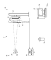
- the X-ray imaging system 2 includes an X-ray generation device 2a and an X-ray imaging device 2b.
- the X-ray generator 2a includes an X-ray source 10, a radiation source controller 11 that controls the operation of the X-ray source 10, and an irradiation switch 12 for instructing the start of X-ray irradiation.
- the X-ray imaging apparatus 2b removes the electronic cassette 13 that detects X-rays that have passed through the subject (patient) H and outputs an X-ray image, and scattered rays that are generated when the X-rays pass through the subject H.
- the electronic cassette 13 is used as a portable X-ray image detection device.
- a supine imaging stand for imaging the subject H in the supine posture
- a radiation source moving device (none of which is shown) and the like for setting the X-ray source 10 in a desired direction and position.
- the X-ray source 10 is shared by the standing and standing imaging tables.
- the X-ray source 10 includes an X-ray tube that emits X-rays and an irradiation field limiter (collimator) that limits an X-ray irradiation field.
- the X-ray tube has a cathode as a filament that emits thermoelectrons and an anode (target) that emits X-rays when the thermoelectrons emitted from the cathode collide.
- X-rays are irradiated in all directions from the point 10a where the thermoelectrons of the anode collide.
- the irradiation field limiter is, for example, one in which four lead plates that shield X-rays are arranged on each side of a square, and a rectangular irradiation opening that transmits X-rays is formed in the center. To adjust the irradiation field by changing the size of the irradiation aperture.
- the console 15 is communicably connected to the electronic cassette 13 by a wired method or a wireless method, and controls the operation of the electronic cassette 13 in accordance with an input operation from an operator such as a radiologist via an input device 15a such as a keyboard. To do.
- the X-ray image from the electronic cassette 13 is sent to the console 15 and displayed on the display 15b.
- the X-ray image is stored in a storage device or memory in the console 15 or a data storage such as an image storage server connected to the console 15 via a network.
- the console 15 displays on the display 15b an examination order including information such as the sex, age, imaging region, imaging purpose, etc. of the subject H.
- the examination order is input from an external system that manages patient information such as a hospital information system (HIS; Hospital Information System) or a radiation information system (RIS; Radiology Information System), or entered by an operator. Manually input from the device 15a.
- the examination order includes imaging parts such as the head, chest, and abdomen, front, side, oblique, PA (X-rays are irradiated from the back of the subject H), AP (X-rays are irradiated from the front of the subject H), etc.
- the shooting direction is included.
- the operator confirms the contents of the inspection order on the display 15b, and inputs photographing conditions corresponding to the contents of the inspection order through the operation screen on the display 15b.
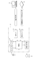
- the radiation source control device 11 includes a high voltage generator 20, a control unit 21, and a communication I / F 22.
- the high voltage generator 20 boosts the input voltage with a transformer to generate a high voltage tube voltage, and supplies it to the X-ray source 10 through a high voltage cable.
- the control unit 21 controls the tube voltage that determines the energy spectrum of X-rays irradiated by the X-ray source 10, the tube current that determines the irradiation amount per unit time, and the X-ray irradiation time.
- the communication I / F 22 mediates transmission / reception of main information and signals performed between the control unit 21 and the console 15.
- the irradiation switch 12, the memory 23, and the touch panel 24 are connected to the control unit 21.
- the irradiation switch 12 is, for example, a two-stage push switch operated by an operator.
- the irradiation switch 12 generates a warm-up start signal for starting the warm-up of the X-ray source 10 by one-stage push, and the X-ray source by two-stage push. 10 generates an irradiation start signal for starting X-ray irradiation.
- These signals are input to the control unit 21 through a signal cable.
- the control unit 21 When receiving the irradiation start signal from the irradiation switch 12, the control unit 21 causes the X-ray source 10 to start supplying power for X-ray irradiation from the high voltage generator 20.
- the memory 23 stores several types of imaging conditions such as tube voltage, tube current, irradiation time, or tube current irradiation time product (mAs value) depending on the region to be imaged.
- the shooting conditions are manually set by the operator through the touch panel 24.
- the radiation source control device 11 controls the tube voltage and tube current of the X-ray source 10 based on the set imaging conditions, and also controls the maximum drive time of the X-ray source 10.
- the AEC unit 54 measures the X-ray dose (time integral value), and when the target dose determined by the imaging region or the like is reached, the irradiation time or tube current based on the imaging conditions Even when the irradiation time product has not elapsed, the X-ray irradiation by the X-ray source 10 is stopped.
- the AEC unit 54 is used in order to prevent the X-ray irradiation from being terminated based on the imaging conditions before the AEC unit 54 stops the X-ray irradiation and thereby causing a shortage of dose, the AEC unit Compared to the case where 54 is not used, a larger value with a margin is set for the irradiation time or tube current irradiation time product of the imaging conditions. For example, as the irradiation time when the AEC unit 54 is used, the maximum irradiation time determined in safety regulations according to the imaging region may be used.
- the irradiation signal I / F 25 is wired or wirelessly connected to the electronic cassette 13 when the AEC unit 54 is used.
- the control unit 21 when receiving a warm-up start signal from the irradiation switch 12, the control unit 21 sends an irradiation start request signal for inquiring whether to start X-ray irradiation via the irradiation signal I / F 25. 13 to send.
- the electronic cassette 13 receives the irradiation start request signal, the electronic cassette 13 checks whether or not the photographing is possible, and transmits the irradiation permission signal if the photographing is possible.
- the control unit 21 receives the irradiation permission signal via the irradiation signal I / F 25, and supplies high voltage power from the high voltage generator 20 to the X-ray source 10 when receiving the irradiation start signal from the irradiation switch 12. X-ray irradiation is started. In addition, when the irradiation stop signal from the electronic cassette 13 is received via the irradiation signal I / F 25, the control unit 21 stops the power supply from the high voltage generator 20 to the X-ray source 10, thereby X-ray irradiation is stopped.
- the electronic cassette 13 includes an image detection unit 30 and a portable box-shaped casing 31 that accommodates the image detection unit 30.
- a known flat panel detector (FPD) is used as the image detection unit 30.
- the housing 31 is formed of, for example, a conductive resin, and a rectangular opening is formed in the front surface 31a on which X-rays are incident.
- a top plate 32 made of a material having high X-ray permeability is attached to the housing 31 so as to close the opening.
- the top plate 32 is made of a material that is lightweight, has high rigidity, and high X-ray permeability, such as a carbon material.
- the housing 31 has a function of an electromagnetic shield that prevents electromagnetic noise from entering the electronic cassette 13 and radiating electromagnetic noise from the electronic cassette 13 to the outside.
- the housing 31 houses a battery (secondary battery) that supplies power for driving the electronic cassette 13, an antenna for wireless communication of data such as an X-ray image with the console 15, and the like. Yes.
- the housing 31 conforms to the international standard ISO 4090: 2001 regarding film cassettes, IP cassettes, and CR cassettes, and has the same size as these.
- the electronic cassette 13 is attached to the holder 16a (see FIG. 1) of the standing photographing table 16 or the holder of the standing photographing table so that the imaging region 41 (see FIG. 5) is held in a posture facing the X-ray source 10. Set detachably. And according to the imaging stand to be used, the X-ray source 10 is moved by the radiation source moving device attached to the ceiling of the imaging room or the like.
- the electronic cassette 13 can be used alone as it is placed on a stand where the subject is placed in a standing position or on a prone position, or placed on a bed where the subject H lies, or is held by the subject H itself. is there. Further, since the electronic cassette 13 is compatible with a film cassette, an IP cassette, and a CR cassette, it can be attached to an existing photographing table for a film cassette, an IP cassette, or a CR cassette.
- the grid 14 is made of a thin plate having almost the same size as the casing 31.
- the grid 14 is detachably loaded in the holder 16a so as to be disposed in front of the electronic cassette 13 (see FIG. 1). Further, the grid 14 is replaced with another one according to the purpose of photographing, or is removed from the holder 16a in photographing without a grid.
- the holder 16a is not provided with a mechanism for swinging the grid 14, and thus the grid 14 is a so-called stationary grid that does not swing.
- the grid 14 is directly inserted into the holder 16a.
- the grid 14 is stored in an X-ray transmissive casing, and this casing is loaded in the holder 16a. Good.
- the grid 14 may be provided in the housing 31 when the electronic cassette 13 is manufactured.
- a grid holding part may be provided in the front surface 31a of the housing 31 of the electronic cassette 13, and the grid 14 may be detachably attached to the grid holding part.
- the grid 14 can be exchanged according to the imaging purpose, or X-ray imaging can be performed by removing the grid 14.
- the grid 14 has a strip-shaped X-ray transmission layer 35 and an X-ray absorption layer 36 (shown by hatching) extending in the Y1 direction (first direction), and each of these layers 35 and 36 has a predetermined grid pitch (X-ray absorption).
- This is a configuration in which a plurality of layers 36 are alternately arranged in the X1 direction (second direction) orthogonal to the Y1 direction at an arrangement pitch (G).
- the X-ray transmission layer 35 is formed of a material that easily transmits X-rays such as aluminum, or a gap.
- the X-ray absorption layer 36 is formed of a material such as lead, molybdenum alloy, or tantalum alloy that shields X-rays from being absorbed and not transmitted.
- the grid 14 is installed in the holder 16a so that the arrangement direction X1 of the layers 35 and 36 coincides with the row direction X2 (see FIG. 5) of the pixels 40 of the image detection unit 30.
- the number of X-ray absorption layers 36 per unit length in the arrangement direction X1 is, for example, 32 / cm to 100 / cm. Accordingly, the grid pitch G is 100 ⁇ m to about 300 ⁇ m.
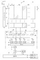
- the image detection unit 30 includes a TFT active matrix substrate (not shown), and an imaging region 41 is formed on the substrate.
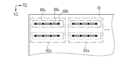
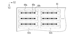
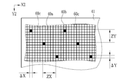
- an imaging region 41 a plurality of pixels 40 that generate charges according to the X-ray arrival dose are arranged in a matrix of n rows (X2 direction) ⁇ m columns (Y2 direction) at a predetermined pitch ⁇ (for example, 100 ⁇ m to 200 ⁇ m). Arranged in a shape.
- the image detection unit 30 is, for example, an indirect conversion type, has a scintillator (not shown) made of a phosphor, and photoelectrically converts visible light converted by the scintillator at the pixel 40.
- the scintillator is made of CsI: Tl (thallium activated cesium iodide), GOS (Gd 2 O 2 S: Tb, terbium activated gadolinium oxysulfide), or the like, and the imaging region 41 in which the pixels 40 are arranged. It is arranged to face the entire surface.
- the scintillator and the TFT active matrix substrate may be a PSS (Penetration Side Sampling) system in which the scintillator and the substrate are arranged in this order when viewed from the X-ray incident side, or conversely, the ISS (Irradiation) arranged in the order of the substrate and the scintillator. Side sampling) method may be used.
- the image detection unit 30 may be a direct conversion type using a conversion layer (such as amorphous selenium) that directly converts X-rays into electric charges without using a scintillator.
- the pixel 40 includes a photoelectric conversion unit that generates a charge (electron-hole pair) upon incidence of visible light, and a TFT (not shown) that is a switching element.
- the pixel pitch ⁇ represents the width of the pixels 40.
- the pixel pitch ⁇ is a distance between the centers of the photoelectric conversion units of two adjacent pixels 40.
- the pixel 40 includes a normal pixel 40a and a measurement pixel 40b.
- the normal pixel 40a is used for detecting an X-ray image, and charges accumulated after X-ray imaging is read out.
- the measurement pixel 40b is used for X-ray dose measurement, and charges are taken out during X-ray imaging.
- the measurement pixel 40b functions as a dose measurement sensor that measures the arrival dose of X-rays to the imaging region 41, and is used for AEC, for example.
- the measurement pixel 40b is hatched in order to distinguish it from the normal pixel 40a.
- the photoelectric conversion unit includes a semiconductor layer (for example, a PIN (p-intrinsic-n) type) that generates charges, and an upper electrode and a lower electrode that are disposed above and below the semiconductor layer.
- a TFT is connected to the lower electrode, and a bias line is connected to the upper electrode.
- bias lines are connected to a bias power source through a single bus.
- the gate electrode is connected to the scanning line 42, the source electrode is connected to the signal line 43, and the drain electrode is connected to the photoelectric conversion unit.
- the scanning lines 42 are wired in the row direction, and the signal lines 43 are wired in the column direction. Since one scanning line 42 is allocated to the pixels 40 for one row, the scanning lines 42 are provided for the number of rows of pixels 40 (n rows) in total. In addition, since one signal line 43 is provided for one column of pixels 40, a total of the number of columns of pixels 40 (m columns) is provided.
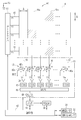
- Each scanning line 42 is connected to a gate driver 44, and each signal line 43 is connected to a signal processing circuit 45.
- the gate driver 44 drives the TFT under the control of the control unit 52 to accumulate the signal charge corresponding to the X-ray arrival dose in the normal pixel 40a, and the signal charge accumulated from the normal pixel 40a.
- a read (main reading) operation for reading and a reset (empty reading) operation are performed.
- the TFT is in an off state, and signal charges generated during that time are accumulated in the normal pixel 40a.
- the readout operation is performed immediately after X-ray imaging.
- gate pulses P1 to Pn are sequentially generated from the gate driver 44 at predetermined intervals, and the scanning lines 42 are sequentially activated row by row.
- the activated scanning line 42 turns on one row of TFTs connected thereto.
- the charge accumulated in the normal pixel 40a is read out to the signal line 43 and sent to the signal processing circuit 45 when the TFT is turned on.
- the measurement pixel 40b is used for measurement of X-ray dose, and the basic configuration of the photoelectric conversion unit and the like is the same as that of the normal pixel 40a.
- the source electrode and the drain electrode of the TFT are short-circuited. For this reason, the charge generated in the photoelectric conversion unit of the measurement pixel 40b flows out to the signal line 43 regardless of whether the TFT is on or off. Therefore, the signal charge of the measurement pixel 40b can be taken out even during the signal charge accumulation operation because the TFTs of the normal pixel 40a in the same column are in the OFF state.
- the signal processing circuit 45 includes an integrating amplifier 46, an amplifier 50, a CDS circuit (CDS) 47 provided for each signal line 43, a multiplexer (MUX) 48 commonly used for each signal line 43, and an A / D converter. (A / D) 49 is provided.
- the integrating amplifier 46 includes an operational amplifier 46a and a capacitor 46b connected between the input and output terminals of the operational amplifier 46a, and the signal line 43 is connected to one input terminal of the operational amplifier 46a. The other input terminal of the operational amplifier 46a is connected to the ground (GND).
- a reset switch 46c is connected in parallel to the capacitor 46b.
- the CDS 47 has a sample and hold circuit, performs correlated double sampling on the output voltage signal of the integration amplifier 46 to remove noise, and holds the voltage signal of the integration amplifier 46 for a predetermined period (sample hold) by the sample and hold circuit. To do. Based on an operation control signal from a shift register (not shown), the MUX 48 selects one CDS 47 in turn with an electronic switch for the CDSs 47 in each column connected in parallel. The voltage signal of the selected CDS 47 is serially input to the A / D 49. The A / D 49 converts the voltage signal into a digital voltage signal and outputs it to the memory 51 as image data for one row. An amplifier may be connected between the MUX 48 and the A / D 49.
- the integration amplifier 46 integrates the signal charges taken out from the normal pixels 40a in the activated row via the signal line 43 and converts them into analog voltage signals V1 to Vm.
- the voltage signals V1 to Vm of each integrating amplifier 46 are amplified by the amplifier 50 and then sent to the CDS 47.
- the voltage signals V1 to Vm from which noise has been removed by the CDS 47 are sequentially taken out by the MUX 48 and digitally converted by the A / D 49.
- the memory 51 records image data line by line in association with the coordinates of the normal pixel 40a.
- a dose measurement signal is sent to the memory 51 as a measurement value.
- new measurement values are updated and recorded every predetermined time in association with coordinate information of each measurement pixel 40b in the imaging region 41.
- a dark charge is generated in the semiconductor layer of the photoelectric conversion unit regardless of whether or not X-rays are incident. This dark charge is accumulated in the photoelectric conversion unit of each pixel 40 because a bias voltage is applied. Since the dark charge generated in the pixel 40 becomes a noise component for the image data, a reset operation is performed every predetermined time in order to remove it. The reset operation is an operation of sweeping out dark charges generated in the pixels 40 through the signal line 43.
- the reset operation is performed by, for example, a sequential reset method in which the pixels 40 are reset row by row.
- the sequential reset method similarly to the signal charge reading operation, gate pulses P1 to Pn are sequentially generated from the gate driver 44 to the scanning line 42 at a predetermined interval to turn on the TFTs of the pixels 40 one row at a time. . While the TFT is in the on state, dark charge flows from the pixel 40 to the capacitor 46 b of the integrating amplifier 46 through the signal line 43.
- the reset pulse RST is output from the control unit 52 in synchronization with the generation of the gate pulses P1 to Pn. 46c is turned on, the charge accumulated in the capacitor 46b is discharged, and the integrating amplifier 46 is reset.
- the sequential reset method instead of the sequential reset method, multiple rows of array pixels are grouped as a group, and the reset is performed sequentially within the group, and the dark charge of the number of groups is simultaneously swept away.
- An all-pixel reset method that simultaneously sweeps out the dark charges may be used.
- the parallel reset method and the all-pixel reset method can speed up the reset operation.
- the control unit 52 is provided with an image processing circuit (not shown) that performs various types of offset correction, sensitivity correction, and defect correction on the X-ray image data in the memory 51.
- the offset correction circuit subtracts the offset correction image acquired from the image detection unit 30 without irradiating the X-ray in units of pixels from the X-ray image, thereby fixing the fixed pattern noise due to individual differences in the signal processing circuit 45 and the imaging environment. Remove.
- the sensitivity correction circuit is also called a gain correction circuit, and corrects variations in sensitivity of the photoelectric conversion unit of each pixel 40, variations in output characteristics of the signal processing circuit 45, and the like.
- the defect correction circuit linearly interpolates the pixel value of the defective pixel with the pixel values of the surrounding normal pixels based on the defective pixel information generated at the time of shipment or regular inspection.
- the defect correction circuit also handles the measurement pixel 40b as a defective pixel. Since the pixel value of the normal pixel 40a in the column in which the measurement pixel 40b is arranged is also affected by the output of the measurement pixel 40b that always flows out, the defective pixel correction circuit arranges the pixel value of the measurement pixel 40b and the measurement pixel 40b.
- the defect correction is also performed by linear interpolation on the pixel value of the normal pixel 40a in the column. Note that the various image processing circuits described above may be provided in the console 15, and various image processing may be performed by the console 15.
- the control unit 52 reads the dose measurement signal (measurement value) measured this time and the cumulative measurement value (cumulative X dose) up to the previous time from the memory 51 for each X-ray dose measurement, and integrates each measurement pixel 40b. Then, a new accumulated measurement value is obtained, and this is overwritten in the memory 51.
- the AEC unit 54 takes out the accumulated measurement values of all or some of the measurement pixels 40b included in the daylighting field, and arithmetically averages them to obtain an average value (average accumulated X-ray dose). When the obtained average value reaches the irradiation stop threshold (target dose), an irradiation stop signal is generated.
- This irradiation stop signal is output from the irradiation signal I / F 55 via the control unit 52.
- the irradiation signal I / F 25 of the radiation source control device 11 is wired or wirelessly connected to the irradiation signal I / F 55.
- the irradiation signal I / F 55 receives an irradiation start request signal, transmits an irradiation permission signal in response to the irradiation start request signal, receives an irradiation start signal, and transmits an irradiation stop signal output from the AEC unit 54.
- the operation of the X-ray imaging system 2 will be described. Preparation for imaging is performed before X-ray imaging.
- the electronic cassette 13 is loaded in the holder 16a of the photographing stand, for example, the standing photographing stand 16.
- the grid 14 is loaded into the holder 16 a and placed in front of the electronic cassette 13.
- the touch panel or the like is operated to input imaging conditions such as tube voltage, tube current, irradiation time, and imaging region.
- an irradiation field is set according to the imaging region. For example, when the imaging part of the subject H is the chest, an area corresponding to the left and right lung fields in the imaging area 41 is set as the daylighting field.
- X-ray imaging can be performed.
- the electronic cassette 13 When the electronic cassette 13 is loaded in the holder 16a, it enters a standby mode. In this standby mode, dark charges are generated in each pixel 40 of the image detection unit 30 even when X-rays are not irradiated. In order to remove the dark charge, which is a noise component, during the preparation for X-ray imaging (before X-ray imaging), the image detection unit 30 is reset every predetermined time. In this reset operation, gate pulses P1 to Pn are sequentially generated from the gate driver 44 to the scanning line 42 to turn on the TFTs of the normal pixels 40a row by row. While the TFTs of each normal pixel 40a for one row are in the on state, dark charges accumulated in these normal pixels 40a are read out and sent to the integrating amplifier 46. In this reset operation, the voltage converted by the integrating amplifier 46 is not extracted by the MUX 48.
- the control unit 52 outputs a reset pulse RST with a predetermined time difference with respect to each of the gate pulses P1 to Pn. Since the reset switch 46c is turned on by the reset pulse RST, the dark charge accumulated in each capacitor 46b is discharged and the integrating amplifier 46 is reset. In the measurement pixel 40b, since the TFT is short-circuited, dark charges are sent to the integrating amplifier 46 regardless of the gate pulses P1 to Pn. Thereby, the dark charge from the measurement pixel 40b is discarded together with the dark charge of the normal pixel 40a. During the reset operation, the reset switch 46c may be kept on.
- the irradiation switch 12 After preparation for X-ray imaging, the irradiation switch 12 is pushed one step to warm up the X-ray source 10. Subsequently, the irradiation switch 12 is fully pressed to generate an irradiation start signal. This irradiation start signal is input to the control unit 21 of the radiation source control device 11 and X-ray imaging is started. The irradiation start signal is sent to the electronic cassette 13 through the irradiation signal I / F 25. The electronic cassette 13 is switched from the standby mode to the photographing mode, and the image detection unit 30 shifts from the reset operation to the accumulation operation. At the same time, automatic exposure control based on the dose measurement of the measurement pixel 40b is started.
- the X-ray source 10 When the X-ray imaging is started, the X-ray source 10 is driven by the high voltage from the high voltage generator 20. The X-ray source 10 generates X-rays and irradiates the imaging region of the subject H. X-rays that have passed through this imaging region enter the grid 14. The grid 14 blocks X-rays that have entered the X-ray absorption layer 36, but X-rays that have entered the X-ray transmission layer 35 pass through this and enter the electronic cassette 13. X-rays incident on the electronic cassette 13 are converted into visible light by the image detection unit 30. This visible light is converted into electric charges by the photoelectric conversion unit of each pixel 40. During the accumulation operation of the image detection unit 30, since the TFT is in an off state, each normal pixel 40a accumulates the generated charges in the photoelectric conversion unit.
- each measurement pixel 40 b is accumulated in the capacitor 46 b of the corresponding integration amplifier 46.
- the reset switch 46c of each integrating amplifier 46 is normally turned off, but is turned on once every predetermined time to reset the integrating amplifier 46. A section in which the reset switch 46c is turned off after being turned on is one measurement section, and the X-ray dose per predetermined time is measured.
- X-rays are measured in a relatively short cycle, and the X-ray dose is measured for each measurement pixel 40b by integrating the measured values of each time.
- the voltage of each integrating amplifier 46 may be read out in a relatively short cycle while the reset switch 46c of the integrating amplifier 46 is kept in an off state. In this way, in each cycle, since the accumulated measurement value is taken out, it is not necessary to integrate the measurement values of each time.
- the output voltage of the integrating amplifier 46 is amplified by the amplifier 50 and then sent to the CDS 47.
- This CDS 47 samples the output voltage of the integrating amplifier 46 at the start and end of one measurement, and removes the noise by obtaining the difference.
- the output voltage of each CDS 47 is sequentially taken out by the MUX 48 and sent to the A / D 49. Then, it is digitally converted by the A / D 49 and sent to the memory 51 as a dose measurement signal per predetermined time.
- each dose measurement signal is recorded as a first measurement value in the first memory area in association with the coordinate information of the measurement pixel 40b.
- the AEC unit 54 selects the minimum unit of measurement pixels 40b (referred to as a group of measurement pixels 40b) that are included in the designated daylighting field and that can offset the influence of the positional deviation of the grid 14.
- the group of measurement pixels 40b may be a single measurement pixel 40b, or may be a plurality of measurement pixels 40b at different positions in the lighting field. Furthermore, all the measurement pixels 40b in the designated daylighting field may be selected measurement pixels used for automatic exposure control.
- the AEC unit 54 obtains an average value from the measurement values of each selected measurement pixel. Next, the AEC unit 54 compares the calculated average value with a preset irradiation stop threshold value. If the average value does not reach the irradiation stop threshold value, the second X-ray dose is measured in synchronization with the operation of the reset switch 46c. In addition, you may obtain
- the output voltage of the integrating amplifier 46 is taken out and sent to the memory 51 as the second measurement value, and is associated with the coordinate information of the measurement pixel 40b. , Recorded in the second memory area.
- the control unit 52 adds the second measurement value to the first measurement value in the first memory area in units of measurement pixels, and the obtained cumulative measurement value (cumulative X-ray dose)
- the measurement value in the first memory area is updated.
- the AEC unit 54 reads the accumulated measurement value of each selected measurement pixel from the first memory area and obtains an average value thereof.
- the AEC unit 54 compares the calculated average value with the irradiation stop threshold value. Even in the second measurement, when the average value does not reach the irradiation stop threshold, the third X-ray dose is measured by the above-described procedure.
- the AEC unit 54 determines that appropriate exposure has been performed. In this case, the control unit 52 sends an irradiation stop signal to the radiation source control device 11 via the irradiation signal I / F 55.
- the radiation source control device 11 stops the operation of the high voltage generator 20. Thereby, the X-ray source 10 stops the X-ray irradiation and ends the X-ray imaging.
- the image detection unit 30 starts a reading operation. At the start of this read operation, first, all reset switches 46c are turned on, and each integrating amplifier 46 is reset. Thereby, the electric charge from the measurement pixel 40b is discarded. Next, after all the reset switches 46c are turned off, the gate driver 44 generates the gate pulse P1 of the first row. This gate pulse P1 activates the scanning line 42 in the first row and turns on the TFT connected thereto. The charge accumulated in the normal pixels 40a in the first row is sent to the integrating amplifier 46 via the signal line 43 when the TFT is turned on. The signal charge of each pixel 40a is converted into a voltage by the integrating amplifier 46, and is recorded as X-ray image data for the first row in the memory 51 via the amplifier 50, CDS 47, MUX 48, and A / D 49.
- the control unit 52 When the image data for the first row is written in the memory 51, the control unit 52 outputs a reset pulse RST to the integrating amplifier 46, and turns on and off the reset switch 46c. As a result, the signal charge accumulated in each capacitor 46b is discharged. After resetting the integrating amplifier 46, the gate driver 44 outputs the gate pulse P2 in the second row and starts reading the signal charges of the normal pixels 40a in the second row. The X-ray image data of the second row obtained in this way is written into the memory 51.
- the gate driver 44 sequentially generates the third to nth gate pulses P3 to Pn, reads the charges of the normal pixels 40a in the third to nth rows, and reads the X-rays in the third to nth rows.
- the image data is converted and written into the memory 51.
- the X-ray image written in the memory 51 is subjected to various image processing such as offset correction, sensitivity correction, and defect correction by the control unit 52.
- offset correction fixed pattern noise caused by individual differences in the signal processing circuit 45 and the photographing environment is removed.
- sensitivity correction corrects variations in sensitivity of the photoelectric conversion units of the respective normal pixels 40a, variations in output characteristics of the signal processing circuit 45, and the like.
- defect correction linear interpolation is performed on defective pixels that have been examined in advance, or normal pixels 40a in a column in which the measurement pixels 40b and the measurement pixels 40b are arranged, using the surrounding pixel values.
- the X-ray image in the memory 51 subjected to the image processing is sent from the electronic cassette 13 to the console 15 via the communication I / F 53.
- this console 15 an X-ray image is displayed on the display 15b and used for medical diagnosis.
- the X-ray image sent to the console 15 is stored in a storage device in the console 15 or an image storage server connected to the console 15 via a network.
- ⁇ Shooting without a grid is the same as shooting with a grid except that the grid 14 is removed from the photographic stand. Further, in imaging without a grid, all of the measurement pixels 40b do not receive X-ray absorption by the grid 14, so that the dose measurement signal is larger than in imaging with a grid. Therefore, the irradiation stop threshold value (target dose) for imaging without grid is set larger than the irradiation stop threshold value (target dose) for imaging with grid, and the X-ray irradiation amount of the subject H in imaging with grid and imaging without grid (Exposure dose) is the same.
- the irradiation stop signal is generated when the average value of the accumulated measurement values of each measurement pixel 40b reaches the irradiation stop threshold. Instead, the time predicted to reach the target dose is calculated from the X-ray intensity (X dose per unit time), and when the calculated predicted time is reached, an irradiation stop signal is generated to generate the radiation source control device 11. May be sent to. Even if the X-ray emission of the X-ray source 10 is stopped when the prediction time information itself is transmitted to the radiation source control device 11 and it is detected that the prediction time has passed. Good.
- pre-imaging that irradiates the subject with a low dose of X-rays may be performed, and the irradiation time or tube current irradiation time product of the main X-ray imaging may be determined based on the measurement of the X-ray dose in the pre-imaging.
- the electronic cassette 13 and the grid 14 may be set on the photographing stand in a state deviated from the design positional relationship.
- the positional relationship may change due to vibration or the like during loading on the photographing stand.
- the arrangement of the measurement pixels is devised so that even if the positional relationship between the electronic cassette 13 and the grid 14 is deviated, fluctuations in the measurement values of the measurement pixels are reduced so that dose measurement is not affected. is there.
- an example of the arrangement of the measurement pixels that can reduce the variation of the measurement value will be described.
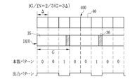
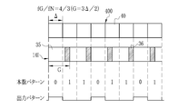
- the pixel arrays shown in FIGS. 6 to 12 are obtained by extracting one row of the pixels 40 from the image detecting unit 30 shown in FIG. 5 and drawing a part thereof.
- the reference numeral “400” is assigned to the pixel array
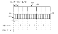
- the reference numeral “40” is assigned to the pixels as in FIG. 6 to 12 show the positional relationship between each pixel 40 and the X-ray absorption layer 36 when the grid pitch G and the pixel pitch ⁇ are variously changed, and the respective layers 35 and 36 in the state where the subject H does not exist.
- the pattern of the number of X-ray absorption layers 36 projected on the pixels 40 (hereinafter referred to as the number pattern) when the image of the striped grid 14 corresponding to is taken, and each pixel that changes depending on the positional relationship and the number pattern A voltage signal pattern (hereinafter referred to as an output pattern) measured at 40 is shown.
- the pixel 401 at the left end does not face the X-ray absorption layer 36, and thus the number of X-ray absorption layers 36 projected onto the pixel 401 is zero.
- the pixel 402 on the right side faces one X-ray absorption layer 36, the number of X-ray absorption layers 36 projected onto the pixel 402 is one.
- the number of X-ray absorption layers 36 projected onto the pixels 40 is zero and one pixel is alternately repeated.
- the single pixel 40 has a relatively smaller cumulative X-ray dose than the zero pixel, and therefore the output level of the voltage signal is also relatively low. For this reason, the output pattern has a voltage signal “high” having a relatively high output level and a voltage signal “low” having a low output level repeated in a cycle of two pixels.
- FIG. 6B is wider than the grid 14A in FIG. 6A (Wb> Wa), so FIG. 6B is more in number than FIG. 6A.
- the voltage signal of one pixel 40 becomes low. Therefore, in FIG. 6B, the difference between the “high” and “low” voltage signals is larger than that in FIG.
- the width Wb of the X-ray absorption layer 36 is equal to or smaller than the pixel pitch ⁇ as in FIG. 6A, the number of the X-ray absorption layers 36 projected onto the pixels 40 in the case of FIG.
- the cycle repeats 0 and 1 and the output pattern repeats “high” and “low” every two pixels.
- the X-ray absorption layer 36 is projected onto two adjacent pixels 40 at the same time.
- the pixel 401 on the left end faces a part of one X-ray absorption layer 36, for example, 0.3.
- the pixel 402 on the right side faces the remaining 0.7 pixels.
- the pixel 402 facing 0.7 of the X-ray absorption layer 36 has a relatively lower X-ray dose than the pixel 401 facing 0.3, and therefore the voltage signal is also relatively low. Become.
- the output pattern repeats “high” and “low” in a two-pixel cycle.
- FIG. 6C is the same as FIG. 6A and FIG. 6B in that the number of X-ray absorption layers 36 projected onto the pixel 40 is repeated in a two-pixel cycle when the number is small and large. The same applies to the point that the output pattern repeats “high” and “low” in a two-pixel cycle.
- the grid pitch G and the pixel pitch ⁇ are constant for the entire row, so that the pixel 40 is shifted by one pixel in the row direction X2 relative to the grids 14A to 14C.
- the number pattern and the output pattern do not change only by shifting one pixel 40 facing the X-ray absorption layer 36. This is the same no matter how many pixels are shifted. Even if the number or output level itself is changed even if it is shifted by an amount of 1 pixel or less such as 0.5 pixel instead of 1 pixel, the number pattern “0”, “1” and the output pattern “high”, The periodicity of the peak formed at “low” is the same as before shifting.
- the grid 14D in FIG. 7A and the grid 14E in FIG. 7B have different widths Wd and We of the X-ray absorption layer 36, but these widths We and Wd are adjacent to the X-ray absorption layer 36. It is set to a value that is not projected onto the pixels 40 at the same time.
- these grids 14D and 14E are used, pixels on which one X-ray absorption layer 36 is projected and pixels on which two X-ray absorption layers 36 are projected are alternately arranged. Therefore, in both FIGS. 7A and 7B, the number pattern is “1, 2, 1, 2,...”.
- the output pattern is “high, low, high, low,...”, Which is the same as in the case of FIG.
- the grids 14D and 14E have a width that does not cover the two pixels of the X-ray absorption layer 36. However, even when the X-ray absorption layer 36 is as wide as two pixels, the change in the number pattern and the periodicity of the peak of the output pattern are shown in FIG. Is the same as
- the periodicity of the peak is important in the present invention, in the following description, an example in which the relative position of the grid 14 and the pixel 40 is a certain position and the width of the X-ray absorption layer 36 is a certain width will be given. However, since the periodicity of the peak does not change even if the relative position of the grid 14 and the pixel 40 or the width of the X-ray absorption layer 36 varies as described above, the present invention can be applied to other than the above examples. Regarding the fluctuation of the number itself, the effect will be described last.
- the number sequence of the number pattern has a period of two pixels.
- the number M increases to 0, 1, 2, 3,... As the odd number increases to 1, 3, 5, 7,.
- the output pattern is “high, low, high, low,...”.
- the number pattern is “1, 1, 1, 1,...”, And the number of X-ray absorption layers 36 projected on each pixel 40 does not change.
- the voltage signal has a constant value without undulations.
- the positional relationship with the absorption layer 36, the number pattern and the output pattern are shown.
- a grid 14H is used, the number pattern is “0, 0, 1, 0, 0, 1,...”, And the output pattern is “high, high, low, high, high, low,. ⁇ ⁇ ⁇
- a grid 14I is used, the number pattern is “0, 1, 1, 0, 1, 1,...”, And the output pattern is “high, low, low, high, low, low,. ⁇ ⁇ ⁇
- grids 14J and 14K are used.
- the number pattern is “1, 1, 1, 2, 1,...”
- the output pattern is “high, high, low, high, high, low,. Both patterns are repeated with a period of three pixels.
- FIG. 12B shows a case where the X-ray absorption layer 36 has a width extending over two pixels, as in the case of FIG. 6C.
- the number pattern in this case is, for example, “1, 1.3, 1.7, 1, 1.3, 1.7,...”, But the pattern of the three pixel period is not changed, and the output pattern is “ Since “high, high, low, high, high, low,...” Can be regarded as repetition, this case can also be handled in the same manner as in the case of FIG.
- the output level of the voltage signal of all the pixels 40 of the pixel array 400 is constant as described with reference to FIGS.
- the state of an output pattern in which each voltage signal is constant and continuous is called flat.
- the AEC unit 54 calculates the average value of the accumulated measurement values based on the daylighting field. Regardless of how the pixels are selected and how many pixels the pixel 40 is displaced in the row direction X2 relative to the grid 14, the measurement value measured at the measurement pixel 40b is always constant, Automatic exposure control can be performed.
- the X-ray dose applied to the subject H can be made the same even if the relative position of the electronic cassette 13 is shifted with respect to the grid 14.
- condition 1 for eliminating measurement variations even if the positional relationship between the electronic cassette 13 and the grid 14 is shifted is examined.
- the measurement pixel 40b is arranged on the pixel array 400 as much as possible at the position of the pixel 40 that outputs the voltage signal having the larger number of “high” and “low” output patterns. Accordingly, the measurement pixel 40b should not be arranged as much as possible at the position (singular point) of the pixel 40 that outputs the smaller voltage signal.
- An important point for satisfying Condition 1 is to select a grid that minimizes the undulation of the output pattern.
- the arrangement of the measurement pixels 40b as the simplest example, when considering the range of one cycle of the output pattern having the peak of the pixel 40 that outputs the voltage signal of the smaller number, the pixel If three or more measurement pixels 40b are periodically arranged on the array 400, the measurement is performed at the position of the pixel 40 that outputs the voltage signal having the larger number than the pixel 40 that outputs the voltage signal having the smaller number. A large number of pixels 40b can be arranged.
- the number pattern is one cycle “0, 1, 1, 1, 1” such as “0, 1, 1, 1, 1, 0, 1, 1, 1, 1,... ,
- the number of pixels 40 originally corresponding to zero is smaller than the number of pixels 40 corresponding to one, so that when the measurement pixel 40b is focused, The probability of being arranged at the position of the pixel 40 corresponding to zero is lower than the probability of being arranged at the position of the pixel 40 corresponding to one.
- the minimum number of X-ray absorption layers 36 projected onto the measurement pixel 40b when the relative positions of the electronic cassette 13 and the grid 14 are shifted. Is 0, and the maximum number is 1. For this reason, considering the worst case, a fluctuation range corresponding to the X-ray absorption generated in one X-ray absorption layer 36 is generated in the output of the measurement pixel 40b due to vibration during imaging.
- three measurement pixels 40b are arranged on the pixel array 400 at intervals of two pixels within one cycle number pattern.
- the number pattern of the three measurement pixels 40b is “0, 1, 1” (in no particular order) or “1, 1, 1”, and the output pattern is “low, high, high” (in no particular order) or “high, high, High.
- the output fluctuation width of the output of the measurement pixel 40b is “low,
- the difference between “high, high” (in no particular order) and “high, high, high” is the difference between the number of X-ray absorption layers 36 and one third of the X-ray absorption.
- At least two measurement pixels 40b are arranged at the “high” position, which is a flat portion of the output pattern.
- the larger the number of measurement pixels 40b arranged on the flat portion the more the electronic cassette is.
- the influence on the output of the measurement pixel 40b when the relative positions of the grid 13 and the grid 14 are shifted can be further reduced.
- the worst fluctuation range of the output of the measurement pixel 40b that can occur in two shootings is the output pattern.
- the influence of the variation due to the output of the measurement pixel 40b arranged at a singular point can be reduced by the output of the measurement pixel 40b arranged other than the singular point. What is necessary is just to maintain the magnitude relationship of the number of the measurement pixels 40b arranged in addition to this peculiar point and the peculiar point even if the positional relationship between the electronic cassette 13 and the grid 14 is shifted. Furthermore, the greater the number of measurement pixels 40b arranged in the flat portion of the output pattern, the greater the effect of reducing the influence on the output of the measurement pixels 40b.
- condition 1 Can be applied.
- fG / fN odd number, “high” and “low” appear repeatedly in the output pattern.
- the output of the measurement pixels 40b arranged at the “low” becomes “high” and “high” when the pixel is shifted by one pixel.
- the output of the measurement pixel 40b arranged at "" is inverted to "low”.
- the fluctuation range of the output of the measurement pixel 40b in this case is the difference of 3/5 X-ray absorption of the X-ray absorption layer 36, which is compared with the difference of 1/5 X-ray absorption in the above example. Will become bigger.
- 16A, 16B, and 16C show mixed pixel arrays 410, 411, and 412 in which normal pixels 40a and measurement pixels 40b are arranged in a predetermined cycle.
- the measurement pixel 40b arranged at the position where the voltage signal of the flat portion is output is defined as the first measurement pixel 40b1, and the measurement pixel 40b1 is arranged at a specific point where the voltage signal (maximum value or minimum value) which is not the flat portion is output.
- the measurement pixel 40b is referred to as a second measurement pixel 40b2.
- the first measurement is performed at all times when the range of the output pattern cycle C (unit: pixel) is shifted C times by one pixel at least.
- the measurement pixels 40b1 and 40b2 are arranged so that the number of the pixels 40b1 is larger than the number of the second measurement pixels 40b2. Note that the first measurement pixel 40b1 and the second measurement pixel 40b2 are collectively referred to simply as the measurement pixel 40b.
- the position of the measurement pixel 40b in the image detection unit 30 is determined based on the pixel pitch ⁇ , the grid pitch G of the grid 14 to be used, and the condition 1. Further, as the pixel 40, a dedicated normal pixel 40a and a pixel that can be changed to the measurement pixel 40b (shared pixel) may be prepared. This dual-purpose pixel can be realized by adding a TFT other than the image readout TFT to the normal pixel 40a. Then, information on the grid pitch G of the grid 14 to be used is stored in association with the imaging condition, and the dual-purpose pixel is changed to the measurement pixel 40b according to the imaging condition.
- an image obtained by X-ray imaging of the grid 14 in a state where the subject H does not exist is analyzed, and based on the obtained grid pitch G or information of one cycle of the output pattern, all the measurement pixels 40b among the common pixels are analyzed. Kimono may be determined.
- the AEC unit 54 selects dose measurement values based on the pixel pitch ⁇ , the grid pitch G, and the condition 1 described above. Since the pixel pitch ⁇ is unchanged, if the information about the grid pitch G of the grid 14 to be used can be obtained, it is possible to select a dual-purpose pixel to be used as the measurement pixel 40b in real time during X-ray imaging.
- condition 3 for the average value of the dose measurement signals of the group of measurement pixels 40b to be the same value at all times is as follows.
- the condition (condition 3) for the average value of the dose measurement signals of the group of measurement pixels 40b to be the same value at all times is as follows.
- the number of first measurement pixels 40b1 is the same at all times
- the number of second measurement pixels 40b2 is the same at all times. If it becomes.
- C ⁇ (1 / fGN) / ⁇ ⁇ i
- the period C of the output pattern may be calculated by the above formula, but the period C is experimentally obtained from the striped pattern of the X-ray image obtained by X-ray imaging of the grid 14 in the state where the subject H does not exist. May be.
- the period C is obtained experimentally, the arrangement of the measurement pixels 40b is determined based on the obtained period C as in the case of calculating the period C.
- the output pattern at this time is “high, high, low, high, high, low.
- one voltage signal constituting the flat portion is “high” and the other voltage signal not constituting the flat portion is “low”.
- the three adjacent measurement pixels 40b and the three normal pixels 40a are alternately arranged.
- the first arrangement (first time) the case where the pixel 40 is relatively shifted by one pixel in the row direction X2 (second time), and the case where the pixel 40 is shifted by two pixels (third time) are three adjacent pixels.
- the output pattern of the measurement pixel 40b changes from “high, high, low”, “high, low, high” and “low, high, high”, there are two first measurement pixels 40b1 arranged at “high”.
- the magnitude relationship of one second measurement pixel 40b2 arranged at “low” does not change.
- the average value is always constant, and appropriate automatic exposure control can be performed. Note that the first arrangement is the first time and the first pixel shift is the second time, and the second pixel shift is the third time.
- the measurement pixels 40b are arranged at a cycle of four pixels.
- the output pattern of the three measurement pixels 40b is “high, high, low” depending on the initial arrangement and when the pixel 40 is shifted by one pixel in the row direction X2 relative to the pixel 40. , “High, low, high” and “low, high, high”, two first measurement pixels 40b1 arranged in “high” and second measurement pixels 40b2 arranged in “low”
- the size relationship of one does not change. Accordingly, since the result is the same as that in the case of FIG. 16A, at least three measurement pixels 40b arranged with a period of four pixels are set as one group. If the X-ray dose is measured using at least this group of measurement pixels 40b, automatic exposure control can be performed accurately even if there is a positional shift.
- the measurement pixels 40b are arranged not in a 4-pixel cycle but in a 3-pixel cycle.
- the output of the three measurement pixels 40b becomes “high” and all become the first measurement pixel 40b1 between the initial arrangement and the case where the pixel 40 is shifted by one pixel in the row direction X2.
- all change to “low” and all become the second measurement pixel 40b2 so the condition 3 is not satisfied.
- Condition 2 is necessary for one second measurement pixel 40b2 in order to keep the variation of the average value within a range of ⁇ 5% even if the positional deviation between the grid 14 and the image matter detection unit 30 occurs. This specifies the minimum number of first measurement pixels 40b1 to be performed.
- the output pattern in the case of fG / fN ⁇ integer is when there are many “high” voltage signals (case 1 when 2j ⁇ fG / fN ⁇ 2j + 1), and “low” voltage signals. There are two cases when there are many (case 2 when 2j + 1 ⁇ fG / fN ⁇ 2j + 2).
- case 1 as shown in FIG. 17A, one measurement pixel A (corresponding to the second measurement pixel 40b2) is arranged at “low” of the voltage signal that does not constitute a flat portion, and Q pieces. , (Corresponding to the first measurement pixel 40b1) are arranged at “high” of the voltage signal constituting the flat portion.
- the average value Vave of the measurement signals of all the measurement pixels A, B, C, D, E,... Is 90% or more of the measurement signal Vt of the measurement pixels B, C, D, E,. If so, Condition 2 is satisfied.
- the measurement signal is an output voltage of the integrating amplifier 46a at each time performed periodically or an integrated voltage obtained by integrating the output voltage at each time. Vt ⁇ 0.9 ⁇ Vave
- Vt ⁇ 0.9 ⁇ Vave can be expressed by the following formula (1a).
- one measurement pixel A is arranged at “high” of the voltage signal that does not constitute a flat portion, and Q measurement pixels B, C, D, E, Are arranged at “low” of the voltage signal constituting the flat portion.
- the average value Vave of the measurement signals of all the measurement pixels A, B, C, D, E,... Is the measurement signal Vt of the first measurement pixels B, C, D, E,. If it is 110% or less, the condition 2 is satisfied. In this case, the following conditional expression is satisfied. Vave ⁇ Vt ⁇ 1.1 When this equation is expressed in the same manner as in case 1, the following equation (2a) is obtained.
- the minimum value M or the maximum value M + 1 of the number of X-ray absorption layers 36 projected onto the pixel 40 and the absorption rate a of the X-ray absorption layer 36 are determined.
- a conditional expression that defines the number Q of the first measurement pixels 40b1 with respect to one second measurement pixel 40b2 is obtained.
- the number M is regularly switched in accordance with the value of fG / fN, and thus can be obtained from the value of fG / fN.
- the X-ray absorption layer is about 0.2 (20%) as the difference between the pixel value of the pixel most affected by 36 and the pixel most unaffected.
- the value of the absorptance a for example, only the grid 14 is X-rayed in the absence of the subject H, and the X-ray transmission layer is obtained in the range corresponding to the entire image or the region of interest obtained thereby.
- the pixel value of the pixel 40 connected in a direction orthogonal to the arrangement direction of the 35 and the X-ray absorption layer 36 is obtained.
- the absorption rate a may be obtained as a ratio by taking into account the difference between the maximum and minimum pixel values and the number of X-ray absorption layers 36.
- the value divided by the dose measured at the position becomes the absorption rate a as it is.
- Some grids have an absorptance a of 0.1 or less, but in this case, the condition 2 may not be considered in many cases.
- the absorptance a is 0.1 or less, the condition 1 and the condition It is important to improve the reliability of the output of the measurement pixel 40b so as to satisfy at least one of the three.
- the difference between the maximum value and the minimum value of the pixel values when calculating the absorption rate a and the dose measured at zero positions may be values measured at a specific position, or a plurality of positions. It may be an average value of the values measured in. For example, when the number of X-ray absorption layers 36 is one or two, the difference between the maximum value and the minimum value of the pixel value is the X-ray dose absorbed by one X-ray absorption layer 36. Become. Since the absorbed dose is approximately proportional to the number, the irradiated X-ray dose can be estimated by multiplying the difference between the maximum value and the minimum value of the pixel value by the number, and this is the maximum value of the pixel value. The absorptance a can be calculated based on the difference between the minimum values.
- the maximum value and the minimum value of the pixel values that can be recognized from the image obtained by photographing only the grid 14 in the state where the subject H does not exist are used, for example, the equation (1a) or ( 2a)
- the maximum value may be substituted for the (1-M ⁇ a) portion and the minimum value may be substituted for the ⁇ 1- (M + 1) ⁇ a ⁇ portion.
- These formulas (1a) and (2a) are expressed by mathematical formulas for the sake of easy understanding, but the actual values are the same as those obtained by using the maximum value and the minimum value as they are.
- the common maximum value and minimum value do not appear with orderly periodicity, but the maximum point in one period is determined as the maximum value, and one period
- the local minimum point may be determined as the minimum value. Or, assuming the worst case, when satisfying the formula (1a) or (2a), it will always fall within the desired ⁇ 5% range. As described above, the range of the region of interest or just the magnitude of the numerical value in the entire region may be determined. By doing so, it is not necessary to determine one cycle, and the calculation becomes simple.
- Case 1 is shown.
- Four measurement pixels 40b are arranged in a 5-pixel cycle in a range of 20 pixels, which is four times the cycle C of the output pattern. At least the four measurement pixels 40b constitute a group in which the AEC unit 54 calculates the average value of the X-ray dose.
- the output of the four measurement pixels 40b is “high, high, high, respectively” in the initial arrangement and when the pixel 40 is shifted by one pixel, two pixels, or three pixels in the row direction X2. “Low”, “High, High, Low, High”, “High, Low, High, High”, “Low, High, High, High”. In any case, there are three first measurement pixels 40b1 and one second measurement pixel 40b2.
- the number Q obtained from the conditional expression is used.
- the largest value among the plurality of numbers Q is set as the common number Q. For example, when a grid with a condition of Q ⁇ 1.5 and a grid with Q ⁇ 7/3 ( ⁇ 2.3) are used together, the condition of Q ⁇ 7/3 is commonly used.
- the repetition cycle W when the output pattern and the pattern of the periodic arrangement of the measurement pixels 40b are combined is the least common multiple of the cycle C of the output pattern and the cycle Z of the measurement pixels 40b.
- the cycle Z of the measurement pixel 40b is determined so as to satisfy the conditional expression (3)
- the number of the second measurement pixels 40b2 is at least one in the repetition cycle W
- the first measurement pixel 40b1 is Q Will appear.
- the image is captured a plurality of times under the same imaging conditions. Then, the condition 2 that the variation in the detected X-ray dose falls within a range of ⁇ 5% is satisfied, and the measurement pixels 40b can be periodically arranged.
- the measurement pixels 40b are periodically arranged when fG / fN ⁇ odd. However, if the condition 1 is satisfied, the measurement pixels 40b may be irregularly arranged.
- the measurement pixels 40b are irregularly arranged at the position of the ⁇ -th pixel 40 in the ⁇ ⁇ C cycle.
- 20A and 20B show mixed pixel arrays 414 and 415 in which the measurement pixels 40b are irregularly arranged.
- the measurement pixels 40 b are irregularly arranged, but the same output pattern as the mixed pixel array 413 in FIG. 18 “high, high, high, low, high, high, low,... "
- one set is constituted by four pixels 40 given numbers “1” to “4”, and each set generates an output pattern for one period.
- the first set in the left side is the first pixel
- the second in the fourth set is the measurement pixel 40b.
- four measurement pixels 40b irregularly arranged in four sets are made into a group, and at least this group is used to measure the X-ray dose.
- the X-ray dose may be measured using four sets of integer multiple measurement pixels 40b.
- the first set 1, 3, 4th, the second set second, the third set 2, 3rd, and the fourth set 1, 4th are the measurement pixels 40b.
- the X-ray dose is measured using four measurement pixels 40b in two sets (for example, the first and second sets, or the third and fourth sets) as a group.
- the mixed pixel array 414 in FIG. 20A shifts the range of the four periods of the output pattern
- the mixed pixel array 415 in FIG. 20B shifts the range of the two periods of the output pattern four times by one pixel at a time. Since the number of the first measurement pixels 40b1 is larger than the number of the second measurement pixels 40b2 at all times, the first condition is satisfied. In addition, each number is the same at all times, and the second condition is also satisfied.
- the measurement pixels 40b are irregularly arranged over four periods of the output pattern, but in FIG. 20B, the measurement pixels 40b are irregularly arranged over two periods of the output pattern. Any of the present invention can be adopted.
- the number pattern is “0, 1, 0, 1, 0, 1, 1,...”
- the output pattern is “high, low, high, low, high, low, low,.
- Three voltage signals “high” that do not constitute a flat portion appear.
- the entire 14 pixels corresponding to two cycles of the output pattern are shifted 7 times one by one, there are four first measurement pixels 40b1 and three second measurement pixels 40b2. Since the number of the first measurement pixels 40b1 is larger than that of the second measurement pixels 40b2, the first condition is satisfied. These numbers do not change even if the whole of the 14 pixels are shifted 7 times by one pixel, so the condition 3 is also satisfied.
- This mixed pixel array 417 has the same result as the mixed pixel array 416. In each of the mixed pixel arrays 416 and 417, seven measurement pixels 40b in two cycles of the output pattern are grouped, and at least the group is used to measure the X-ray dose.
- the range of fG / fN when fG / fN ⁇ odd is preferably one of the following conditional expressions (4) to (7).
- the range of fG / fN is any one of the conditional expressions (4) to (7), at least two pixels 40 corresponding to the flat portion are always continuous with respect to all the pixels 40 that are peculiar points. Will appear. Further, as fG / fN approaches an even number, the number of consecutive pixels 40 corresponding to the flat portion increases, and the tendency of the output pattern is easily understood. From the simple method of arranging the measurement pixels 40b in succession to three pixels to the periodic or irregular arrangement as described above, the degree of freedom of arrangement of the measurement pixels 40b is high. Furthermore, there is an advantage that it is easy to select an optimal grid 14 and it is easy to determine the arrangement of the measurement pixels 40b.
- the mixed pixel array 60a is replaced with the mixed pixel array 60a so that the imaging region 41 in which the normal pixel array that is all normal pixels is arranged.
- the array 60a is arranged in a predetermined pattern.
- the measurement pixels 40b are two-dimensionally arranged in the imaging region 41.
- One or a plurality of mixed pixel arrays 60a existing in the daylighting field are selected, and these are used to measure the X-ray dose.
- the mixed pixel array 60a may not be arranged uniformly over the entire imaging area 41, and may be arranged only in a specific area corresponding to a preset lighting field such as the left and right lung fields.
- One mixed pixel array 60a is a minimum unit used for dose measurement, and has four measurement pixels 40b.
- the mixed pixel array 60a is an example, and the measurement pixels 40b may be periodically arranged as shown in FIGS. 22A to 22C, or the measurement may be performed like the mixed pixel arrays 414 and 415 shown in FIG.
- the pixels 40b may be irregularly arranged. Further, the interval between the mixed pixel arrays 60a may be irregular. Further, in each mixed pixel array 60a, the measurement pixels 40b may be irregularly arranged, and the interval between the mixed pixel arrays 60a may be regular or irregular.
- the electronic cassette 13 is arranged such that the stripes of the grid 14 extend in the column direction Y2 (so that the arrangement direction X1 of the layers 35 and 36 of the grid 14 and the row direction X2 of the pixels 40 are parallel).
- the description is based on the assumption that the grid 14 is set.
- the grid 14 may be set on the holder 16a so that the stripe of the grid 14 extends in the row direction X2 by rotating the electronic cassette 13 by 90 ° with respect to the grid 14.
- an imaging region 41 is used in which a mixed pixel array 60b is formed in which the array direction of a group of measurement pixels 40b used for dose measurement extends in the column direction Y2.
- the pixel pitch ⁇ and the period Z of the measurement pixel 40b are measured in the column direction Y2.
- the mixed pixel arrays 60a and 60b may be mixed.
- the two mixed pixel arrays 60b are arranged between the two mixed pixel arrays 60a so as to form a square.
- automatic exposure control can be performed accurately in either mounting posture.
- the cycle Z in the row direction X2 of the measurement pixels 40b between the mixed pixel arrays 60b and the column direction in each mixed pixel array 60b can be performed accurately regardless of the mounting posture of the grid 14.
- the plurality of measurement pixels 40b are arranged in one row or column, but like the mixed pixel area 60c shown in FIG. 24, the plurality of measurement pixels 40b are arranged in the row direction X2 in the two-dimensional area. Alternatively, they may be shifted in the column direction Y2.
- the plurality of measurement pixels 40b are arranged in different rows, but with respect to the row direction X2, they are arranged in a 5-pixel cycle with an interval of 4 columns.
- the pixel pitch ⁇ X and the cycle ZX of the measurement pixel 40b in the mixed pixel area 60c are the same as the pixel pitch ⁇ and the cycle Z of the measurement pixel 40b in the mixed pixel array 60a shown in FIG. Therefore, the average value of the dose measurement signals of the group of measurement pixels 40b in the mixed pixel area 60c is substantially the same as the average value of the dose measurement signals of the group of measurement pixels 40b in the mixed pixel area 60a.
- the plurality of measurement pixels 40b in the mixed pixel area 60c are also arranged in a five-pixel cycle in the column direction Y2, although the arranged columns are different.
- the pixel pitch ⁇ Y and the cycle ZY of the measurement pixel 40b in the mixed pixel area 60c are the same as the pixel pitch ⁇ and the cycle Z of the measurement pixel 40b in the mixed pixel array 60b shown in FIG.
- the mixed pixel area 60c is the same as that provided with both the mixed pixel arrays 60a and 60b, automatic exposure control can be performed accurately regardless of the mounting posture of the grid 14. Furthermore, when mixing the mixed pixel arrays 60a and 60b, it is necessary to select the mixed pixel arrays 60a and 60b depending on the mounting posture of the grid 14, but in the case of the mixed pixel area 60c, the mounting of the grid 14 is required. It can be used as it is regardless of the posture. Further, in the case of the mixed pixel area 60c, the number of measurement pixels 40b can be reduced by half compared to the case where the mixed pixel arrays 60a and 60b are mixed.
- the TFT and the signal line 43 are short-circuited as in the measurement pixel 40 b of this example, the charge of the measurement pixel 40 b always flows through the signal line 43. Therefore, the timing at which the charge of the measurement pixel 40 b flows into the integrating amplifier 46 in the signal processing circuit 45 is substantially the same even if the row where each measurement pixel 40 b is arranged is different. Therefore, there is an advantage that the dose measurement signal of each measurement pixel 40b in the mixed pixel area 60c can be read out at the same timing.
- the shift amounts in the row direction X2 and the column direction Y2 of each measurement pixel 40b are the same (for five pixels), but the shift amounts are arbitrary in the row direction X2 and the column direction Y2. It may be changed to
- the number of first measurement pixels 40b1 with respect to one second measurement pixel 40b2 so that the variation of the irradiation X-ray dose (exposure amount) when photographing a plurality of times under the same imaging conditions is within a range of ⁇ 5%.
- the degree of freedom in the arrangement of the measurement pixels 40b increases although there is some variation in the irradiation X-ray dose.
- the measurement pixel 40b is visually recognized as a defect in the X-ray image depending on the structure and the method of correcting the defect, in practice, the measurement pixel 40b is concentratedly arranged and becomes a cluster of about several pixels. It becomes. Therefore, it is important to have such a degree of freedom that the measurement pixels 40b can be arranged to be dispersed to some extent so as not to cause a problem that the measurement pixels 40b are visually recognized as defects.
- the image detection unit 30 can be easily manufactured.
- versatility can be improved by determining the number Q and the arrangement period Z so as to satisfy all types of conditions.
- the output level of the dose measurement signal of the measurement pixel 40b becomes constant, or a flat portion appears in the output pattern of the dose measurement signal.
- the number of first measurement pixels 40b1 is always greater than the number of second measurement pixels 40b2 at all times. Become more. For this reason, the influence of the output of the second measurement pixel 40b2 on the output of the group of measurement pixels 40b is diminished, and the variation in accumulated dose can be reduced.
- the radiation signal I / F 25 of the radiation source control device 11 may be a factor that causes variation in the accumulated dose of radiation when images are captured a plurality of times under the same imaging conditions.
- the irradiation stop signal is received by the irradiation signal I / F 25 and the X-ray source 10 is actually irradiated by the control unit 21 of the radiation source control device 11.
- time to stop synchronization time of irradiation stop. Therefore, in order to keep the variation of the radiation dose when photographing a plurality of times under the same photographing conditions including the variation of the synchronous time of starting and stopping the irradiation within the range of ⁇ 5%, the average of the group of measurement pixels 40b It is necessary to make the permissible range of the value variation more strict than at least ⁇ 5%.
- the variation in the synchronization time of the start and stop of irradiation in wired communication is about 0.5 msec in total.
- three measurement pixels 40b are arranged continuously as shown in FIG. 16A, or measurement pixels 40b are arranged every four pixels as shown in FIG. Alternatively, the measurement pixels 40b are arranged at a 5-pixel cycle as shown in FIG.
- the relative position between the grid and the pixel is a certain position (position where the left end of the grid and the pixel is aligned), and the width of the X-ray absorption layer is constant.
- An example of the width is described.
- a supplementary description will be given of the case where the left end of the grid and the pixel is not aligned, and the case where the relative position of the grid and the pixel is not constant.
- the number pattern is “0, 0.2, 0.8, 0, 0.2, 0.8,. , “0, 0.2, 0.8” 1 cycle is repeated.
- the cycle of the number pattern is the same three pixels as before the shift, and the cycle C of the output pattern is also three pixels.
- the three adjacent pixels 40 at the left end are measurement pixels 40b, and the following three pixels 40 are normal pixels 40a.
- the number pattern of the measurement pixel 40b when the pixel is shifted is “0.2, 0.8, 0”.
- “0.8, 0, 0.2” is obtained.
- the average value of the number of X-ray absorption layers 36 applied to one measurement pixel 40b is equal to 1/3. Further, even when compared with the number pattern “0, 0, 1” at the first position (first time) in FIG.
- the average value of the number of X-ray absorption layers 36 applied to one measurement pixel 40b are the same 1/3. This corresponds to condition 3. That is, even if the initial position is a shift of less than one pixel such as 0.2 pixels, the measurement result does not change. Furthermore, even if the pixel is shifted from the initial position by less than one pixel, the measurement result is the same.
- the number pattern repeats with “0, 0, 0, 1” as one cycle when the left end of the grid 14 and the pixel 40 are aligned.
- the number pattern of the measurement pixels 40b at the first position is “0, 0, 0 ".
- the pixel is shifted (second time) it is “0, 0, 1”, and when the pixel is shifted (third time), it is “0, 1, 0”.
- the pixel is shifted by 3 pixels (fourth time) “1, 0, 0” is obtained.
- the output fluctuation width of the measurement pixel 40b is the case where the number pattern is “0” for all three pixels, the two pixels are zero, and the remaining 1 This is a difference from the case of one pixel.
- the average value of the number of the X-ray absorption layers 36 applied to one measurement pixel 40b is 0 or 1/3. This corresponds to condition 1.
- the number pattern is “0, 0, 0.2, 0.8, 0, 0, 0.2, 0.8, ""
- the number pattern of the three adjacent measurement pixels 40b on the left end is “0, 0, 0.2” at the first position (first time), and “0, 0.2” when the pixel is shifted (second time). , 0.8 ".
- the pixel is shifted (third time) “0.2, 0.8, 0” is obtained, and when the pixel is shifted (fourth time), “0.8, 0, 0” is obtained.
- the X-ray absorption layer 36 applied to one measurement pixel 40b since the total number of X-ray absorption layers 36 applied to the three measurement pixels 40b does not exceed one in any case, the X-ray absorption layer 36 applied to one measurement pixel 40b.
- the average value of the number is also between 0 and 1/3. That is, even if the initial position is shifted by an odd pixel such as 0.2 pixels or the amount shifted from the initial position is an odd pixel, the X-rays applied to one measurement pixel 40b
- the maximum variation in the average value of the number of absorption layers 36 is one, and the position of the measurement pixel 40b may be determined in consideration of the maximum variation.
- the variation for this single line is a plurality of measurement pixels in the first place. It can be said that it is in a state of being dispersed and averaged in 40b. Therefore, the fluctuation range of the output of the group of measurement pixels 40b does not become one or more.
- the measurement pixels 40b are arranged or selected so that the number of the first measurement pixels 40b1 is larger than the number of the second measurement pixels 40b2, first Regardless of whether or not the position of the pixel is shifted by an odd number of pixels or the amount of shift from the initial position is a fraction of a pixel, the influence of a peculiar point (the point at which the output becomes a maximum or minimum value) can be suppressed. it can.
- the inventors have confirmed that the grid manufacturing error is much smaller than 1%. For example, in the case of a grid of 60 lines / cm, if the manufacturing error is 1%, the range is 59.4 lines / cm to 60.6 lines / cm. It does not affect the effect of reducing the variation in cumulative dose.
- the manufacturing error of the grid allowed by the standard is in the range of ⁇ 10%, considering the worst case, in the case of the nominal 60 / cm grid, the range is from 54 / cm to 66 / cm. Become. Some manufacturers sell products as acceptable products if they satisfy the above standards, and a certain number of grids with manufacturing errors of 1% or more are available. However, even when such a grid is used, the measurement pixel 40b should be arranged or selected according to the central value of 60 lines / cm in consideration of the overall optimum. This is also true when the manufacturing error is less than 1%.
- the output pattern has a unique point where the number of X-ray absorption layers becomes zero.
- the flat portion where the number becomes one will gradually increase. Based on this, if the measurement pixels 40b are arranged or selected in accordance with the minimum value of 54 lines / cm in the range of manufacturing error, the flat portion increases as the number increases to 60 lines / cm and 66 lines / cm. Gradually increases. As a result, the number of measurement pixels arranged in the flat portion also increases, so that the influence of the unique point is reduced.
- the relationship between the minimum value of the grid manufacturing error range and the pixel ⁇ is 4/3 ⁇ fG / fN ⁇ 2, 10/3 ⁇ fG / fN ⁇ 4, 16/3 ⁇ fG / When it falls within any range of fN ⁇ 6, the position of the measurement pixel is determined by optimizing based on the minimum value.
- the relationship between the maximum value of the grid manufacturing error and the pixel ⁇ is fG / fN ⁇ 1, 2 ⁇ fG / fN ⁇ 8/3, 4 ⁇ fG / fN ⁇ 14/3, 6 ⁇ fG / fN ⁇ 20 /.
- the position of the measurement pixel is determined by optimizing the maximum value as a reference. By doing so, even if there is a manufacturing error in the grid, this can be ignored, and the effect of the present invention can be exhibited.
- the minimum value is obtained. It is impossible to determine which of the maximum value and the reference value.
- the above embodiment is an example in which the grid and the measurement pixel are relatively displaced in a direction parallel to the arrangement direction X1 of the X-ray transmission layer and the X-ray absorption layer.
- the electronic cassette is set on the holder of the photographing stand, since the electronic cassette is rectangular, the electronic cassette is often sandwiched and fixed from above and below, and in such a form, the electronic cassette does not shift in the Y1 direction.
- One of the reasons is that it is easy to shift in the X1 direction because the direction has a certain amount of backlash.
- the X1 direction is fixed and the Y1 direction is deviated, no measurement error due to the positional deviation between the electronic cassette and the grid does not occur.
- the grid may be slightly inclined with respect to the pixel. Up to an inclination of 90 ° with respect to the pixel, it will appear as if the grid pitch has increased.
- the maximum value of the grid pitch G is calculated, and the reference is set to the minimum value according to the range of fG / fN as in the case of the grid manufacturing error described above.
- the position of the measurement pixel may be determined by optimizing the maximum value.
- the grid 14 is attached to the casing 31 of the electronic cassette 13 and the holder 16a of the imaging stand 16, there is at least an interval of the thickness of the casing 31 between the grid 14 and the imaging region 41. For this reason, the projection image of the grid 14 onto the imaging region 41 is actually enlarged as compared with the case where the grid 14 and the imaging region 41 are in contact with each other.
- the formula for calculating the period C of the output pattern does not consider the interval between the grid 14 and the imaging region 41.
- the distance between the grid 14 and the imaging region 41 is sufficiently smaller than the distance (SID; Source Image Distance) between the focal point 10a of the X-ray tube of the X-ray source 10 and the imaging region 41.
- the magnification of the projected image of the grid 14 onto the imaging area 41 is slightly smaller. Therefore, there is no problem even if the distance between the grid 14 and the imaging region 41 is not considered in the formula for calculating the cycle C of the output pattern.
- the period C of the output pattern may be calculated using a calculation formula that takes into account the distance between the grid 14 and the imaging region 41.
- the stripe pattern reflected in the X-ray image is the grid 14 and the imaging region. Therefore, it is not necessary to pay attention to the distance between the grid 14 and the imaging region 41.
- an irradiation start determination unit (hereinafter referred to as a determination unit) 66 is provided in the image detection unit 65.
- the determination unit 66 stores an irradiation start threshold value, and compares the measured value with the measurement value to determine the point of time when X-ray irradiation starts. Further, the X-ray irradiation time is input from the console 15 based on the contents of the inspection order. This irradiation time is sent to the electronic cassette 13.
- the AEC unit 54 is not provided because there is no communication function between the radiation source control device 11 and the electronic cassette 13.
- the integration amplifier 46 is reset in a relatively short cycle, and the measurement of the X-ray dose by the group of measurement pixels 40b is repeated.
- the measurement value of each measurement pixel 40 b measured each time is sent to the memory 51.
- the previous measurement value is updated with the current measurement value in the memory 51.
- the determination unit 66 reads the measurement values of a group of measurement pixels 40b existing in the irradiation field or all the measurement pixels 40b in the irradiation field from the memory 51, and calculates the average value thereof. calculate.
- the measurement pixel 40b within the imaging region, which is present in the blank region where the X-ray is directly irradiated without passing through the subject, and to determine the start of irradiation using these.
- a dedicated dose measurement sensor group may be arranged in the blank region.
- the determination unit 66 determines that X-ray irradiation has started when the average value exceeds the irradiation start threshold.
- the control unit 52 shifts the operation of the image detection unit 65 from the reset operation to the accumulation operation, and detects the X-ray image at the normal pixel 40a as described above.
- the controller 52 measures the elapsed time from the start of X-ray irradiation, and ends the accumulation operation when the X-ray irradiation time set by the console 15 has elapsed. After the X-ray imaging is completed, an X-ray image is read from the electronic cassette 13 as described above.
- the grid 14 is arranged in front of the electronic cassette 13, but by arranging the measurement pixels 40b based on the above-described conditions, even if a positional deviation occurs between the electronic cassette 13 and the grid 14. Not affected by it.
- the electronic cassette 13 can accurately detect the start of X-ray irradiation and detect the X-ray image by the image detection unit 65.
- the normal pixel 40a and the measurement pixel 40b are connected to the same signal line 43 as shown in FIG. Since the measurement pixels 40b are defective pixels, the number of measurement pixels 40b is very small compared to the normal pixels 40a. A small amount of leakage current flows out from the normal pixel 40a even when the TFT is in an off state, and the number is very large compared to the measurement pixel 40b. Therefore, the charge from the measurement pixel 40b is based on the leakage current of the normal pixel 41a. There is a problem that the influence of noise on the dosimetry signal is large. Therefore, a column without measurement pixel 40b (a column outputting voltage signal V1 or V3 in FIG.
- a column with measurement pixel 40b (for example, a column outputting voltage signal V2 in FIG. 5), and an AEC unit
- the difference between the output of the column in which the measurement pixel 40b is present and the output of the column in which the measurement pixel 40b is not present is taken to remove the influence of the charge based on the leakage current, thereby measuring the pixel 40b. It is preferable to take out only the output based on the charge from. For this reason, at least one normal pixel 40a is arranged between two measurement pixels 40b as shown in (B), rather than continuously arranging the measurement pixels 40b as shown in (A) of FIG. It is preferable to do.
- the source electrode and the drain electrode of the readout TFT driven by the gate driver 44 are short-circuited.
- a measurement TFT may be provided in all the pixels 40. Even when the readout TFT is turned off because of the accumulation operation, the measurement TFT is selectively turned on, and the charge generated in the pixel 40 flows into the capacitor 46b of the integration amplifier 46. Good.
- the pixel 40 in which the measurement TFT is selectively turned on is used as the measurement pixel 40b. In this way, when a plurality of types of grids 14 are selected and used, the normal pixel 40a can be changed to the measurement pixel 40b corresponding to the type of each grid 14.
- the position data of each grid 14 is stored in the memory.
- the control unit 52 reads position data corresponding to the grid to be used. Then, the dedicated gate driver is driven, the measurement TFT of the measurement pixel 40b specified by the position data is turned on in a predetermined cycle, the charge accumulated every predetermined time is read, and the X-ray dose per predetermined time is measured. To do.
- the current of the bias line connected to a specific pixel is sampled to detect an X-ray dose. Also good.
- the pixel that samples the current of the bias line is the measurement pixel.
- the leak current flowing out from the pixel may be sampled to detect the dose, and in this case, the pixel that samples the leak current is the measurement pixel.
- the pixels 40 are two-dimensionally arranged in the imaging region at a predetermined pitch ⁇ , a part of which is the measurement pixel 40b, and the other is the normal pixel 40a.
- the pixel 40b has the same size. Note that the measurement pixel 40b may be larger or smaller than the normal pixel 40a.
- an elongated dosimetry sensor extending in the X2 or Y2 direction may be used and arranged so as to satisfy the above-described conditions between the columns or rows of the normal pixels 40a. However, in order to make it inconspicuous even if defect correction is performed, the length of the dosimetry sensor is made shorter than the case where ten pixels 40 are arranged in one row.
- the TFT type image detection unit is illustrated, but a CMOS (Complementary Metal Metal Oxide Semiconductor) type image detection unit may be used.
- the present invention is not limited to an electronic cassette that is a portable X-ray image detection device, and may be applied to a built-in type X-ray image detection device that is attached to an imaging table.
- the present invention can be applied not only to X-rays but also to other radiation such as ⁇ rays as an imaging target.
Landscapes
- Health & Medical Sciences (AREA)
- Life Sciences & Earth Sciences (AREA)
- Engineering & Computer Science (AREA)
- Medical Informatics (AREA)
- Physics & Mathematics (AREA)
- General Health & Medical Sciences (AREA)
- High Energy & Nuclear Physics (AREA)
- Molecular Biology (AREA)
- Pathology (AREA)
- Surgery (AREA)
- Nuclear Medicine, Radiotherapy & Molecular Imaging (AREA)
- Optics & Photonics (AREA)
- Veterinary Medicine (AREA)
- Radiology & Medical Imaging (AREA)
- Biomedical Technology (AREA)
- Heart & Thoracic Surgery (AREA)
- Public Health (AREA)
- Biophysics (AREA)
- Animal Behavior & Ethology (AREA)
- Toxicology (AREA)
- General Physics & Mathematics (AREA)
- Spectroscopy & Molecular Physics (AREA)
- Mathematical Physics (AREA)
- Apparatus For Radiation Diagnosis (AREA)
- Measurement Of Radiation (AREA)
Description
本発明は、グリッドを介して放射線画像を検出する放射線画像検出装置、並びに放射線撮影システム及びその作動方法に関する。
医療分野において、放射線撮影システム、例えばX線を利用したX線撮影システムが知られている。X線撮影システムは、X線を発生するX線発生装置と、被写体(患者)を透過したX線で形成されるX線画像を撮影するX線撮影装置を備えている。X線発生装置は、X線を被写体に向けて照射するX線源、X線源の駆動を制御する制御装置、およびX線の照射開始を制御装置に指示するための照射スイッチを有している。X線撮影装置は、被写体の各部を透過したX線を電気信号に変換することによってX線画像を検出するX線画像検出装置と、X線画像検出装置の駆動制御やX線画像の保存や表示を行うコンソールを有している。
X線画像検出装置は、X線画像を電気信号に変換する画像検出部や、画像検出部を制御する制御部などを備えている。画像検出部としては、撮像領域内に多数の画素を二次元に配置したフラットパネルディテクタ(FPD;flat panel detector)が広く用いられている。各画素は、X線量(X線の時間積分値)に応じた電荷を蓄積する。各画素に蓄積された電荷は、撮影後にTFT(Thin Film Transistor)等のスイッチング素子を介して信号処理回路に読み出される。各画素の電荷は、信号処理回路で電圧信号に変換され、X線画像信号として出力される。
X線画像検出装置には、X線量測定機能と、自動露出制御(AEC;Automatic Exposure Control)機能とを備えたものが知られている(例えば、特開平07-201490号公報)。このX線画像検出装置では、画像検出部の撮像領域に、X線画像を検出するための通常画素(X線画像検出画素)とともに、X線量を測定するための1つ又は複数の測定画素が配置されている。この測定画素は、X線量を測定する線量測定センサとして用いられ、一定時間毎に測定信号を読み出し、各測定信号を積算することでX線量を測定する。このX線量が予め設定した照射停止閾値(目標X線量)に達したときに、AEC機能はX線源に対してX線の照射停止を指示する。以下の説明では、通常画素と測定画素の両方を総称するときは、単に画素という。また、画素は、X線画像の小部分を電荷に変換する変換機能を少なくとも有する要素を意味している。
測定画素は、通常画素と同サイズ又は数倍の大きさを有し、撮影領域内の一カ所又は複数箇所に配置されている。測定画素が通常画素と同じサイズの場合には、通常画素の代わりに測定画素を配置したり、あるいは通常画素に簡単な改造を施して測定画素に変更したりする。また、通常画素を測定画素として使用したり、通常画素のリーク電流、又はバイアス電流の変動を検出し、これらからX線量を測定するものもある。この小サイズの測定画素は、X線画像の検出を邪魔することがないので、従来のイオンチャンバ等の大型の線量測定センサと比較して、高い解像度のX線画像を検出することができる。更に、撮影部位に応じて測定画素を選択使用することで、撮影部位を透過したX線量を正しく測定することが可能となる。
ところで、X線撮影では、X線が被写体を透過する際に散乱線が発生する。この散乱線を除去するために、薄板状のグリッドが用いられることが多い。このグリッドは、被写体とX線画像検出装置との間、好ましくはX線画像検出装置の直前に配置される。グリッドには、X線撮影中に揺動する移動グリッドと、静止している静止グリッドとがある。以下では、これらを区別することが不要な場合には、単にグリッドという。
グリッドは、例えば、画素の列方向に延びる短冊状のX線透過層とX線吸収層とが、画素の行方向に沿って交互に繰り返して配置された構造をしている。X線吸収層は、被写体を透過したX線を吸収するため、その幅が広いと撮影したX線画像の画質が劣化する。そこで、一般的には、X線吸収層の幅は、例えばX線透過層の幅の1/5~1/3程度である。
グリッドを使用したX線撮影では、グリッドのX線吸収層によって測定画素に入射するX線が減衰するから、被写体へのX線照射量(X線露出量)を測定する場合は、各測定画素の測定値を較正することが必要となる。この測定値の較正方法は、例えば特開2004-166724号公報に記載されている。まず、被写体を配置しない状態で、グリッドを使用した場合と、使用しない場合とでX線撮影を行う。これにより得られた2つの画像から、グリッドを使用する場合と使用しない場合とで、測定画素(特開2004-166724号公報ではAEC画素と称している)の出力信号が同じになるように、補正係数を測定画素毎に求める。グリッドを使用した撮影では、測定画素の出力信号に補正係数を乗算してX線量を較正する。
グリッドのX線透過層とX線吸収層の配列方向は、画素の行方向と直交している。通常画素と測定画素とが同じサイズの場合は、1個の通常画素のサイズ(画素のピッチ)が100μm~200μmであるため、測定画素のサイズも100μm~200μm程度である。一方、グリッドは、配列方向の単位長さ当たりのX線吸収層の本数が100本/cmのものや32本/cmのものが存在する。この本数をグリッドピッチ(X線吸収層の配列ピッチ)に換算すると、それぞれ100μmと約300μmとなる。
例えば、グリッドピッチが300μmで、測定画素のサイズが100μmの場合では、X線吸収層の幅が約50μm~100μmであるから、グリッドと測定画素の相対位置がずれた場合には、測定画素とX線吸収層との重なりが変わるため、出力信号が大きく変動することになる。
グリッドは、X線透過層とX線吸収層とが、一定の周期性をもって規則正しく配列されているから、グリッドピッチと測定画素のサイズの関係に応じて、任意の測定画素に、M本または(M+1)本のX線吸収層が対面する(Mは0以上の整数)。これにより、グリッドと測定画素の相対位置がずれた場合に、測定画素の出力信号の変動分の最大値は、測定画素に対して、1本のX線吸収層で吸収されるX線の減衰量に相当する。X線吸収層1本分のX線吸収率がほぼ一定であることを想定すると、本数Mが小さい方が測定画素の出力信号の変動幅がより大きくなる。グリッドピッチが測定画素のサイズに近い値である場合は、本数Mが比較的小さな値であるため、特に測定画素の出力信号がX線吸収層の影響を受けやすく、グリッドと測定画素の相対位置がずれた場合のX線量の測定精度の問題が顕著に現れる。
X線吸収層の影響は、被写体が存在しない状態で、停止中の移動グリッド又は静止グリッドを撮影した画像から求めることができる。本発明者らの実験によれば、画素値の大きいものと、その近傍にあってX線吸収層の影響を受けて画素値が小さくなったものとを比較すると、X線吸収層の影響を受けたものは、あるグリッドで画素値が20%程度落ち込むことが分かっている。
X線画像検出装置にグリッドが固定されている場合は、グリッドと測定画素の相対位置のずれは、製造時の各部品の取付け位置のばらつきによって発生する。また、電子カセッテのようにグリッドと分離されているものや、グリッドが撮影台に着脱可能なものでは、グリッドと測定画素の相対位置のずれは、電子カセッテ又はグリッドの装着位置のばらつきによって生じる。また、撮影を繰り返しているうちに、振動等によってグリッドと測定画素の相対位置がずれることもある。
特開2004-166724号公報の測定画素の較正方法では、グリッドと測定画素の相対位置が撮影の度にずれる場合に、ずれ量に応じた多数の較正用の画像を準備しておき、撮影に際してずれ量をグリッドピッチ相当のμmオーダーで検出する。このずれ量に応じて、較正用画像を選択して、測定画素の感度を補正する補正係数を求める。この測定画素の較正方法では、ずれ量を細かく測定するから、精度のよい較正をすることができるが、その反面多数の較正用画像が必要となる。また、グリッドと測定画素の相対位置のずれが製造時に発生するものでは、製品毎に較正用画像を撮影することが必要となるため、その準備作業に手間が掛かる。更に、X線を撮像領域に対して斜めに入射させる場合等も考えると、膨大な数の較正用の画像を準備することが必要となるから、現実的には実施が困難である。そこで、測定画素(一般的には線量測定センサ)とグリッドとの相対位置にずれが生じても、膨大な数の較正用の画像を用いることなく、簡便かつ精度よくX線量の測定ができることが望まれている。
本発明は、線量測定センサとグリッドとの相対位置にずれが生じても、正確な線量測定を行うことができる放射線画像検出装置、並びに放射線撮影システム及びその作動方法を提供することを目的とする。
上記目的を達成するために、本発明の放射線画像検出装置は、グリッドとともに使用可能であり、このグリッドの背後に配置される画像検出部は、複数の画素と、複数の線量測定センサとが配置された撮像領域を有しており、各線量測定センサは以下の条件1を満たすように位置が決められる。
条件1:
fG/fN≠奇数であって、グリッドと画素を相対的に第2方向に1画素ずつC回ずらしたときに、周期Cの範囲内では、全ての回で第1の線量測定センサの個数が第2の線量測定センサの個数よりも多い。この第1の線量測定センサは、画像検出部でグリッドの放射線画像を撮影したときに、出力信号の極大値または極小値となる特異な点の位置にない線量測定センサである。第2の線量測定センサは、特異な点の位置にある線量測定センサである。
ここで、各記号は以下の通り:
fG=1/G:グリッド周波数、
fN=1/(2Δ):画素のナイキスト周波数、
周期C:グリッドの放射線画像上で第2方向に現れる繰り返しパターンの周期であり、単位は画素の個数。
グリッドは、放射線が被写体を透過する際に発生する散乱線を除去するために、第1方向に延びる短冊状の放射線透過層と放射線吸収層とが、グリッドピッチGで第1方向と直交する第2方向に交互に複数形成されている。複数の画素は、被写体の放射線画像を検出するためのものであり、第2方向に画素ピッチΔで配置され、放射線の到達線量に応じた電荷を読み出し可能に蓄積する。複数の線量測定センサは放射線の到達線量を測定する。
条件1:
fG/fN≠奇数であって、グリッドと画素を相対的に第2方向に1画素ずつC回ずらしたときに、周期Cの範囲内では、全ての回で第1の線量測定センサの個数が第2の線量測定センサの個数よりも多い。この第1の線量測定センサは、画像検出部でグリッドの放射線画像を撮影したときに、出力信号の極大値または極小値となる特異な点の位置にない線量測定センサである。第2の線量測定センサは、特異な点の位置にある線量測定センサである。
ここで、各記号は以下の通り:
fG=1/G:グリッド周波数、
fN=1/(2Δ):画素のナイキスト周波数、
周期C:グリッドの放射線画像上で第2方向に現れる繰り返しパターンの周期であり、単位は画素の個数。
グリッドは、放射線が被写体を透過する際に発生する散乱線を除去するために、第1方向に延びる短冊状の放射線透過層と放射線吸収層とが、グリッドピッチGで第1方向と直交する第2方向に交互に複数形成されている。複数の画素は、被写体の放射線画像を検出するためのものであり、第2方向に画素ピッチΔで配置され、放射線の到達線量に応じた電荷を読み出し可能に蓄積する。複数の線量測定センサは放射線の到達線量を測定する。
放射線画像検出装置は、少なくとも一群の線量測定センサの測定値に基づいて放射線の照射状態を判定する判定部と、この判定部の判定結果に応じた制御をする制御部とを備えることが好ましい。ここで、一群の線量測定センサは、複数の線量測定センサの少なくとも一部であり、第2方向に配置され、周期Cに相当する個数の線量測定センサである。
画素は、放射線画像を検出するための通常画素と、この通常画素と同サイズであって、線量測定センサとして用いられる測定画素とを有し、通常画素と測定画素とは、混在した状態で、第1及び第2方向に二次元に配置されていることが好ましい。
通常画素と測定画素とは共通の信号処理回路に接続することが好ましい。放射線の照射中には、通常画素は電荷を蓄積するが、測定画素の電荷は信号処理回路に取り出される。
更に、一群の測定画素は、以下の条件2を満たすように位置が決められることが好ましい。
条件2:
グリッドと画素を相対的に1画素ずつずらしたときに、全ての回で以下の条件式1、または条件式2を満たす。
条件式1:2j<fG/fN<2j+1のとき、

条件式2:2j+1<fG/fN<2j+2のとき、

ここで、各記号は以下の通り:
Q:第2の測定画素の1個に対する第1の測定画素の個数、
a:放射線吸収層の1本分の放射線吸収率、
M:測定画素に投影される放射線吸収層の本数の最小値、
k:全ての回において、一群の測定画素の測定値のばらつきの許容範囲(±k%)、
j:整数。
条件2:
グリッドと画素を相対的に1画素ずつずらしたときに、全ての回で以下の条件式1、または条件式2を満たす。
条件式1:2j<fG/fN<2j+1のとき、
Q:第2の測定画素の1個に対する第1の測定画素の個数、
a:放射線吸収層の1本分の放射線吸収率、
M:測定画素に投影される放射線吸収層の本数の最小値、
k:全ての回において、一群の測定画素の測定値のばらつきの許容範囲(±k%)、
j:整数。
ばらつきの許容範囲kは、k≦5、又はk≦2.5であることが好ましい。
測定画素の配置周期をZ(画素数)とし、周期Cと配置周期Zの最小公倍数をlcm(C、Z)とするときに、以下の条件式3を満たすように、測定画素の配置周期Zを決定することが好ましい。
条件式3:lcm(C、Z)≧(Q+1)Z
条件式3:lcm(C、Z)≧(Q+1)Z
Qの最小値が異なる複数のグリッドを選択的に使用する場合に、複数のQの最小値のうち最も大きい値を共通に用いることが好ましい。
また、配置周期Zの条件が異なる複数のグリッドを選択的に使用する場合には、複数の配置周期Zの最小公倍数を各グリッドに共通な配置周期Zとして使用することが好ましい。
また、一群の測定画素の位置は、規則的とする他に不規則であってもよい。
条件1のとき、画素ピッチΔとグリッドピッチGの値は、以下の条件式1~4のいずれかを満たすように定めることが好ましい。
条件式1:fG/fN≦2/3
条件式2:4/3≦fG/fN≦8/3
条件式3:10/3≦fG/fN≦14/3
条件式4:16/3≦fG/fN≦20/3
条件式1:fG/fN≦2/3
条件式2:4/3≦fG/fN≦8/3
条件式3:10/3≦fG/fN≦14/3
条件式4:16/3≦fG/fN≦20/3
画素ピッチΔと、グリッドピッチGと、測定画素の配置周期Zの値は、配置周期Zと画素のナイキスト周波数fNとの比であるfN/ZがfAであるときに、fG/fA=偶数、またはfG/fA≠整数となるように定めることが好ましい。
条件1のとき、一群の測定画素は、更に以下の条件3も満たすように位置が決められることが好ましい。
条件3:
第1の測定画素の個数が全ての回で同じで、かつ第2の測定画素の個数も全ての回で同じになる。
条件3:
第1の測定画素の個数が全ての回で同じで、かつ第2の測定画素の個数も全ての回で同じになる。
判定部は、各測定画素で測定した放射線量を積算した合計放射線量又はその平均値が、目標線量に達したか否かを判定し、合計放射線量又は平均値が目標線量に達したと判定したときに、放射線の照射を停止させる自動露出制御を行うことが好ましい。
第2方向に対して規定した一群の測定画素の位置の決定が、第1方向にも適用されることが好ましい。
画像検出部が可搬型の筐体に収納された電子カセッテであることが好ましい。
本発明の放射線撮影システムは、被写体に向けて放射線を照射する放射線源と、放射線源の駆動を制御する線源制御装置と、請求項1に記載の放射線画像検出装置とを備える。
本発明の放射線撮影システムの作動方法は、放射線量測定ステップと、判定ステップと、放射線照射ステップとを備える。放射線量測定ステップは、複数の線量測定センサのうちの少なくとも一群の線量測定センサで放射線量を測定する。判定ステップは、一群の線量測定センサで測定した各放射線量を積算した合計放射線量又はその平均値が目標線量に達したか否かを判定する。放射線照射ステップは、合計放射線量又はその平均値が目標線量に達したときに、放射線源の駆動を停止して放射線の照射を停止させる。
本発明によれば、グリッドを撮影した放射線画像上で極大値又は極小値となる特異な点の位置にない第1の線量測定センサの個数を、特異な点の位置にある第2の線量測定センサよりも多くしたから、グリッドとの位置関係がずれた場合でも、線量測定センサの出力の変動を抑えることができ、正確な線量測定を行うことができる。
図1において、X線撮影システム2は、X線発生装置2aと、X線撮影装置2bとを備えている。X線発生装置2aは、X線源10と、X線源10の動作を制御する線源制御装置11と、X線の照射開始を指示するための照射スイッチ12を有する。X線撮影装置2bは、被写体(患者)Hを透過したX線を検出してX線画像を出力する電子カセッテ13と、X線が被写体Hを透過する際に発生する散乱線を除去するためのグリッド14と、電子カセッテ13の動作制御やX線画像の表示処理を担うコンソール15と、被写体Hを立位姿勢で撮影するための立位撮影台16とを有する。電子カセッテ13は、可搬型のX線画像検出装置として用いられる。この他にも被写体Hを臥位姿勢で撮影するための臥位撮影台やX線源10を所望の方向および位置にセットするための線源移動装置(いずれも図示せず)等が設けられており、X線源10は立位、臥位の各撮影台で共用される。
X線源10は、X線を放射するX線管と、X線の照射野を限定する照射野限定器(コリメータ)とを有する。X線管は、熱電子を放出するフィラメントとしての陰極と、陰極から放出された熱電子が衝突してX線を放射する陽極(ターゲット)とを有している。X線は、陽極の熱電子が衝突する点10aから全方位に照射される。照射野限定器は、例えば、X線を遮蔽する4枚の鉛板を四角形の各辺上に配置し、X線を透過させる四角形の照射開口を中央に形成したものであり、鉛板の位置を移動することで照射開口の大きさを変化させて、照射野を調整する。
コンソール15は、有線方式や無線方式により電子カセッテ13と通信可能に接続されており、キーボード等の入力デバイス15aを介した放射線技師等のオペレータからの入力操作に応じて電子カセッテ13の動作を制御する。電子カセッテ13からのX線画像はコンソール15に送られ、ディスプレイ15bに表示される。これとともに、X線画像は、コンソール15内のストレージデバイスやメモリ、あるいはコンソール15とネットワーク接続された画像蓄積サーバ等のデータストレージに記憶される。
コンソール15は、被写体Hの性別、年齢、撮影部位、撮影目的等の情報が含まれる検査オーダをディスプレイ15bに表示する。検査オーダは、病院情報システム(HIS;Hospital Information System)や放射線情報システム(RIS;Radiology Information System)等の患者情報や放射線検査に係る検査情報を管理する外部システムから入力されたり、あるいはオペレータにより入力デバイス15aから手動入力される。検査オーダには、頭部、胸部、腹部等の撮影部位、正面、側面、斜位、PA(X線を被写体Hの背面から照射)、AP(X線を被写体Hの正面から照射)等の撮影方向が含まれる。オペレータは、検査オーダの内容をディスプレイ15bで確認して、検査オーダの内容に応じた撮影条件を、ディスプレイ15b上の操作画面を通じて入力する。
図2に示すように、線源制御装置11は、高電圧発生器20と、制御部21と、通信I/F22とを備える。高電圧発生器20は、トランスによって入力電圧を昇圧して高圧の管電圧を発生し、高電圧ケーブルを通じてX線源10に供給する。制御部21は、X線源10が照射するX線のエネルギースペクトルを決める管電圧、単位時間当たりの照射量を決める管電流、およびX線の照射時間をそれぞれ制御する。通信I/F22は、制御部21とコンソール15との間で行われる主要な情報、信号の送受信を媒介する。
制御部21には、照射スイッチ12とメモリ23とタッチパネル24とが接続されている。照射スイッチ12は、オペレータによって操作される例えば二段階押しのスイッチであり、一段階押しでX線源10のウォームアップを開始させるためのウォームアップ開始信号を発生し、二段階押しでX線源10にX線照射を開始させるための照射開始信号を発生する。これらの信号は、信号ケーブルを通じて制御部21に入力される。制御部21は、照射スイッチ12から照射開始信号を受けたときに、高電圧発生器20からX線源10に、X線照射のための電力供給を開始させる。
メモリ23には、撮影部位などに応じて、管電圧、管電流、照射時間あるいは管電流照射時間積(mAs値)等の撮影条件が数種類格納されている。撮影条件はタッチパネル24を通じてオペレータにより手動で設定される。線源制御装置11は、設定された撮影条件に基づいて、X線源10の管電圧や管電流を制御し、またX線源10の最大駆動時間を制御する。図5に示す自動露出制御部(AEC部)54は、X線量(時間積分値)を測定し、撮影部位などによって定められた目標線量に到達したときには、撮影条件に基づいた照射時間あるいは管電流照射時間積が経過していない場合でも、X線源10によるX線の照射を停止する。AEC部54によるX線の照射停止がされる前に、撮影条件に基づいてX線照射が終了し、それによる線量不足に陥ることを防ぐために、AEC部54を使用する場合には、AEC部54を使用しない場合に比べて、撮影条件の照射時間または管電流照射時間積には余裕を持った大きめな値が設定される。例えば、AEC部54を使用する場合の照射時間としては、撮影部位に応じて、安全規制上で決められている最大照射時間を用いてもよい。
照射信号I/F25は、AEC部54を使用する場合に、電子カセッテ13と有線または無線接続される。この場合、制御部21は、照射スイッチ12からウォームアップ開始信号を受けたときに、照射信号I/F25を介して、X線の照射を開始してよいかを問い合わせる照射開始要求信号を電子カセッテ13に送信する。電子カセッテ13は照射開始要求信号を受信すると、撮影可能な状態かどうかのチェックを行い、撮影可能な状態である場合には照射許可信号を送信する。制御部21は、照射信号I/F25を介して照射許可信号を受けとり、照射スイッチ12から照射開始信号を受けたときに、高電圧発生器20からX線源10へ高電圧の電力を供給してX線の照射を開始させる。また、制御部21は、電子カセッテ13からの照射停止信号が照射信号I/F25を介して受信されたときに、高電圧発生器20からX線源10への電力供給を停止させ、それによりX線の照射を停止させる。
図3において、電子カセッテ13は、画像検出部30とこれを収容する扁平な箱型をした可搬型の筐体31とで構成される。画像検出部30としては、周知のフラットパネルデデクタ(FPD)が用いられている。筐体31は、例えば導電性樹脂で形成され、X線が入射する前面31aには矩形状の開口が形成されている。この開口を塞ぐように、X線透過性が高い材料で作製した天板32が筐体31に取り付けられている。天板32は、軽量で剛性が高く、かつX線透過性が高い材料、例えばカーボン材料で作製されている。筐体31は、電子カセッテ13への電磁ノイズの侵入、および電子カセッテ13から外部への電磁ノイズの放射を防止する電磁シールドの機能を有する。なお、筐体31には、電子カセッテ13を駆動するための電力を供給するバッテリ(二次電池)や、コンソール15とX線画像等のデータの無線通信を行うためのアンテナ等が収納されている。
筐体31は、フイルムカセッテ、IPカセッテ、CRカセッテに関する国際規格ISO4090:2001に準拠しており、これらと同じサイズをしている。電子カセッテ13は、撮像領域41(図5参照)がX線源10と対向する姿勢で保持されるように、立位撮影台16のホルダ16a(図1参照)又は臥位撮影台のホルダに着脱自在にセットされる。そして、使用する撮影台に応じて、X線源10は、撮影室の天井などに取り付けた線源移動装置により移動される。また、電子カセッテ13は、立位、臥位の各撮影台にセットされる他に、被写体Hが仰臥するベッド上に置いたり、被写体H自身に持たせたりして単体で使用されることもある。また、電子カセッテ13は、フイルムカセッテやIPカセッテ、CRカセッテと互換性があるため、フイルムカセッテやIPカセッテ、CRカセッテ用の既存の撮影台にも取り付けることが可能である。
図4において、グリッド14は、筐体31とほぼ同じ大きさの薄板で作られている。このグリッド14は、電子カセッテ13の前に配置されるように、ホルダ16aに着脱自在に装填される(図1参照)。また、グリッド14は、撮影目的に応じて別のものと交換されたり、グリッドなし撮影ではホルダ16aから取り外されたりする。ホルダ16aには、グリッド14を揺動させる機構は設置されておらず、したがってグリッド14は揺動しない、いわゆる静止グリッドである。
本実施形態では、グリッド14が直接ホルダ16aに挿入されるが、グリッド14を保護するために、X線透過性の筐体にグリッド14を収納し、この筐体をホルダ16aに装填してもよい。また、電子カセッテ13とは別にグリッド14を設けるのではなく、電子カセッテ13の製造時にグリッド14を筐体31内に設けてもよい。また、電子カセッテ13の筐体31の前面31aにグリッド保持部を設け、グリッド14をグリッド保持部に着脱自在に取り付けてもよい。この場合においても、撮影目的に応じてグリッド14を交換したり、グリッド14を取り外してX線撮影を行ったりすることができる。
グリッド14は、Y1方向(第1方向)に延びる短冊状のX線透過層35とX線吸収層36(ハッチングで示す)を有し、これら各層35、36を所定のグリッドピッチ(X線吸収層36の配列ピッチ)Gで、Y1方向に直交するX1方向(第2方向)に交互に複数並べた構成である。X線透過層35は、アルミニウム等のX線を透過しやすい材料、または空隙によって形成される。X線吸収層36は、鉛やモリブデン合金、タンタル合金等の、X線を吸収して透過しないように遮蔽する材料で形成されている。グリッド14は、各層35、36の配列方向X1が、画像検出部30の画素40の行方向X2(図5参照)と一致するようにホルダ16aに設置される。
配列方向X1の単位長さ当たりのX線吸収層36の本数は、例えば32本/cm~100本/cmである。したがってグリッドピッチGは、100μm~約300μmである。
図5において、画像検出部30は、TFTアクティブマトリクス基板(図示せず)を有し、この基板上に撮像領域41が形成されている。撮像領域41には、X線の到達線量に応じた電荷を発生する複数の画素40が、所定のピッチΔ(例えば100μm~200μm)でn行(X2方向)×m列(Y2方向)の行列状に配置されている。
画像検出部30は、例えば間接変換型が用いられ、蛍光体で作られたシンチレータ(図示せず)を有し、シンチレータによって変換された可視光を画素40で光電変換する。周知のように、シンチレータは、CsI:Tl(タリウム賦活ヨウ化セシウム)やGOS(Gd2O2S:Tb、テルビウム賦活ガドリウムオキシサルファイド)等からなり、画素40が配列された撮像領域41の全面と対面するように配置されている。なお、シンチレータとTFTアクティブマトリクス基板は、X線の入射する側からみてシンチレータ、基板の順に配置されるPSS(Penetration Side Sampling)方式でもよいし、逆に基板、シンチレータの順に配置されるISS(Irradiation Side sampling)方式でもよい。また、画像検出部30は、シンチレータを用いずに、X線を直接電荷に変換する変換層(アモルファスセレン等)を用いた直接変換型でもよい。
画素40は、周知のように、可視光の入射によって電荷(電子-正孔対)を発生する光電変換部、およびスイッチング素子であるTFT(いずれも図示せず)を備える。なお、図5では、画素40間のスペースを省略しているため、画素ピッチΔが画素40の幅を表している。しかし、画素ピッチΔは、隣り合う2つの画素40の光電変換部の中心間の距離である。
画素40には、通常画素40aと測定画素40bがある。通常画素40aは、X線画像の検出に用いられるものであり、X線撮影の終了後に蓄積した電荷が読み出される。測定画素40bは、X線の線量測定に用いられるものであり、X線撮影中に電荷が取り出される。この測定画素40bは、撮像領域41へのX線の到達線量を測定する線量測定センサとして機能し、例えばAECのために用いられる。なお、測定画素40bは、通常画素40aと区別するために、ハッチングが施されている。
まず、通常画素40aの構成について説明する。周知のように、光電変換部は、電荷を発生する半導体層(例えばPIN(p-intrinsic-n)型)と、その上下に配置された上部電極および下部電極を有する。この下部電極にTFTが接続され、上部電極にバイアス線が接続されている。バイアス線は、通常画素40aの行数分(n行分)設けられている。これらのバイアス線は、一本の母線を介してバイアス電源に接続されている。バイアス電圧の印加により半導体層内に電界が生じるから、光電変換により半導体層内で発生した電荷(電子-正孔対)は、一方がプラス、他方がマイナスの極性をもつ上部電極と下部電極に移動し、光電変換部に電荷が蓄積される。
TFTは、ゲート電極が走査線42に、ソース電極が信号線43に、ドレイン電極が光電変換部にそれぞれ接続される。走査線42は行方向に、また信号線43は列方向に配線されている。走査線42は、1行分の画素40に対して1本が割り当てられるから、全部で画素40の行数分(n行分)設けられている。また、信号線43は、1列分の画素40に対して1本であるから、全部で画素40の列数分(m列分)設けられている。各走査線42はゲートドライバ44に接続され、また各信号線43は信号処理回路45に接続される。
ゲートドライバ44は、制御部52の制御下でTFTを駆動することにより、X線の到達線量に応じた信号電荷を通常画素40aに蓄積する蓄積動作と、通常画素40aから蓄積された信号電荷を読み出す読み出し(本読み)動作と、リセット(空読み)動作とを行う。蓄積動作ではTFTがオフ状態であり、その間に発生した信号電荷が通常画素40aに蓄積される。読み出し動作はX線撮影直後に行われる。この読み出し動作では、ゲートドライバ44からゲートパルスP1~Pnを所定の間隔で順次発生し、走査線42を1行ずつ順に活性化する。この活性化された走査線42は、これに接続された1行分のTFTをオン状態とする。通常画素40aに蓄積された電荷は、TFTがオン状態になると、信号線43に読み出されて信号処理回路45に送られる。
測定画素40bは、X線の線量の測定に用いられるものであり、光電変換部等の基本的な構成は通常画素40aと同じである。しかし、測定画素40bは、TFTのソース電極とドレイン電極が短絡されている。このため測定画素40bの光電変換部で発生した電荷は、TFTのオン/オフに関わらず信号線43に流れ出す。したがって、同じ列にある通常画素40aのTFTがオフ状態のために信号電荷の蓄積動作中であっても、測定画素40bの信号電荷を取り出すことが可能である。
信号処理回路45は、信号線43毎に設けられた積分アンプ46、増幅器50、CDS回路(CDS)47と、各信号線43に共通に用いられるマルチプレクサ(MUX)48、およびA/D変換器(A/D)49を備える。積分アンプ46は、オペアンプ46aとオペアンプ46aの入出力端子間に接続されたキャパシタ46bとからなり、信号線43はオペアンプ46aの一方の入力端子に接続される。オペアンプ46aのもう一方の入力端子はグランド(GND)に接続される。キャパシタ46bにはリセットスイッチ46cが並列に接続されている。CDS47はサンプルホールド回路を有し、積分アンプ46の出力電圧信号に対して相関二重サンプリングを施してノイズを除去するとともに、サンプルホールド回路で積分アンプ46の電圧信号を所定期間保持(サンプルホールド)する。MUX48は、シフトレジスタ(図示せず)からの動作制御信号に基づき、パラレルに接続される各列のCDS47に対して、1つのCDS47を電子スイッチで順番に選択する。この選択されたCDS47の電圧信号はシリアルにA/D49に入力される。A/D49は、電圧信号をデジタル電圧信号に変換して、1行分の画像データとしてメモリ51に出力する。なお、MUX48とA/D49の間に増幅器を接続してもよい。
通常画素40aの読み出し動作では、積分アンプ46は、信号線43を介して、活性化された行の通常画素40aから取り出された信号電荷を積算し、アナログ電圧信号V1~Vmに変換する。各積分アンプ46の電圧信号V1~Vmは、増幅器50で増幅されてから、CDS47に送られる。CDS47でノイズが除去された電圧信号V1~Vmは、MUX48で順番に取り出され、A/D49でデジタル変換される。メモリ51は、通常画素40aの座標に対応付けして、画像データを1行分ずつ記録する。
X線撮影中に、測定画素40bで発生した信号電荷が信号線43を通って積分アンプ46に流入する。同じ列に複数の測定画素40bがある場合は、キャパシタ46bで各測定画素40bからの電荷が積算される。積分アンプ46は、一定時間毎にリセットされ、それにより複数回の測定が行われる。測定毎に積分アンプ46の出力電圧が取り出され、A/D49でデジタル電圧信号(以下、線量測定信号という)に変換される。この線量測定信号は、測定値としてメモリ51に送られる。メモリ51には、撮像領域41内の各測定画素40bの座標情報と対応付けて、所定時間毎に新しい測定値が更新して記録される。
画素40(通常画素40a及び測定画素40bの両方)は、その光電変換部の半導体層に、X線の入射の有無に関わらず暗電荷が発生する。この暗電荷は、バイアス電圧が印加されているために、各画素40の光電変換部に蓄積される。画素40において発生する暗電荷は、画像データに対してはノイズ成分となるので、これを除去するために所定時間毎にリセット動作が行われる。リセット動作は、画素40において発生する暗電荷を、信号線43を通じて掃き出す動作である。
リセット動作は、例えば、1行ずつ画素40をリセットする順次リセット方式で行われる。順次リセット方式では、信号電荷の読み出し動作と同様、ゲートドライバ44から走査線42に対してゲートパルスP1~Pnを所定の間隔で順次発生して、画素40のTFTを1行ずつオン状態にする。TFTがオン状態になっている間、画素40から暗電荷が信号線43を通じて積分アンプ46のキャパシタ46bに流れる。リセット動作では、読み出し動作と異なり、MUX48によるキャパシタ46bに蓄積された電荷の読み出しは行われず、各ゲートパルスP1~Pnの発生と同期して、制御部52からリセットパルスRSTが出力されてリセットスイッチ46cがオンされ、キャパシタ46bに蓄積された電荷が放電されて積分アンプ46がリセットされる。
順次リセット方式に代えて、配列画素の複数行を1グループとしてグループ内で順次リセットを行い、グループ数分の行の暗電荷を同時に掃き出す並列リセット方式や、全行にゲートパルスを入れて全画素の暗電荷を同時に掃き出す全画素リセット方式を用いてもよい。並列リセット方式や全画素リセット方式は、リセット動作を高速化することができる。
制御部52には、メモリ51のX線画像データに対して、オフセット補正、感度補正、および欠陥補正の各種を施す画像処理回路(図示せず)が設けられている。オフセット補正回路は、X線を照射せずに画像検出部30から取得したオフセット補正画像をX線画像から画素単位で差し引くことで、信号処理回路45の個体差や撮影環境に起因する固定パターンノイズを除去する。感度補正回路はゲイン補正回路とも呼ばれ、各画素40の光電変換部の感度のばらつきや信号処理回路45の出力特性のばらつき等を補正する。欠陥補正回路は、出荷時や定期点検時に生成される欠陥画素情報に基づき、欠陥画素の画素値を周囲の正常な画素の画素値で線形補間する。また、欠陥補正回路は、測定画素40bも欠陥画素として扱う。測定画素40bが配置された列の通常画素40aの画素値も、常時流出する測定画素40bの出力の影響を受けるため、欠陥画素補正回路は、測定画素40bの画素値や、測定画素40bが配置された列の通常画素40aの画素値に対しても線形補間によって欠陥補正を行う。なお、上記の各種画像処理回路をコンソール15に設け、各種画像処理をコンソール15で行ってもよい。
制御部52は、1回のX線量測定毎に、今回測定した線量測定信号(測定値)と、前回までの累積測定値(累積X線量)とをメモリ51から読み出し、測定画素40b毎に積算して、新しい累積測定値を求め、これをメモリ51に上書きする。AEC部54は、採光野内に含まれた全部又は一部の測定画素40bの累積測定値を取り出し、それらを算術平均して、平均値(平均的累積X線量)を求める。得られた平均値が照射停止閾値(目標線量)に達したときに、照射停止信号を発生する。この照射停止信号は、制御部52を介して照射信号I/F55から出力される。照射信号I/F55には、線源制御装置11の照射信号I/F25が有線または無線接続される。照射信号I/F55は、照射開始要求信号の受信、照射開始要求信号に対する照射許可信号の送信、照射開始信号の受信、およびAEC部54から出力される照射停止信号の送信を行う。
次に、X線撮影システム2の作用について説明する。X線撮影の前に撮影準備が行われる。まず、撮影台、例えば立位撮影台16のホルダ16aに電子カセッテ13を装填する。グリッドあり撮影では、グリッド14をホルダ16aに装填して、電子カセッテ13の前に配置する。ディスプレイ15bに表示された検査オーダを参照し、タッチパネルなどを操作して、管電圧、管電流、照射時間、撮影部位などの撮影条件を入力する。次に、被写体Hを立位撮影台16の前に立たせてから、撮影部位に応じて照射野を設定する。例えば、被写体Hの撮影部位が胸部である場合には、撮像領域41内の左右の肺野にあたる領域を採光野に設定する。これらの撮影準備が終了すると、X線撮影が可能となる。
電子カセッテ13は、ホルダ16aに装填されると、待機モードとなる。この待機モードでは、X線が照射されていなくても、画像検出部30の各画素40には暗電荷が発生する。このノイズ成分である暗電荷を除去するために、X線撮影の準備中(X線撮影前)には、画像検出部30に対して所定時間毎にリセット動作が行われる。このリセット動作では、ゲートドライバ44から走査線42に対してゲートパルスP1~Pnを順次発生して、通常画素40aのTFTを1行ずつオン状態にする。1行分の各通常画素40aのTFTがオン状態になっている間に、これらの通常画素40aに蓄積された暗電荷が読み出されて積分アンプ46に送られる。このリセット動作では、積分アンプ46で変換された電圧は、MUX48による取り出しが行われない。
また、リセット動作では、各ゲートパルスP1~Pnに対して所定の時間差を持って、制御部52からリセットパルスRSTが出力される。このリセットパルスRSTでリセットスイッチ46cがオンするから、各キャパシタ46bに蓄積された暗電荷が放電されて積分アンプ46がリセットされる。測定画素40bは、TFTが短絡されているため、各ゲートパルスP1~Pnと関係がなく、暗電荷が積分アンプ46に送られる。これにより、測定画素40bからの暗電荷は、通常画素40aの暗電荷とともに廃棄される。なお、リセット動作中は、リセットスイッチ46cをオン状態に維持しておいてもよい。
X線撮影の準備後に、照射スイッチ12を1段押して、X線源10をウォームアップさせる。続いて、照射スイッチ12を全押しして照射開始信号を発生させる。この照射開始信号は、線源制御装置11の制御部21に入力されてX線撮影が開始される。また、照射開始信号は、照射信号I/F25を介して電子カセッテ13に送られる。この電子カセッテ13は、待機モードから撮影モードに切り換わり、画像検出部30がリセット動作から蓄積動作に移行する。これとともに、測定画素40bの線量測定に基づく自動露出制御が開始される。
X線撮影が開始されると、高電圧発生器20からの高電圧によってX線源10が駆動される。このX線源10は、X線を発生して被写体Hの撮影部位を照射する。この撮影部位を透過したX線は、グリッド14に入射する。このグリッド14は、X線吸収層36に入射したX線を遮断するが、X線透過層35に入射したX線は、これを透過して電子カセッテ13に入射する。電子カセッテ13に入射したX線は、画像検出部30で可視光に変換される。この可視光は、各画素40の光電変換部で電荷に変換される。画像検出部30の蓄積動作中は、TFTがオフ状態であるため、各通常画素40aは発生した電荷を光電変換部に蓄積する。
画像検出部30の蓄積動作中には、測定画素40bのTFTが短絡状態であるため、その光電変換部で発生した電荷は、TFTのオン/オフに関わらず信号線43に流れ出る。これにより、各測定画素40bの電荷は、対応する積分アンプ46のキャパシタ46bに蓄積される。各積分アンプ46のリセットスイッチ46cは、通常はオフしているが、一定時間毎にいったんオンして、積分アンプ46をリセットする。このリセットスイッチ46cがオンしてからオフする区間が1回の測定区間であり、所定時間当たりのX線量が測定される。比較的短いサイクルでX線の測定を行い、各回の測定値を積算することで、X線量が測定画素40b毎に測定される。なお、積分アンプ46のリセットスイッチ46cをオフにした状態に保っておき、比較的短いサイクルで各積分アンプ46の電圧を読み出してもよい。こうすると、各サイクルでは、累積測定値が取り出されるので、各回の測定値を積算することが不要となる。
まず、第1回目の測定では、積分アンプ46の出力電圧が増幅器50で増幅されてからCDS47に送られる。このCDS47は、1回の測定中で開始時と終了時とで積分アンプ46の出力電圧をサンプリングし、その差を求めることでノイズを除去する。各CDS47の出力電圧は、MUX48で順次取り出されてA/D49に送られる。そして、A/D49でデジタル変換され、所定時間当たりの線量測定信号としてメモリ51に送られる。メモリ51では、各線量測定信号は、測定画素40bの座標情報と対応付けして、第1のメモリエリアに第1回目の測定値として記録される。
AEC部54は、指定した採光野に含まれており、グリッド14の位置ずれが発生してもその影響を相殺可能な最小単位の測定画素40b(一群の測定画素40bという)を選択する。この一群の測定画素40bは1つの測定画素40bでもよいが、採光野内の異なった位置にある複数個でもよい。更には、指定した採光野内の全測定画素40bを、自動露出制御に用いられる選択測定画素としてもよい。
AEC部54は、各選択測定画素の測定値から、その平均値を求める。次に、AEC部54は、算出した平均値と予め設定された照射停止閾値とを比較する。もし、平均値が照射停止閾値に到達していない場合は、リセットスイッチ46cの動作に同期して第2回目のX線量の測定を行う。なお、平均値ではなく、各測定値の合計値を求め、この合計値に応じて設定した照射停止閾値と比較してもよい。
第2回目のX線量測定では、第1回目と同様に、積分アンプ46の出力電圧が取り出され、第2回目の測定値としてメモリ51に送られ、測定画素40bの座標情報と対応付けして、第2のメモリエリアに記録される。この記録後に、制御部52は、第1のメモリエリアの第1回目の測定値に、第2回目の測定値を測定画素単位で加算し、得られた累積測定値(累積X線量)で、第1のメモリエリアの測定値を更新する。この更新後に、AEC部54は、第1のメモリエリアから各選択測定画素の累積測定値を読み出して、その平均値を求める。AEC部54は、算出した平均値と照射停止閾値とを比較する。第2回目の測定でも、平均値が照射停止閾値に到達していない場合は、前述した手順で第3回目のX線量の測定が行われる。
X線量の測定を繰り返している間に、累積測定値の平均値が照射停止閾値に到達した場合には、AEC部54は適正な露出が行われたものと判定する。この場合に、制御部52は、照射信号I/F55を介して照射停止信号を線源制御装置11に送る。線源制御装置11は、電子カセッテ13から照射停止信号を受け取ると、高電圧発生器20の作動を停止する。これにより、X線源10は、X線の照射を停止して、X線撮影を終了する。
電子カセッテ13が線源制御装置11にX線撮影の終了を指示した後は、画像検出部30が読み出し動作を開始する。この読み出し動作の開始時に、まず全リセットスイッチ46cがオンされ、各積分アンプ46がリセットされる。これにより、測定画素40bからの電荷が廃棄される。次に、全リセットスイッチ46cをオフにしてから、ゲートドライバ44は第1行のゲートパルスP1を発生する。このゲートパルスP1は、第1行目の走査線42を活性化し、これに接続されたTFTをオン状態とする。第1行の通常画素40aに蓄積された電荷は、TFTがオン状態になると、信号線43を介して積分アンプ46に送られる。この積分アンプ46で各画素40aの信号電荷が電圧に変換され、増幅器50、CDS47、MUX48、A/D49を介してメモリ51に、第1行分のX線画像データとして記録される。
メモリ51に第1行分の画像データが書き込まれると、制御部52は、積分アンプ46に対してリセットパルスRSTを出力し、リセットスイッチ46cをオン・オフする。これにより、各キャパシタ46bに蓄積されていた信号電荷が放電される。積分アンプ46をリセットした後、ゲートドライバ44は、第2行目のゲートパルスP2を出力し、第2行目の通常画素40aの信号電荷の読み出しを開始する。こうして得た第2行目のX線画像データは、メモリ51に書き込まれる。
同様にして、ゲートドライバ44は、第3~第nのゲートパルスP3~Pnを順番に発生し、第3~第n行の通常画素40aの電荷を読み出し、第3~第n行のX線画像データに変換して、メモリ51に書き込む。
メモリ51に書き込まれたX線画像は、制御部52でオフセット補正、感度補正、および欠陥補正の各種画像処理が施される。このオフセット補正により、信号処理回路45の個体差や撮影環境に起因する固定パターンノイズを除去する。また、感度補正により、各通常画素40aの光電変換部の感度のばらつきや信号処理回路45の出力特性のばらつき等を補正する。また、欠陥補正により、事前に調べてある欠陥画素や、測定画素40bおよび測定画素40bが配置された列の通常画素40aに対して、その周囲の画素値を用いて線形補間する。
画像処理されたメモリ51内のX線画像は、通信I/F53を介して、電子カセッテ13から、コンソール15に送られる。このコンソール15では、X線画像がディスプレイ15bに表示され、医療診断に使用される。また、コンソール15に送られたX線画像は、コンソール15内のストレージデバイスや、コンソール15にネットワーク接続された画像蓄積サーバに保存される。
グリッドなし撮影では、撮影台からグリッド14が除かれる他は、グリッドあり撮影と同じである。また、グリッドなし撮影では、測定画素40bの全ては、グリッド14によるX線吸収を受けないので、グリッドあり撮影に比べて線量測定信号が大きくなる。そこで、グリッドあり撮影での照射停止閾値(目標線量)よりもグリッドなし撮影用の照射停止閾値(目標線量)の値を大きくして、グリッドあり撮影、グリッドなし撮影で被写体HのX線照射量(被曝量)を同じにしている。
上記実施形態では、各測定画素40bの累積測定値の平均値が照射停止閾値に達したときに、照射停止信号を発生している。この代わりに、X線強度(単位時間当たりのX線量)から目標線量に達すると予測される時間を算出し、算出した予測時間に達したときに照射停止信号を発生して線源制御装置11に送信してもよい。なお、予測時間の情報そのものを線源制御装置11に送信し、この線源制御装置11で予測時簡が経過したことを検知したときに、X線源10のX線放射を停止させてもよい。
また、X線量の測定は、グリッド14の種類などで影響を受ける。そこで、低線量のX線を被写体に照射するプレ撮影を行い、このプレ撮影でのX線量の測定に基づいて、本X線撮影の照射時間または管電流照射時間積を決定してもよい。
電子カセッテ13とグリッド14は、設計上の位置関係からずれた状態で撮影台にセットされることがある。また、撮影台への装填中に、振動などによって位置関係が変化することがある。本発明は、測定画素の配置を工夫して、電子カセッテ13とグリッド14の位置関係がずれても、測定画素の測定値の変動を小さくして、線量測定に影響がないようにしたものである。以下、測定値の変動を小さくすることを可能とする測定画素の配置例について説明する。
図6~図12に示す画素アレイは、図5に示す画像検出部30から、画素40の1行分を取り出し、その一部を描いたものである。ここで、画素アレイに符号「400」を割り当て、画素に対しては、図4と同様に符号「40」を割り当ててある。これらの図6~図12は、グリッドピッチGと画素ピッチΔを様々に変化させたときの、各画素40とX線吸収層36との位置関係、被写体Hが存在しない状態で各層35、36に対応する縞模様のグリッド14の像を撮影したときの、画素40に投影されるX線吸収層36の本数のパターン(以下、本数パターンという)、並びに位置関係および本数パターンによって変化する各画素40で測定した電圧信号のパターン(以下、出力パターンという)を示している。
図6では、グリッド14A~14Cは、グリッドピッチGが画素ピッチΔの2倍(G=2Δ)である。グリッドピッチGが画素ピッチΔの2倍であるため、グリッドピッチGの範囲に画素40が2個存在する。図6の(A)~(C)において、それぞれのX線吸収層36の幅Wa、Wb、Wcは異なっている(Wa<Wb<Wc)。幅Wa、Wbは画素ピッチΔ以下であり、Wcは画素ピッチΔよりも広い。
図6の(A)、(B)では、例えば左端の画素401はX線吸収層36と対面していないため、これに投影されるX線吸収層36の本数は0本となる。一方、その右隣の画素402は1本のX線吸収層36と対面しているため、画素402に投影されるX線吸収層36の本数は1本となる。画素アレイ400では、画素40に投影されるX線吸収層36の本数が0本の画素と1本の画素とが交互に繰り返される。本数1本の画素40は、0本の画素よりも相対的に累積X線量が少なくなり、したがって電圧信号の出力レベルも比較的低くなる。このために出力パターンは、比較的高い出力レベルの電圧信号「高」と、低い出力レベルの電圧信号「低」が2画素周期で繰り返したものとなる。
図6(B)のグリッド14Bは、図6(A)のグリッド14AよりもX線吸収層36の幅が広い(Wb>Wa)ため、図6(B)は図6(A)よりも本数1本の画素40の電圧信号は低くなる。したがって、図6(B)では、「高」と「低」の電圧信号の差が図6(A)よりも大きくなる。しかし、X線吸収層36の幅Wbが図6(A)と同じく画素ピッチΔ以下であるため、図6(B)の場合も画素40に投影されるX線吸収層36の本数は2画素周期で0本と1本とを繰り返し、出力パターンも2画素周期で「高」、「低」を繰り返すものとなる。
図6(C)のグリッド14Cは、X線吸収層36の幅Wcが画素ピッチΔよりも広いため、X線吸収層36が、隣接する2個の画素40に同時に投影される。左端の画素401は、1本のX線吸収層36の一部分、例えば0.3本分と対面している。一方、その右隣の画素402は残りの0.7本分と対面している。X線吸収層36の0.7本分が対面している画素402は、0.3本分が対面している画素401よりも相対的にX線量が少なくなり、したがって電圧信号も比較的低くなる。出力パターンは、2画素周期で「高」、「低」を繰り返すものとなる。本数パターンは「0.3、0.7、0.3、0.7、・・・」であり、図6(A)、(B)の「0、1、0、1、・・・」と値は異なる。しかし、図6(C)は、画素40に投影されるX線吸収層36の本数が少ない場合と多い場合を2画素周期で繰り返す点については図6(A)、(B)と同じであり、出力パターンが2画素周期で「高」、「低」を繰り返す点についても同じである。
図6の(A)~(C)の場合は、グリッドピッチGと画素ピッチΔは行全体で一定であるため、画素40をグリッド14A~14Cに対して相対的に行方向X2に1画素ずらしても、X線吸収層36と対面する画素40が1つずれるだけで、本数パターンおよび出力パターンは変わらない。このことは何画素ずらしても同じである。また、1画素ではなく0.5画素のように1画素以下の量でずらしても、本数や出力レベル自体は変わるものの、本数パターンの「0」、「1」および出力パターンの「高」、「低」で形成されるピークの周期性はずらす前と同じである。
図7は、グリッドピッチGが画素ピッチΔの2/3である場合(G=2Δ/3)を示している。図7(A)のグリッド14Dと、図7(B)のグリッド14Eは、X線吸収層36の幅Wd、Weは異なるが、これら幅We、WdはX線吸収層36が、隣接する2個の画素40に同時に投影されない値に設定されている。これらのグリッド14D、14Eを使用すると、1本のX線吸収層36が投影される画素と2本のX線吸収層36が投影される画素が交互に並ぶ。したがって、図7(A)、(B)いずれも、本数パターンは「1、2、1、2、・・・」となる。出力パターンは「高、低、高、低、・・・」であり、図6の場合と同じである。
グリッド14D、14Eは、X線吸収層36が2画素にかからない幅であるが、2画素にかかるほど広い場合も、本数パターンの変化と、出力パターンのピークの周期性は、図6(C)の場合と同じである。
本発明ではピークの周期性が重要となるため、以下の説明では、グリッド14と画素40の相対位置がある一定の位置で、かつX線吸収層36の幅がある一定の幅の例を挙げるが、上述の通りグリッド14と画素40の相対位置やX線吸収層36の幅が変動してもピークの周期性は変わらないので、例示したもの以外にも同じく適用することができる。なお、本数の値自体の変動については、最後にその影響について記載する。
グリッドピッチGと画素ピッチΔの関係が、図6のG=2Δや、図7のG=2Δ/3のように、G=2Δ/奇数のときは、本数パターンが「M、M+1、M、M+1、・・・」(M=0、1、2、・・・)のように、本数パターンの数列は2画素周期となる。G=2Δ/奇数という関係において、奇数が1、3、5、7、・・・と増えるにつれて、本数Mが0、1、2、3、・・・と増える。そして出力パターンは「高、低、高、低、・・・」となる。本数パターンおよび出力パターンがこのようになる条件式G=2Δ/奇数を、画素40の空間周波数1/Δを2で除算したナイキスト周波数fN=1/(2Δ)、およびグリッド周波数fG=1/Gの比で書き直すと、下式のように表せる。
fG/fN=(2Δ)/G=奇数
以降では画素ピッチΔとグリッドピッチGの関係をfG/fNを用いて表す。
fG/fN=(2Δ)/G=奇数
以降では画素ピッチΔとグリッドピッチGの関係をfG/fNを用いて表す。
図8は、fG/fN=奇数ではなく偶数、例えばfG/fN=2の場合を示す。グリッド14Fは、グリッドピッチGが画素ピッチΔと同じである(G=Δ)。本数パターンは「1、1、1、1・・・」となり、各画素40に投影されるX線吸収層36の本数は変わらない。
図9は、fG/fN=4の場合を示す。グリッド14Gは、グリッドピッチGが画素ピッチΔの半分である(G=Δ/2)。本数パターンは、「2、2、2、2、・・・」となる。すなわち、fG/fN=偶数の場合、本数パターンは「M+1、M+1、M+1、M+1、・・・」(M=0、1、2、・・・)であり、fG/fNが2、4、6、8、・・・と増えるにつれて、Mが0、1、2、3、4、・・・と増える。電圧信号は起伏のない一定値となる。
fG/fNが奇数でも偶数でもない場合、すなわちfG/fN≠整数の場合は、例えば図10、図11、図12に示すようになる。図10~図12は、順にfG/fN=2/3(G=3Δ)、4/3(G=3Δ/2)、8/3(G=3Δ/4)の場合の画素40とX線吸収層36との位置関係、並びに本数パターンと出力パターンをそれぞれ示している。
図10では、グリッド14Hが用いられており、本数パターンは「0、0、1、0、0、1、・・・」、出力パターンは「高、高、低、高、高、低、・・・」となる。図11では、グリッド14Iが用いられており、本数パターンは「0、1、1、0、1、1、・・・」、出力パターンは「高、低、低、高、低、低、・・・」となる。図12では、グリッド14J、14Kが用いられている。図12(A)では本数パターンは「1、1、2、1、1、2、・・・」、出力パターンは「高、高、低、高、高、低、・・・」のように、いずれのパターンも3画素周期の繰り返しとなる。図示は省略するがfG/fN=10/3(G=3Δ/5)の場合の本数パターンは「1、2、2、1、2、2、・・・」、出力パターンは「高、低、低、高、低、低、・・・」となる。
fG/fN=[2×{3の倍数以外の整数(=1、2、4、5、7、8、・・・)}]/3の場合のうち、(3n+1)の整数(1、4、7、・・・)のときに、本数パターンは「M、M、M+1、・・・」(M=0、1、2、・・・)、出力パターンは「高、高、低、高、高、低、・・・」となる。また(3n+2)の整数(2、5、8、・・・)のときには、本数パターンは「M、M+1、M+1、・・・」(M=0、1、2、・・・)、出力パターンは「高、低、低、高、低、低、・・・」となる。
なお、図12(B)は、図6(C)の場合と同様に、X線吸収層36が2画素に跨がった幅である場合を示している。この場合の本数パターンは、例えば「1、1.3、1.7、1、1.3、1.7、・・・」となるが、3画素周期というパターンは変わらず、出力パターンも「高、高、低、高、高、低、・・・」の繰り返しとみなせるので、この場合も図12(A)の場合と同様に扱うことができる。
図6~図12に示すfG/fNの値(画素ピッチΔとグリッドピッチGの関係)と本数パターン、出力パターンを表にまとめると、図13に示すようになる。また、図14には、画素ピッチΔ=125μmの場合に、各fG/fNの値となるグリッドピッチG(単位:μm)と単位長さ当たりの本数(単位:本/cm)が示されている。fG/fN≦2(G≧Δ)のとき、画素40に投影されるX線吸収層36の本数Mは0本か1本である。2<fG/fN≦4(Δ/2≦G<Δ)のときは、1本か2本である。4<fG/fN≦6(Δ/3≦G<Δ/2)のときは、2本か3本である。fG/fN=偶数の箇所が、画素40に投影されるX線吸収層36の本数Mの変わり目となっている。
また、fG/fN<1(G>2Δ)のとき、投影されるX線吸収層36の本数が1本となる画素40よりも0本となる画素40の方が多く、したがって出力パターンも「高」が多くなる。同様に2<fG/fN<3(2Δ/3<G<Δ)、4<fG/fN<5(2Δ/5<G<Δ/2)のときの出力パターンは「高」が多くなる。これに対して1<fG/fN<2(Δ<G<2Δ)、3<fG/fN<4(Δ/2<G<2Δ/3)、5<fG/fN<6(Δ/3<G<2Δ/5)のときの出力パターンは「低」が多くなる。すなわち、j=整数としたときに、2j<fG/fN<2j+1の場合には、投影されるX線吸収層36の本数がM+1本となる画素40よりも、M本となる画素40の方が多く、出力パターンは「高」が多くなる。反対に2j+1<fG/fN<2j+2の場合は、M本となる画素40よりもM+1本となる画素40の方が多いので、出力パターンは「低」が多くなる。fG/fN=整数の箇所が、出力パターンの「高」、「低」のいずれが多くなるかの変わり目となっている。
fG/fN=偶数の場合は、図8、図9で説明した通り、画素アレイ400の全画素40の電圧信号の出力レベルは一定である。各電圧信号が一定で連続した出力パターンの状態を平坦という。この場合には、グリッド14に対して、測定画素40bを画素アレイ400上でどのように配置しても、AEC部54で累積測定値の平均値を計算するために、採光野に基づいて測定画素をどのように選択しても、またグリッド14に対して画素40が相対的に行方向X2に何画素分ずれようと、測定画素40bで測定される測定値が常に一定となるから、正確に自動露出制御を行うことができる。これは、グリッド14に対して電子カセッテ13の相対位置がずれていても、被写体Hに照射するX線量を同一にすることができることを意味する。結局、電子カセッテ13とグリッド14の位置関係がずれても正確に自動露出制御を行うためには、fG/fN=偶数としておけば、一定な照射停止閾値(目標線量)であっても、被写体HのX線照射量(被曝量)を同じに保つことができる。
次に、電子カセッテ13とグリッド14の位置関係がずれても、測定のばらつきをなくすための条件(条件1)を検討する。この条件1は、出力パターンが完全な平坦ではないまでも、出力パターンの起伏を極力少なくして、fG/fN=偶数の条件の出力パターンに近付けるように、ある画素ピッチΔに対してグリッド14を選定する。これとともに、画素アレイ400上で、出力パターンの「高」、「低」のうちの個数が多いほうの電圧信号を出力する画素40の位置にできるだけ測定画素40bを配置することである。したがって、個数が少ない方の電圧信号を出力する画素40の位置(特異な点)には、測定画素40bができるだけ配置されないようにすることである。
条件1を満たすために重要な点は、出力パターンの起伏が極力少なくなるようなグリッドを選定することである。次に、測定画素40bの配置であるが、一番簡単な例としては、個数が少ない方の電圧信号を出力する画素40をピークとする出力パターンの1周期の範囲を考えた場合に、画素アレイ400上で、測定画素40bを周期的に3個以上配置すれば、個数が少ない方の電圧信号を出力する画素40に比べ、個数が多い方の電圧信号を出力する画素40の位置に測定画素40bを多めに配置することができる。
具体的には、本数パターンが例えば「0、1、1、1、1、0、1、1、1、1、・・・」のように、1周期「0、1、1、1、1」の繰り返しである場合は、元々0本に該当する画素40の個数が1本に該当する画素40の個数よりも少ないので、1個の測定画素40bに着目した場合に、丁度測定画素40bが0本に該当する画素40の位置に配置される確率は1本に該当する画素40の位置に配置される確率よりも低い。画素アレイ400上で1個の測定画素40bだけを単純に配置した場合、電子カセッテ13とグリッド14の相対位置がずれてきた場合に、測定画素40bに投影されるX線吸収層36の最小本数は0本であり、最大本数が1本である。このため、最悪の場合を考えると、撮影時の振動などで、測定画素40bの出力に、1本分のX線吸収層36で生じるX線吸収分に相当する変動幅が生じてしまう。
一方、1周期の本数パターン内で、例えば2画素間隔で3個の測定画素40bを画素アレイ400上に配置する。この3個の測定画素40bの本数パターンは「0、1、1」(順不同)か「1、1、1」となり、出力パターンは「低、高、高」(順不同)か「高、高、高」となる。これらの3個の測定画素40bを、AEC部54で線量測定信号の平均値の算出に用いられる一群の測定画素40bとすれば、測定画素40bの出力の変動幅は、出力パターンが「低、高、高」(順不同)の場合と「高、高、高」の場合の差となり、X線吸収層36の本数に直すと1/3本分のX線吸収分の差となる。これは先ほどの1個の測定画素40bだけを単純に配置した場合に比べて、測定画素40bの出力の変動幅が1/3となるから、電子カセッテ13とグリッド14の相対位置がずれた場合の測定画素40bの出力への影響を軽減することができる。
なお、上記例では出力パターンの平坦部分である「高」の位置に測定画素40bを少なくとも2個存在するように配置したが、この平坦部分に配置する測定画素40bの個数は多いほうが、電子カセッテ13とグリッド14の相対位置がずれた場合の測定画素40bの出力への影響をさらに軽減することができる。例えば、出力パターンの平坦部分の位置に少なくとも4個存在するように5個の測定画素40bを配置する場合は、2回の撮影で起こりうる測定画素40bの出力の最悪の変動幅は、出力パターンが「低、高、高、高、高」(順不同)の場合と「高、高、高、高、高」の場合の差となり、X線吸収層36の1/5本分のX線吸収分の差となる。これは1/3本分より小さく、電子カセッテ13とグリッド14の相対位置がずれた場合の測定画素40bの出力への影響がさらに軽減されている。
電子カセッテ13とグリッド14の相対位置のずれによる影響を少なくするには、特異な点に配置される測定画素40bの出力によるばらつきの影響を、特異点以外に配置される測定画素40bの出力でほほ補足し、かつこの特異な点と特異な点以外に配置される測定画素40bの個数の大小関係を電子カセッテ13とグリッド14の位置関係がずれても維持すればよい。さらに、出力パターンの平坦部分に配置される測定画素40bの個数が多ければ多いほど、測定画素40bの出力への影響を軽減する効果が大きい。最良の場合であるfG/fN=偶数の条件に近付くほど、出力パターン自体に平坦部分が多くなるため、平坦部分に配置される測定画素40bの個数を多くすることができる。したがって、このfG/fN=偶数に近付くように、画素ピッチΔに対してグリッド14を選定することが好ましい。
なお、条件1は、図6及び図7に示すfG/fN=奇数の場合の「高、低」を2画素周期で繰り返すものには適用することができない。図10~図12に示すfG/fN≠整数の場合のように、「高、高」あるいは「低、低」と同じレベルの電圧信号が連続する平坦部分が出現するものには、条件1を適用することができる。fG/fN=奇数の場合には、出力パターンに「高」と「低」が繰り返し出現する。このため、「低」よりも「高」のほうが多くなるように測定画素40bを配置したとしても、1画素ずらすと「低」に配置された測定画素40bの出力が「高」に、「高」に配置された測定画素40bの出力が「低」にそれぞれ反転してしまう。上記例のように出力パターンの平坦部分の位置に少なくとも4個存在するように5個の測定画素40bを配置すると、出力が反転する最悪ケースとなり、5個の測定画素40bの出力パターンは「低、高、高、高、高」と「高、低、低、低、低」になる。この場合の測定画素40bの出力の変動幅は、X線吸収層36の3/5本分のX線吸収分の差となり、上記例の1/5本分のX線吸収分の差に比べて大きくなってしまう。
図16(A)、(B)、(C)は、通常画素40aと測定画素40bとを所定の周期で配列した混合画素アレイ410、411、412を示す。ここで、平坦部分の電圧信号を出力する位置に配置される測定画素40bを第1の測定画素40b1とし、平坦部分でない電圧信号(極大値又は極小値)を出力する特異な点に配置される測定画素40bを第2の測定画素40b2とする。条件1の測定画素40bの配置条件を記号等で一般化すると、少なくとも出力パターンの周期C(単位:画素)の範囲を1画素ずつC回ずらしたときに、全ての回で、第1の測定画素40b1の方が、第2の測定画素40b2の方よりも個数が多くなるように、測定画素40b1、40b2を配置する、となる。なお、第1の測定画素40b1と、第2の測定画素40b2とを総称する場合は、単に測定画素40bという。
混合画素アレイ410上では、画素ピッチΔと使用するグリッド14のグリッドピッチGと、条件1に基づいて、画像検出部30内での測定画素40bの位置が決定されている。また、画素40として、専用の通常画素40aと、測定画素40bに変更可能なもの(兼用画素)とを用意してもよい。この兼用画素は、画像読み出し用のTFTとは別のTFTを通常画素40aに付加することで実現できる。そして、使用するグリッド14のグリッドピッチGの情報を撮影条件に関連付けて記憶しておき、撮影条件に応じて兼用画素を測定画素40bに変更する。あるいは、被写体Hが存在しない状態でグリッド14をX線撮影して得た画像を解析し、得られたグリッドピッチGあるいは出力パターンの1周期の情報に基づき、兼用画素のうち測定画素40bとすべきものを決定してもよい。
兼用画素は、画像検出部30内に多めに設けておくのがよい。そして、兼用画素の全てから線量測定値をメモリ51に取り込む。AEC部54は、画素ピッチΔとグリッドピッチGと、上述した条件1に基づいて、線量測定値を取捨選択する。画素ピッチΔは不変であるため、使用するグリッド14のグリッドピッチGの情報さえ得ることができれば、X線撮影中にリアルタイムで測定画素40bとして使用する兼用画素の選択が可能となる。
さらに、少なくとも出力パターンの周期Cの範囲を1画素ずつC回ずらしたときに、一群の測定画素40bの線量測定信号の平均値が全ての回で同じ値となるための条件(条件3)は、少なくとも出力パターンの周期Cの範囲を1画素ずつC回ずらしたときに、第1の測定画素40b1の個数が全ての回で同じで、第2の測定画素40b2の個数も全ての回で同じになればよい。
ここでCは以下の式で表される。
C={(1/fGN)/Δ}×i
C={(1/fGN)/Δ}×i
ただし、fGNは出力パターンの周波数(単位長さ当たりの1周期分の出力パターンの個数、その逆数1/fGNは出力パターンのピッチ)であり、2j<fG/fN≦2j+1のときfGN=fG-2jfN、2j+1<fG/fN≦2j+2のときfGN=(2j+2)fN-fGである。iは、(1/fGN)/Δに乗算して積のCが整数になる最小の整数である。例えば(1/fGN)/Δ=7/3のときi=3である。
なお、出力パターンの周期Cは上記式で算出してもよいが、被写体Hが存在しない状態でグリッド14をX線撮影して得られたX線画像の縞模様から周期Cを実験的に求めてもよい。周期Cを実験的に求める場合も、算出する場合と同様に、求めた周期Cに基づいて測定画素40bの配置を決定する。
各fG/fNの値とfGNを求める式およびCは、図15に示すようになる。なお、fG/fN=偶数の場合は、電圧信号の出力レベルが一定となるので、C=0である。なお、図示してないが、先に述べた通り、画素ピッチΔとグリッドピッチGがfG/fN=偶数の条件に近づくほど平坦な部分が多くなるため、例えばfG/fNが4/3(C=3)から2(C=0)に近づくにつれて、Cの値は4、5、・・・と徐々に大きくなっていく。
図10、図12で示したfG/fN=2/3、8/3等の場合に、条件1および条件3を満たすための、測定画素40bの配置について、図16を用いて詳細に説明する。このときの出力パターンは、先に説明した通り、「高、高、低、高、高、低・・・」となり、3画素周期の繰り返しとなる。この場合、平坦部分を構成する一方の電圧信号は「高」、平坦部分を構成しない他方の電圧信号は「低」である。
図16(A)の混合画素アレイ410では、隣接する3つの測定画素40bと、3つの通常画素40aとが交互に配置されている。こうすれば、最初の配置(1回目)と、画素40が相対的に行方向X2に1画素ずれた場合(2回目)と、2画素ずれた場合(3回目)とで、隣接する3つの測定画素40bの出力パターンは「高、高、低」、「高、低、高」、「低、高、高」と移り変わるものの、「高」に配置される第1の測定画素40b1が2個、「低」に配置される第2の測定画素40b2が1個という大小関係は変わらない。したがって、少なくとも隣接する3つの測定画素40bを、AEC部54で線量の平均値を計算する一群とすれば、fG/fN=偶数の場合と同様に、電子カセッテ13とグリッド14の位置関係がずれても、平均値は常に一定となり、適正な自動露出制御を行うことができる。なお、最初の配置が1回目、1画素ずれた場合が2回目、2画素ずれた場合が3回目としている。
また、図16(B)の混合画素アレイ411は、4画素周期で測定画素40bが配置されている。この場合も、最初の配置と、画素40が相対的に行方向X2に1画素ずれた場合と、2画素ずれた場合とで、3つの測定画素40bの出力パターンは「高、高、低」、「高、低、高」、「低、高、高」と移り変わり、「高」に配置される第1の測定画素40b1が2個、「低」に配置される第2の測定画素40b2が1個という大小関係は変わらない。したがって図16(A)の場合と結果は同じとなるから、少なくとも4画素周期で配置された3つの測定画素40bを1群とする。少なくともこの一群の測定画素40bを用いて、X線量の測定をすれば、位置ずれがあっても、正確に自動露出制御を行うことができる。
図16(C)の混合画素アレイ412は、4画素周期ではなく、3画素周期で測定画素40bが配置されている。この場合は、最初の配置と、画素40が相対的に行方向X2に1画素ずれた場合とでは、3つの測定画素40bの出力が「高」となり、全てが第1の測定画素40b1となる。しかし、2画素ずれた場合は、全て「低」に変わり、全てが第2の測定画素40b2となるので、条件3を満たさない。
図16の例ではfG/fN=2/3で0<fG/fN≦1(j=0)であるため、fGN=fG-2・0・fN=fGとなる。fG/fN=(2Δ)/G=2/3よりΔ=G/3であるから、C={(1/fG)/(G/3)}×i=G/(G/3)×i=3×iとなる。iはCが整数になる最小の整数であるから、この場合i=1でC=3となる。図16(A)では出力パターンの周期である3画素分の範囲を1画素ずつ3回ずらしたときに、全ての回で第1の測定画素40b1が第2の測定画素40b2よりも個数が多くなっている。また、図16(B)では、出力パターンの周期の3倍である9画素の範囲を1画素ずつ3回ずらしたときに、全ての回で第1の測定画素40b1が第2の測定画素40b2よりも個数が多くなっており、いずれも条件1を満たしている。さらに、図16(A)、(B)ともに、第1の測定画素40b1の個数が全ての回で同じで、かつ第2の測定画素40b2の個数も全ての回で同じになっており、条件3も満たしている。一方、図16(C)では、2画素ずらした場合に、第1の測定画素40b1が0個となるため、条件1だけでなく条件3も満たさない。
ここで、X線撮影の規格では、同じ被写体H、同じ撮影条件で、複数回撮影したときの照射線量のばらつきが±5%の範囲に収まることが要求されている。このため、一群の測定画素40bで測定したX線量の平均値が、全ての回で同じである必要はなく、多少ばらついていてもそのばらつきが±5%の範囲に収まっていればよいことになる。したがって、条件3は好ましいものではあるが、必須なものではない。
条件2は、グリッド14と画像件検出部30の位置ずれが発生しても、平均値のばらつきを±5%の範囲に収めるために、1個の第2の測定画素40b2に対して必要とされる第1の測定画素40b1の最低個数を特定するものである。
図13において説明したように、fG/fN≠整数の場合の出力パターンは「高」の電圧信号が多いとき(2j<fG/fN<2j+1の場合、ケース1)と、「低」の電圧信号が多いとき(2j+1<fG/fN<2j+2の場合、ケース2)の二通りがある。まずケース1の場合は、図17Aに示すように、1個の測定画素A(第2の測定画素40b2に相当)が、平坦部分を構成しない電圧信号の「低」に配置され、そしてQ個の測定画素B、C、D、E、・・・(第1の測定画素40b1に相当)が平坦部分を構成する電圧信号の「高」に配置されているとする。この場合に、全測定画素A、B、C、D、E、・・・の測定信号の平均値Vaveが、測定画素B、C、D、E、・・・の測定信号Vtの90%以上であれば、条件2を満たす。これを条件式で表せば、次のようになる。ここで、測定信号は、周期的に行われる各回での積分アンプ46aの出力電圧、又は各回の出力電圧を積算した積算電圧である。
Vt×0.9≦Vave
Vt×0.9≦Vave
X線吸収層36の1本分のX線吸収率をa(0<a<1)、グリッド14のX線入射面に達したX線の単位面積当たりの線量をXgとした場合、Vt×0.9≦Vaveは下記(1a)式で表せる。
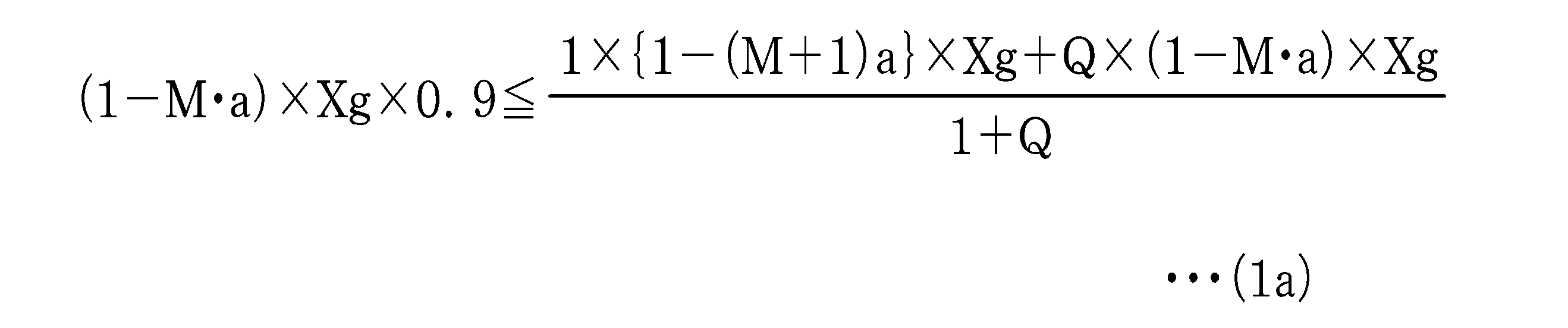
(1a)式をQについて解くと、下記(1b)式となる。Xg成分は消えてなくなる。

一方、ケース2の場合は、図17Bに示すように、1個の測定画素Aが平坦部分を構成しない電圧信号の「高」に配置され、Q個の測定画素B、C、D、E、・・・が平坦部分を構成する電圧信号の「低」に配置されているとする。この場合に、これら全測定画素A、B、C、D、E、・・・の測定信号の平均値Vaveが、第1の測定画素B、C、D、E、・・・の測定信号Vtの110%以下であれば、条件2を満たすことになる。この場合には、次の条件式が成立する。
Vave≦Vt×1.1
この式をケース1と同様に表すと、下記(2a)式となる。
Vave≦Vt×1.1
この式をケース1と同様に表すと、下記(2a)式となる。
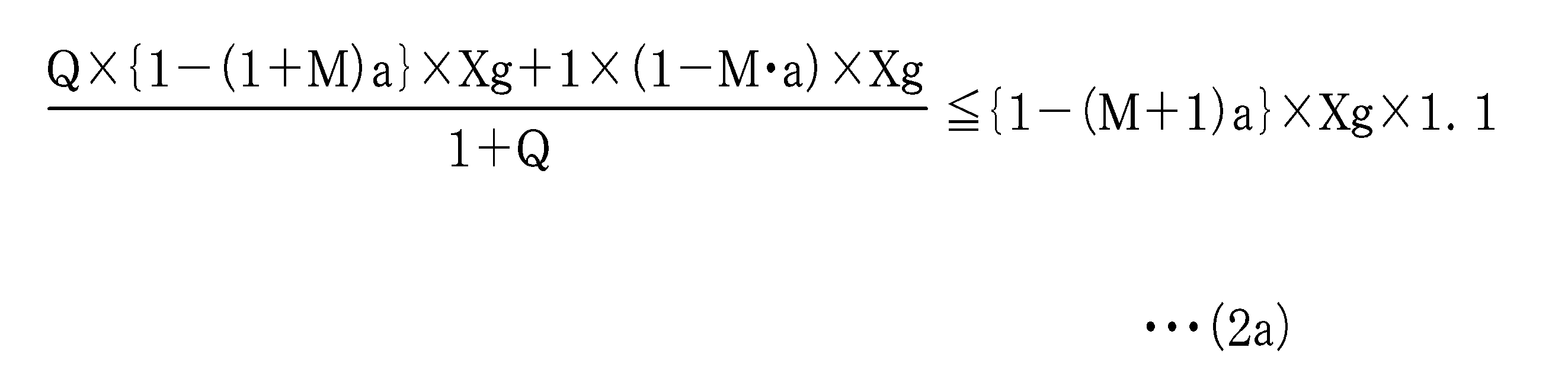
(2a)式をQについて解くと、下記(2b)式となる。(1b)式の場合と同じく、Xg成分は消える。

(1b)、(2b)いずれの条件式とも、画素40に投影されるX線吸収層36の本数の最小値M本あるいは最大値M+1本と、X線吸収層36の吸収率aが分れば、1個の第2の測定画素40b2に対する第1の測定画素40b1の個数Qを規定する条件式が求まる。図13等に示すように、本数MはfG/fNの値に応じて規則的に切り替わるのでfG/fNの値から求まる。また、発明者らの実験によると、例えば画素ピッチΔ=150μmのとき、グリッド14としてグリッドピッチG=250μm(40本/cm)、グリッド比14:1のものを用いた場合、X線吸収層36の影響を最も受ける画素と、最も受けない画素の画素値の差として吸収率a=0.2(20%)程度であることが分かっている。この吸収率aの値を定めるには、例えば、被写体Hが存在しない状態でグリッド14のみをX線撮影し、これにより得られた画像の全体あるいは関心領域に相当する範囲において、X線透過層35とX線吸収層36の配列方向と直交する方向に連なる画素40の画素値を求める。次に、画素値の最大値と最小値の差とX線吸収層36の本数を加味して、比率として吸収率aを求めればよい。上に例示した画素ピッチΔ=150μm、グリッドピッチG=250μmの場合は、X線吸収層36の本数は0本か1本となるため、画素値の最大値と最小値の差を0本の位置で測定した線量で割った値がそのまま吸収率aとなる。
したがって、fG/fNの値から求まるMと、代表値としてa=0.2とを上記条件式に代入すれば個数Qの条件が分かる。なお、グリッドによっては吸収率aが0.1以下のものもあるが、この場合は条件2は考慮しなくてもよいことが多く、吸収率aが0.1以下の場合は条件1と条件3の少なくとも一方を満たすようにして測定画素40bの出力への信頼性を向上させることが重要である。
なお、吸収率aを算出する際の画素値の最大値と最小値の差と、0本の位置で測定した線量は、ある特定の位置で測定した値であってもよいし、複数の位置で測定した値の平均値であってもよい。また、例えばX線吸収層36の本数が1本か2本の場合には、画素値の最大値と最小値の差は、1本分のX線吸収層36が吸収したX線の線量となる。吸収する線量はほぼ本数に比例するため、画素値の最大値と最小値の差の値に本数を乗算することで照射されたX線量を推測することができ、これと画素値の最大値と最小値の差に基づいて吸収率aを計算することができる。
実際には吸収率aをわざわざ計算しなくても、被写体Hが存在しない状態でグリッド14のみを撮影した画像上から分かる画素値の最大値と最小値を用いて、例えば(1a)式あるいは(2a)式の(1-M・a)の部分に最大値を、そして{1-(M+1)・a}の部分に最小値をそのまま代入してもよい。これらの(1a)式、(2a)式は、分かり易くするために数式で表現しているが、実質は最大値と最小値をそのまま使用して求めることと同である。
なお、厳密にはグリッドの製造誤差等もあるため、整然とした周期性をもって、共通の最大値及び最小値が現れるわけではないが、1周期の中の極大点を最大値と判断し、1周期の中の極小点を最小値と判断してもよい。または、最悪ケースを想定して(1a)式あるいは(2a)式を満たす場合には、必ず所望の±5%の範囲に入るようになるため、単純に最小値と最大値の測定は、上記したように関心領域の範囲か、もしくは全領域で単に数値の大小だけを見て決めてもよい。こうすることで、1周期を判断する必要もなく、算出が簡便となる。
図18に示す混合画素アレイ413は、fG/fN=1/2(G=4Δ)、周期C=4、出力パターンが「高、高、高、低、高、高、高、低、・・・」であるケース1を示す。測定画素40bは、出力パターンの周期Cの4倍の20画素の範囲に、5画素周期で4個配置されている。少なくともこの4個の測定画素40bで、AEC部54でX線量の平均値を計算する一群を構成する。この場合に、最初の配置と、画素40が相対的に行方向X2に1画素、2画素、3画素ずれた場合とで、4個の測定画素40bの出力はそれぞれ「高、高、高、低」、「高、高、低、高」、「高、低、高、高」、「低、高、高、高」となる。いずれの場合も、第1の測定画素40b1は3個で、第2の測定画素40b2は1個である。
これはケース1であるため、(1b)式を適用する。fG/fN=1/2であるから、M=0である。またa=0.2とすると、(1b)式は、次のようになる。
Q≧(0.2×10⁻¹)/1=1
このため1個の第2の測定画素40b2に対して第1の測定画素40b1を1個以上とすればよい。図18の例では個数Q=3であるので、(1b)式の条件を満たしている。
Q≧(0.2×10⁻¹)/1=1
このため1個の第2の測定画素40b2に対して第1の測定画素40b1を1個以上とすればよい。図18の例では個数Q=3であるので、(1b)式の条件を満たしている。
一方、図11のfG/fN=4/3の場合にはケース2であるため、(2b)式を適用する。(2b)式にM=0、a=0.2を代入して解くと、
Q≧[{1-(0.2×11)}/(0.2-1)}=1.5
となる。Q≧1.5の場合は、1個の第2の測定画素40b2に対して第1の測定画素40b1を2個、3個・・・とすればよい。なお、2個の第2の測定画素40b2に対して第1の測定画素40b1を3個としてもよい。以下同様に、M=1、2、・・・とa=0.2を代入して(1b)、(2b)式を解くと、個数Qの条件は吸収率a=0.2のときにfG/fNの値に応じて図19に示すように切り替わることが分かる。
Q≧[{1-(0.2×11)}/(0.2-1)}=1.5
となる。Q≧1.5の場合は、1個の第2の測定画素40b2に対して第1の測定画素40b1を2個、3個・・・とすればよい。なお、2個の第2の測定画素40b2に対して第1の測定画素40b1を3個としてもよい。以下同様に、M=1、2、・・・とa=0.2を代入して(1b)、(2b)式を解くと、個数Qの条件は吸収率a=0.2のときにfG/fNの値に応じて図19に示すように切り替わることが分かる。
使用するグリッド14が1種類の場合は、条件式から求めた個数Qが用いられる。一方、条件式から求まるQが異なった複数のグリッドを選択して使用する場合は、複数の個数Qのうち最も大きい値を共通の個数Qとする。例えば、Q≧1.5の条件のグリッドと、Q≧7/3(≒2.3)のグリッドとを併用する場合は、Q≧7/3の条件を共通使用する。
次に、fG/fN≠整数で、測定画素40bを周期的に配置した場合に、その周期Z(単位:画素)をどう決定するかを検討する。出力パターンと測定画素40bの周期配置のパターンとを合わせてみたときの繰り返し周期Wは、出力パターンの周期Cと測定画素40bの周期Zの最小公倍数である。
W=lcm(C、Z)
「lcm」は括弧内の2個の数値の最小公倍数(Least Common Multiple)を表す。図18の例で説明すると、出力パターンの周期C=4、測定画素の周期Z=5であるので、W=20となる。
W=lcm(C、Z)
「lcm」は括弧内の2個の数値の最小公倍数(Least Common Multiple)を表す。図18の例で説明すると、出力パターンの周期C=4、測定画素の周期Z=5であるので、W=20となる。
繰り返し周期Wの中で、平坦部分を構成しない電圧信号を出力する位置に1個の第2の測定画素40b2が配置される場合に、これに対して(1b)式または(2b)式に基づいて決定したQ個以上の第1の測定画素40b1を設ける必要がある。こうした配置が可能となる条件は、周期Zで配置したQ+1個の測定画素40b、すなわち(Q+1)Z個が繰り返し周期W以下に収まっていなければならないということである。
W=lcm(C、Z)≧(Q+1)Z・・・(3)
この条件式(3)を満たすように測定画素40bの周期Zを決定する。なお、反対に(Q+1)Z個が繰り返し周期Wより大きくなってしまうような場合(W<(Q+1)Z)は、(Q+1)Zの繰り返し周期Wからはみ出した部分の測定画素40bが、前後の繰り返し周期Wのいずれかの測定画素40bと同じ位置付けとなり、1個の第2の測定画素40b2に対して、第1の測定画素40b1をQ個設けることができないことになる。
W=lcm(C、Z)≧(Q+1)Z・・・(3)
この条件式(3)を満たすように測定画素40bの周期Zを決定する。なお、反対に(Q+1)Z個が繰り返し周期Wより大きくなってしまうような場合(W<(Q+1)Z)は、(Q+1)Zの繰り返し周期Wからはみ出した部分の測定画素40bが、前後の繰り返し周期Wのいずれかの測定画素40bと同じ位置付けとなり、1個の第2の測定画素40b2に対して、第1の測定画素40b1をQ個設けることができないことになる。
図18の混合画素アレイ413では、W=20、Q=3、Z=5あるので、条件式(3)を満たしている。なお、個数Qの場合と同様に、グリッド14を複数種類切り替えて使用し、配置周期Zの条件が各グリッド14で異なる場合は、各配置周期Zの最小公倍数を最終的に決定する配置周期Zとする。例えば配置周期Z=3の条件のグリッドと、Z=4の条件のグリッドを併用する場合は、最終的に決定する配置周期Zは3と4の最小公倍数である12とする。
条件式(3)を満たすように測定画素40bの周期Zを決定すると、繰り返し周期Wの中で、第2の測定画素40b2の個数が少なくとも1個に対して、第1の測定画素40b1がQ個出現することになる。このように(1b)式または(2b)式を満たすようにQを決定し、かつ条件式(3)式を満たすように測定画素40bの周期Zを決定すれば、同じ撮影条件で複数回撮影したときに、検出したX線量のばらつきが±5%の範囲に収まるという条件2を満たし、かつ測定画素40bを周期的に配置することができる。
以上は、fG/fN≠奇数のときに、測定画素40bを周期的に配置する場合であるが、条件1を満たしていれば、測定画素40bを不規則に配置してもよい。
この場合、α×C周期目のβ個目の画素40の位置に不規則に測定画素40bを配置する。ただしα=0以上の自然数、β=1~Cのうちの任意の少なくとも3つの数である。なお、β=1~Cのうちの任意の少なくとも3つの数とするのは、第1の測定画素40b1の個数の方が、第2の測定画素40b2の個数よりも多くなるためには、最低でも前者が2個、後者が1個必要であるという理由に基づいている。
図20(A)、(B)は、測定画素40bが不規則に配置された混合画素アレイ414、415を示す。混合画素アレイ414と415は、測定画素40bが不規則配置であるが、図18の混合画素アレイ413と同じ出力パターン「高、高、高、低、高、高、高、低、・・・」となる。この混合画素アレイ414と415は、数字「1」~「4」を付した4個の画素40で1セットが構成され、各セットは1周期分の出力パターンを発生する。図20(A)では、左側に存在する第1セットでは第1番目が、第2セットでは3番目が、第3セットでは4番目が、第4セットでは2番目が測定画素40bである。この場合はα=1、2、3、4であり、β=1、3、4、2である。そして、4セット内で、不規則に配置した4個の測定画素40bを一群とし、少なくともこの一群を使用してX線量を測定する。もちろん、4セットの整数倍の測定画素40bを用いて、X線量を測定してもよい。
図20(B)では、第1セットの1、3、4番目、第2セットの2番目、第3セットの2、3番目、第4セットの1、4番目が測定画素40bである。この場合は、α=1、2または3、4であり、β=1、3、4、2または2、3、1、4である。そして、2セット(例えば第1及び第2セット、又は第3及び第4セット)内の4個の測定画素40bを一群として、X線量を測定する。もちろん、2セットの整数倍となる測定画素40bを用いてもよい。
図20(A)の混合画素アレイ414は、出力パターンの4周期の範囲を、図20(B)の混合画素アレイ415は出力パターンの2周期の範囲を1画素ずつ4回ずらしたときに、全ての回で第1の測定画素40b1の個数の方が、第2の測定画素40b2の個数よりも多くなるので、第1の条件を満たしている。また、全ての回で各個数が同じになっており、第2の条件も満たしている。図20(A)では、出力パターンの4周期にわたって測定画素40bが不規則に配置されているが、図20(B)では出力パターンの2周期にわたって不規則に測定画素40bが配置されている。本発明は、いずれも採用することができる。
これまでに示したfG/fN≠整数の例では、出力パターンの1周期で平坦部分を構成しない電圧信号が1個現れる場合であるが、それ以外の例もある。例えば、図21(A)、(B)の混合画素アレイ416、417では、fG/fN=8/7(G=7Δ/4)、出力パターンの周期C=7である。また、本数パターンが「0、1、0、1、0、1、1、・・・」、出力パターンは「高、低、高、低、高、低、低、・・・」であり、平坦部分を構成しない電圧信号「高」が3個現れている。パターンとしてはfG/fN=奇数の場合に近いが、「低」が2連続で出現する平坦部分があるため、条件1の適用範囲である。
この場合、図21(A)の混合画素アレイ416では、測定画素40bを周期Z=2画素で規則的に配置する。出力パターンの2周期分に相当する14個の画素の全体を1画素ずつ7回ずらしたときに、第1の測定画素40b1が4個、第2の測定画素40b2が3個となる。第1の測定画素40b1の方が、第2の測定画素40b2よりも個数が多いから、第1の条件を満たしている。これらの個数は、14個の画素の全体を1画素ずつ7回ずらしても変わらないので、条件3も満たしている。また図21(B)の混合画素アレイ417では、測定画素40bは不規則に配置されており、第1セットでは1、3、4、7番目、第2セットでは2、5、6番目の位置に測定画素40bが配置されている(α=1、2、β=1、3、4、7または2、5、6)。この混合画素アレイ417でも、混合画素アレイ416と同じ結果となる。混合画素アレイ416、417のいずれも、出力パターンの2周期内にある7個の測定画素40bを一群とし、少なくともこの一群を用いて、X線量の測定が行われる。
なお、fG/fN≠奇数の場合のfG/fNの範囲としては、以下の条件式(4)~(7)のいずれかであることが好ましい。
fG/fN≦2/3・・・(4)
4/3≦fG/fN≦8/3・・・(5)
10/3≦fG/fN≦14/3・・・(6)
16/3≦fG/fN≦20/3・・・(7)
fG/fN≦2/3・・・(4)
4/3≦fG/fN≦8/3・・・(5)
10/3≦fG/fN≦14/3・・・(6)
16/3≦fG/fN≦20/3・・・(7)
fG/fNの範囲を条件式(4)~(7)のいずれかにすれば、特異な点となる全ての画素40に対して、必ず平坦部分に該当する画素40が少なくとも2画素分連続して出現することとなる。また、fG/fNが偶数に近付くほど平坦部分に該当する画素40が連続する個数が増える方向になり、出力パターンの傾向が分かりやすい。測定画素40bを3画素連続して配置するという単純な方法から、上述のように周期的または不規則な配置までよいので、測定画素40bの配置の自由度が高い。さらに最適なグリッド14も選定しやすく、測定画素40bの配置も決定しやすいというメリットがある。
ここまで説明の便宜上で1行分の画素について説明しているが、実際は複数の行でX線量の測定が行われる。このため、実際には、図22Aに示すように、全てが通常画素である通常画素アレイが配置された撮像領域41に対して、通常画素アレイと混合画素アレイ60aとが置き換わるように、混合画素アレイ60aを所定のパターンで配置する。これにより、撮像領域41内で、測定画素40bが二次元に配置される。採光野内に存在する1つ又は複数の混合画素アレイ60aを選択し、これらを用いてX線量を測定する。なお、混合画素アレイ60aを、撮像領域41の全域に一様に配置しなくてもよく、例えば、左右の肺野等、予め設定される採光野にあたる特定領域にのみ配置してもよい。
図22Aに示す混合画素アレイ60aは、4個の測定画素40bを5画素周期(周期Z=5)で配置した例であり、各混合画素アレイ60aは、例えばX2方向及びY2方向に所定の間隔で規則的に配列されている。周期Zは測定画素40bの配列ピッチに相当し、画素ピッチΔの5倍である(Z=5Δ)。1個の混合画素アレイ60aは、線量測定に用いられる最小単位であり、4個の測定画素40bを有する。図22Bに示すように、2つの混合画素アレイ60aで形成される8個の測定画素40bをもつブロック61aや、図22Cに示すように、3つの混合画素アレイ60aで構成される12個の測定画素40bをもつ正方形状のブロック61bで、線量測定をしてもよい。
また、混合画素アレイ60aは1例であり、図22A~図22Cのように、測定画素40bを周期的に配置してもよいし、図20に示す混合画素アレイ414、415のように、測定画素40bを不規則に配置したものでもよい。また、各混合画素アレイ60aの間隔が不規則でもよい。また、各混合画素アレイ60aの中では、測定画素40bを不規則に配置し、各混合画素アレイ60aの間隔を規則的または不規則にしてもよい。
また、これまでは、グリッド14の縞が列方向Y2に延びるように(グリッド14の各層35、36の配列方向X1と画素40の行方向X2が平行となるように)、電子カセッテ13に対してグリッド14がセットされることを前提に説明している。しかし、グリッド14に対して電子カセッテ13を90°回転させて、グリッド14の縞が行方向X2に延びるように、グリッド14がホルダ16aにセットされることもある。この場合には、図23に示すように、線量測定に使用される一群の測定画素40bの配列方向が、列方向Y2に伸びた混合画素アレイ60bを形成した撮像領域41を用いる。この混合画素アレイ60bでは、画素ピッチΔ、測定画素40bの周期Zは、それぞれ列方向Y2で測る。
また、撮像領域41内において、混合画素アレイ60aと60bとを混在させてもよい。例えば、正方形を形成するように、2個の混合画素アレイ60aの間に、2個の混合画素アレイ60bを配置する。こうすれば、グリッド14の取り付け姿勢によって混合画素アレイ60a、60bを選択すれば、どちらの取り付け姿勢でも、正確に自動露出制御を行うことができる。また、例えば、各混合画素アレイ60b間の行方向X2の間隔を調節することにより、各混合画素アレイ60b間の測定画素40bの行方向X2の周期Zと、各混合画素アレイ60b内の列方向Y2の測定画素40bの周期Zとを一致させれば、グリッド14の取り付け姿勢に関わらず、正確に自動露出制御を行うことができる。
各実施形態では、複数の測定画素40bが1行又は1列上に配置されているが、図24に示す混合画素エリア60cのように、複数の測定画素40bを二次元エリア内で行方向X2や列方向Y2にずらして配置してもよい。
図24に示す混合画素エリア60c内において、複数の測定画素40bは、それぞれ配置される行は異なるが、行方向X2に関しては、4列分の間隔を空けて5画素周期で配置されている。行方向X2に関して、混合画素エリア60c内の測定画素40bの画素ピッチΔX、周期ZXは、図22に示す混合画素アレイ60a内の測定画素40bの画素ピッチΔ、周期Zと同じである。そのため、混合画素エリア60c内の一群の測定画素40bの線量測定信号の平均値は、混合画素エリア60a内の一群の測定画素40bの線量測定信号の平均値とほぼ同じになる。また、混合画素エリア60c内の複数の測定画素40bは、列方向Y2に関しても、配置される列は異なるが5画素周期で配置されている。列方向Y2に関して、混合画素エリア60c内の測定画素40bの画素ピッチΔY、周期ZYは、図23に示す混合画素アレイ60b内の測定画素40bの画素ピッチΔ、周期Zと同じである。
また、混合画素エリア60cは、混合画素アレイ60a、60bの両方を設けたものと同じであるから、グリッド14の取り付け姿勢に関わらず、正確に自動露出制御を行うことができる。さらに、混合画素アレイ60a、60bを混在させる場合には、グリッド14の取り付け姿勢によって各混合画素アレイ60a、60bを選択することが必要になるが、混合画素エリア60cの場合は、グリッド14の取り付け姿勢にかかわらずそのまま使用することができる。また、混合画素エリア60cの場合は、混合画素アレイ60a、60bを混在させる場合に比べて、測定画素40bの個数を半分に減らすことができる。
また、本例の測定画素40bのように、TFTと信号線43が短絡されている場合には、測定画素40bの電荷が信号線43に常時流れている。そのため、各測定画素40bが配置される行が異なっても、測定画素40bの電荷が信号処理回路45内の積分アンプ46に流入するタイミングはほぼ同じである。したがって、混合画素エリア60c内の各測定画素40bの線量測定信号を同じタイミングで読み出すことができるというメリットもある。
なお、本例の混合画素エリア60cでは、各測定画素40bの行方向X2および列方向Y2に関するずらし量を同じ(5画素分)にしているが、行方向X2と列方向Y2でずらし量を任意に変えてもよい。
以上のように、本発明では、fG/fN≠奇数、すなわちfG/fN=偶数又は分数となるように、画素ピッチΔとグリッドピッチGとを定め、少なくとも出力パターンの周期Cの範囲を1画素ずつC回ずらしたときに、全ての回で第1の測定画素40b1の個数の方が、第2の測定画素40b2の個数よりも多くしているから、X線測定量の平均値算出に用いられる一群の測定画素40bに対する第2の測定画素40b2による影響が薄められる。これにより、電子カセッテ13とグリッド14の位置関係がずれても、一群の測定画素40bの全体から求められる平均値又は加算値は、ほぼ一定となる。
また、少なくとも出力パターンの周期Cの範囲を1画素ずつC回ずらしたときに、全ての回で、第1の測定画素40b1の個数と、第2の測定画素40b2の個数のいずれも変化をしないように配置した場合は、電子カセッテ13とグリッド14の位置関係によらず、一群の測定画素40bの線量測定信号の平均値又は加算値は、一定となる。fG/fN=偶数の条件を満たすように、画素ピッチΔとグリッドピッチGとを定めた場合も同様である。
さらに、同じ撮影条件で複数回撮影したときの照射X線量(露出量)のばらつきが±5%の範囲に収まるように、1個の第2の測定画素40b2に対する第1の測定画素40b1の個数Qを規定した場合は、照射X線量のばらつきは多少生じるものの測定画素40bの配置の自由度が増える。測定画素40bは構造や欠陥補正の仕方によってはX線画像で欠損として視認されてしまう問題があるが、実際上では測定画素40bが集中配置されて、数画素程度のかたまりとなったときに問題となる。そこで、測定画素40bが欠損として視認されてしまう問題が生じないように、測定画素40bをある程度分散して配置させることが可能となるような自由度をもつことが重要である。
測定画素40bを周期的に配置する場合は、画像検出部30の製造が容易になる。また、グリッド14を複数種類切り替えて使用する場合に、全種類の条件を満たすように個数Qや配置周期Zを決定すれば、汎用性を高めることができる。
なお、測定画素40bを周期的に配置する場合は、そのナイキスト周波数fA=1/(2ΔZ)=fN/Zとグリッド周波数fGとの比fG/fA=偶数、またはfG/fA≠整数とすれば、測定画素40bの線量測定信号の出力レベルが一定になるか、又は線量測定信号の出力パターンに平坦部分が出現する。この場合に、少なくとも出力パターンの周期Cの範囲を1画素ずつC回ずらしたときに、必ず全ての回で第1の測定画素40b1の個数の方が、第2の測定画素40b2の個数よりも多くなる。このために、第2の測定画素40b2の出力による一群の測定画素40bの出力への影響が薄められ、累積線量のばらつきを軽減することができる。
同じ撮影条件で複数回撮影したときの放射線の累積線量がばらつく要因としては、これまで説明してきた一群の測定画素40bの平均値のばらつきの他に、線源制御装置11の照射信号I/F25から照射開始信号を送信してから、これを電子カセッテ13の照射信号I/F55で受信してAEC部54による線量測定を開始するまでの時間(照射開始の同期時間)のばらつきがある。また、照射信号I/F55から照射停止信号を送信してから、これを照射信号I/F25で受信して実際に線源制御装置11の制御部21によりX線源10のX線の照射を停止させるまでの時間(照射停止の同期時間)のばらつきもある。したがって、これら照射開始、停止の同期時間のばらつきも含めて同じ撮影条件で複数回撮影したときの放射線の照射量のばらつきを±5%の範囲に収めるためには、一群の測定画素40bの平均値のばらつきの許容範囲を少なくとも±5%よりも厳しくする必要がある。このため(1a)式の左辺の「0.9」や(2a)式の右辺の「1.1」は、この値に制約されるべきでない。一群の測定画素40bの全ての回の平均値のばらつきの許容範囲を±k%とした場合、(1b)式および(2b)式は下記(1c)式および(2c)に書き換えられる。


発明者らの実験によれば、有線通信での照射開始、停止の同期時間のばらつきは、その合計で0.5msec程度である。例えば、照射時間20msecで胸部撮影した場合は照射開始、照射停止の同期時間を要因とする累積線量のばらつきは、0.5/20=0.025である。これは、2.5%であるため、一群の測定画素40bの平均値のばらつきの許容範囲を±2.5%以下(k≦2.5)とするのがよい。
上記実施形態では説明の便宜上、図16の(A)に示すように3個連続して測定画素40bを配置したり、図16の(B)のように4画素毎に測定画素40bを配置したり、図18のように5画素周期で測定画素40bを配置したりしている。一般的に、測定画素40bは欠陥画素として扱われるので個数は少ないほどよく、全画素40に対して測定画素40bの占める割合は約0.01%(100ppm;ppm(Parts Per Million)=0.0001%)程度であることが好ましい。また、10画素程度の欠陥画素のかたまりがあると欠陥補正をしても目立つので、複数の測定画素40bをまとめて配置する場合には、10画素より少なくすることが好ましい。
上記実施形態では、周期性が重要となってくるため、グリッドと画素の相対位置がある一定の位置(グリッドと画素の左端が揃った位置)で、かつX線吸収層の幅がある一定の幅の例について説明している。グリッドと画素の左端が揃っていない場合や、グリッドと画素の相対位置が一定でない場合について補足説明する。例えば図10では、fG/fN=2/3で出力パターンの周期C=3、本数パターンは「0、0、1」の1周期が繰り返す場合を示している。この状態から例えば0.2画素分だけグリッドの左端が左にずれたと仮定すると、本数パターンは「0、0.2、0.8、0、0.2、0.8、・・・」となり、「0、0.2、0.8」の1周期が繰返されることとなる。本数パターンの周期は、ずれる前と同じ3画素であり、出力パターンの周期Cも3画素である。
ここで、図16の(A)の場合と同様に、左端の隣接する3個の画素40が測定画素40bで、続く3個の画素40が通常画素40aであり、これが繰り返す配置を考える。画素40が相対的に行方向X2に1画素ずつずれていった場合に、1画素ずれた場合(2回目)の測定画素40bの本数パターンは「0.2、0.8、0」となり、2画素ずれた場合(3回目)は「0.8、0、0.2」となる。いずれの場合も1個の測定画素40bに掛かるX線吸収層36の本数の平均値は1/3本と等しくなる。また、図16の(A)の最初の位置(1回目)の本数パターン「0、0、1」と比較しても、1個の測定画素40bに掛かるX線吸収層36の本数の平均値は両者共に同じ1/3本である。これは条件3に該当する。すなわち、最初の位置が0.2画素分等の1画素未満のずれであっても、測定結果は変わらない。更に、最初の位置から1画素未満だけ画素をずらしても、測定結果は同じである。
さらに異なる例で説明する。fG/fN=1/2(G=4Δ)の場合、グリッド14と画素40の左端が揃った状態では、本数パターンは「0、0、0、1」を1周期とする繰り返しとなる。このとき、図16の(A)の場合と同様に左端の隣接する3個の画素40を測定画素40bとすると、最初の位置(1回目)の測定画素40bの本数パターンは「0、0、0」である。1画素ずれた場合(2回目)は「0、0、1」であり、2画素ずれた場合(3回目)は「0、1、0」である。3画素ずれた場合(4回目)は「1、0、0」となる。隣接する3個の測定画素40bでX線量を測定する場合は、測定画素40bの出力の変動幅は、3画素とも本数パターンが「0」の場合と、2画素が0本で、残りの1画素が1本の場合との差となる。これにより、1個の測定画素40bに掛かるX線吸収層36の本数の平均値は、0本又は1/3本となる。これは条件1に該当する。
上記の状態から、例えば0.2画素分だけグリッドの左端が左にずれたとすると、本数パターンは「0、0、0.2、0.8、0、0、0.2、0.8、・・・」となる。左端の隣接する3個の測定画素40bの本数パターンは、最初の位置(1回目)では「0、0、0.2」となり、1画素ずれた場合(2回目)は「0、0.2、0.8」となる。また、2画素ずれた場合(3回目)は「0.2、0.8、0」となり、3画素ずれた場合(4回目)は「0.8、0、0」となる。これから分かるように、いずれにしても3個の測定画素40bに掛かるX線吸収層36の本数の合計が1本を越えることはないことから、1個の測定画素40bに掛かるX線吸収層36の本数の平均値も0本から1/3本の間となる。すなわち、最初の位置が0.2画素分等の半端な画素分ずれていたとしても、又は最初の位置からずらす量が半端な画素分であっても、1個の測定画素40bに掛かるX線吸収層36の本数の平均値のばらつきの最大値は1本分であり、このばらつきの最大値を考えて測定画素40bの位置を決めればよい。
結局、任意の2つの画素の出力がX線吸収層36の1本分ばらつくことを考えておけば、1本分以下でばらつくその他のケースは、そもそもこの1本分のばらつきが複数の測定画素40bに分散して平均化されている状態であると云える。したがって、一群の測定画素40bの出力の変動幅も1本以上になることはない。このばらつきが最大となる場合を考えて、第1の測定画素40b1の個数の方が、第2の測定画素40b2の個数よりも多くなるように、測定画素40bを配置または選択をすれば、最初の位置が半端な画素分ずれていた場合でも、最初の位置からずらす量が半端な画素分である場合でも、特異な点(出力が極大値又は極小値となる点)の影響を抑えることができる。
なお、グリッドは製造誤差があるが、発明者らが確認したところによるとグリッドの製造誤差は1%よりも大分小さいことが分かっている。例えば60本/cmのグリッドの場合、製造誤差が1%であれば59.4本/cm~60.6本/cmの範囲となるが、誤差が1本以下で微差であり本発明の累積線量のばらつきを軽減する効果に影響を与えるものではない。
ただし、規格上許されるグリッドの製造誤差は±10%の範囲であるため、最悪のケースを考えると、公称60本/cmのグリッドの場合は、54本/cm~66本/cmの範囲となる。製造元によっては、上記規格を満足していれば合格品として販売するところもあり、製造誤差が1%以上のグリッドも一定数出回っている。しかし、こうしたグリッドを使用する場合も、全体最適を考えると当然に中心値である60本/cmに合わせて、測定画素40bを配置または選択するべきである。これは製造誤差が1%未満の場合にも同じく言えることである。このようにグリッドの製造誤差によるX線吸収層の本数のばらつきの範囲の中心値に合わせれば、累積線量のばらつきの軽減に大きな効果がある。また、使用するグリッド毎に、被写体が存在しない状態でグリッドのみをX線撮影し、得られた画像から実際のX線吸収層の本数を求め、これに基づいて測定画素40bの配置または選択を決めてもよい。
または、公称60本/cmであり、54本/cm~66本/cmの範囲の製造誤差があるグリッドを使用し、かつ図14に示すように画素ピッチΔ=125μmである場合は、fG/fNは、4/3~2の範囲となる。図13から分かるように、fG/fNの値が4/3から2に近付くに連れて、出力パターンにX線吸収層の本数が0本となる特異な点に対して、X線吸収層の本数が1本となる平坦部分が徐々に増えていくことになる。これを踏まえて、仮に製造誤差の範囲の最小値の54本/cmに合わせて測定画素40bを配置または選択しておけば、60本/cm、66本/cmと本数が増えるにつれて、平坦部分が徐々に増える。結果として、平坦部分に配置される測定画素の個数も増えていくため、特異な点の影響が薄まる方向に進む。
上記の考え方を一般化すると、グリッドの製造誤差の範囲の最小値と画素Δの関係が、4/3≦fG/fN<2、10/3≦fG/fN<4、16/3≦fG/fN<6のいずれかの範囲に収まる場合は、最小値を基準に最適化して、測定画素の位置を決定する。逆にグリッドの製造誤差の最大値と画素Δの関係が、fG/fN<1、2<fG/fN≦8/3、4<fG/fN≦14/3、6<fG/fN≦20/3のいずれかの範囲に収まる場合は、最大値を基準に最適化して、測定画素の位置を決定する。こうすることでグリッドに製造誤差があったとしてもこれを無視することができ、本発明の効果を発揮することができる。なお、任意の画素ピッチΔに対して、グリッドの製造誤差の範囲の最小値と最大値を用いて計算したfG/fNの2つの値の間に、偶数が存在している場合は、最小値と最大値のいずれを基準にするか判断することができない。しかし、fG/fNの2つの値の間に、偶数が存在している場合は、画素ピッチΔとグリッドピッチGの関係がfG/fN=偶数に近いということであり、一群の測定画素40bの出力の変動幅も小さくなるので、中心値に合わせて測定画素40bの位置を決めれば充分である。
また上記実施形態は、X線透過層とX線吸収層の配列方向X1に平行な方向にグリッドと測定画素が相対的にずれる例である。これは電子カセッテを撮影台のホルダにセットするときに、電子カセッテは長方形であるため上下の2方向から挟み込んで固定する形態が多く、こうした形態では電子カセッテはY1方向にずれることないが、X1方向にはある程度のガタをもたせているため、X1方向にずれやすいことが理由の1つである。逆にX1方向が固定でY1方向にずれるような形態の場合は、電子カセッテとグリッドとの位置ずれによる測定誤差は起きない。
別のケースとして、X1方向とY1方向の双方に多少のガタつきがある形態を考える。この場合、グリッドが画素に対して多少傾斜することがある。画素に対して90°の傾斜まではグリッドピッチがあたかも大きくなったかのように見えることになる。例えば60本/cmのグリッドの場合に、グリッドピッチGは約167μmである。このグリッドが10°傾いたとすると、そのときのグリッドピッチGは167/cos10°=約170μm(約59本/cm)となる。傾き角をθとすると、グリッドピッチGが傾斜していない場合の値より、1/cosθ倍だけ大きくなる。θ=10°では、1/cosθ=約1.02である。X1方向とY1方向の双方にガタつきがあったとしても、グリッドが画素に対して10°も傾いて使用されることは実用上ではあり得ない。仮に10°傾いたとしても、最大で+2%程度の誤差であり、これは一般的に上述したグリッドの製造誤差±10%よりも小さく、影響はほぼない。したがって、グリッドが画素に対して多少傾斜していても、グリッドの製造誤差のところで述べたように中心値に合わせて測定画素40bの位置を決定すれば問題ない。また、傾き角θの範囲が分かっている場合は、グリッドピッチGの最大値を計算して、上述したグリッドの製造誤差の場合と同様に、fG/fNの範囲に応じて基準を最小値または最大値において最適化して、測定画素の位置を決定すればよい。
また、グリッド14は、電子カセッテ13の筐体31や撮影台16のホルダ16aに取り付けられるため、グリッド14と撮像領域41との間には少なくとも筐体31の厚み分の間隔が空く。このため撮像領域41へのグリッド14の投影像は、グリッド14と撮像領域41とが接触していると場合よりも実際は拡大される。上記実施形態において、出力パターンの周期Cを算出する式では、グリッド14と撮像領域41の間隔を考慮していない。しかし、グリッド14と撮像領域41との間の間隔は、X線源10のX線管の焦点10aと撮像領域41間の距離(SID;Source Image Distance)と比べて十分小さいため、グリッド14と撮像領域41とが接触していると場合と比べて撮像領域41へのグリッド14の投影像の拡大率は微々たるものである。そのため、出力パターンの周期Cを算出する式において、グリッド14と撮像領域41の間隔を考慮しなくても問題はない。もちろん、より正確を期すために、グリッド14と撮像領域41との間の距離を考慮した計算式を立てて、出力パターンの周期Cを算出してもよい。なお、被写体Hが存在しない状態でグリッド14をX線撮影して得られたX線画像の縞模様から周期Cを実験的に求める場合は、X線画像に映る縞模様はグリッド14と撮像領域41との間隔を反映したものであるため、グリッド14と撮像領域41の間隔に注意を払う必要はない。
X線撮影システムには、線源制御装置11と電子カセッテ13との間に通信機能がないものがある。この場合には、線源制御装置11と電子カセッテ13へ照射開始信号が送られない。通信機能がないX線撮影システムでは、図25に示すように、画像検出部65に、照射開始判定部(以下、判定部という)66が設けられる。この判定部66には、照射開始閾値が保存されており、測定値と比較して、X線の照射開始の時点を判定する。また、検査オーダの内容に基づいて、コンソール15からX線の照射時間が入力される。この照射時間は、電子カセッテ13に送られる。なお、線源制御装置11と電子カセッテ13との間に通信機能がないため、AEC部54は設けられていない。
X線撮影の待機中に、比較的短いサイクルで積分アンプ46をリセットして、一群の測定画素40bによるX線量の測定を繰り返して行う。各回で測定した各測定画素40bの測定値は、メモリ51に送られる。この実施形態では、X線の照射を検出するものであるから、メモリ51では前回の測定値が今回の測定値で更新される。メモリ51が新しい測定値で更新されると、判定部66は、照射野内に存在する一群の測定画素40b、又は照射野内の全部の測定画素40bの測定値をメモリ51から読み出し、その平均値を算出する。なお、測定画素40bは、撮像領域内であって、被写体を透過せずにX線が直接照射される素抜け領域に存在するものを選択し、これらを用いて照射開始を判断するのがよい。また、測定画素40bの代わりに、素抜け領域に専用の線量測定センサ群を配置してもよい。
判定部66は、平均値が照射開始閾値を超えたときに、X線の照射が開始されたものと判定する。判定部66がX線照射開始と判定した場合に、制御部52は画像検出部65の動作をリセット動作から蓄積動作に移行させ、前述したように通常画素40aでX線画像を検出する。制御部52は、X線の照射開始からの経過時間を測定し、コンソール15で設定されたX線照射時間が経過すると蓄積動作を終了する。X線撮影の終了後は、前述したように電子カセッテ13からX線画像が読み出される。
グリッドあり撮影では、電子カセッテ13の前にグリッド14が配置されるが、前述した条件に基づいて測定画素40bを配置することで、電子カセッテ13とグリッド14との間で位置ずれが生じても、その影響を受けることがない。これにより、電子カセッテ13は、X線の照射開始を正確に検出して、画像検出部65によるX線画像の検出を行うことができる。
上記各実施形態では、図5に示すように通常画素40aと測定画素40bが同じ信号線43に接続されている。測定画素40bは、欠陥画素になるため、通常画素40aに比べて個数が非常に少ない。通常画素40aはTFTがオフ状態であっても微量のリーク電流が流れ出しており、個数が測定画素40bに比較し非常に多いので、測定画素40bからの電荷に通常画素41aのリーク電流に基づく電荷が加算されて、線量測定信号にノイズとして与える影響が大きいという問題がある。そこで、測定画素40bがある列(例えば図5の電圧信号V2を出力する列)に隣接して測定画素40bがない列(図5の電圧信号V1またはV3を出力する列)を設け、AEC部54で線量測定信号をサンプリングする際に、測定画素40bが存在する列の出力から、測定画素40bがない列の出力の差分をとって、リーク電流に基づく電荷の影響を取り除いて、測定画素40bからの電荷に基づく出力のみを取り出すことが好ましい。このため、測定画素40bは、図16の(A)に示すように連続して配置するよりは、(B)に示すように2つの測定画素40bの間に、少なくとも1つ通常画素40aを配置することが好ましい。
上記実施形態では、測定画素40bは、ゲートドライバ44で駆動される読み出し用のTFTのソース電極とドレイン電極が短絡されている。この読み出し用TFTを短絡する代わりに、測定用のTFTを全画素40に設けてもよい。蓄積動作中のために読み出し用のTFTがオフ状態とされている間に、測定用のTFTを選択的にオン状態として該画素40で発生した電荷を積分アンプ46のキャパシタ46bに流入させてもよい。この測定用のTFTが選択的にオンされる画素40が測定画素40bとして用いられる。こうすれば、複数種類のグリッド14を選択使用する場合に、各グリッド14の種類に対応して、通常画素40aを測定画素40bに変更することができる。この場合には、各グリッド14の位置データがメモリに記憶されている。制御部52は、使用するグリッドに対応した位置データを読み出す。そして、専用のゲートドライバを駆動し、位置データで指定された測定画素40bの測定用TFTを所定のサイクルでオンにして、所定時間毎に蓄積した電荷を読み出し、所定時間当たりのX線量を測定する。
また、各画素にバイアス電圧を供給するバイアス線に、画素で発生する電荷に基づく電流が流れることを利用して、ある特定の画素に繋がるバイアス線の電流をサンプリングしてX線量を検出してもよい。この場合はバイアス線の電流をサンプリングする画素が測定画素となる。同様に画素から流れ出るリーク電流をサンプリングして線量を検出してもよく、この場合もリーク電流をサンプリングする画素が測定画素となる。
上記実施形態では、画素40を所定のピッチΔで二次元的に撮像領域内に配置し、そのうちの一部を測定画素40bとし、残りを通常画素40aとしたものであり、通常画素40aと測定画素40bとは同サイズである。なお、測定画素40bは、通常画素40aよりも、サイズが大きくても、あるいは小さくてもよい。また、X2又はY2方向に伸びた細長な線量測定センサを用い、通常画素40aの列又は行の間に、前述した条件を満たすように配置してもよい。ただし、欠陥補正をしても目立たなくするために、線量測定センサの長さは、画素40の10個を1列に並べた場合よりも短くする。
上記実施形態では、TFT型の画像検出部を例示しているが、CMOS(Complementary Metal Oxide Semiconductor)型の画像検出部を用いてもよい。また、可搬型のX線画像検出装置である電子カセッテに限らず、撮影台内に取り付けた内蔵タイプのX線画像検出装置に適用してもよい。さらに、本発明は、X線に限らず、γ線等の他の放射線を撮影対象とした場合にも適用することができる。
なお、本発明は上記実施形態に制限されず、実施形態に記載される構成の範囲において、それぞれを組み合わせ可能である。
Claims (20)
- 撮像領域が形成された画像検出部を有し、この画像検出部の前に配置可能なグリッドとともに使用される放射線画像検出装置であって、
前記グリッドは、放射線が被写体を透過する際に発生する散乱線を除去するために、第1方向に延びる短冊状の放射線透過層と放射線吸収層とが、グリッドピッチGで前記第1方向と直交する第2方向に交互に複数形成されており、
前記撮像領域には、前記第2方向に画素ピッチΔで配置された複数の画素と、複数の線量測定センサとが配置されており、前記複数の画素は前記被写体の放射線画像を検出するために前記放射線の到達線量に応じた電荷を読み出し可能に蓄積し、前記複数の線量測定センサは前記放射線の到達線量を測定するものであり、
前記放射線画像検出装置は以下を含む:
前記画像検出部で前記グリッドの放射線画像を撮影するときに、出力信号が極大値または極小値となる特異な位置にない前記線量測定センサを第1の線量測定センサとし、前記特異な位置にある前記線量測定センサを第2の線量測定センサとしたときに、以下の条件1を満たすように、前記複数の線量測定センサの位置が決められる。
条件1:
fG/fN≠奇数であって、前記グリッドと前記画素を相対的に前記第2方向に1画素ずつC回ずらしたときに、周期Cの範囲内では、全ての回で前記第1の線量測定センサの個数が前記第2の線量測定センサの個数よりも多い。
ここで、各記号は以下の通り:
fG=1/G:グリッド周波数、
fN=1/(2Δ):前記画素のナイキスト周波数、
周期C:前記グリッドの放射線画像上で前記第2方向に現れる繰り返しパターンの周期であり、単位は前記画素の個数。 - 前記複数の線量測定センサのうち、前記第2方向に配置されており、前記周期Cに相当する個数のものを一群の線量測定センサとし、少なくとも一群の線量測定センサの測定値に基づいて放射線の照射状態を判定する判定部と、
前記判定部の判定結果に応じた制御をする制御部と、
を更に備えている請求項1に記載の放射線画像検出装置。 - 前記画素は、放射線画像を検出するため通常画素と、この通常画素と同サイズであって、前記線量測定センサとして用いられる測定画素とを有し、前記通常画素と前記測定画素とが混在した状態で、前記第1及び第2方向に二次元に配置されている請求項2に記載の放射線画像検出装置。
- 前記通常画素と前記測定画素とは共通の信号処理回路に接続されており、前記放射線の照射中には、前記通常画素の前記電荷は蓄積され、前記測定画素の電荷は前記信号処理回路に取り出される請求項3に記載の放射線画像検出装置。
- 更に、前記一群の測定画素は、以下の条件2を満たすように位置が決められる請求項3に記載の放射線画像検出装置。
条件2:
前記グリッドと前記画素を相対的に1画素ずつずらしたときに、前記全ての回で以下の条件式1、または条件式2を満たす。
条件式1:2j<fG/fN<2j+1のとき、


Q:第2の測定画素の1個に対する第1の測定画素の個数、
a:前記放射線吸収層の1本分の放射線吸収率、
M:前記測定画素に投影される前記放射線吸収層の本数の最小値、
k:前記全ての回において、前記一群の測定画素の前記測定値のばらつきの許容範囲(±k%)、
j:整数。 - k≦5である請求項5に記載の放射線画像検出装置。
- k≦2.5である請求項5に記載の放射線画像検出装置。
- 前記測定画素の配置周期をZ(画素数)とし、前記Cと前記Zの最小公倍数をlcm(C、Z)とするときに、以下の条件式3を満たすように、前記測定画素の配置周期Zが決定される請求項5に記載の放射線画像検出装置。
条件式3:lcm(C、Z)≧(Q+1)Z - 前記Qの最小値が異なる複数のグリッドを選択的に使用する場合には、複数のQの最小値のうちで最も大きい値を共通に用いる請求項8に記載の放射線画像検出装置。
- 配置周期Zの条件が異なる複数のグリッドを選択的に使用する場合には、複数の配置周期Zの最小公倍数を各グリッドに共通な配置周期Zとして使用する請求項8に記載の放射線画像検出装置。
- 前記一群の測定画素の位置が不規則に決められる請求項5に記載の放射線画像検出装置。
- 前記条件1のとき、前記画素ピッチΔと前記グリッドピッチGの値が、以下の条件式1~4のいずれかを満たすように定められる請求項3に記載の放射線画像検出装置。
条件式1:fG/fN≦2/3
条件式2:4/3≦fG/fN≦8/3
条件式3:10/3≦fG/fN≦14/3
条件式4:16/3≦fG/fN≦20/3 - 前記条件1のとき、前記画素ピッチΔと前記グリッドピッチGの値が、以下の条件式4~7のいずれかを満たすように定められる請求項8に記載の放射線画像検出装置。
条件式4:fG/fN≦2/3
条件式5:4/3≦fG/fN≦8/3
条件式6:10/3≦fG/fN≦14/3
条件式7:16/3≦fG/fN≦20/3 - 前記測定画素の配置周期Zと、前記測定画素のナイキスト周波数fNとの比であるfN/ZがfAであるときに、fG/fA=偶数、またはfG/fA≠整数となるように、前記画素ピッチΔと、前記グリッドピッチGと、前記配置周期Zの値とが定められる請求項3に記載の放射線画像検出装置。
- 前記条件1のとき、前記一群の測定画素は、更に、以下の条件3を満たすように位置が決められる請求項3に記載の放射線画像検出装置。
条件3:
前記第1の測定画素の個数が前記全ての回で同じで、かつ前記第2の測定画素の個数も前記全ての回で同じになる。 - 前記判定部は、前記各測定画素で測定した放射線量を積算した合計放射線量又はその平均値が目標線量に達したか否かを判定し、合計放射線量又は平均値が目標線量に達したと判定したときに、放射線の照射を停止させる自動露出制御が行われる請求項3に記載の放射線画像検出装置。
- 前記第2方向に対して規定した前記一群の測定画素の位置の決定が、前記第1方向にも適用される請求項3に記載の放射線画像検出装置。
- 前記画像検出部が可搬型の筐体に収納された電子カセッテである請求項3に記載の放射線画像検出装置。
- 被写体に向けて放射線を照射する放射線源と、
前記放射線源の駆動を制御する線源制御装置と、
請求項1に記載の放射線画像検出装置と、
を備えている放射線撮影システム。 - 被写体に向けて放射線を照射する放射線源と、前記放射線源の駆動を制御する線源制御装置と、請求項1に記載の放射線画像検出装置とを備える放射線撮影システムの作動方法は、以下のステップを備える:
前記複数の線量群定センサのうちの少なくとも一群の線量測定センサで放射線量を測定すること;
前記一群の線量測定センサで測定した各放射線量を積算した合計放射線量又はその平均値が目標線量に達したか否かを判定すること;及び
前記合計放射線量又その平均値が目標線量に達したときに、放射線源の駆動を停止して放射線の照射を停止させること。
Priority Applications (2)
| Application Number | Priority Date | Filing Date | Title |
|---|---|---|---|
| CN201380045229.0A CN104602607B (zh) | 2012-07-27 | 2013-06-06 | 放射线图像检测装置、放射线摄影系统及其动作方法 |
| US14/604,939 US9793305B2 (en) | 2012-07-27 | 2015-01-26 | Radiation image detecting device, radiation imaging system and operation method thereof |
Applications Claiming Priority (4)
| Application Number | Priority Date | Filing Date | Title |
|---|---|---|---|
| JP2012-166875 | 2012-07-27 | ||
| JP2012166875 | 2012-07-27 | ||
| JP2013109300A JP5808365B2 (ja) | 2012-07-27 | 2013-05-23 | 放射線画像検出装置、並びに放射線撮影システムおよびその作動方法 |
| JP2013-109300 | 2013-05-23 |
Related Child Applications (1)
| Application Number | Title | Priority Date | Filing Date |
|---|---|---|---|
| US14/604,939 Continuation US9793305B2 (en) | 2012-07-27 | 2015-01-26 | Radiation image detecting device, radiation imaging system and operation method thereof |
Publications (1)
| Publication Number | Publication Date |
|---|---|
| WO2014017179A1 true WO2014017179A1 (ja) | 2014-01-30 |
Family
ID=49996996
Family Applications (1)
| Application Number | Title | Priority Date | Filing Date |
|---|---|---|---|
| PCT/JP2013/065668 Ceased WO2014017179A1 (ja) | 2012-07-27 | 2013-06-06 | 放射線画像検出装置、並びに放射線撮影システム及びその作動方法 |
Country Status (4)
| Country | Link |
|---|---|
| US (1) | US9793305B2 (ja) |
| JP (1) | JP5808365B2 (ja) |
| CN (1) | CN104602607B (ja) |
| WO (1) | WO2014017179A1 (ja) |
Cited By (1)
| Publication number | Priority date | Publication date | Assignee | Title |
|---|---|---|---|---|
| CN109946916A (zh) * | 2019-04-25 | 2019-06-28 | 合肥工业大学 | 一种基于多层透明散射屏的投影光场显示装置和显示方法 |
Families Citing this family (22)
| Publication number | Priority date | Publication date | Assignee | Title |
|---|---|---|---|---|
| JP6021403B2 (ja) * | 2012-04-19 | 2016-11-09 | キヤノン株式会社 | 放射線撮像装置 |
| JP6257916B2 (ja) * | 2013-04-26 | 2018-01-10 | 東芝メディカルシステムズ株式会社 | 光検出装置、放射線検出装置、放射線分析装置及び光検出方法 |
| US9554759B2 (en) * | 2013-09-18 | 2017-01-31 | Carestream Health, Inc. | Digital radiography detector image readout process |
| US9197885B2 (en) | 2014-03-20 | 2015-11-24 | Gopro, Inc. | Target-less auto-alignment of image sensors in a multi-camera system |
| US8988509B1 (en) | 2014-03-20 | 2015-03-24 | Gopro, Inc. | Auto-alignment of image sensors in a multi-camera system |
| US10459094B2 (en) * | 2014-04-30 | 2019-10-29 | Analogic Corporation | Detector array for imaging modality |
| JP6161080B2 (ja) * | 2014-09-24 | 2017-07-12 | 富士フイルム株式会社 | 画像解析装置および方法並びにプログラム |
| US10058301B2 (en) * | 2014-09-24 | 2018-08-28 | Fujifilm Corporation | Image analysis device, image analysis method, and program |
| JP6700737B2 (ja) * | 2015-11-20 | 2020-05-27 | キヤノン株式会社 | 放射線撮像システム、信号処理装置、及び、放射線画像の信号処理方法 |
| WO2017163149A1 (en) * | 2016-03-23 | 2017-09-28 | Koninklijke Philips N.V. | Nano-material imaging detector with an integral pixel border |
| JP6811673B2 (ja) * | 2017-04-25 | 2021-01-13 | 富士フイルム株式会社 | 放射線照射検出システムおよび放射線発生装置 |
| JP7087435B2 (ja) * | 2018-02-19 | 2022-06-21 | コニカミノルタ株式会社 | 放射線画像撮影装置及び放射線画像撮影システム |
| WO2019202695A1 (ja) * | 2018-04-19 | 2019-10-24 | 株式会社島津製作所 | X線撮影システム |
| CN110432917B (zh) * | 2018-05-04 | 2023-07-25 | 上海西门子医疗器械有限公司 | 曝光剂量修正方法和设备、存储介质及x-射线医疗系统 |
| WO2020056614A1 (en) * | 2018-09-19 | 2020-03-26 | Shenzhen Xpectvision Technology Co., Ltd. | A radiation detector with automatic exposure control and a method of automatic exposure control |
| US11219114B2 (en) * | 2018-10-03 | 2022-01-04 | Konica Minolta, Inc. | Radiation generation control device, radiation generation control system, and radiography system |
| JP7319809B2 (ja) * | 2019-03-29 | 2023-08-02 | キヤノン株式会社 | 放射線撮像装置、その制御方法及び放射線撮像システム |
| CN112068178B (zh) * | 2019-06-10 | 2023-08-29 | 睿生光电股份有限公司 | 放射线感测装置 |
| CN110783418B (zh) | 2019-11-20 | 2021-12-10 | 京东方科技集团股份有限公司 | 一种光电传感器及其制备方法 |
| KR102774286B1 (ko) * | 2019-12-05 | 2025-02-26 | 엘지디스플레이 주식회사 | 디지털 엑스레이 검출기용 박막 트랜지스터 어레이 기판과 디지털 엑스레이 검출기 및 그 제조 방법 |
| JP2023078874A (ja) * | 2021-11-26 | 2023-06-07 | キヤノン株式会社 | 放射線撮像装置及び放射線撮像システム |
| EP4585154A1 (en) * | 2024-01-15 | 2025-07-16 | Siemens Healthineers AG | Method for dose control |
Citations (2)
| Publication number | Priority date | Publication date | Assignee | Title |
|---|---|---|---|---|
| JPH07201490A (ja) * | 1993-12-29 | 1995-08-04 | Toshiba Medical Eng Co Ltd | X線診断装置 |
| JP2004166724A (ja) * | 2002-11-15 | 2004-06-17 | Canon Inc | 放射線撮影装置 |
Family Cites Families (4)
| Publication number | Priority date | Publication date | Assignee | Title |
|---|---|---|---|---|
| JP2001136102A (ja) * | 1999-11-04 | 2001-05-18 | Nuio Tsuchida | 非干渉ss多重通信システム |
| US6795528B2 (en) * | 2001-01-12 | 2004-09-21 | Canon Kabushiki Kaisha | Radiographic apparatus, radiographic method, and computer-readable storage medium |
| WO2007139115A1 (ja) * | 2006-05-31 | 2007-12-06 | Shimadzu Corporation | 放射線撮像装置 |
| JP5362282B2 (ja) * | 2008-07-25 | 2013-12-11 | 株式会社日立メディコ | X線診断装置 |
-
2013
- 2013-05-23 JP JP2013109300A patent/JP5808365B2/ja not_active Expired - Fee Related
- 2013-06-06 WO PCT/JP2013/065668 patent/WO2014017179A1/ja not_active Ceased
- 2013-06-06 CN CN201380045229.0A patent/CN104602607B/zh not_active Expired - Fee Related
-
2015
- 2015-01-26 US US14/604,939 patent/US9793305B2/en not_active Expired - Fee Related
Patent Citations (2)
| Publication number | Priority date | Publication date | Assignee | Title |
|---|---|---|---|---|
| JPH07201490A (ja) * | 1993-12-29 | 1995-08-04 | Toshiba Medical Eng Co Ltd | X線診断装置 |
| JP2004166724A (ja) * | 2002-11-15 | 2004-06-17 | Canon Inc | 放射線撮影装置 |
Cited By (1)
| Publication number | Priority date | Publication date | Assignee | Title |
|---|---|---|---|---|
| CN109946916A (zh) * | 2019-04-25 | 2019-06-28 | 合肥工业大学 | 一种基于多层透明散射屏的投影光场显示装置和显示方法 |
Also Published As
| Publication number | Publication date |
|---|---|
| CN104602607A (zh) | 2015-05-06 |
| JP5808365B2 (ja) | 2015-11-10 |
| JP2014041113A (ja) | 2014-03-06 |
| US9793305B2 (en) | 2017-10-17 |
| US20150139398A1 (en) | 2015-05-21 |
| CN104602607B (zh) | 2017-04-19 |
Similar Documents
| Publication | Publication Date | Title |
|---|---|---|
| JP5808365B2 (ja) | 放射線画像検出装置、並びに放射線撮影システムおよびその作動方法 | |
| JP5860003B2 (ja) | 放射線画像検出装置、並びに放射線撮影システムおよびその作動方法 | |
| JP5890344B2 (ja) | 放射線画像検出装置及び放射線撮影システム | |
| JP5890286B2 (ja) | 放射線画像検出装置 | |
| JP5969950B2 (ja) | 放射線画像検出装置及び放射線撮影システム | |
| US10074679B2 (en) | Radiation image detecting device | |
| JP5975733B2 (ja) | 放射線画像検出装置およびその駆動制御方法、並びに放射線撮影システム | |
| US9521987B2 (en) | Radiation imaging system and operating method thereof | |
| JP5744949B2 (ja) | 放射線画像検出装置およびその作動方法 | |
| CN105931214B (zh) | 图像处理装置、放射线图像摄影系统以及图像处理方法 | |
| JP6093069B2 (ja) | 放射線の照射開始判定装置およびその作動方法、並びに放射線の照射開始判定システム | |
| JP5925937B2 (ja) | 放射線の照射開始判定装置およびその作動方法、並びに放射線の照射開始判定システム |
Legal Events
| Date | Code | Title | Description |
|---|---|---|---|
| 121 | Ep: the epo has been informed by wipo that ep was designated in this application |
Ref document number: 13822256 Country of ref document: EP Kind code of ref document: A1 |
|
| NENP | Non-entry into the national phase |
Ref country code: DE |
|
| 122 | Ep: pct application non-entry in european phase |
Ref document number: 13822256 Country of ref document: EP Kind code of ref document: A1 |