WO2014017166A1 - Chargeuse sur roues et procédé de commande de moteur de chargeuse sur roues - Google Patents
Chargeuse sur roues et procédé de commande de moteur de chargeuse sur roues Download PDFInfo
- Publication number
- WO2014017166A1 WO2014017166A1 PCT/JP2013/064935 JP2013064935W WO2014017166A1 WO 2014017166 A1 WO2014017166 A1 WO 2014017166A1 JP 2013064935 W JP2013064935 W JP 2013064935W WO 2014017166 A1 WO2014017166 A1 WO 2014017166A1
- Authority
- WO
- WIPO (PCT)
- Prior art keywords
- torque
- torque curve
- digging
- engine
- determined
- Prior art date
Links
Images


Classifications
-
- E—FIXED CONSTRUCTIONS
- E02—HYDRAULIC ENGINEERING; FOUNDATIONS; SOIL SHIFTING
- E02F—DREDGING; SOIL-SHIFTING
- E02F9/00—Component parts of dredgers or soil-shifting machines, not restricted to one of the kinds covered by groups E02F3/00 - E02F7/00
- E02F9/20—Drives; Control devices
- E02F9/22—Hydraulic or pneumatic drives
- E02F9/2246—Control of prime movers, e.g. depending on the hydraulic load of work tools
-
- E—FIXED CONSTRUCTIONS
- E02—HYDRAULIC ENGINEERING; FOUNDATIONS; SOIL SHIFTING
- E02F—DREDGING; SOIL-SHIFTING
- E02F3/00—Dredgers; Soil-shifting machines
- E02F3/04—Dredgers; Soil-shifting machines mechanically-driven
- E02F3/28—Dredgers; Soil-shifting machines mechanically-driven with digging tools mounted on a dipper- or bucket-arm, i.e. there is either one arm or a pair of arms, e.g. dippers, buckets
- E02F3/283—Dredgers; Soil-shifting machines mechanically-driven with digging tools mounted on a dipper- or bucket-arm, i.e. there is either one arm or a pair of arms, e.g. dippers, buckets with a single arm pivoted directly on the chassis
-
- E—FIXED CONSTRUCTIONS
- E02—HYDRAULIC ENGINEERING; FOUNDATIONS; SOIL SHIFTING
- E02F—DREDGING; SOIL-SHIFTING
- E02F9/00—Component parts of dredgers or soil-shifting machines, not restricted to one of the kinds covered by groups E02F3/00 - E02F7/00
- E02F9/20—Drives; Control devices
- E02F9/2058—Electric or electro-mechanical or mechanical control devices of vehicle sub-units
- E02F9/2062—Control of propulsion units
- E02F9/2066—Control of propulsion units of the type combustion engines
-
- F—MECHANICAL ENGINEERING; LIGHTING; HEATING; WEAPONS; BLASTING
- F02—COMBUSTION ENGINES; HOT-GAS OR COMBUSTION-PRODUCT ENGINE PLANTS
- F02D—CONTROLLING COMBUSTION ENGINES
- F02D29/00—Controlling engines, such controlling being peculiar to the devices driven thereby, the devices being other than parts or accessories essential to engine operation, e.g. controlling of engines by signals external thereto
- F02D29/02—Controlling engines, such controlling being peculiar to the devices driven thereby, the devices being other than parts or accessories essential to engine operation, e.g. controlling of engines by signals external thereto peculiar to engines driving vehicles; peculiar to engines driving variable pitch propellers
-
- F—MECHANICAL ENGINEERING; LIGHTING; HEATING; WEAPONS; BLASTING
- F02—COMBUSTION ENGINES; HOT-GAS OR COMBUSTION-PRODUCT ENGINE PLANTS
- F02D—CONTROLLING COMBUSTION ENGINES
- F02D29/00—Controlling engines, such controlling being peculiar to the devices driven thereby, the devices being other than parts or accessories essential to engine operation, e.g. controlling of engines by signals external thereto
- F02D29/04—Controlling engines, such controlling being peculiar to the devices driven thereby, the devices being other than parts or accessories essential to engine operation, e.g. controlling of engines by signals external thereto peculiar to engines driving pumps
-
- F—MECHANICAL ENGINEERING; LIGHTING; HEATING; WEAPONS; BLASTING
- F02—COMBUSTION ENGINES; HOT-GAS OR COMBUSTION-PRODUCT ENGINE PLANTS
- F02D—CONTROLLING COMBUSTION ENGINES
- F02D41/00—Electrical control of supply of combustible mixture or its constituents
- F02D41/008—Controlling each cylinder individually
- F02D41/0085—Balancing of cylinder outputs, e.g. speed, torque or air-fuel ratio
-
- F—MECHANICAL ENGINEERING; LIGHTING; HEATING; WEAPONS; BLASTING
- F02—COMBUSTION ENGINES; HOT-GAS OR COMBUSTION-PRODUCT ENGINE PLANTS
- F02D—CONTROLLING COMBUSTION ENGINES
- F02D2200/00—Input parameters for engine control
- F02D2200/02—Input parameters for engine control the parameters being related to the engine
- F02D2200/10—Parameters related to the engine output, e.g. engine torque or engine speed
-
- F—MECHANICAL ENGINEERING; LIGHTING; HEATING; WEAPONS; BLASTING
- F02—COMBUSTION ENGINES; HOT-GAS OR COMBUSTION-PRODUCT ENGINE PLANTS
- F02D—CONTROLLING COMBUSTION ENGINES
- F02D2700/00—Mechanical control of speed or power of a single cylinder piston engine
- F02D2700/07—Automatic control systems according to one of the preceding groups in combination with control of the mechanism receiving the engine power
Definitions
- the present invention relates to a wheel loader and an engine control method for the wheel loader.
- engine torque is automatically switched to reduce fuel consumption. For example, it is determined whether the wheel loader is digging or climbing uphill, and if digging or climbing uphill, the engine is set to the high output mode, otherwise the engine is low powered It is known to set the mode to realize fuel consumption reduction (see, for example, Patent Document 1).
- the load of the working machine pump and the load of the torque converter are calculated, and the maximum output characteristic of the engine such that the maximum output torque that can be output by the engine at the current engine speed is equal to or higher than the calculated load torque. It is known to variably control (torque curve) (see, for example, Patent Document 2).
- a large force is required not only during digging but also during the loading process of loading a bucket and approaching a dump truck while raising a boom.
- the torque curve selected in this loading process is set to a torque curve that increases the maximum output torque so that the dump truck can be approached while raising the boom at the maximum speed with the bucket fully loaded. Then, when the load of the bucket is small, or when the work is performed at a low speed for raising the boom, the output torque becomes excessive with respect to the load, and the fuel consumption reduction effect is reduced.
- the boom can not be lifted because the boom can not raise the boom when the bucket is fully loaded, or the boom can be lifted There is a problem that the speed is low and the work efficiency is reduced.
- An object of the present invention is to provide a wheel loader and an engine control method for the wheel loader that can improve at least the fuel efficiency reduction effect during the loading process and can also prevent the decrease in work efficiency.
- a wheel loader comprises an engine, a working machine and a traveling device driven by the engine, detection means for detecting the states of the working machine and the traveling device, and a plurality of torques having different torque characteristics of the engine. And a controller for storing a curve and selecting a torque curve for control of the engine based on the detection result detected by the detection means, the torque curve including one kind of excavating torque curve and two or more kinds of torque curves.
- a non-excavating torque curve is provided, and the detection means at least includes an accelerator operation amount detection means for detecting an accelerator operation amount, and the controller determines whether or not excavation is being performed based on the detection result of the detection means.
- the digging torque curve is selected, and it is determined that it is not digging.
- a torque curve selection means for selecting one of two or more types of non-excavating torque curves in accordance with the accelerator operation amount detected by the accelerator operation amount detection means. I assume.
- the engine can be controlled in a mode suitable for the excavation operation.
- the torque curve is selected according to the accelerator operation amount from the two or more types of non-excavating torque curves at the time of non-excavating such as loading work, etc.
- the working machine can be operated at an appropriate speed according to the operator's operation.
- fuel consumption can be reduced as compared with the case of performing work at the time of non-digging using the torque curve for digging.
- a wheel loader comprises an engine, a working machine and a traveling device driven by the engine, detection means for detecting the states of the working machine and the traveling device, and a plurality of torques having different torque characteristics of the engine. And a controller for storing a curve and selecting a torque curve for control of the engine based on the detection result detected by the detection means, the torque curve including one kind of excavating torque curve and two or more kinds of torque curves.
- a non-excavating torque curve is provided, and the detection means at least includes an accelerator operation amount detection means for detecting an accelerator operation amount, and the controller is based on the detection result of the detection means whether State determination means for determining whether or not loading is performed, and when it is determined that the loading is being performed, the digging torque curve When it is determined that loading is selected, one of two or more types of non-digging torque curves is selected according to the accelerator operating amount detected by the accelerator operating amount detecting means, and excavation is performed. And a torque curve selection means for selecting a torque curve having the smallest possible torque curve among two or more types of non-excavating torque curves when it is determined that neither time nor loading is determined. Do.
- the engine can be controlled in a mode suitable for the drilling operation. Further, since the torque curve is selected according to the accelerator operation amount from the two or more types of non-excavating torque curves at the time of loading, the working machine can be operated at an appropriate speed according to the operator's operation, and The fuel consumption can be reduced as compared with the case of carrying out the loading work using the digging torque curve.
- the wheel loader according to the third invention is the wheel loader according to the first invention or the second invention, wherein the torque curve selected when the accelerator operation amount detected by the accelerator operation amount detecting means is the largest among the non-digging torque curves is
- the rotational speed region lower than the maximum torque generation rotational speed of the excavating torque curve is set to the same torque characteristic as the excavating torque curve, and is higher than the maximum torque generating rotational speed of the excavating torque curve
- the torque characteristic is set such that the generated torque is smaller than that of the digging torque curve in at least a part of the region.
- the non-digging torque curve selected when the accelerator operation amount is maximum is the same as the digging torque curve in the rotation speed region lower than the maximum torque generation rotational speed of the digging torque curve. It is set to torque characteristics. For this reason, it is possible to reduce the fuel consumption while securing the speed of the working machine at the time of approach to the dump truck including the operation in a relatively low rotation speed area to move backward again after loading and move forward again. it can.
- an engine control method for a wheel loader comprising: an engine; a working machine and a traveling device driven by the engine; detection means for detecting states of the working machine and the traveling device;
- An engine control method for a wheel loader comprising: storage means for storing a plurality of different torque curves, wherein the torque curve comprises one kind of digging torque curve and two or more kinds of non-digging torque curves, Based on the detection result of the detection means, it is determined whether or not excavation is in progress, and if it is determined that it is in excavation, the torque curve for excavation is selected and it is determined that it is not in excavation.
- the present invention is characterized in that an amount of operation of an accelerator is detected, and one of two or more types of non-excavating torque curves is selected according to the amount of accelerator operation.
- an engine control method for a wheel loader comprising: an engine; a working machine and a traveling device driven by the engine; detection means for detecting states of the working machine and the traveling device;
- An engine control method for a wheel loader comprising: storage means for storing a plurality of different torque curves, wherein the torque curve comprises one kind of digging torque curve and two or more kinds of non-digging torque curves, Based on the detection result of the detection means, it is determined whether or not excavation is carried out and whether or not loading is carried out, and when it is discriminated that it is excavated, the torque curve for excavation is selected.
- the operation amount of the accelerator is detected, and one of two or more types of non-digging torque curves is selected according to the accelerator operation amount. If it is determined that neither time cargo even when drilling, characterized in that two or more of the torque curve which may occur among the non-drilling torque curve selects the smallest torque curve.
- the same action and effect as those of the first aspect of the invention can be obtained. Further, according to the fifth aspect, it is possible to receive the same action and effect as the second aspect.
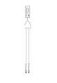
- the side view showing the wheel loader concerning one embodiment of the present invention Explanatory drawing which shows typically the whole structure of the wheel loader in the said embodiment.
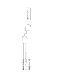
- the block diagram which shows the structure of the controller in the said embodiment.
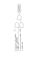
- the figure which shows the example of the torque curve in the said embodiment The figure which shows the setting conditions of the boom bottom pressure fall flag in the said embodiment.
- the figure which shows the setting conditions of the boom bottom pressure fall flag in the said embodiment The figure which shows the setting conditions of the boom bottom pressure fall flag in the said embodiment.
- the figure which shows the setting conditions of the flag under excavation in the said embodiment The figure which shows the setting conditions of the flag under excavation in the said embodiment.
- the figure which shows the setting conditions of the in-loading flag in the said embodiment The figure which shows the setting conditions of the in-loading flag in the said embodiment.
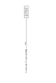
- the flowchart which shows the torque curve selection process in the said
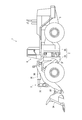
- FIG. 1 is a side view showing a wheel loader 1 according to a first embodiment of the present invention.
- the wheel loader 1 is a large wheel loader 1 used in a mine or the like.
- the wheel loader 1 includes a vehicle body 2 configured of a front vehicle body 2A and a rear vehicle body 2B.
- a hydraulic pressure constituted by a digging / loading bucket 3A, a boom 3B, a bell crank 3C, a connecting link 3D, a bucket cylinder 3E, a boom cylinder 3F, etc.
- the work machine 3 of the formula is attached.
- the rear vehicle body 2B has a rear vehicle body frame 5 formed of a thick metal plate or the like. On the front side of the rear body frame 5, a box-like cab 6 on which the operator rides is provided, and on the rear side of the rear body frame 5, an engine (not shown) and a hydraulic pump driven by the engine are mounted.
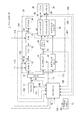
- FIG. 2 is an explanatory view schematically showing the entire configuration of the wheel loader 1.
- the wheel loader 1 includes a controller 10, an engine 11, a PTO (Power Take Off: power take-off device) 12, a traveling system 20, and a hydraulic system 30.
- the PTO 12 distributes the output of the engine 11 to the traveling system 20 and the hydraulic system 30.
- the travel system 20 is a mechanism (travel device) for causing the wheel loader 1 to travel
- the hydraulic device system 30 is a mechanism for mainly driving the work implement 3 (for example, the boom 3B or the bucket 3A).
- the traveling system 20 includes, for example, a modulation clutch (hereinafter referred to as “clutch”) 21, a torque converter 22, a transmission 23, and an axle 24.
- the clutch is abbreviated as “MOD / C”
- the torque converter is abbreviated as “T / C”
- the transmission is abbreviated as “T / M”.
- the connection or disconnection of the clutch 21 is controlled by, for example, hydraulic pressure. Specifically, when a clutch command pressure (a control signal specifying a hydraulic pressure to the clutch 21) is output from the controller 10, the clutch 21 is controlled by the hydraulic pressure specified by the control signal.
- the pressure to the clutch 21 is referred to as "clutch pressure”.
- the power output from the engine 11 is transmitted to the wheels via the clutch 21, the torque converter 22, the transmission 23 and the axle 24.
- the hydraulic system 30, for example, includes a loader pump 31, a steering pump 32, a main valve 34, a boom cylinder 3F, a bucket cylinder 3E, and a steering cylinder 36.
- the loader pump 31 is a pump for supplying hydraulic oil to the boom cylinder 3F and the bucket cylinder 3E.
- the steering pump 32 is a pump for supplying hydraulic oil to the steering cylinder 36.
- the loader pump 31 and the steering pump 32 are configured as, for example, a swash plate type hydraulic pump, and the angle of the swash plate is controlled by a control signal from the controller 10.
- the main valve 34 supplies the hydraulic fluid discharged from the loader pump 31 to the boom cylinder 3F and the bucket cylinder 3E according to the pilot pressure input from the bucket lever or the boom lever.
- the hydraulic system 30 may be equipped with another pump in place of or in addition to at least one of the loader pump 31 and the steering pump 32 described above.
- the wheel loader 1 may be provided with a pump for driving a cooling fan, a pump for lubricating the transmission 23, a pump for generating a brake pressure, and the like.
- the wheel loader 1 includes various sensors such as an engine speed sensor 41 for detecting an engine speed, a clutch pressure sensor 42 for detecting a clutch pressure, and a clutch output shaft speed for detecting an output shaft speed of the clutch 21.
- an accelerator opening sensor accelerator opening degree detector 46 constitutes an accelerator operation amount detecting means of the present invention.
- the boom bottom pressure detector 47, the boom angle detector 48, and the bucket angle detector which constitute the detection means of the present invention together with the accelerator opening degree detector 46. 49, the FNR lever operation position detector 50 is provided.
- the boom bottom pressure detector 47 is constituted by a pressure sensor provided at the bottom portion of the boom cylinder 3F, and detects the boom bottom pressure.
- the boom angle detector 48 is a device for detecting the angle of the boom 3B with respect to the ground surface, and is constituted by a potentiometer or the like provided on the rotation shaft of the boom 3B to detect the angle of the boom 3B.
- the bucket angle detector 49 is a device for detecting the angle of the bucket 3A with respect to the ground surface.
- the bucket angle detector 49 is constituted by a potentiometer or the like provided on the rotation shaft of the bell crank 3C and indirectly detects the angle of the bucket 3A.
- a potentiometer or the like may be provided on the rotation axis of the bucket 3A, and the angle of the bucket 3A may be detected indirectly from the relative relationship with the boom angle.
- the FNR lever operation position detector 50 detects the operation position of the FNR lever which selects the speed stage of the transmission (transmission) 23 from forward (F), neutral (N) and reverse (R). For example, in the case of a transmission 23 having four forward speed stages (F1 to F4), two reverse speed stages (R1 and R2) and a neutral (N), the FNR lever operating position detector 50 determines which speed by shifting the FNR lever. It detects whether a stage has been selected.
- the various states detected by the various sensors 41-45 and the detectors 46-50 are input to the controller 10 as electrical signals as indicated by dotted arrows 101-109 respectively. Further, the controller 10 transmits a control signal specifying the swash plate angle of the loader pump 31 to the loader pump 31 as indicated by a dashed dotted arrow 111, and as indicated by a dashed dotted arrow 112, the controller 10 indicates a skew of the steering pump 32.
- a control signal specifying the plate angle is transmitted to the steering pump 32, or a clutch command pressure is transmitted to the clutch 21 as indicated by an alternate long and short dash line 113, and a control signal indicating an speed stage is indicated as an alternate long and short dash line 114.
- a fuel injection amount signal corresponding to the accelerator opening in a torque curve (maximum output characteristic) described later is commanded to the engine 11.
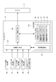
- the configuration of the controller 10 will be described based on FIG.
- the controller 10 includes a state determination unit 110, a torque curve selection unit 120, and a storage unit 130.
- the state determination means 110 determines whether digging or non-drilling is in progress based on the detection result output from each of the detectors 46 to 50, and further, during non-drilling, loading is in progress. It is determined whether or not A specific determination method of this state determination will be described later.
- the torque curve selection means 120 selects a torque curve according to the state determined by the state determination means 110.
- the storage unit 130 includes a determination value storage unit 131 and a torque curve storage unit 135. As shown in Table 1 below, the determination value storage unit 131 stores the determination value of the boom angle used by the state determination unit 110 and the determination value of the boom bottom pressure. Although the setting values of the three judgment values of the boom bottom pressure judgment values 1 to 3 are the same in Table 1 below, the setting values may be different depending on the kind of the wheel loader 1 or the like.
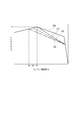
- the torque curve storage unit 135 stores one type of digging torque curve 136 and three types of non-digging torque curves 137 to 139. These torque curves 136 to 139 are set to characteristics as shown in FIG. 4, for example.
- FIG. 4 shows the engine performance defined by the engine maximum output torque T at each engine speed N for each of the torque curves 136 to 139.
- the digging torque curve 136 gives priority to power over fuel consumption, and the maximum output torque T1 that can be generated is set to be the largest value among all the torque curves 136 to 139.
- the first non-drilling torque curve 137 has the same maximum output torque as the digging torque curve 136 in a region where the engine speed N is equal to or less than the rpm N1 at which the maximum torque can be generated in the digging torque curve 136 However, in a region where the engine speed N1 is exceeded, the output torque is set to be smaller than that of the digging torque curve 136.
- the second non-drilling torque curve 138 has the same maximum output torque as the digging torque curve 136 and the non-drilling torque curve 137 in a region where the engine rotational speed N is N2 or less lower than the N1.
- the output torque is set to be smaller than the non-excavating torque curve 137 in a region higher than the engine rotational speed N2.
- the third non-drilling torque curve 139 has the same maximum output torque as the digging torque curve 136 and the non-drilling torque curves 137 and 138 in a region where the engine speed N is lower than N3 and is lower than N2 However, in a region higher than the engine rotational speed N3, the output torque is set to be smaller than that of the non-digging second torque curve 138.
- the torque curve selection means 120 selects one of the torque curves 136 to 139 stored in the torque curve storage unit 135 based on the result determined by the state determination means 110. Then, as described above, the controller 10 instructs the engine 11 a fuel ejection amount signal according to the accelerator opening detected by the accelerator opening detector 46 based on the torque curve selected by the torque curve selection means 120. Do.
- the state determination means 110 sets the values of the boom bottom pressure reduction flag, the digging flag and the loading flag based on the detection results output from the detectors 46 to 50.
- the state determination means 110 sets the boom bottom pressure reduction flag to ON when it can be determined that the boom bottom pressure is decreasing by detecting whether the boom bottom pressure is less than the determination value.
- the case where the boom angle is horizontal (0) or more and the case where the boom angle is lower than horizontal (0) and the lower limit (boom angle judgment value 1) where the bucket 3A is in contact with the ground are different. It is possible to make a decision. This is because the boom bottom determination value can be set individually in the case where the boom angle is made horizontal or more and the case where the boom angle is lower than the horizontal so that highly accurate determination can be made. In particular, in medium-to-small wheel loaders, the amount of change in boom bottom pressure during digging and non-drilling during loading etc. is small, so accurate determination can be performed by individually setting the boom bottom decision value. Can.
- the state determination unit 110 sets the boom bottom pressure reduction flag only by comparing the boom bottom pressure determination value set to the value between the boom bottom pressures at the time of digging and non-drilling and the detected boom bottom pressure. It can be set.
- the state determination unit 110 sets the boom bottom pressure reduction flag to OFF when the below-described digging flag described later is ON or the under-loading flag described later is ON.
- the boom bottom pressure reduction flag changes from OFF to ON, and the boom bottom pressure is the boom bottom pressure determination value 3 or more, and the boom angle is the boom angle determination.
- the digging flag is set to ON. If the boom angle is equal to or less than the boom angle determination value 2, it can be estimated that the bucket 3A has been moved to a height suitable for the digging operation. Also, if the boom bottom pressure reduction flag changes from OFF to ON and the boom bottom pressure is the boom bottom pressure determination value 3 or more, it can be estimated that the boom bottom pressure is increased by the digging operation. Therefore, the state determination unit 110 sets the digging flag to ON when the conditions of FIG. 6A are met.
- the state determination means 110 changes the boom bottom pressure reduction flag from OFF to ON when the digging flag is ON, or the FNR lever is other than F (forward), that is, In the case of N (Neutral) or R (Backward), the digging flag is set to OFF.
- F Forward
- the boom bottom pressure reduction flag is turned on when the digging state is the digging state in which the digging flag is ON, it is found that the digging state is released.
- the digging operation is always performed in the forward (F) state, the digging state is released also when any other than the forward (F) is selected.
- the state determination unit 110 sets the loading flag to ON when the digging flag changes from ON to OFF. Since the loading operation is performed after the digging operation, the state determination unit 110 turns on the loading flag when the digging flag is turned off.
- the state determination unit 110 sets the in-loading flag to OFF when the bucket angle detected by the bucket angle detector 49 is on the dump side (for example, -20 degrees or less).
- the loading operation is completed by approaching the dump truck and carrying out the unloading operation.
- the bucket lever is operated to the dump side, and the angle of the bucket 3A is made negative (-) to move the bucket 3A to the dump posture. For this reason, it is possible to detect that the loading operation has ended by determining whether the bucket angle is equal to or less than the set angle.
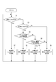
- the torque curve selection means 120 selects a torque curve based on the state of each flag determined by the state determination means 110. Specifically, the torque curve selection means 120 determines whether the digging flag is ON (step S1). The torque curve selection means 120 selects the digging torque curve 136 when the digging flag is ON (step S1: Yes) (step S2). As a result, the output torque of the engine 11 can be increased, and the work implement 3 and the like can be operated in a state suitable for excavating work.
- the torque curve selection means 120 determines whether the in-loading flag is ON (step S3).
- the torque curve selection means 120 determines that the accelerator opening detected by the accelerator opening detector 46 is larger than the first set value (90% in the present embodiment) when the loading flag is ON (step S3: Yes). It is determined (step S4). If the accelerator opening degree is larger than the first set value (step S4: Yes), the torque curve selection means 120 selects the non-excavating first torque curve 137 (step S5).
- the output torque of the engine 11 can be set lower compared to during digging, but since the operator has increased the accelerator opening (depression amount), the speed at the time of the dump approach in the state of full load It is necessary to increase the speed of the working machine 3 such as raising the boom 3B. Therefore, since the non-excavating first torque curve 137 having the highest output torque is selected among the non-excavating torque curves 137 to 139, the speed of the work implement 3 or the like during loading work can be increased, and The fuel consumption can be reduced as compared with the case where the engine 11 is controlled by the digging torque curve 136 at the time of loading work.
- step S6 determines whether the accelerator opening is larger than the second set value (80% in the present embodiment).
- step S6 selects the non-excavating second torque curve 138 when the accelerator opening is less than the first set value and greater than the second set value (step S6: Yes) (step S7).
- the operator slightly lowers the accelerator opening (depression amount)
- the work during loading work is compared with the case where the engine 11 is controlled by the digging torque curve 136 or the non-digging first torque curve 137. Although the speed of the machine 3 etc. decreases, the fuel consumption can be reduced.
- step S8 In the case of No in step S6, that is, in the case where the accelerator opening is less than the second set value and in the case of No in step S3, that is, when not digging or loading (for example, simply traveling), torque curve
- the selection means 120 selects the non-digging third torque curve 139 (step S8).
- the output torque is reduced as compared to the case where the engine 11 is controlled by the digging torque curve 136, the non-drilling first torque curve 137, and the non-drilling second torque curve 138, but the fuel consumption can be further reduced. For this reason, at the time of loading work, when it is not necessary to increase the speed of the work implement 3 so much due to the relation of the cycle time of work, it is possible to give priority to the fuel consumption.
- the engine 11 is controlled with priority given to fuel consumption. it can. Furthermore, since the torque curve is not selected according to the accelerator opening at the time of non-excavating and non-loading, when simply traveling, the torque curve is fixed and the speed can be smoothly adjusted according to the accelerator opening .
- the non-digging torque curves 137 to 139 are set to the same characteristics as the digging torque curve 136 in a region where the engine speed N is low. For this reason, the output torque of the engine 11 can be secured when working at a low engine speed N, as in the case of a dump approach in which the drilling operation is reversed once and then advanced again to load the dump truck. It is possible to prevent the deterioration of sex.
- step S3 in the embodiment when the determination processing of step S3 in the embodiment is eliminated and the digging flag is OFF (during non digging), 3 for non digging according to the accelerator opening degree.
- One of the torque curves 137 to 139 may be selected. That is, not only during loading but also when traveling alone, one of the torque curves 137 to 139 may be selected according to the accelerator opening. In this case, the determination during loading can be made unnecessary.
- the type and number of torque curves that can be selected at loading may be different from the type and number of torque curves that can be selected during non-loading, such as when traveling alone. For example, when loading, one of three types of torque curves 137 to 139 is selected according to the accelerator opening, and when not loaded, one of two types of torque curves 138, 139 is selected according to the accelerator opening. You may choose.
- each of the torque curves 136 to 139 are not limited to those represented by broken lines as exemplified in FIG. 4, and all or part of the characteristics may be curved. Furthermore, although the torque curves 136 to 139 have the same torque characteristics in the region where the engine rotational speed N is low, the torque characteristics may be made different in this region as well. In short, the digging torque curve 136 may be set with priority given to power over fuel consumption, and the non-drilling first torque curve 137, the non-drilling second torque curve 138, and the non-drilling third torque curve 139 may be In this order, the fuel consumption may be set to be improved. Furthermore, the torque curve at the time of non-digging is not limited to three types, and may be two types, or four or more types.
- the detection means is not limited to the detectors 46 to 50, and may be any means capable of determining whether or not excavation is in progress or whether or not loading is in progress. For example, one that detects a rotational difference between the input side and the output side of the torque converter 22 may be used.
- the bucket angle detector 49 is provided, and the detection value of the bucket angle detector 49 is used to determine whether or not the cargo is in progress.
- the present invention is not limited to this.
- the under-loading flag may be turned OFF when the boom bottom pressure becomes equal to or less than the third determination value.
- the third determination value may be the same value as the boom bottom pressure determination value 1 or 2 in the above embodiment or may be another value.
- the in-loading flag may be turned OFF when it is detected that the bucket lever has been operated to the dump side by a predetermined amount or more.
- the present invention is applicable to a wheel loader.
Abstract
L'invention porte sur une chargeuse sur roues, qui comprend des détecteurs (46 à 50) et une unité de commande (10). Les détecteurs (46 à 50) comprennent au moins un détecteur de degré d'ouverture de pédale d'accélérateur (46) qui détecte l'amplitude de manœuvre de la pédale d'accélérateur. L'unité de commande (10) comprend un moyen d'identification d'état (110) et un moyen de sélection de courbe de couple (120). Le moyen d'identification d'état (100) identifie si l'équipement exécute ou non une excavation, sur la base des résultats de la détection exécutée par les détecteurs (46 à 50). Si le moyen d'identification d'état (110) identifie que l'équipement est en cours d'exécution d'une excavation, le moyen de sélection de courbe de couple (120) sélectionne une courbe de couple d'excavation (136) d'un premier type. Si le moyen d'identification d'état (110) identifie que l'équipement n'est pas en cours d'exécution d'une excavation, le moyen de sélection de courbe de couple (120) sélectionne un parmi les deux ou plusieurs types de courbe de couple de non-excavation (137 à 139), en fonction de l'amplitude de manœuvre de la pédale d'accélérateur.
Priority Applications (3)
| Application Number | Priority Date | Filing Date | Title |
|---|---|---|---|
| CN201380038003.8A CN104603430B (zh) | 2012-07-24 | 2013-05-29 | 轮式装载机及轮式装载机的发动机控制方法 |
| US14/416,841 US9469973B2 (en) | 2012-07-24 | 2013-05-29 | Wheel loader and wheel loader engine control method |
| EP13822128.8A EP2868901B1 (fr) | 2012-07-24 | 2013-05-29 | Chargeuse sur roues et procédé de commande de moteur de chargeuse sur roues |
Applications Claiming Priority (2)
| Application Number | Priority Date | Filing Date | Title |
|---|---|---|---|
| JP2012-163575 | 2012-07-24 | ||
| JP2012163575A JP5996314B2 (ja) | 2012-07-24 | 2012-07-24 | ホイールローダおよびホイールローダのエンジン制御方法 |
Publications (1)
| Publication Number | Publication Date |
|---|---|
| WO2014017166A1 true WO2014017166A1 (fr) | 2014-01-30 |
Family
ID=49996984
Family Applications (1)
| Application Number | Title | Priority Date | Filing Date |
|---|---|---|---|
| PCT/JP2013/064935 WO2014017166A1 (fr) | 2012-07-24 | 2013-05-29 | Chargeuse sur roues et procédé de commande de moteur de chargeuse sur roues |
Country Status (5)
| Country | Link |
|---|---|
| US (1) | US9469973B2 (fr) |
| EP (1) | EP2868901B1 (fr) |
| JP (1) | JP5996314B2 (fr) |
| CN (1) | CN104603430B (fr) |
| WO (1) | WO2014017166A1 (fr) |
Cited By (2)
| Publication number | Priority date | Publication date | Assignee | Title |
|---|---|---|---|---|
| US9689319B2 (en) | 2014-09-12 | 2017-06-27 | Caterpillar Inc. | Power system having efficiency-based speed control |
| US9969402B2 (en) | 2015-09-28 | 2018-05-15 | Caterpillar Inc. | Transmission system having efficiency-based speed control |
Families Citing this family (12)
| Publication number | Priority date | Publication date | Assignee | Title |
|---|---|---|---|---|
| KR101950041B1 (ko) * | 2012-12-18 | 2019-04-22 | 두산인프라코어 주식회사 | 산업용 차량의 엔진 제어 방법 및 장치 |
| EP2966283B1 (fr) * | 2013-03-06 | 2017-11-15 | Hitachi Construction Machinery Co., Ltd. | Engin de chantier |
| EP3093400B1 (fr) * | 2015-05-12 | 2018-08-01 | Doosan Infracore Co., Ltd. | Procédé de commande d'une chargeuse à roues |
| US10362738B2 (en) * | 2015-09-10 | 2019-07-30 | Komatsu Ltd. | Work vehicle |
| CN113073692B (zh) * | 2015-09-16 | 2023-07-04 | 住友重机械工业株式会社 | 挖土机以及挖土机用控制装置 |
| US10037634B2 (en) * | 2016-03-22 | 2018-07-31 | Deere & Company | System and method for idle state determination |
| US10059341B2 (en) | 2016-06-17 | 2018-08-28 | Caterpillar Inc. | Control strategy for reduced fuel consumption in machine and powertrain system with same |
| JP6586406B2 (ja) * | 2016-09-30 | 2019-10-02 | 日立建機株式会社 | 作業車両 |
| CN109532841B (zh) * | 2018-11-21 | 2021-07-13 | 广西柳工机械股份有限公司 | 装载机发动机功率曲线自动选择方法 |
| US10927523B2 (en) | 2019-02-19 | 2021-02-23 | Caterpillar Inc. | Cross-members and pin couplers for lift arms |
| EP4155466A1 (fr) | 2021-09-24 | 2023-03-29 | Volvo Construction Equipment AB | Procédé de commande de machine de travail, système de commande et machine de travail |
| IT202100026672A1 (it) * | 2021-10-18 | 2023-04-18 | Cnh Ind Italia Spa | Metodo e sistema di controllo di una trasmissione elettrica di una pala meccanica |
Citations (4)
| Publication number | Priority date | Publication date | Assignee | Title |
|---|---|---|---|---|
| WO2005024208A1 (fr) | 2003-09-02 | 2005-03-17 | Komatsu Ltd. | Procede et dispositif de commande de la puissance de sortie d'un moteur pour machine de travail |
| WO2009116250A1 (fr) | 2008-03-21 | 2009-09-24 | 株式会社小松製作所 | Machine entraînée par moteur, dispositif de commande pour machine entraînée par moteur, et procédé de commande de caractéristiques de puissance maximum de moteur |
| JP2011202531A (ja) * | 2010-03-24 | 2011-10-13 | Komatsu Ltd | 作業車両及び作業車両の制御方法 |
| JP2011236759A (ja) * | 2010-05-07 | 2011-11-24 | Komatsu Ltd | 作業車両及び作業車両の制御方法 |
Family Cites Families (6)
| Publication number | Priority date | Publication date | Assignee | Title |
|---|---|---|---|---|
| JP2986471B2 (ja) * | 1999-01-22 | 1999-12-06 | 株式会社小松製作所 | 建設機械の制御装置 |
| US7058502B2 (en) | 2003-11-20 | 2006-06-06 | International Engine Intellectual Property Company, Llc | Torque speed control authority for an engine having an all-speed governor |
| EP2211042B1 (fr) * | 2007-10-24 | 2016-12-14 | KCM Corporation | Dispositif de commande de moteur pour véhicule de travail |
| US8214115B2 (en) * | 2008-12-17 | 2012-07-03 | Caterpillar Inc. | System and method of changing engine performance curves to manage heat generation |
| JP2010180848A (ja) * | 2009-02-09 | 2010-08-19 | Tcm Corp | 作業車両の原動機制御装置 |
| US8316983B2 (en) * | 2009-04-09 | 2012-11-27 | Komatsu Ltd. | Construction vehicle |
-
2012
- 2012-07-24 JP JP2012163575A patent/JP5996314B2/ja active Active
-
2013
- 2013-05-29 US US14/416,841 patent/US9469973B2/en active Active
- 2013-05-29 WO PCT/JP2013/064935 patent/WO2014017166A1/fr active Application Filing
- 2013-05-29 EP EP13822128.8A patent/EP2868901B1/fr active Active
- 2013-05-29 CN CN201380038003.8A patent/CN104603430B/zh active Active
Patent Citations (4)
| Publication number | Priority date | Publication date | Assignee | Title |
|---|---|---|---|---|
| WO2005024208A1 (fr) | 2003-09-02 | 2005-03-17 | Komatsu Ltd. | Procede et dispositif de commande de la puissance de sortie d'un moteur pour machine de travail |
| WO2009116250A1 (fr) | 2008-03-21 | 2009-09-24 | 株式会社小松製作所 | Machine entraînée par moteur, dispositif de commande pour machine entraînée par moteur, et procédé de commande de caractéristiques de puissance maximum de moteur |
| JP2011202531A (ja) * | 2010-03-24 | 2011-10-13 | Komatsu Ltd | 作業車両及び作業車両の制御方法 |
| JP2011236759A (ja) * | 2010-05-07 | 2011-11-24 | Komatsu Ltd | 作業車両及び作業車両の制御方法 |
Cited By (2)
| Publication number | Priority date | Publication date | Assignee | Title |
|---|---|---|---|---|
| US9689319B2 (en) | 2014-09-12 | 2017-06-27 | Caterpillar Inc. | Power system having efficiency-based speed control |
| US9969402B2 (en) | 2015-09-28 | 2018-05-15 | Caterpillar Inc. | Transmission system having efficiency-based speed control |
Also Published As
| Publication number | Publication date |
|---|---|
| EP2868901A1 (fr) | 2015-05-06 |
| EP2868901A4 (fr) | 2016-03-16 |
| JP2014025345A (ja) | 2014-02-06 |
| US9469973B2 (en) | 2016-10-18 |
| EP2868901B1 (fr) | 2017-05-17 |
| CN104603430B (zh) | 2017-03-08 |
| CN104603430A (zh) | 2015-05-06 |
| US20150204053A1 (en) | 2015-07-23 |
| JP5996314B2 (ja) | 2016-09-21 |
Similar Documents
| Publication | Publication Date | Title |
|---|---|---|
| WO2014017166A1 (fr) | Chargeuse sur roues et procédé de commande de moteur de chargeuse sur roues | |
| US9085874B2 (en) | Working vehicle and hydraulic fluid amount control method for working vehicle | |
| EP1830053B1 (fr) | Dispositif de commande pour un vehicule mobile en fonctionnement | |
| JP5192605B1 (ja) | ホイールローダ | |
| JP5228132B1 (ja) | ホイールローダ | |
| JP5292635B2 (ja) | 作業車両の駆動力制御装置および駆動力制御方法 | |
| JP5204837B2 (ja) | 作業車両、作業車両の制御装置、及び作業車両の制御方法 | |
| JP4493990B2 (ja) | 走行式油圧作業機 | |
| WO2009116249A1 (fr) | Véhicule de travail, dispositif de commande pour véhicule de travail et procédé de contrôle de la quantité d'huile de fonctionnement pour véhicule de travail | |
| JP2010223416A (ja) | 建設車両 | |
| EP1918463A2 (fr) | Système de contrôle pour moteur d'engins de construction | |
| US11391017B2 (en) | Wheel loader | |
| US10619330B2 (en) | Multiple level work hydraulics anti-stall | |
| JP5106662B1 (ja) | バックホーローダ | |
| WO2013136537A1 (fr) | Véhiculede travail et procédé de commande de véhicule de travail | |
| WO2010052831A1 (fr) | Véhicule de travail | |
| JPWO2019064527A1 (ja) | ホイールローダ | |
| KR102452805B1 (ko) | 휠 로더의 제어 방법 및 시스템 | |
| JP4376018B2 (ja) | 作業車両の制御装置 | |
| JP2024059231A (ja) | 作業機械、及び、作業機械を制御するための方法 | |
| JP2005023870A (ja) | 作業車両の制御装置 |
Legal Events
| Date | Code | Title | Description |
|---|---|---|---|
| 121 | Ep: the epo has been informed by wipo that ep was designated in this application |
Ref document number: 13822128 Country of ref document: EP Kind code of ref document: A1 |
|
| REEP | Request for entry into the european phase |
Ref document number: 2013822128 Country of ref document: EP |
|
| WWE | Wipo information: entry into national phase |
Ref document number: 2013822128 Country of ref document: EP |
|
| WWE | Wipo information: entry into national phase |
Ref document number: 14416841 Country of ref document: US |
|
| NENP | Non-entry into the national phase |
Ref country code: DE |