WO2014017166A1 - Wheel loader and wheel loader engine control method - Google Patents
Wheel loader and wheel loader engine control method Download PDFInfo
- Publication number
- WO2014017166A1 WO2014017166A1 PCT/JP2013/064935 JP2013064935W WO2014017166A1 WO 2014017166 A1 WO2014017166 A1 WO 2014017166A1 JP 2013064935 W JP2013064935 W JP 2013064935W WO 2014017166 A1 WO2014017166 A1 WO 2014017166A1
- Authority
- WO
- WIPO (PCT)
- Prior art keywords
- torque
- torque curve
- digging
- engine
- determined
- Prior art date
Links
Images


Classifications
-
- E—FIXED CONSTRUCTIONS
- E02—HYDRAULIC ENGINEERING; FOUNDATIONS; SOIL SHIFTING
- E02F—DREDGING; SOIL-SHIFTING
- E02F9/00—Component parts of dredgers or soil-shifting machines, not restricted to one of the kinds covered by groups E02F3/00 - E02F7/00
- E02F9/20—Drives; Control devices
- E02F9/22—Hydraulic or pneumatic drives
- E02F9/2246—Control of prime movers, e.g. depending on the hydraulic load of work tools
-
- E—FIXED CONSTRUCTIONS
- E02—HYDRAULIC ENGINEERING; FOUNDATIONS; SOIL SHIFTING
- E02F—DREDGING; SOIL-SHIFTING
- E02F3/00—Dredgers; Soil-shifting machines
- E02F3/04—Dredgers; Soil-shifting machines mechanically-driven
- E02F3/28—Dredgers; Soil-shifting machines mechanically-driven with digging tools mounted on a dipper- or bucket-arm, i.e. there is either one arm or a pair of arms, e.g. dippers, buckets
- E02F3/283—Dredgers; Soil-shifting machines mechanically-driven with digging tools mounted on a dipper- or bucket-arm, i.e. there is either one arm or a pair of arms, e.g. dippers, buckets with a single arm pivoted directly on the chassis
-
- E—FIXED CONSTRUCTIONS
- E02—HYDRAULIC ENGINEERING; FOUNDATIONS; SOIL SHIFTING
- E02F—DREDGING; SOIL-SHIFTING
- E02F9/00—Component parts of dredgers or soil-shifting machines, not restricted to one of the kinds covered by groups E02F3/00 - E02F7/00
- E02F9/20—Drives; Control devices
- E02F9/2058—Electric or electro-mechanical or mechanical control devices of vehicle sub-units
- E02F9/2062—Control of propulsion units
- E02F9/2066—Control of propulsion units of the type combustion engines
-
- F—MECHANICAL ENGINEERING; LIGHTING; HEATING; WEAPONS; BLASTING
- F02—COMBUSTION ENGINES; HOT-GAS OR COMBUSTION-PRODUCT ENGINE PLANTS
- F02D—CONTROLLING COMBUSTION ENGINES
- F02D29/00—Controlling engines, such controlling being peculiar to the devices driven thereby, the devices being other than parts or accessories essential to engine operation, e.g. controlling of engines by signals external thereto
- F02D29/02—Controlling engines, such controlling being peculiar to the devices driven thereby, the devices being other than parts or accessories essential to engine operation, e.g. controlling of engines by signals external thereto peculiar to engines driving vehicles; peculiar to engines driving variable pitch propellers
-
- F—MECHANICAL ENGINEERING; LIGHTING; HEATING; WEAPONS; BLASTING
- F02—COMBUSTION ENGINES; HOT-GAS OR COMBUSTION-PRODUCT ENGINE PLANTS
- F02D—CONTROLLING COMBUSTION ENGINES
- F02D29/00—Controlling engines, such controlling being peculiar to the devices driven thereby, the devices being other than parts or accessories essential to engine operation, e.g. controlling of engines by signals external thereto
- F02D29/04—Controlling engines, such controlling being peculiar to the devices driven thereby, the devices being other than parts or accessories essential to engine operation, e.g. controlling of engines by signals external thereto peculiar to engines driving pumps
-
- F—MECHANICAL ENGINEERING; LIGHTING; HEATING; WEAPONS; BLASTING
- F02—COMBUSTION ENGINES; HOT-GAS OR COMBUSTION-PRODUCT ENGINE PLANTS
- F02D—CONTROLLING COMBUSTION ENGINES
- F02D41/00—Electrical control of supply of combustible mixture or its constituents
- F02D41/008—Controlling each cylinder individually
- F02D41/0085—Balancing of cylinder outputs, e.g. speed, torque or air-fuel ratio
-
- F—MECHANICAL ENGINEERING; LIGHTING; HEATING; WEAPONS; BLASTING
- F02—COMBUSTION ENGINES; HOT-GAS OR COMBUSTION-PRODUCT ENGINE PLANTS
- F02D—CONTROLLING COMBUSTION ENGINES
- F02D2200/00—Input parameters for engine control
- F02D2200/02—Input parameters for engine control the parameters being related to the engine
- F02D2200/10—Parameters related to the engine output, e.g. engine torque or engine speed
-
- F—MECHANICAL ENGINEERING; LIGHTING; HEATING; WEAPONS; BLASTING
- F02—COMBUSTION ENGINES; HOT-GAS OR COMBUSTION-PRODUCT ENGINE PLANTS
- F02D—CONTROLLING COMBUSTION ENGINES
- F02D2700/00—Mechanical control of speed or power of a single cylinder piston engine
- F02D2700/07—Automatic control systems according to one of the preceding groups in combination with control of the mechanism receiving the engine power
Definitions
- the present invention relates to a wheel loader and an engine control method for the wheel loader.
- engine torque is automatically switched to reduce fuel consumption. For example, it is determined whether the wheel loader is digging or climbing uphill, and if digging or climbing uphill, the engine is set to the high output mode, otherwise the engine is low powered It is known to set the mode to realize fuel consumption reduction (see, for example, Patent Document 1).
- the load of the working machine pump and the load of the torque converter are calculated, and the maximum output characteristic of the engine such that the maximum output torque that can be output by the engine at the current engine speed is equal to or higher than the calculated load torque. It is known to variably control (torque curve) (see, for example, Patent Document 2).
- a large force is required not only during digging but also during the loading process of loading a bucket and approaching a dump truck while raising a boom.
- the torque curve selected in this loading process is set to a torque curve that increases the maximum output torque so that the dump truck can be approached while raising the boom at the maximum speed with the bucket fully loaded. Then, when the load of the bucket is small, or when the work is performed at a low speed for raising the boom, the output torque becomes excessive with respect to the load, and the fuel consumption reduction effect is reduced.
- the boom can not be lifted because the boom can not raise the boom when the bucket is fully loaded, or the boom can be lifted There is a problem that the speed is low and the work efficiency is reduced.
- An object of the present invention is to provide a wheel loader and an engine control method for the wheel loader that can improve at least the fuel efficiency reduction effect during the loading process and can also prevent the decrease in work efficiency.
- a wheel loader comprises an engine, a working machine and a traveling device driven by the engine, detection means for detecting the states of the working machine and the traveling device, and a plurality of torques having different torque characteristics of the engine. And a controller for storing a curve and selecting a torque curve for control of the engine based on the detection result detected by the detection means, the torque curve including one kind of excavating torque curve and two or more kinds of torque curves.
- a non-excavating torque curve is provided, and the detection means at least includes an accelerator operation amount detection means for detecting an accelerator operation amount, and the controller determines whether or not excavation is being performed based on the detection result of the detection means.
- the digging torque curve is selected, and it is determined that it is not digging.
- a torque curve selection means for selecting one of two or more types of non-excavating torque curves in accordance with the accelerator operation amount detected by the accelerator operation amount detection means. I assume.
- the engine can be controlled in a mode suitable for the excavation operation.
- the torque curve is selected according to the accelerator operation amount from the two or more types of non-excavating torque curves at the time of non-excavating such as loading work, etc.
- the working machine can be operated at an appropriate speed according to the operator's operation.
- fuel consumption can be reduced as compared with the case of performing work at the time of non-digging using the torque curve for digging.
- a wheel loader comprises an engine, a working machine and a traveling device driven by the engine, detection means for detecting the states of the working machine and the traveling device, and a plurality of torques having different torque characteristics of the engine. And a controller for storing a curve and selecting a torque curve for control of the engine based on the detection result detected by the detection means, the torque curve including one kind of excavating torque curve and two or more kinds of torque curves.
- a non-excavating torque curve is provided, and the detection means at least includes an accelerator operation amount detection means for detecting an accelerator operation amount, and the controller is based on the detection result of the detection means whether State determination means for determining whether or not loading is performed, and when it is determined that the loading is being performed, the digging torque curve When it is determined that loading is selected, one of two or more types of non-digging torque curves is selected according to the accelerator operating amount detected by the accelerator operating amount detecting means, and excavation is performed. And a torque curve selection means for selecting a torque curve having the smallest possible torque curve among two or more types of non-excavating torque curves when it is determined that neither time nor loading is determined. Do.
- the engine can be controlled in a mode suitable for the drilling operation. Further, since the torque curve is selected according to the accelerator operation amount from the two or more types of non-excavating torque curves at the time of loading, the working machine can be operated at an appropriate speed according to the operator's operation, and The fuel consumption can be reduced as compared with the case of carrying out the loading work using the digging torque curve.
- the wheel loader according to the third invention is the wheel loader according to the first invention or the second invention, wherein the torque curve selected when the accelerator operation amount detected by the accelerator operation amount detecting means is the largest among the non-digging torque curves is
- the rotational speed region lower than the maximum torque generation rotational speed of the excavating torque curve is set to the same torque characteristic as the excavating torque curve, and is higher than the maximum torque generating rotational speed of the excavating torque curve
- the torque characteristic is set such that the generated torque is smaller than that of the digging torque curve in at least a part of the region.
- the non-digging torque curve selected when the accelerator operation amount is maximum is the same as the digging torque curve in the rotation speed region lower than the maximum torque generation rotational speed of the digging torque curve. It is set to torque characteristics. For this reason, it is possible to reduce the fuel consumption while securing the speed of the working machine at the time of approach to the dump truck including the operation in a relatively low rotation speed area to move backward again after loading and move forward again. it can.
- an engine control method for a wheel loader comprising: an engine; a working machine and a traveling device driven by the engine; detection means for detecting states of the working machine and the traveling device;
- An engine control method for a wheel loader comprising: storage means for storing a plurality of different torque curves, wherein the torque curve comprises one kind of digging torque curve and two or more kinds of non-digging torque curves, Based on the detection result of the detection means, it is determined whether or not excavation is in progress, and if it is determined that it is in excavation, the torque curve for excavation is selected and it is determined that it is not in excavation.
- the present invention is characterized in that an amount of operation of an accelerator is detected, and one of two or more types of non-excavating torque curves is selected according to the amount of accelerator operation.
- an engine control method for a wheel loader comprising: an engine; a working machine and a traveling device driven by the engine; detection means for detecting states of the working machine and the traveling device;
- An engine control method for a wheel loader comprising: storage means for storing a plurality of different torque curves, wherein the torque curve comprises one kind of digging torque curve and two or more kinds of non-digging torque curves, Based on the detection result of the detection means, it is determined whether or not excavation is carried out and whether or not loading is carried out, and when it is discriminated that it is excavated, the torque curve for excavation is selected.
- the operation amount of the accelerator is detected, and one of two or more types of non-digging torque curves is selected according to the accelerator operation amount. If it is determined that neither time cargo even when drilling, characterized in that two or more of the torque curve which may occur among the non-drilling torque curve selects the smallest torque curve.
- the same action and effect as those of the first aspect of the invention can be obtained. Further, according to the fifth aspect, it is possible to receive the same action and effect as the second aspect.
- the side view showing the wheel loader concerning one embodiment of the present invention Explanatory drawing which shows typically the whole structure of the wheel loader in the said embodiment.
- the block diagram which shows the structure of the controller in the said embodiment.
- the figure which shows the example of the torque curve in the said embodiment The figure which shows the setting conditions of the boom bottom pressure fall flag in the said embodiment.
- the figure which shows the setting conditions of the boom bottom pressure fall flag in the said embodiment The figure which shows the setting conditions of the boom bottom pressure fall flag in the said embodiment.
- the figure which shows the setting conditions of the flag under excavation in the said embodiment The figure which shows the setting conditions of the flag under excavation in the said embodiment.
- the figure which shows the setting conditions of the in-loading flag in the said embodiment The figure which shows the setting conditions of the in-loading flag in the said embodiment.
- the flowchart which shows the torque curve selection process in the said
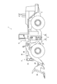
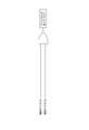
- FIG. 1 is a side view showing a wheel loader 1 according to a first embodiment of the present invention.
- the wheel loader 1 is a large wheel loader 1 used in a mine or the like.
- the wheel loader 1 includes a vehicle body 2 configured of a front vehicle body 2A and a rear vehicle body 2B.
- a hydraulic pressure constituted by a digging / loading bucket 3A, a boom 3B, a bell crank 3C, a connecting link 3D, a bucket cylinder 3E, a boom cylinder 3F, etc.
- the work machine 3 of the formula is attached.
- the rear vehicle body 2B has a rear vehicle body frame 5 formed of a thick metal plate or the like. On the front side of the rear body frame 5, a box-like cab 6 on which the operator rides is provided, and on the rear side of the rear body frame 5, an engine (not shown) and a hydraulic pump driven by the engine are mounted.
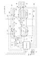
- FIG. 2 is an explanatory view schematically showing the entire configuration of the wheel loader 1.
- the wheel loader 1 includes a controller 10, an engine 11, a PTO (Power Take Off: power take-off device) 12, a traveling system 20, and a hydraulic system 30.
- the PTO 12 distributes the output of the engine 11 to the traveling system 20 and the hydraulic system 30.
- the travel system 20 is a mechanism (travel device) for causing the wheel loader 1 to travel
- the hydraulic device system 30 is a mechanism for mainly driving the work implement 3 (for example, the boom 3B or the bucket 3A).
- the traveling system 20 includes, for example, a modulation clutch (hereinafter referred to as “clutch”) 21, a torque converter 22, a transmission 23, and an axle 24.
- the clutch is abbreviated as “MOD / C”
- the torque converter is abbreviated as “T / C”
- the transmission is abbreviated as “T / M”.
- the connection or disconnection of the clutch 21 is controlled by, for example, hydraulic pressure. Specifically, when a clutch command pressure (a control signal specifying a hydraulic pressure to the clutch 21) is output from the controller 10, the clutch 21 is controlled by the hydraulic pressure specified by the control signal.
- the pressure to the clutch 21 is referred to as "clutch pressure”.
- the power output from the engine 11 is transmitted to the wheels via the clutch 21, the torque converter 22, the transmission 23 and the axle 24.
- the hydraulic system 30, for example, includes a loader pump 31, a steering pump 32, a main valve 34, a boom cylinder 3F, a bucket cylinder 3E, and a steering cylinder 36.
- the loader pump 31 is a pump for supplying hydraulic oil to the boom cylinder 3F and the bucket cylinder 3E.
- the steering pump 32 is a pump for supplying hydraulic oil to the steering cylinder 36.
- the loader pump 31 and the steering pump 32 are configured as, for example, a swash plate type hydraulic pump, and the angle of the swash plate is controlled by a control signal from the controller 10.
- the main valve 34 supplies the hydraulic fluid discharged from the loader pump 31 to the boom cylinder 3F and the bucket cylinder 3E according to the pilot pressure input from the bucket lever or the boom lever.
- the hydraulic system 30 may be equipped with another pump in place of or in addition to at least one of the loader pump 31 and the steering pump 32 described above.
- the wheel loader 1 may be provided with a pump for driving a cooling fan, a pump for lubricating the transmission 23, a pump for generating a brake pressure, and the like.
- the wheel loader 1 includes various sensors such as an engine speed sensor 41 for detecting an engine speed, a clutch pressure sensor 42 for detecting a clutch pressure, and a clutch output shaft speed for detecting an output shaft speed of the clutch 21.
- an accelerator opening sensor accelerator opening degree detector 46 constitutes an accelerator operation amount detecting means of the present invention.
- the boom bottom pressure detector 47, the boom angle detector 48, and the bucket angle detector which constitute the detection means of the present invention together with the accelerator opening degree detector 46. 49, the FNR lever operation position detector 50 is provided.
- the boom bottom pressure detector 47 is constituted by a pressure sensor provided at the bottom portion of the boom cylinder 3F, and detects the boom bottom pressure.
- the boom angle detector 48 is a device for detecting the angle of the boom 3B with respect to the ground surface, and is constituted by a potentiometer or the like provided on the rotation shaft of the boom 3B to detect the angle of the boom 3B.
- the bucket angle detector 49 is a device for detecting the angle of the bucket 3A with respect to the ground surface.
- the bucket angle detector 49 is constituted by a potentiometer or the like provided on the rotation shaft of the bell crank 3C and indirectly detects the angle of the bucket 3A.
- a potentiometer or the like may be provided on the rotation axis of the bucket 3A, and the angle of the bucket 3A may be detected indirectly from the relative relationship with the boom angle.
- the FNR lever operation position detector 50 detects the operation position of the FNR lever which selects the speed stage of the transmission (transmission) 23 from forward (F), neutral (N) and reverse (R). For example, in the case of a transmission 23 having four forward speed stages (F1 to F4), two reverse speed stages (R1 and R2) and a neutral (N), the FNR lever operating position detector 50 determines which speed by shifting the FNR lever. It detects whether a stage has been selected.
- the various states detected by the various sensors 41-45 and the detectors 46-50 are input to the controller 10 as electrical signals as indicated by dotted arrows 101-109 respectively. Further, the controller 10 transmits a control signal specifying the swash plate angle of the loader pump 31 to the loader pump 31 as indicated by a dashed dotted arrow 111, and as indicated by a dashed dotted arrow 112, the controller 10 indicates a skew of the steering pump 32.
- a control signal specifying the plate angle is transmitted to the steering pump 32, or a clutch command pressure is transmitted to the clutch 21 as indicated by an alternate long and short dash line 113, and a control signal indicating an speed stage is indicated as an alternate long and short dash line 114.
- a fuel injection amount signal corresponding to the accelerator opening in a torque curve (maximum output characteristic) described later is commanded to the engine 11.
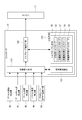
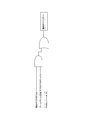
- the configuration of the controller 10 will be described based on FIG.
- the controller 10 includes a state determination unit 110, a torque curve selection unit 120, and a storage unit 130.
- the state determination means 110 determines whether digging or non-drilling is in progress based on the detection result output from each of the detectors 46 to 50, and further, during non-drilling, loading is in progress. It is determined whether or not A specific determination method of this state determination will be described later.
- the torque curve selection means 120 selects a torque curve according to the state determined by the state determination means 110.
- the storage unit 130 includes a determination value storage unit 131 and a torque curve storage unit 135. As shown in Table 1 below, the determination value storage unit 131 stores the determination value of the boom angle used by the state determination unit 110 and the determination value of the boom bottom pressure. Although the setting values of the three judgment values of the boom bottom pressure judgment values 1 to 3 are the same in Table 1 below, the setting values may be different depending on the kind of the wheel loader 1 or the like.
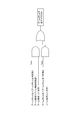
- the torque curve storage unit 135 stores one type of digging torque curve 136 and three types of non-digging torque curves 137 to 139. These torque curves 136 to 139 are set to characteristics as shown in FIG. 4, for example.
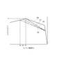
- FIG. 4 shows the engine performance defined by the engine maximum output torque T at each engine speed N for each of the torque curves 136 to 139.
- the digging torque curve 136 gives priority to power over fuel consumption, and the maximum output torque T1 that can be generated is set to be the largest value among all the torque curves 136 to 139.
- the first non-drilling torque curve 137 has the same maximum output torque as the digging torque curve 136 in a region where the engine speed N is equal to or less than the rpm N1 at which the maximum torque can be generated in the digging torque curve 136 However, in a region where the engine speed N1 is exceeded, the output torque is set to be smaller than that of the digging torque curve 136.
- the second non-drilling torque curve 138 has the same maximum output torque as the digging torque curve 136 and the non-drilling torque curve 137 in a region where the engine rotational speed N is N2 or less lower than the N1.
- the output torque is set to be smaller than the non-excavating torque curve 137 in a region higher than the engine rotational speed N2.
- the third non-drilling torque curve 139 has the same maximum output torque as the digging torque curve 136 and the non-drilling torque curves 137 and 138 in a region where the engine speed N is lower than N3 and is lower than N2 However, in a region higher than the engine rotational speed N3, the output torque is set to be smaller than that of the non-digging second torque curve 138.
- the torque curve selection means 120 selects one of the torque curves 136 to 139 stored in the torque curve storage unit 135 based on the result determined by the state determination means 110. Then, as described above, the controller 10 instructs the engine 11 a fuel ejection amount signal according to the accelerator opening detected by the accelerator opening detector 46 based on the torque curve selected by the torque curve selection means 120. Do.
- the state determination means 110 sets the values of the boom bottom pressure reduction flag, the digging flag and the loading flag based on the detection results output from the detectors 46 to 50.
- the state determination means 110 sets the boom bottom pressure reduction flag to ON when it can be determined that the boom bottom pressure is decreasing by detecting whether the boom bottom pressure is less than the determination value.
- the case where the boom angle is horizontal (0) or more and the case where the boom angle is lower than horizontal (0) and the lower limit (boom angle judgment value 1) where the bucket 3A is in contact with the ground are different. It is possible to make a decision. This is because the boom bottom determination value can be set individually in the case where the boom angle is made horizontal or more and the case where the boom angle is lower than the horizontal so that highly accurate determination can be made. In particular, in medium-to-small wheel loaders, the amount of change in boom bottom pressure during digging and non-drilling during loading etc. is small, so accurate determination can be performed by individually setting the boom bottom decision value. Can.
- the state determination unit 110 sets the boom bottom pressure reduction flag only by comparing the boom bottom pressure determination value set to the value between the boom bottom pressures at the time of digging and non-drilling and the detected boom bottom pressure. It can be set.
- the state determination unit 110 sets the boom bottom pressure reduction flag to OFF when the below-described digging flag described later is ON or the under-loading flag described later is ON.
- the boom bottom pressure reduction flag changes from OFF to ON, and the boom bottom pressure is the boom bottom pressure determination value 3 or more, and the boom angle is the boom angle determination.
- the digging flag is set to ON. If the boom angle is equal to or less than the boom angle determination value 2, it can be estimated that the bucket 3A has been moved to a height suitable for the digging operation. Also, if the boom bottom pressure reduction flag changes from OFF to ON and the boom bottom pressure is the boom bottom pressure determination value 3 or more, it can be estimated that the boom bottom pressure is increased by the digging operation. Therefore, the state determination unit 110 sets the digging flag to ON when the conditions of FIG. 6A are met.
- the state determination means 110 changes the boom bottom pressure reduction flag from OFF to ON when the digging flag is ON, or the FNR lever is other than F (forward), that is, In the case of N (Neutral) or R (Backward), the digging flag is set to OFF.
- F Forward
- the boom bottom pressure reduction flag is turned on when the digging state is the digging state in which the digging flag is ON, it is found that the digging state is released.
- the digging operation is always performed in the forward (F) state, the digging state is released also when any other than the forward (F) is selected.
- the state determination unit 110 sets the loading flag to ON when the digging flag changes from ON to OFF. Since the loading operation is performed after the digging operation, the state determination unit 110 turns on the loading flag when the digging flag is turned off.
- the state determination unit 110 sets the in-loading flag to OFF when the bucket angle detected by the bucket angle detector 49 is on the dump side (for example, -20 degrees or less).
- the loading operation is completed by approaching the dump truck and carrying out the unloading operation.
- the bucket lever is operated to the dump side, and the angle of the bucket 3A is made negative (-) to move the bucket 3A to the dump posture. For this reason, it is possible to detect that the loading operation has ended by determining whether the bucket angle is equal to or less than the set angle.
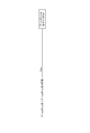
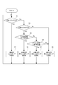
- the torque curve selection means 120 selects a torque curve based on the state of each flag determined by the state determination means 110. Specifically, the torque curve selection means 120 determines whether the digging flag is ON (step S1). The torque curve selection means 120 selects the digging torque curve 136 when the digging flag is ON (step S1: Yes) (step S2). As a result, the output torque of the engine 11 can be increased, and the work implement 3 and the like can be operated in a state suitable for excavating work.
- the torque curve selection means 120 determines whether the in-loading flag is ON (step S3).
- the torque curve selection means 120 determines that the accelerator opening detected by the accelerator opening detector 46 is larger than the first set value (90% in the present embodiment) when the loading flag is ON (step S3: Yes). It is determined (step S4). If the accelerator opening degree is larger than the first set value (step S4: Yes), the torque curve selection means 120 selects the non-excavating first torque curve 137 (step S5).
- the output torque of the engine 11 can be set lower compared to during digging, but since the operator has increased the accelerator opening (depression amount), the speed at the time of the dump approach in the state of full load It is necessary to increase the speed of the working machine 3 such as raising the boom 3B. Therefore, since the non-excavating first torque curve 137 having the highest output torque is selected among the non-excavating torque curves 137 to 139, the speed of the work implement 3 or the like during loading work can be increased, and The fuel consumption can be reduced as compared with the case where the engine 11 is controlled by the digging torque curve 136 at the time of loading work.
- step S6 determines whether the accelerator opening is larger than the second set value (80% in the present embodiment).
- step S6 selects the non-excavating second torque curve 138 when the accelerator opening is less than the first set value and greater than the second set value (step S6: Yes) (step S7).
- the operator slightly lowers the accelerator opening (depression amount)
- the work during loading work is compared with the case where the engine 11 is controlled by the digging torque curve 136 or the non-digging first torque curve 137. Although the speed of the machine 3 etc. decreases, the fuel consumption can be reduced.
- step S8 In the case of No in step S6, that is, in the case where the accelerator opening is less than the second set value and in the case of No in step S3, that is, when not digging or loading (for example, simply traveling), torque curve
- the selection means 120 selects the non-digging third torque curve 139 (step S8).
- the output torque is reduced as compared to the case where the engine 11 is controlled by the digging torque curve 136, the non-drilling first torque curve 137, and the non-drilling second torque curve 138, but the fuel consumption can be further reduced. For this reason, at the time of loading work, when it is not necessary to increase the speed of the work implement 3 so much due to the relation of the cycle time of work, it is possible to give priority to the fuel consumption.
- the engine 11 is controlled with priority given to fuel consumption. it can. Furthermore, since the torque curve is not selected according to the accelerator opening at the time of non-excavating and non-loading, when simply traveling, the torque curve is fixed and the speed can be smoothly adjusted according to the accelerator opening .
- the non-digging torque curves 137 to 139 are set to the same characteristics as the digging torque curve 136 in a region where the engine speed N is low. For this reason, the output torque of the engine 11 can be secured when working at a low engine speed N, as in the case of a dump approach in which the drilling operation is reversed once and then advanced again to load the dump truck. It is possible to prevent the deterioration of sex.
- step S3 in the embodiment when the determination processing of step S3 in the embodiment is eliminated and the digging flag is OFF (during non digging), 3 for non digging according to the accelerator opening degree.
- One of the torque curves 137 to 139 may be selected. That is, not only during loading but also when traveling alone, one of the torque curves 137 to 139 may be selected according to the accelerator opening. In this case, the determination during loading can be made unnecessary.
- the type and number of torque curves that can be selected at loading may be different from the type and number of torque curves that can be selected during non-loading, such as when traveling alone. For example, when loading, one of three types of torque curves 137 to 139 is selected according to the accelerator opening, and when not loaded, one of two types of torque curves 138, 139 is selected according to the accelerator opening. You may choose.
- each of the torque curves 136 to 139 are not limited to those represented by broken lines as exemplified in FIG. 4, and all or part of the characteristics may be curved. Furthermore, although the torque curves 136 to 139 have the same torque characteristics in the region where the engine rotational speed N is low, the torque characteristics may be made different in this region as well. In short, the digging torque curve 136 may be set with priority given to power over fuel consumption, and the non-drilling first torque curve 137, the non-drilling second torque curve 138, and the non-drilling third torque curve 139 may be In this order, the fuel consumption may be set to be improved. Furthermore, the torque curve at the time of non-digging is not limited to three types, and may be two types, or four or more types.
- the detection means is not limited to the detectors 46 to 50, and may be any means capable of determining whether or not excavation is in progress or whether or not loading is in progress. For example, one that detects a rotational difference between the input side and the output side of the torque converter 22 may be used.
- the bucket angle detector 49 is provided, and the detection value of the bucket angle detector 49 is used to determine whether or not the cargo is in progress.
- the present invention is not limited to this.
- the under-loading flag may be turned OFF when the boom bottom pressure becomes equal to or less than the third determination value.
- the third determination value may be the same value as the boom bottom pressure determination value 1 or 2 in the above embodiment or may be another value.
- the in-loading flag may be turned OFF when it is detected that the bucket lever has been operated to the dump side by a predetermined amount or more.
- the present invention is applicable to a wheel loader.
Abstract
A wheel loader comprises detectors (46 to 50) and a controller (10). The detectors (46 to 50) comprise at least an accelerator pedal degree of opening detector (46) that detects the amount of operation of the accelerator pedal. The controller (10) comprises state identification means (110) and torque curve selection means (120). The state identification means (110) identifies whether or not the equipment is performing excavation, based on the results of detection carried out by the detectors (46 to 50). If the state identification means (110) identifies that the equipment is performing excavation, the torque curve selection means (120) selects an excavation torque curve (136) of a first type. If the state identification means (110) identifies that the equipment is not performing excavation, the torque curve selection means (120) selects one of two or more types of non-excavation torque curve (137 to 139), in accordance with the operating amount of the accelerator pedal.
Description
本発明は、ホイールローダおよびホイールローダのエンジン制御方法に関する。
The present invention relates to a wheel loader and an engine control method for the wheel loader.
最新のホイールローダでは、燃費低減のために、エンジントルクを自動的に切り替えている。例えば、ホイールローダにおいて、掘削中であるか、登坂走行中であるかを判別し、掘削中あるいは登坂走行中であればエンジンを高出力モードに設定し、それ以外の場合にはエンジンを低出力モードに設定して燃費低減を実現するものが知られている(例えば、特許文献1参照)。
また、作業機ポンプの負荷やトルクコンバータの負荷を算出し、現在のエンジン回転数においてエンジンが出力可能な最大出力トルクが、前記算出された負荷トルク以上となるように、前記エンジンの最大出力特性(トルクカーブ)を可変制御するものが知られている(例えば、特許文献2参照)。 In the latest wheel loaders, engine torque is automatically switched to reduce fuel consumption. For example, it is determined whether the wheel loader is digging or climbing uphill, and if digging or climbing uphill, the engine is set to the high output mode, otherwise the engine is low powered It is known to set the mode to realize fuel consumption reduction (see, for example, Patent Document 1).
In addition, the load of the working machine pump and the load of the torque converter are calculated, and the maximum output characteristic of the engine such that the maximum output torque that can be output by the engine at the current engine speed is equal to or higher than the calculated load torque. It is known to variably control (torque curve) (see, for example, Patent Document 2).
しかしながら、前記特許文献1,2の技術では、掘削中や積荷中など、現在の状態がどの工程にあるかを判定し、その工程の種類によってエンジンのトルクカーブを切り替えるものであり、1つの工程に対応して選択されるトルクカーブは1つのみである。このため、燃費削減効果を高めることに限界があるという問題がある。
However, in the techniques of Patent Documents 1 and 2, it is determined which process the current state is in, such as digging or loading, and the torque curve of the engine is switched depending on the type of the process. Only one torque curve is selected corresponding to. For this reason, there is a problem that there is a limit in enhancing the fuel consumption reduction effect.
特に、鉱山などで使用される大型のホイールローダの場合、掘削中だけでなく、バケットに荷を満載してブームを上げながらダンプトラックにアプローチする積荷工程の際にも大きな力を必要とする。
このような積荷工程で選択されるトルクカーブを、バケットに荷を満載にした状態で、かつ、最大速度でブームを上げながらダンプトラックにアプローチできるように、最大出力トルクが大きくなるトルクカーブに設定すると、バケットの荷が少ない場合や、ブームを上げる速度を低速にして作業する際に、負荷に対して過大な出力トルクとなり、燃費削減効果が小さくなるという問題がある。
逆に、燃費削減効果を高めるために、積荷工程で選択されるトルクカーブを低く設定すると、バケットに荷を満載にした際にブームを上げる力が足りずにブームが持ち上がらない、あるいはブームの上昇速度が遅くなって作業効率が低下するという問題がある。 In particular, in the case of a large wheel loader used in a mine or the like, a large force is required not only during digging but also during the loading process of loading a bucket and approaching a dump truck while raising a boom.
The torque curve selected in this loading process is set to a torque curve that increases the maximum output torque so that the dump truck can be approached while raising the boom at the maximum speed with the bucket fully loaded. Then, when the load of the bucket is small, or when the work is performed at a low speed for raising the boom, the output torque becomes excessive with respect to the load, and the fuel consumption reduction effect is reduced.
Conversely, if the torque curve selected in the loading process is set low to enhance the fuel consumption reduction effect, the boom can not be lifted because the boom can not raise the boom when the bucket is fully loaded, or the boom can be lifted There is a problem that the speed is low and the work efficiency is reduced.
本発明の目的は、少なくとも積荷工程時の燃費削減効果を高めることができ、かつ、作業効率の低下も防止できるホイールローダおよびホイールローダのエンジン制御方法を提供することにある。
An object of the present invention is to provide a wheel loader and an engine control method for the wheel loader that can improve at least the fuel efficiency reduction effect during the loading process and can also prevent the decrease in work efficiency.
第1発明に係るホイールローダは、エンジンと、前記エンジンにより駆動される作業機および走行装置と、前記作業機および走行装置の状態を検知する検知手段と、前記エンジンのトルク特性の異なる複数のトルクカーブを記憶し、前記検知手段で検知した検知結果に基づいて前記エンジンの制御用のトルクカーブを選択するコントローラとを備え、前記トルクカーブは、1種類の掘削用トルクカーブと、2種類以上の非掘削用トルクカーブを備え、前記検知手段は、アクセル操作量を検知するアクセル操作量検知手段を少なくとも備え、前記コントローラは、前記検知手段の検知結果に基づき、掘削時であるか否かを判別する状態判別手段と、掘削時であると判別された場合には、前記掘削用トルクカーブを選択し、非掘削時であると判別された場合には、前記アクセル操作量検知手段によって検知されるアクセル操作量に応じて2種類以上の非掘削用トルクカーブのうちの1つを選択するトルクカーブ選択手段と、を備えることを特徴とする。
A wheel loader according to a first aspect of the present invention comprises an engine, a working machine and a traveling device driven by the engine, detection means for detecting the states of the working machine and the traveling device, and a plurality of torques having different torque characteristics of the engine. And a controller for storing a curve and selecting a torque curve for control of the engine based on the detection result detected by the detection means, the torque curve including one kind of excavating torque curve and two or more kinds of torque curves. A non-excavating torque curve is provided, and the detection means at least includes an accelerator operation amount detection means for detecting an accelerator operation amount, and the controller determines whether or not excavation is being performed based on the detection result of the detection means. If it is determined that it is in the state of digging, the digging torque curve is selected, and it is determined that it is not digging. And a torque curve selection means for selecting one of two or more types of non-excavating torque curves in accordance with the accelerator operation amount detected by the accelerator operation amount detection means. I assume.
第1発明によれば、掘削時には、掘削用に設定されたトルクカーブを選択しているので、エンジンを掘削作業に適したモードで制御できる。また、積荷作業などの非掘削時には、2種類以上の非掘削用トルクカーブの中から、アクセル操作量に応じてトルクカーブを選択しているので、オペレータの操作に応じて適切な速度で作業機を作動でき、かつ、掘削用トルクカーブを用いて非掘削時の作業を行う場合に比べて燃費を低減できる。
According to the first aspect of the invention, since the torque curve set for excavation is selected at the time of excavation, the engine can be controlled in a mode suitable for the excavation operation. In addition, since the torque curve is selected according to the accelerator operation amount from the two or more types of non-excavating torque curves at the time of non-excavating such as loading work, etc., the working machine can be operated at an appropriate speed according to the operator's operation. In addition, fuel consumption can be reduced as compared with the case of performing work at the time of non-digging using the torque curve for digging.
第2発明に係るホイールローダは、エンジンと、前記エンジンにより駆動される作業機および走行装置と、前記作業機および走行装置の状態を検知する検知手段と、前記エンジンのトルク特性の異なる複数のトルクカーブを記憶し、前記検知手段で検知した検知結果に基づいて前記エンジンの制御用のトルクカーブを選択するコントローラとを備え、前記トルクカーブは、1種類の掘削用トルクカーブと、2種類以上の非掘削用トルクカーブを備え、前記検知手段は、アクセル操作量を検知するアクセル操作量検知手段を少なくとも備え、前記コントローラは、前記検知手段の検知結果に基づき、掘削時であるか否か、および、積荷時であるか否かを判別する状態判別手段と、掘削時であると判別された場合には、前記掘削用トルクカーブを選択し、積荷時であると判別された場合には、前記アクセル操作量検知手段によって検知されるアクセル操作量に応じて2種類以上の非掘削用トルクカーブのうちの1つを選択し、掘削時でも積荷時でもないと判断された場合には、2種類以上の非掘削用トルクカーブのうち発生しうるトルクカーブが最も小さいトルクカーブを選択するトルクカーブ選択手段と、を備えることを特徴とする。
A wheel loader according to a second aspect of the present invention comprises an engine, a working machine and a traveling device driven by the engine, detection means for detecting the states of the working machine and the traveling device, and a plurality of torques having different torque characteristics of the engine. And a controller for storing a curve and selecting a torque curve for control of the engine based on the detection result detected by the detection means, the torque curve including one kind of excavating torque curve and two or more kinds of torque curves. A non-excavating torque curve is provided, and the detection means at least includes an accelerator operation amount detection means for detecting an accelerator operation amount, and the controller is based on the detection result of the detection means whether State determination means for determining whether or not loading is performed, and when it is determined that the loading is being performed, the digging torque curve When it is determined that loading is selected, one of two or more types of non-digging torque curves is selected according to the accelerator operating amount detected by the accelerator operating amount detecting means, and excavation is performed. And a torque curve selection means for selecting a torque curve having the smallest possible torque curve among two or more types of non-excavating torque curves when it is determined that neither time nor loading is determined. Do.
第2発明によれば、掘削時には、掘削用に設定されたトルクカーブを選択しているので、エンジンを掘削作業に適したモードで制御できる。また、積荷時には、2種類以上の非掘削用トルクカーブの中から、アクセル操作量に応じてトルクカーブを選択しているので、オペレータの操作に応じて適切な速度で作業機を作動でき、かつ、掘削用トルクカーブを用いて積荷作業を行う場合に比べて燃費を低減できる。
According to the second aspect of the invention, since the torque curve set for drilling is selected at the time of drilling, the engine can be controlled in a mode suitable for the drilling operation. Further, since the torque curve is selected according to the accelerator operation amount from the two or more types of non-excavating torque curves at the time of loading, the working machine can be operated at an appropriate speed according to the operator's operation, and The fuel consumption can be reduced as compared with the case of carrying out the loading work using the digging torque curve.
第3発明に係るホイールローダは、第1発明又は第2発明において、前記非掘削用トルクカーブのうち、前記アクセル操作量検知手段によって検知されるアクセル操作量が最大の時に選択されるトルクカーブは、前記掘削用トルクカーブの最大トルク発生回転数よりも低い回転数領域では、前記掘削用トルクカーブと同じトルク特性に設定され、前記掘削用トルクカーブの最大トルク発生回転数よりも高い回転数領域の少なくとも一部の領域では、前記掘削用トルクカーブよりも発生トルクが小さいトルク特性に設定されていることを特徴とする。
The wheel loader according to the third invention is the wheel loader according to the first invention or the second invention, wherein the torque curve selected when the accelerator operation amount detected by the accelerator operation amount detecting means is the largest among the non-digging torque curves is The rotational speed region lower than the maximum torque generation rotational speed of the excavating torque curve is set to the same torque characteristic as the excavating torque curve, and is higher than the maximum torque generating rotational speed of the excavating torque curve The torque characteristic is set such that the generated torque is smaller than that of the digging torque curve in at least a part of the region.
第3発明によれば、アクセル操作量が最大の時に選択される非掘削用トルクカーブは、前記掘削用トルクカーブの最大トルク発生回転数よりも低い回転数領域では、前記掘削用トルクカーブと同じトルク特性に設定されている。このため、積荷作業後に一旦後進し、再度前進するために比較的回転数が低い領域での動作も含まれるダンプトラックへのアプローチ時に、作業機の速度を確保しつつ、燃費を低減することができる。
According to the third aspect of the invention, the non-digging torque curve selected when the accelerator operation amount is maximum is the same as the digging torque curve in the rotation speed region lower than the maximum torque generation rotational speed of the digging torque curve. It is set to torque characteristics. For this reason, it is possible to reduce the fuel consumption while securing the speed of the working machine at the time of approach to the dump truck including the operation in a relatively low rotation speed area to move backward again after loading and move forward again. it can.
第4発明に係るホイールローダのエンジン制御方法は、エンジンと、前記エンジンにより駆動される作業機および走行装置と、前記作業機および走行装置の状態を検知する検知手段と、前記エンジンのトルク特性の異なる複数のトルクカーブを記憶する記憶手段とを備えたホイールローダのエンジン制御方法であって、前記トルクカーブは、1種類の掘削用トルクカーブと、2種類以上の非掘削用トルクカーブを備え、前記検知手段の検知結果に基づき、掘削時であるか否かを判別し、掘削時であると判別した場合には、前記掘削用トルクカーブを選択し、非掘削時であると判別した場合には、アクセルの操作量を検出し、このアクセル操作量に応じて2種類以上の非掘削用トルクカーブのうちの1つを選択することを特徴とする。
According to a fourth aspect of the present invention, there is provided an engine control method for a wheel loader, comprising: an engine; a working machine and a traveling device driven by the engine; detection means for detecting states of the working machine and the traveling device; An engine control method for a wheel loader comprising: storage means for storing a plurality of different torque curves, wherein the torque curve comprises one kind of digging torque curve and two or more kinds of non-digging torque curves, Based on the detection result of the detection means, it is determined whether or not excavation is in progress, and if it is determined that it is in excavation, the torque curve for excavation is selected and it is determined that it is not in excavation. The present invention is characterized in that an amount of operation of an accelerator is detected, and one of two or more types of non-excavating torque curves is selected according to the amount of accelerator operation.
第5発明に係るホイールローダのエンジン制御方法は、エンジンと、前記エンジンにより駆動される作業機および走行装置と、前記作業機および走行装置の状態を検知する検知手段と、前記エンジンのトルク特性の異なる複数のトルクカーブを記憶する記憶手段とを備えたホイールローダのエンジン制御方法であって、前記トルクカーブは、1種類の掘削用トルクカーブと、2種類以上の非掘削用トルクカーブを備え、前記検知手段の検知結果に基づき、掘削時であるか否か、および、積荷時であるか否かを判別し、掘削時であると判別した場合には、前記掘削用トルクカーブを選択し、積荷時であると判別した場合には、アクセルの操作量を検出し、このアクセル操作量に応じて2種類以上の非掘削用トルクカーブのうちの1つを選択し、掘削時でも積荷時でもないと判断された場合には、2種類以上の非掘削用トルクカーブのうち発生しうるトルクカーブが最も小さいトルクカーブを選択することを特徴とする。
According to a fifth aspect of the present invention, there is provided an engine control method for a wheel loader, comprising: an engine; a working machine and a traveling device driven by the engine; detection means for detecting states of the working machine and the traveling device; An engine control method for a wheel loader comprising: storage means for storing a plurality of different torque curves, wherein the torque curve comprises one kind of digging torque curve and two or more kinds of non-digging torque curves, Based on the detection result of the detection means, it is determined whether or not excavation is carried out and whether or not loading is carried out, and when it is discriminated that it is excavated, the torque curve for excavation is selected. When it is determined that loading is performed, the operation amount of the accelerator is detected, and one of two or more types of non-digging torque curves is selected according to the accelerator operation amount. If it is determined that neither time cargo even when drilling, characterized in that two or more of the torque curve which may occur among the non-drilling torque curve selects the smallest torque curve.
第4発明によれば、第1発明と同様の作用及び効果を享受できる。また、第5発明によれば、第2発明と同様の作用及び効果を享受できる。
According to the fourth aspect of the invention, the same action and effect as those of the first aspect of the invention can be obtained. Further, according to the fifth aspect, it is possible to receive the same action and effect as the second aspect.
以下、本発明の実施の形態を図面に基づいて説明する。
[全体構成]
図1は、本発明の第1実施形態に係るホイールローダ1を示す側面図である。ホイールローダ1は、鉱山等で使用される大型のホイールローダ1である。
ホイールローダ1は、前部車体2Aと後部車体2Bとで構成される車体2を備えている。前部車体2Aの前方(図1中の左方)には、掘削・積込用のバケット3A、ブーム3B、ベルクランク3C、連結リンク3D、バケットシリンダ3E、ブームシリンダ3F等で構成される油圧式の作業機3が取り付けられている。 Hereinafter, embodiments of the present invention will be described based on the drawings.
[overall structure]
FIG. 1 is a side view showing awheel loader 1 according to a first embodiment of the present invention. The wheel loader 1 is a large wheel loader 1 used in a mine or the like.
Thewheel loader 1 includes a vehicle body 2 configured of a front vehicle body 2A and a rear vehicle body 2B. In front of the front vehicle body 2A (left side in FIG. 1), a hydraulic pressure constituted by a digging / loading bucket 3A, a boom 3B, a bell crank 3C, a connecting link 3D, a bucket cylinder 3E, a boom cylinder 3F, etc. The work machine 3 of the formula is attached.
[全体構成]
図1は、本発明の第1実施形態に係るホイールローダ1を示す側面図である。ホイールローダ1は、鉱山等で使用される大型のホイールローダ1である。
ホイールローダ1は、前部車体2Aと後部車体2Bとで構成される車体2を備えている。前部車体2Aの前方(図1中の左方)には、掘削・積込用のバケット3A、ブーム3B、ベルクランク3C、連結リンク3D、バケットシリンダ3E、ブームシリンダ3F等で構成される油圧式の作業機3が取り付けられている。 Hereinafter, embodiments of the present invention will be described based on the drawings.
[overall structure]
FIG. 1 is a side view showing a
The
後部車体2Bは、厚板の金属板等で構成された後部車体フレーム5を有している。後部車体フレーム5の前側には、オペレータが乗り込む箱状のキャブ6が設けられ、後部車体フレーム5の後側には、図示しないエンジンや、エンジンによって駆動される油圧ポンプ等が搭載されている。
The rear vehicle body 2B has a rear vehicle body frame 5 formed of a thick metal plate or the like. On the front side of the rear body frame 5, a box-like cab 6 on which the operator rides is provided, and on the rear side of the rear body frame 5, an engine (not shown) and a hydraulic pump driven by the engine are mounted.
図2は、ホイールローダ1の全体構成を模式的に示す説明図である。ホイールローダ1は、コントローラ10と、エンジン11と、PTO(Power Take Off:動力取出装置)12と、走行系20と、油圧装置系30とを備えている。
PTO12は、エンジン11の出力を走行系20及び油圧装置系30に分配する。走行系20は、ホイールローダ1を走行させるための機構(走行装置)であり、油圧装置系30は、主に作業機3(例えばブーム3Bやバケット3A)を駆動するための機構である。 FIG. 2 is an explanatory view schematically showing the entire configuration of thewheel loader 1. The wheel loader 1 includes a controller 10, an engine 11, a PTO (Power Take Off: power take-off device) 12, a traveling system 20, and a hydraulic system 30.
ThePTO 12 distributes the output of the engine 11 to the traveling system 20 and the hydraulic system 30. The travel system 20 is a mechanism (travel device) for causing the wheel loader 1 to travel, and the hydraulic device system 30 is a mechanism for mainly driving the work implement 3 (for example, the boom 3B or the bucket 3A).
PTO12は、エンジン11の出力を走行系20及び油圧装置系30に分配する。走行系20は、ホイールローダ1を走行させるための機構(走行装置)であり、油圧装置系30は、主に作業機3(例えばブーム3Bやバケット3A)を駆動するための機構である。 FIG. 2 is an explanatory view schematically showing the entire configuration of the
The
走行系20は、例えば、モジュレーションクラッチ(以下、「クラッチ」と呼ぶ)21と、トルクコンバータ22と、トランスミッション23と、アクスル24とを備えている。なお、図2では、クラッチを「MOD/C」、トルクコンバータを「T/C」、トランスミッションを「T/M」とそれぞれ略記する。
クラッチ21の接続や切り離しは、例えば、油圧によって制御される。具体的には、コントローラ10からクラッチ指令圧(クラッチ21に対する油圧を指定した制御信号)が出力されると、その制御信号で指定されている油圧で、クラッチ21が制御される。以下、クラッチ21に対する圧力を、「クラッチ圧」と言う。
エンジン11から出力された動力は、クラッチ21、トルクコンバータ22、トランスミッション23及びアクスル24を介して、車輪に伝達される。 The travelingsystem 20 includes, for example, a modulation clutch (hereinafter referred to as “clutch”) 21, a torque converter 22, a transmission 23, and an axle 24. In FIG. 2, the clutch is abbreviated as "MOD / C", the torque converter is abbreviated as "T / C", and the transmission is abbreviated as "T / M".
The connection or disconnection of the clutch 21 is controlled by, for example, hydraulic pressure. Specifically, when a clutch command pressure (a control signal specifying a hydraulic pressure to the clutch 21) is output from thecontroller 10, the clutch 21 is controlled by the hydraulic pressure specified by the control signal. Hereinafter, the pressure to the clutch 21 is referred to as "clutch pressure".
The power output from theengine 11 is transmitted to the wheels via the clutch 21, the torque converter 22, the transmission 23 and the axle 24.
クラッチ21の接続や切り離しは、例えば、油圧によって制御される。具体的には、コントローラ10からクラッチ指令圧(クラッチ21に対する油圧を指定した制御信号)が出力されると、その制御信号で指定されている油圧で、クラッチ21が制御される。以下、クラッチ21に対する圧力を、「クラッチ圧」と言う。
エンジン11から出力された動力は、クラッチ21、トルクコンバータ22、トランスミッション23及びアクスル24を介して、車輪に伝達される。 The traveling
The connection or disconnection of the clutch 21 is controlled by, for example, hydraulic pressure. Specifically, when a clutch command pressure (a control signal specifying a hydraulic pressure to the clutch 21) is output from the
The power output from the
油圧装置系30は、例えば、ローダポンプ31と、ステアリングポンプ32と、メインバルブ34と、ブームシリンダ3Fと、バケットシリンダ3Eと、ステアリングシリンダ36とを備える。
The hydraulic system 30, for example, includes a loader pump 31, a steering pump 32, a main valve 34, a boom cylinder 3F, a bucket cylinder 3E, and a steering cylinder 36.
ローダポンプ31は、ブームシリンダ3Fおよびバケットシリンダ3Eに作動油を供給するためのポンプである。ステアリングポンプ32は、ステアリングシリンダ36に作動油を供給するためのポンプである。
ローダポンプ31およびステアリングポンプ32は、例えば斜板型油圧ポンプとして構成され、斜板の角度は、コントローラ10からの制御信号により制御される。 Theloader pump 31 is a pump for supplying hydraulic oil to the boom cylinder 3F and the bucket cylinder 3E. The steering pump 32 is a pump for supplying hydraulic oil to the steering cylinder 36.
Theloader pump 31 and the steering pump 32 are configured as, for example, a swash plate type hydraulic pump, and the angle of the swash plate is controlled by a control signal from the controller 10.
ローダポンプ31およびステアリングポンプ32は、例えば斜板型油圧ポンプとして構成され、斜板の角度は、コントローラ10からの制御信号により制御される。 The
The
メインバルブ34は、バケットレバーまたはブームレバーから入力されるパイロット圧に応じて、ローダポンプ31から吐出される作動油を、ブームシリンダ3Fやバケットシリンダ3Eに供給する。
The main valve 34 supplies the hydraulic fluid discharged from the loader pump 31 to the boom cylinder 3F and the bucket cylinder 3E according to the pilot pressure input from the bucket lever or the boom lever.
油圧装置系30には、上述したローダポンプ31、ステアリングポンプ32の少なくとも一つに代えて、または加えて、別のポンプが備えられても良い。例えば、ホイールローダ1には、冷却ファンを駆動するためのポンプや、トランスミッション23の潤滑のためのポンプや、ブレーキ圧を生成するためのポンプなどが備えられても良い。
The hydraulic system 30 may be equipped with another pump in place of or in addition to at least one of the loader pump 31 and the steering pump 32 described above. For example, the wheel loader 1 may be provided with a pump for driving a cooling fan, a pump for lubricating the transmission 23, a pump for generating a brake pressure, and the like.
ホイールローダ1には、種々のセンサとして、例えば、エンジン回転数を検出するエンジン回転数センサ41、クラッチ圧を検出するクラッチ圧センサ42、クラッチ21の出力軸回転数を検出するクラッチ出力軸回転数センサ43、トランスミッション23の出力軸回転数を検出するT/M出力回転数センサ44、ローダポンプ油圧を検出するローダポンプ油圧センサ45、および、アクセルペダル15の操作量(以下、「アクセル開度」と言う)を検出するアクセル開度検出器(アクセル開度センサ)46が設けられている。なお、このアクセル開度検出器46によって、本発明のアクセル操作量検知手段が構成されている。
The wheel loader 1 includes various sensors such as an engine speed sensor 41 for detecting an engine speed, a clutch pressure sensor 42 for detecting a clutch pressure, and a clutch output shaft speed for detecting an output shaft speed of the clutch 21. Sensor 43, T / M output rotational speed sensor 44 for detecting output shaft rotational speed of transmission 23, loader pump hydraulic pressure sensor 45 for detecting loader pump hydraulic pressure, and operation amount of accelerator pedal 15 (hereinafter referred to as "accelerator opening degree" And an accelerator opening sensor (accelerator opening sensor). The accelerator opening degree detector 46 constitutes an accelerator operation amount detecting means of the present invention.
[検知手段]
さらに、本実施形態では、図2,3に示すように、前記アクセル開度検出器46と共に、本発明の検知手段を構成するブームボトム圧検出器47、ブーム角度検出器48、バケット角度検出器49、FNRレバー操作位置検出器50を備えている。
ブームボトム圧検出器47は、ブームシリンダ3Fのボトム部分に設けられた圧力センサで構成され、ブームボトム圧を検出する。
ブーム角度検出器48は、地表面に対するブーム3Bの角度を検出するための装置であり、ブーム3Bの回転軸に設けられるポテンショメータ等で構成されており、ブーム3Bの角度を検出する。 [Detection means]
Furthermore, in the present embodiment, as shown in FIGS. 2 and 3, the boombottom pressure detector 47, the boom angle detector 48, and the bucket angle detector which constitute the detection means of the present invention together with the accelerator opening degree detector 46. 49, the FNR lever operation position detector 50 is provided.
The boombottom pressure detector 47 is constituted by a pressure sensor provided at the bottom portion of the boom cylinder 3F, and detects the boom bottom pressure.
Theboom angle detector 48 is a device for detecting the angle of the boom 3B with respect to the ground surface, and is constituted by a potentiometer or the like provided on the rotation shaft of the boom 3B to detect the angle of the boom 3B.
さらに、本実施形態では、図2,3に示すように、前記アクセル開度検出器46と共に、本発明の検知手段を構成するブームボトム圧検出器47、ブーム角度検出器48、バケット角度検出器49、FNRレバー操作位置検出器50を備えている。
ブームボトム圧検出器47は、ブームシリンダ3Fのボトム部分に設けられた圧力センサで構成され、ブームボトム圧を検出する。
ブーム角度検出器48は、地表面に対するブーム3Bの角度を検出するための装置であり、ブーム3Bの回転軸に設けられるポテンショメータ等で構成されており、ブーム3Bの角度を検出する。 [Detection means]
Furthermore, in the present embodiment, as shown in FIGS. 2 and 3, the boom
The boom
The
バケット角度検出器49は、地表面に対するバケット3Aの角度を検出するための装置であり、ベルクランク3Cの回転軸に設けられるポテンショメータ等で構成され、バケット3Aの角度を間接的に検出する。なお、バケット角度検出器49としては、バケット3Aの回転軸にポテンショメータ等を設けて構成し、ブーム角度との相対関係から間接的にバケット3Aの角度を検出してもよい。
The bucket angle detector 49 is a device for detecting the angle of the bucket 3A with respect to the ground surface. The bucket angle detector 49 is constituted by a potentiometer or the like provided on the rotation shaft of the bell crank 3C and indirectly detects the angle of the bucket 3A. As the bucket angle detector 49, a potentiometer or the like may be provided on the rotation axis of the bucket 3A, and the angle of the bucket 3A may be detected indirectly from the relative relationship with the boom angle.
FNRレバー操作位置検出器50は、トランスミッション(変速機)23の速度段を、前進(F)、ニュートラル(N)、後進(R)から選択するFNRレバーの操作位置を検出する。例えば、前進4速度段(F1~F4)、後進2速度段(R1,R2)およびニュートラル(N)を有するトランスミッション23の場合、FNRレバー操作位置検出器50は、FNRレバーのシフト操作によりどの速度段が選択されたかを検出する。
The FNR lever operation position detector 50 detects the operation position of the FNR lever which selects the speed stage of the transmission (transmission) 23 from forward (F), neutral (N) and reverse (R). For example, in the case of a transmission 23 having four forward speed stages (F1 to F4), two reverse speed stages (R1 and R2) and a neutral (N), the FNR lever operating position detector 50 determines which speed by shifting the FNR lever. It detects whether a stage has been selected.
上記各種センサ41~45や検出器46~50により検出された各種状態は、点線矢印101~109にそれぞれ示すように、電気信号としてコントローラ10に入力される。
また、コントローラ10は、一点鎖線矢印111に示すように、ローダポンプ31の斜板角度を指定した制御信号をローダポンプ31に送信したり、一点鎖線矢印112に示すように、ステアリングポンプ32の斜板角度を指定した制御信号をステアリングポンプ32に送信したり、一点鎖線113に示すように、クラッチ指令圧をクラッチ21に送信したり、一点鎖線114に示すように、速度段を指定した制御信号をトランスミッション23に送信したり、一点鎖線115に示すように、後述するトルクカーブ(最大出力特性)におけるアクセル開度に応じた燃料噴射量信号をエンジン11に指令する。 The various states detected by the various sensors 41-45 and the detectors 46-50 are input to thecontroller 10 as electrical signals as indicated by dotted arrows 101-109 respectively.
Further, thecontroller 10 transmits a control signal specifying the swash plate angle of the loader pump 31 to the loader pump 31 as indicated by a dashed dotted arrow 111, and as indicated by a dashed dotted arrow 112, the controller 10 indicates a skew of the steering pump 32. A control signal specifying the plate angle is transmitted to the steering pump 32, or a clutch command pressure is transmitted to the clutch 21 as indicated by an alternate long and short dash line 113, and a control signal indicating an speed stage is indicated as an alternate long and short dash line 114. Is transmitted to the transmission 23, or, as shown by the alternate long and short dash line 115, a fuel injection amount signal corresponding to the accelerator opening in a torque curve (maximum output characteristic) described later is commanded to the engine 11.
また、コントローラ10は、一点鎖線矢印111に示すように、ローダポンプ31の斜板角度を指定した制御信号をローダポンプ31に送信したり、一点鎖線矢印112に示すように、ステアリングポンプ32の斜板角度を指定した制御信号をステアリングポンプ32に送信したり、一点鎖線113に示すように、クラッチ指令圧をクラッチ21に送信したり、一点鎖線114に示すように、速度段を指定した制御信号をトランスミッション23に送信したり、一点鎖線115に示すように、後述するトルクカーブ(最大出力特性)におけるアクセル開度に応じた燃料噴射量信号をエンジン11に指令する。 The various states detected by the various sensors 41-45 and the detectors 46-50 are input to the
Further, the
[コントローラの構成]
コントローラ10の構成について、図3に基づいて説明する。
コントローラ10は、状態判別手段110と、トルクカーブ選択手段120と、記憶手段130とを備える。
状態判別手段110は、前記各検出器46~50から出力される検出結果に基づいて、掘削中であるか非掘削中であるかを判別し、さらに、非掘削中である場合に、積荷中であるか否かを判別する。この状態判別の具体的な判別方法は後述する。 Controller Configuration
The configuration of thecontroller 10 will be described based on FIG.
Thecontroller 10 includes a state determination unit 110, a torque curve selection unit 120, and a storage unit 130.
The state determination means 110 determines whether digging or non-drilling is in progress based on the detection result output from each of thedetectors 46 to 50, and further, during non-drilling, loading is in progress. It is determined whether or not A specific determination method of this state determination will be described later.
コントローラ10の構成について、図3に基づいて説明する。
コントローラ10は、状態判別手段110と、トルクカーブ選択手段120と、記憶手段130とを備える。
状態判別手段110は、前記各検出器46~50から出力される検出結果に基づいて、掘削中であるか非掘削中であるかを判別し、さらに、非掘削中である場合に、積荷中であるか否かを判別する。この状態判別の具体的な判別方法は後述する。 Controller Configuration
The configuration of the
The
The state determination means 110 determines whether digging or non-drilling is in progress based on the detection result output from each of the
トルクカーブ選択手段120は、状態判別手段110で判別された状態に応じて、トルクカーブを選択する。
The torque curve selection means 120 selects a torque curve according to the state determined by the state determination means 110.
記憶手段130は、判定値記憶部131と、トルクカーブ記憶部135とを備える。
判定値記憶部131には、下記表1に示すように、状態判別手段110で用いられるブーム角度の判定値と、ブームボトム圧の判定値が記憶される。なお、下記表1では、ブームボトム圧判定値1~3の3種類の判定値の設定値が同一であるが、ホイールローダ1の種類などによっては、これらの設定値を異なる値としてもよい。 Thestorage unit 130 includes a determination value storage unit 131 and a torque curve storage unit 135.
As shown in Table 1 below, the determinationvalue storage unit 131 stores the determination value of the boom angle used by the state determination unit 110 and the determination value of the boom bottom pressure. Although the setting values of the three judgment values of the boom bottom pressure judgment values 1 to 3 are the same in Table 1 below, the setting values may be different depending on the kind of the wheel loader 1 or the like.
判定値記憶部131には、下記表1に示すように、状態判別手段110で用いられるブーム角度の判定値と、ブームボトム圧の判定値が記憶される。なお、下記表1では、ブームボトム圧判定値1~3の3種類の判定値の設定値が同一であるが、ホイールローダ1の種類などによっては、これらの設定値を異なる値としてもよい。 The
As shown in Table 1 below, the determination

トルクカーブ記憶部135には、1種類の掘削用トルクカーブ136と、3種類の非掘削用トルクカーブ137~139とが記憶されている。
これらのトルクカーブ136~139は、例えば、図4に示すような特性に設定されている。図4は、各エンジン回転数Nでのエンジン最大出力トルクTで定義されるエンジン性能を、各トルクカーブ136~139毎に示したものである。 The torquecurve storage unit 135 stores one type of digging torque curve 136 and three types of non-digging torque curves 137 to 139.
These torque curves 136 to 139 are set to characteristics as shown in FIG. 4, for example. FIG. 4 shows the engine performance defined by the engine maximum output torque T at each engine speed N for each of the torque curves 136 to 139.
これらのトルクカーブ136~139は、例えば、図4に示すような特性に設定されている。図4は、各エンジン回転数Nでのエンジン最大出力トルクTで定義されるエンジン性能を、各トルクカーブ136~139毎に示したものである。 The torque
These torque curves 136 to 139 are set to characteristics as shown in FIG. 4, for example. FIG. 4 shows the engine performance defined by the engine maximum output torque T at each engine speed N for each of the torque curves 136 to 139.
掘削用トルクカーブ136は、燃費よりもパワーを優先したものであり、発生しうる最大出力トルクT1が、すべてのトルクカーブ136~139の中で最も大きな値となるように設定されている。
非掘削用第1トルクカーブ137は、エンジン回転数Nが掘削用トルクカーブ136における最大トルクを発生し得る回転数N1以下の領域では、前記掘削用トルクカーブ136と同じ最大出力トルクとされているが、エンジン回転数N1を超える領域では、前記掘削用トルクカーブ136よりも出力トルクが小さくなるように設定されている。 The diggingtorque curve 136 gives priority to power over fuel consumption, and the maximum output torque T1 that can be generated is set to be the largest value among all the torque curves 136 to 139.
The firstnon-drilling torque curve 137 has the same maximum output torque as the digging torque curve 136 in a region where the engine speed N is equal to or less than the rpm N1 at which the maximum torque can be generated in the digging torque curve 136 However, in a region where the engine speed N1 is exceeded, the output torque is set to be smaller than that of the digging torque curve 136.
非掘削用第1トルクカーブ137は、エンジン回転数Nが掘削用トルクカーブ136における最大トルクを発生し得る回転数N1以下の領域では、前記掘削用トルクカーブ136と同じ最大出力トルクとされているが、エンジン回転数N1を超える領域では、前記掘削用トルクカーブ136よりも出力トルクが小さくなるように設定されている。 The digging
The first
非掘削用第2トルクカーブ138は、エンジン回転数Nが前記N1よりも低いN2以下の領域では、前記掘削用トルクカーブ136、非掘削用トルクカーブ137と同じ最大出力トルクとされているが、エンジン回転数N2よりも高い領域では、前記非掘削用トルクカーブ137よりも出力トルクが小さくなるように設定されている。
非掘削用第3トルクカーブ139は、エンジン回転数Nが前記N2よりも低いN3以下の領域では、前記掘削用トルクカーブ136、非掘削用トルクカーブ137,138と同じ最大出力トルクとされているが、エンジン回転数N3よりも高い領域では、前記非掘削用第2トルクカーブ138よりも出力トルクが小さくなるように設定されている。 The secondnon-drilling torque curve 138 has the same maximum output torque as the digging torque curve 136 and the non-drilling torque curve 137 in a region where the engine rotational speed N is N2 or less lower than the N1. The output torque is set to be smaller than the non-excavating torque curve 137 in a region higher than the engine rotational speed N2.
The thirdnon-drilling torque curve 139 has the same maximum output torque as the digging torque curve 136 and the non-drilling torque curves 137 and 138 in a region where the engine speed N is lower than N3 and is lower than N2 However, in a region higher than the engine rotational speed N3, the output torque is set to be smaller than that of the non-digging second torque curve 138.
非掘削用第3トルクカーブ139は、エンジン回転数Nが前記N2よりも低いN3以下の領域では、前記掘削用トルクカーブ136、非掘削用トルクカーブ137,138と同じ最大出力トルクとされているが、エンジン回転数N3よりも高い領域では、前記非掘削用第2トルクカーブ138よりも出力トルクが小さくなるように設定されている。 The second
The third
トルクカーブ選択手段120は、状態判別手段110で判別された結果に基づいて、トルクカーブ記憶部135に記憶されたトルクカーブ136~139の一つを選択する。そして、コントローラ10は、前述のとおり、トルクカーブ選択手段120で選択されたトルクカーブに基づき、アクセル開度検出器46で検出されたアクセル開度に応じた燃料噴出量信号を前記エンジン11に指令する。
The torque curve selection means 120 selects one of the torque curves 136 to 139 stored in the torque curve storage unit 135 based on the result determined by the state determination means 110. Then, as described above, the controller 10 instructs the engine 11 a fuel ejection amount signal according to the accelerator opening detected by the accelerator opening detector 46 based on the torque curve selected by the torque curve selection means 120. Do.
[状態判別処理]
次に、状態判別手段110における状態判別処理に関し、図5A~7を参照して説明する。
状態判別手段110は、前記各検出器46~50から出力される検出結果に基づいて、ブームボトム圧低下フラグ、掘削中フラグおよび積荷中フラグの値を設定する。 Status determination processing
Next, the state determination processing in thestate determination unit 110 will be described with reference to FIGS. 5A to 7.
The state determination means 110 sets the values of the boom bottom pressure reduction flag, the digging flag and the loading flag based on the detection results output from thedetectors 46 to 50.
次に、状態判別手段110における状態判別処理に関し、図5A~7を参照して説明する。
状態判別手段110は、前記各検出器46~50から出力される検出結果に基づいて、ブームボトム圧低下フラグ、掘削中フラグおよび積荷中フラグの値を設定する。 Status determination processing
Next, the state determination processing in the
The state determination means 110 sets the values of the boom bottom pressure reduction flag, the digging flag and the loading flag based on the detection results output from the
[ブームボトム圧低下フラグONの設定条件]
図5Aに示すように、状態判別手段110は、ブーム角度が0未満かつブーム角度判定値1以上であり、ブームボトム圧がブームボトム圧判定値1未満の状態が1秒以上継続した場合は、ブームボトム圧低下フラグをONに設定する。
また、状態判別手段110は、ブーム角度が0以上であり、ブームボトム圧がブームボトム圧判定値2未満の状態が1秒以上継続した場合も、ブームボトム圧低下フラグをONに設定する。
掘削中であるか否かを判定する際に、ブームボトム圧が低下しているか否かは重要な判断条件である。
このため、状態判別手段110は、ブームボトム圧が判定値未満であるかを検出してブームボトム圧が低下していると判定できる場合に、ブームボトム圧低下フラグをONに設定する。なお、図5Aでは、ブーム角度が水平(0)以上の場合と、ブーム角度が水平(0)より低くかつバケット3Aが接地状態となる下限値(ブーム角度判定値1)以上の場合とで別々に判定できるようにしている。これは、ブーム角度を水平以上にした場合と、水平より低くした場合とで、ブームボトム判定値を個別に設定できるようにして、精度の高い判定を可能とするためである。
特に、中~小型のホイールローダでは、掘削中と、積荷中などの非掘削時のブームボトム圧の変化量が小さいため、ブームボトム判定値を個別に設定することで精度の高い判定を行うことができる。 [Setting conditions for boom bottom pressure reduction flag ON]
As shown in FIG. 5A, when the boom angle is less than 0 and the boom angle determination value is 1 or more and the boom bottom pressure continues to be less than the boom bottompressure determination value 1 for 1 second or longer, the state determination unit 110 Set the boom bottom pressure reduction flag to ON.
Thestate determination unit 110 sets the boom bottom pressure reduction flag to ON also when the boom angle is 0 or more and the boom bottom pressure continues to be less than the boom bottom pressure determination value 2 for 1 second or more.
In determining whether or not excavation is in progress, whether or not the boom bottom pressure is decreasing is an important determination condition.
Therefore, the state determination means 110 sets the boom bottom pressure reduction flag to ON when it can be determined that the boom bottom pressure is decreasing by detecting whether the boom bottom pressure is less than the determination value. In FIG. 5A, the case where the boom angle is horizontal (0) or more and the case where the boom angle is lower than horizontal (0) and the lower limit (boom angle judgment value 1) where thebucket 3A is in contact with the ground are different. It is possible to make a decision. This is because the boom bottom determination value can be set individually in the case where the boom angle is made horizontal or more and the case where the boom angle is lower than the horizontal so that highly accurate determination can be made.
In particular, in medium-to-small wheel loaders, the amount of change in boom bottom pressure during digging and non-drilling during loading etc. is small, so accurate determination can be performed by individually setting the boom bottom decision value. Can.
図5Aに示すように、状態判別手段110は、ブーム角度が0未満かつブーム角度判定値1以上であり、ブームボトム圧がブームボトム圧判定値1未満の状態が1秒以上継続した場合は、ブームボトム圧低下フラグをONに設定する。
また、状態判別手段110は、ブーム角度が0以上であり、ブームボトム圧がブームボトム圧判定値2未満の状態が1秒以上継続した場合も、ブームボトム圧低下フラグをONに設定する。
掘削中であるか否かを判定する際に、ブームボトム圧が低下しているか否かは重要な判断条件である。
このため、状態判別手段110は、ブームボトム圧が判定値未満であるかを検出してブームボトム圧が低下していると判定できる場合に、ブームボトム圧低下フラグをONに設定する。なお、図5Aでは、ブーム角度が水平(0)以上の場合と、ブーム角度が水平(0)より低くかつバケット3Aが接地状態となる下限値(ブーム角度判定値1)以上の場合とで別々に判定できるようにしている。これは、ブーム角度を水平以上にした場合と、水平より低くした場合とで、ブームボトム判定値を個別に設定できるようにして、精度の高い判定を可能とするためである。
特に、中~小型のホイールローダでは、掘削中と、積荷中などの非掘削時のブームボトム圧の変化量が小さいため、ブームボトム判定値を個別に設定することで精度の高い判定を行うことができる。 [Setting conditions for boom bottom pressure reduction flag ON]
As shown in FIG. 5A, when the boom angle is less than 0 and the boom angle determination value is 1 or more and the boom bottom pressure continues to be less than the boom bottom
The
In determining whether or not excavation is in progress, whether or not the boom bottom pressure is decreasing is an important determination condition.
Therefore, the state determination means 110 sets the boom bottom pressure reduction flag to ON when it can be determined that the boom bottom pressure is decreasing by detecting whether the boom bottom pressure is less than the determination value. In FIG. 5A, the case where the boom angle is horizontal (0) or more and the case where the boom angle is lower than horizontal (0) and the lower limit (boom angle judgment value 1) where the
In particular, in medium-to-small wheel loaders, the amount of change in boom bottom pressure during digging and non-drilling during loading etc. is small, so accurate determination can be performed by individually setting the boom bottom decision value. Can.
一方、鉱山などで用いられる大型のホイールローダの場合、図5Bに示すように、状態判別手段110は、ブームボトム圧がブームボトム圧判定値未満の状態が1秒以上継続した時に、ブームボトム圧低下フラグをONに設定してもよい。
大型のホイールローダは、掘削時と非掘削時のブームボトム圧の変化量が大きいため、ブーム角度に応じてブームボトム判定値を個別に設定する必要が無い。このため、状態判別手段110は、掘削時および非掘削時の各ブームボトム圧間の値に設定したブームボトム圧判定値と、検出したブームボトム圧との比較のみで、ブームボトム圧低下フラグを設定できる。 On the other hand, in the case of a large wheel loader used in a mine or the like, as shown in FIG. 5B, when the boom bottom pressure continues below the boom bottom pressure determination value for 1 second or longer, thestate determination unit 110 The decrease flag may be set to ON.
Since a large wheel loader has a large amount of change in boom bottom pressure during digging and non-drilling, there is no need to individually set the boom bottom determination value according to the boom angle. Therefore, the state determination means 110 sets the boom bottom pressure reduction flag only by comparing the boom bottom pressure determination value set to the value between the boom bottom pressures at the time of digging and non-drilling and the detected boom bottom pressure. It can be set.
大型のホイールローダは、掘削時と非掘削時のブームボトム圧の変化量が大きいため、ブーム角度に応じてブームボトム判定値を個別に設定する必要が無い。このため、状態判別手段110は、掘削時および非掘削時の各ブームボトム圧間の値に設定したブームボトム圧判定値と、検出したブームボトム圧との比較のみで、ブームボトム圧低下フラグを設定できる。 On the other hand, in the case of a large wheel loader used in a mine or the like, as shown in FIG. 5B, when the boom bottom pressure continues below the boom bottom pressure determination value for 1 second or longer, the
Since a large wheel loader has a large amount of change in boom bottom pressure during digging and non-drilling, there is no need to individually set the boom bottom determination value according to the boom angle. Therefore, the state determination means 110 sets the boom bottom pressure reduction flag only by comparing the boom bottom pressure determination value set to the value between the boom bottom pressures at the time of digging and non-drilling and the detected boom bottom pressure. It can be set.
[ブームボトム圧低下フラグOFFの設定条件]
図5Cに示すように、状態判別手段110は、後述する掘削中フラグがONの場合、または、後述する積荷中フラグがONの場合に、ブームボトム圧低下フラグをOFFに設定する。 [Setting conditions for boom bottom pressure reduction flag OFF]
As shown in FIG. 5C, thestate determination unit 110 sets the boom bottom pressure reduction flag to OFF when the below-described digging flag described later is ON or the under-loading flag described later is ON.
図5Cに示すように、状態判別手段110は、後述する掘削中フラグがONの場合、または、後述する積荷中フラグがONの場合に、ブームボトム圧低下フラグをOFFに設定する。 [Setting conditions for boom bottom pressure reduction flag OFF]
As shown in FIG. 5C, the
[掘削中フラグONの設定条件]
図6Aに示すように、状態判別手段110は、ブームボトム圧低下フラグがOFFからONに変化し、かつ、ブームボトム圧がブームボトム圧判定値3以上であり、かつ、ブーム角度がブーム角度判定値2以下の場合に、掘削中フラグをONに設定する。
ブーム角度がブーム角度判定値2以下であれば、バケット3Aを掘削作業に適した高さに移動したと推定できる。また、ブームボトム圧低下フラグがOFFからONに変化し、かつ、ブームボトム圧がブームボトム圧判定値3以上であれば、掘削作業によってブームボトム圧が高まっていると推定できる。このため、状態判別手段110は、図6Aの条件に該当する場合、掘削中フラグをONに設定する。 [Drilling flag ON setting conditions]
As shown in FIG. 6A, in thestate determination unit 110, the boom bottom pressure reduction flag changes from OFF to ON, and the boom bottom pressure is the boom bottom pressure determination value 3 or more, and the boom angle is the boom angle determination. When the value is 2 or less, the digging flag is set to ON.
If the boom angle is equal to or less than the boomangle determination value 2, it can be estimated that the bucket 3A has been moved to a height suitable for the digging operation. Also, if the boom bottom pressure reduction flag changes from OFF to ON and the boom bottom pressure is the boom bottom pressure determination value 3 or more, it can be estimated that the boom bottom pressure is increased by the digging operation. Therefore, the state determination unit 110 sets the digging flag to ON when the conditions of FIG. 6A are met.
図6Aに示すように、状態判別手段110は、ブームボトム圧低下フラグがOFFからONに変化し、かつ、ブームボトム圧がブームボトム圧判定値3以上であり、かつ、ブーム角度がブーム角度判定値2以下の場合に、掘削中フラグをONに設定する。
ブーム角度がブーム角度判定値2以下であれば、バケット3Aを掘削作業に適した高さに移動したと推定できる。また、ブームボトム圧低下フラグがOFFからONに変化し、かつ、ブームボトム圧がブームボトム圧判定値3以上であれば、掘削作業によってブームボトム圧が高まっていると推定できる。このため、状態判別手段110は、図6Aの条件に該当する場合、掘削中フラグをONに設定する。 [Drilling flag ON setting conditions]
As shown in FIG. 6A, in the
If the boom angle is equal to or less than the boom
[掘削中フラグOFFの設定条件]
図6Bに示すように、状態判別手段110は、掘削中フラグがONであるときに前述のブームボトム圧低下フラグがOFFからONに変化した場合、または、FNRレバーがF(前進)以外、つまりN(ニュートラル)またはR(後進)の場合は、掘削中フラグをOFFに設定する。
掘削中フラグがONである掘削状態であるときに、ブームボトム圧低下フラグがONとなった場合、掘削状態が解除されたことが判明する。また、掘削作業は、必ず前進(F)状態で行われるため、前進(F)以外が選択された場合も、掘削状態が解除されたことになる。 [Drilling flag OFF setting conditions]
As shown in FIG. 6B, the state determination means 110 changes the boom bottom pressure reduction flag from OFF to ON when the digging flag is ON, or the FNR lever is other than F (forward), that is, In the case of N (Neutral) or R (Backward), the digging flag is set to OFF.
When the boom bottom pressure reduction flag is turned on when the digging state is the digging state in which the digging flag is ON, it is found that the digging state is released. In addition, since the digging operation is always performed in the forward (F) state, the digging state is released also when any other than the forward (F) is selected.
[積荷中フラグONの設定条件]
図7Aに示すように、状態判別手段110は、掘削中フラグがONからOFFに変化した場合に、積荷中フラグをONに設定する。積荷作業は掘削作業の後に行われるため、状態判別手段110は掘削中フラグがOFFになると積荷中フラグをONにする。 [Setting conditions of loading in progress flag ON]
As shown in FIG. 7A, thestate determination unit 110 sets the loading flag to ON when the digging flag changes from ON to OFF. Since the loading operation is performed after the digging operation, the state determination unit 110 turns on the loading flag when the digging flag is turned off.
図7Aに示すように、状態判別手段110は、掘削中フラグがONからOFFに変化した場合に、積荷中フラグをONに設定する。積荷作業は掘削作業の後に行われるため、状態判別手段110は掘削中フラグがOFFになると積荷中フラグをONにする。 [Setting conditions of loading in progress flag ON]
As shown in FIG. 7A, the
[積荷中フラグOFFの設定条件]
図7Bに示すように、状態判別手段110は、バケット角度検出器49で検出されたバケット角度がダンプ側(例えば-20度以下)の場合に、積荷中フラグをOFFに設定する。
積荷作業は、ダンプトラックにアプローチして排土作業を行うことで終了する。排土作業時には、バケットレバーをダンプ側に操作し、バケット3Aの角度を負(-)としてバケット3Aをダンプ姿勢に移動する。このため、バケット角度が設定角度以下であるかを判定することで、積荷作業が終了したことを検出できる。 [Setting conditions for loading flag OFF]
As shown in FIG. 7B, thestate determination unit 110 sets the in-loading flag to OFF when the bucket angle detected by the bucket angle detector 49 is on the dump side (for example, -20 degrees or less).
The loading operation is completed by approaching the dump truck and carrying out the unloading operation. At the time of earth removal work, the bucket lever is operated to the dump side, and the angle of thebucket 3A is made negative (-) to move the bucket 3A to the dump posture. For this reason, it is possible to detect that the loading operation has ended by determining whether the bucket angle is equal to or less than the set angle.
図7Bに示すように、状態判別手段110は、バケット角度検出器49で検出されたバケット角度がダンプ側(例えば-20度以下)の場合に、積荷中フラグをOFFに設定する。
積荷作業は、ダンプトラックにアプローチして排土作業を行うことで終了する。排土作業時には、バケットレバーをダンプ側に操作し、バケット3Aの角度を負(-)としてバケット3Aをダンプ姿勢に移動する。このため、バケット角度が設定角度以下であるかを判定することで、積荷作業が終了したことを検出できる。 [Setting conditions for loading flag OFF]
As shown in FIG. 7B, the
The loading operation is completed by approaching the dump truck and carrying out the unloading operation. At the time of earth removal work, the bucket lever is operated to the dump side, and the angle of the
[トルクカーブ選択処理]
次に、トルクカーブ選択手段120によって実行されるトルクカーブ選択処理に関し、図8を参照して説明する。
トルクカーブ選択手段120は、状態判別手段110で判別された各フラグの状態に基づいてトルクカーブを選択する。
具体的には、トルクカーブ選択手段120は、前記掘削中フラグがONであるかを判定する(ステップS1)。トルクカーブ選択手段120は、掘削中フラグがONの場合(ステップS1:Yes)、掘削用トルクカーブ136を選択する(ステップS2)。これにより、エンジン11の出力トルクを高くでき、作業機3等を掘削作業に適した状態で作動できる。 [Torque curve selection processing]
Next, the torque curve selection process executed by the torque curve selection means 120 will be described with reference to FIG.
The torque curve selection means 120 selects a torque curve based on the state of each flag determined by the state determination means 110.
Specifically, the torque curve selection means 120 determines whether the digging flag is ON (step S1). The torque curve selection means 120 selects the diggingtorque curve 136 when the digging flag is ON (step S1: Yes) (step S2). As a result, the output torque of the engine 11 can be increased, and the work implement 3 and the like can be operated in a state suitable for excavating work.
次に、トルクカーブ選択手段120によって実行されるトルクカーブ選択処理に関し、図8を参照して説明する。
トルクカーブ選択手段120は、状態判別手段110で判別された各フラグの状態に基づいてトルクカーブを選択する。
具体的には、トルクカーブ選択手段120は、前記掘削中フラグがONであるかを判定する(ステップS1)。トルクカーブ選択手段120は、掘削中フラグがONの場合(ステップS1:Yes)、掘削用トルクカーブ136を選択する(ステップS2)。これにより、エンジン11の出力トルクを高くでき、作業機3等を掘削作業に適した状態で作動できる。 [Torque curve selection processing]
Next, the torque curve selection process executed by the torque curve selection means 120 will be described with reference to FIG.
The torque curve selection means 120 selects a torque curve based on the state of each flag determined by the state determination means 110.
Specifically, the torque curve selection means 120 determines whether the digging flag is ON (step S1). The torque curve selection means 120 selects the digging
ステップS1でNoの場合、トルクカーブ選択手段120は、積荷中フラグがONであるかを判定する(ステップS3)。トルクカーブ選択手段120は、積荷中フラグがONの場合(ステップS3:Yes)、アクセル開度検出器46で検出されるアクセル開度が第1設定値(本実施形態では90%)よりも大きいかを判定する(ステップS4)。
トルクカーブ選択手段120は、アクセル開度が第1設定値よりも大きい場合(ステップS4:Yes)、非掘削用第1トルクカーブ137を選択する(ステップS5)。積荷作業中は、掘削中に比べるとエンジン11の出力トルクを低く設定できるが、オペレータがアクセル開度(踏み込み量)を大きくしているため、荷を満載した状態でのダンプアプローチ時の速度や、ブーム3Bの上昇等の作業機3の速度を高める必要がある。そこで、非掘削用トルクカーブ137~139の中で最も出力トルクが高い非掘削用第1トルクカーブ137を選択しているので、積荷作業中の作業機3等の速度を高めることができ、かつ、積荷作業時に掘削用トルクカーブ136でエンジン11を制御する場合に比べて燃費を低減できる。 In the case of No at step S1, the torque curve selection means 120 determines whether the in-loading flag is ON (step S3). The torque curve selection means 120 determines that the accelerator opening detected by theaccelerator opening detector 46 is larger than the first set value (90% in the present embodiment) when the loading flag is ON (step S3: Yes). It is determined (step S4).
If the accelerator opening degree is larger than the first set value (step S4: Yes), the torque curve selection means 120 selects the non-excavating first torque curve 137 (step S5). During loading work, the output torque of theengine 11 can be set lower compared to during digging, but since the operator has increased the accelerator opening (depression amount), the speed at the time of the dump approach in the state of full load It is necessary to increase the speed of the working machine 3 such as raising the boom 3B. Therefore, since the non-excavating first torque curve 137 having the highest output torque is selected among the non-excavating torque curves 137 to 139, the speed of the work implement 3 or the like during loading work can be increased, and The fuel consumption can be reduced as compared with the case where the engine 11 is controlled by the digging torque curve 136 at the time of loading work.
トルクカーブ選択手段120は、アクセル開度が第1設定値よりも大きい場合(ステップS4:Yes)、非掘削用第1トルクカーブ137を選択する(ステップS5)。積荷作業中は、掘削中に比べるとエンジン11の出力トルクを低く設定できるが、オペレータがアクセル開度(踏み込み量)を大きくしているため、荷を満載した状態でのダンプアプローチ時の速度や、ブーム3Bの上昇等の作業機3の速度を高める必要がある。そこで、非掘削用トルクカーブ137~139の中で最も出力トルクが高い非掘削用第1トルクカーブ137を選択しているので、積荷作業中の作業機3等の速度を高めることができ、かつ、積荷作業時に掘削用トルクカーブ136でエンジン11を制御する場合に比べて燃費を低減できる。 In the case of No at step S1, the torque curve selection means 120 determines whether the in-loading flag is ON (step S3). The torque curve selection means 120 determines that the accelerator opening detected by the
If the accelerator opening degree is larger than the first set value (step S4: Yes), the torque curve selection means 120 selects the non-excavating first torque curve 137 (step S5). During loading work, the output torque of the
ステップS4でNoの場合、つまりアクセル開度が第1設定値未満の場合、トルクカーブ選択手段120は、前記アクセル開度が第2設定値(本実施形態では80%)よりも大きいかを判定する(ステップS6)。
トルクカーブ選択手段120は、アクセル開度が第1設定値未満で、かつ、第2設定値よりも大きい場合(ステップS6:Yes)、非掘削用第2トルクカーブ138を選択する(ステップS7)。
この場合、オペレータがアクセル開度(踏み込み量)を多少低くしているため、掘削用トルクカーブ136や非掘削用第1トルクカーブ137でエンジン11を制御する場合に比べて、積荷作業中の作業機3等の速度は低下するが、燃費を低減できる。 If No in step S4, that is, if the accelerator opening is less than the first set value, the torquecurve selection unit 120 determines whether the accelerator opening is larger than the second set value (80% in the present embodiment). (Step S6).
The torque curve selection means 120 selects the non-excavatingsecond torque curve 138 when the accelerator opening is less than the first set value and greater than the second set value (step S6: Yes) (step S7). .
In this case, since the operator slightly lowers the accelerator opening (depression amount), the work during loading work is compared with the case where theengine 11 is controlled by the digging torque curve 136 or the non-digging first torque curve 137. Although the speed of the machine 3 etc. decreases, the fuel consumption can be reduced.
トルクカーブ選択手段120は、アクセル開度が第1設定値未満で、かつ、第2設定値よりも大きい場合(ステップS6:Yes)、非掘削用第2トルクカーブ138を選択する(ステップS7)。
この場合、オペレータがアクセル開度(踏み込み量)を多少低くしているため、掘削用トルクカーブ136や非掘削用第1トルクカーブ137でエンジン11を制御する場合に比べて、積荷作業中の作業機3等の速度は低下するが、燃費を低減できる。 If No in step S4, that is, if the accelerator opening is less than the first set value, the torque
The torque curve selection means 120 selects the non-excavating
In this case, since the operator slightly lowers the accelerator opening (depression amount), the work during loading work is compared with the case where the
ステップS6でNoの場合、つまりアクセル開度が第2設定値未満の場合と、ステップS3でNoの場合、つまり掘削中でも積荷中でもない場合(例えば、単に走行している場合など)は、トルクカーブ選択手段120は、非掘削用第3トルクカーブ139を選択する(ステップS8)。
この場合、掘削用トルクカーブ136や非掘削用第1トルクカーブ137、非掘削用第2トルクカーブ138でエンジン11を制御する場合に比べて、出力トルクが低下するが、燃費はより低減できる。このため、積荷作業時において、作業のサイクルタイムの関係で、作業機3の速度をあまり高める必要が無い場合に、燃費を優先して作業できる。
また、積荷作業後や、掘削作業前など、荷を積まずに走行している場合のように、作業機3等の出力トルクを高める必要が無い場合も、燃費を優先してエンジン11を制御できる。さらに、非掘削時でかつ非積荷時には、アクセル開度に応じてトルクカーブを選択しないので、単に走行している場合は、トルクカーブが固定され、アクセル開度に応じてスムーズに速度を調整できる。 In the case of No in step S6, that is, in the case where the accelerator opening is less than the second set value and in the case of No in step S3, that is, when not digging or loading (for example, simply traveling), torque curve The selection means 120 selects the non-digging third torque curve 139 (step S8).
In this case, the output torque is reduced as compared to the case where theengine 11 is controlled by the digging torque curve 136, the non-drilling first torque curve 137, and the non-drilling second torque curve 138, but the fuel consumption can be further reduced. For this reason, at the time of loading work, when it is not necessary to increase the speed of the work implement 3 so much due to the relation of the cycle time of work, it is possible to give priority to the fuel consumption.
Also, even when it is necessary to increase the output torque of the work implement 3 etc., as in the case of traveling without loading, such as after loading work or before digging work, theengine 11 is controlled with priority given to fuel consumption. it can. Furthermore, since the torque curve is not selected according to the accelerator opening at the time of non-excavating and non-loading, when simply traveling, the torque curve is fixed and the speed can be smoothly adjusted according to the accelerator opening .
この場合、掘削用トルクカーブ136や非掘削用第1トルクカーブ137、非掘削用第2トルクカーブ138でエンジン11を制御する場合に比べて、出力トルクが低下するが、燃費はより低減できる。このため、積荷作業時において、作業のサイクルタイムの関係で、作業機3の速度をあまり高める必要が無い場合に、燃費を優先して作業できる。
また、積荷作業後や、掘削作業前など、荷を積まずに走行している場合のように、作業機3等の出力トルクを高める必要が無い場合も、燃費を優先してエンジン11を制御できる。さらに、非掘削時でかつ非積荷時には、アクセル開度に応じてトルクカーブを選択しないので、単に走行している場合は、トルクカーブが固定され、アクセル開度に応じてスムーズに速度を調整できる。 In the case of No in step S6, that is, in the case where the accelerator opening is less than the second set value and in the case of No in step S3, that is, when not digging or loading (for example, simply traveling), torque curve The selection means 120 selects the non-digging third torque curve 139 (step S8).
In this case, the output torque is reduced as compared to the case where the
Also, even when it is necessary to increase the output torque of the work implement 3 etc., as in the case of traveling without loading, such as after loading work or before digging work, the
また、非掘削用の各トルクカーブ137~139は、エンジン回転数Nが低い領域では、掘削用トルクカーブ136と同じ特性に設定されている。このため、掘削作業後に一旦後進し、再度前進してダンプトラックに荷積みするダンプアプローチ時のように、エンジン回転数Nが低い状態で作業する場合に、エンジン11の出力トルクを確保できて作業性の低下を防止できる。
The non-digging torque curves 137 to 139 are set to the same characteristics as the digging torque curve 136 in a region where the engine speed N is low. For this reason, the output torque of the engine 11 can be secured when working at a low engine speed N, as in the case of a dump approach in which the drilling operation is reversed once and then advanced again to load the dump truck. It is possible to prevent the deterioration of sex.
なお、本発明は前述の実施形態に限定されるものではなく、本発明の目的を達成できる範囲での変形、改良等は本発明に含まれるものである。
例えば、図9のフローチャートに示すように、前記実施形態におけるステップS3の判定処理を無くし、掘削中フラグがOFFの場合(非掘削時)には、アクセル開度に応じて、非掘削用の3種類のトルクカーブ137~139の一つを選択するようにしてもよい。すなわち、積荷中だけでなく、単に走行している場合も、アクセル開度でトルクカーブ137~139の一つを選択するようにしてもよい。この場合、積荷中の判定を不要にできる。 Note that the present invention is not limited to the above-described embodiment, and modifications, improvements, and the like as long as the object of the present invention can be achieved are included in the present invention.
For example, as shown in the flowchart of FIG. 9, when the determination processing of step S3 in the embodiment is eliminated and the digging flag is OFF (during non digging), 3 for non digging according to the accelerator opening degree. One of the torque curves 137 to 139 may be selected. That is, not only during loading but also when traveling alone, one of the torque curves 137 to 139 may be selected according to the accelerator opening. In this case, the determination during loading can be made unnecessary.
さらに、非掘削時において、積荷時に選択できるトルクカーブの種類や数と、単に走行している場合のような非積荷時に選択できるトルクカーブの種類や数を異ならせてもよい。例えば、積荷時には、アクセル開度に応じて、3種類のトルクカーブ137~139の一つを選択し、非積荷時には、アクセル開度に応じて、2種類のトルクカーブ138,139の一つを選択してもよい。
Furthermore, during non-digging, the type and number of torque curves that can be selected at loading may be different from the type and number of torque curves that can be selected during non-loading, such as when traveling alone. For example, when loading, one of three types of torque curves 137 to 139 is selected according to the accelerator opening, and when not loaded, one of two types of torque curves 138, 139 is selected according to the accelerator opening. You may choose.
また、各トルクカーブ136~139の特性は、図4に例示したような折れ線で表されるものに限らず、全部又は一部が曲線であっても良い。
さらに、前記トルクカーブ136~139は、エンジン回転数Nが低回転の領域では同じトルク特性としていたが、この領域においてもトルク特性を異ならせてもよい。要するに、掘削用トルクカーブ136は、燃費よりもパワーを優先して設定すればよく、非掘削用第1トルクカーブ137、非掘削用第2トルクカーブ138、非掘削用第3トルクカーブ139は、この順番で、燃費が良くなるように設定すればよい。
さらに、非掘削時のトルクカーブは、3種類に限らず、2種類でもよいし、4種類以上でもよい。 Further, the characteristics of each of the torque curves 136 to 139 are not limited to those represented by broken lines as exemplified in FIG. 4, and all or part of the characteristics may be curved.
Furthermore, although the torque curves 136 to 139 have the same torque characteristics in the region where the engine rotational speed N is low, the torque characteristics may be made different in this region as well. In short, the diggingtorque curve 136 may be set with priority given to power over fuel consumption, and the non-drilling first torque curve 137, the non-drilling second torque curve 138, and the non-drilling third torque curve 139 may be In this order, the fuel consumption may be set to be improved.
Furthermore, the torque curve at the time of non-digging is not limited to three types, and may be two types, or four or more types.
さらに、前記トルクカーブ136~139は、エンジン回転数Nが低回転の領域では同じトルク特性としていたが、この領域においてもトルク特性を異ならせてもよい。要するに、掘削用トルクカーブ136は、燃費よりもパワーを優先して設定すればよく、非掘削用第1トルクカーブ137、非掘削用第2トルクカーブ138、非掘削用第3トルクカーブ139は、この順番で、燃費が良くなるように設定すればよい。
さらに、非掘削時のトルクカーブは、3種類に限らず、2種類でもよいし、4種類以上でもよい。 Further, the characteristics of each of the torque curves 136 to 139 are not limited to those represented by broken lines as exemplified in FIG. 4, and all or part of the characteristics may be curved.
Furthermore, although the torque curves 136 to 139 have the same torque characteristics in the region where the engine rotational speed N is low, the torque characteristics may be made different in this region as well. In short, the digging
Furthermore, the torque curve at the time of non-digging is not limited to three types, and may be two types, or four or more types.
検知手段としては、前記検出器46~50に限らず、掘削中であるか否かを判定できるものであったり、積荷中であるか否かを判定できるものであればよい。例えば、トルクコンバータ22の入力側および出力側の回転差などを検出するものなどを用いてもよい。
上記実施形態では、バケット角度検出器49を設け、積荷中であるか否かの判定にバケット角度検出器49の検出値を用いることとしたが、必ずしもこれに限らない。
たとえば、バケット角度検出器49を設けずに、ブームボトム圧が第3の判定値以下になった場合に積荷中フラグをOFFとしても良い。この場合、第3の判定値は、上記実施形態におけるブームボトム圧判定値1や2と同じ値としておくことも他の値としておくことも可能である。
あるいは、バケット角度を検出する代わりにバケットレバーがダンプ側に所定量以上操作されたことを検出したら積荷中フラグをOFFとしても良い。 The detection means is not limited to thedetectors 46 to 50, and may be any means capable of determining whether or not excavation is in progress or whether or not loading is in progress. For example, one that detects a rotational difference between the input side and the output side of the torque converter 22 may be used.
In the above embodiment, thebucket angle detector 49 is provided, and the detection value of the bucket angle detector 49 is used to determine whether or not the cargo is in progress. However, the present invention is not limited to this.
For example, without providing thebucket angle detector 49, the under-loading flag may be turned OFF when the boom bottom pressure becomes equal to or less than the third determination value. In this case, the third determination value may be the same value as the boom bottom pressure determination value 1 or 2 in the above embodiment or may be another value.
Alternatively, instead of detecting the bucket angle, the in-loading flag may be turned OFF when it is detected that the bucket lever has been operated to the dump side by a predetermined amount or more.
上記実施形態では、バケット角度検出器49を設け、積荷中であるか否かの判定にバケット角度検出器49の検出値を用いることとしたが、必ずしもこれに限らない。
たとえば、バケット角度検出器49を設けずに、ブームボトム圧が第3の判定値以下になった場合に積荷中フラグをOFFとしても良い。この場合、第3の判定値は、上記実施形態におけるブームボトム圧判定値1や2と同じ値としておくことも他の値としておくことも可能である。
あるいは、バケット角度を検出する代わりにバケットレバーがダンプ側に所定量以上操作されたことを検出したら積荷中フラグをOFFとしても良い。 The detection means is not limited to the
In the above embodiment, the
For example, without providing the
Alternatively, instead of detecting the bucket angle, the in-loading flag may be turned OFF when it is detected that the bucket lever has been operated to the dump side by a predetermined amount or more.
本発明は、ホイールローダに利用することができる。
The present invention is applicable to a wheel loader.
1…ホイールローダ、3…作業機、3A…バケット、3B…ブーム、3E…バケットシリンダ、3F…ブームシリンダ、10…コントローラ、11…エンジン、15…アクセルペダル、20…走行系、30…油圧装置系、46…アクセル開度検出器、47…ブームボトム圧検出器、48…ブーム角度検出器、49…バケット角度検出器、50…FNRレバー操作位置検出器、110…状態判別手段、120…トルクカーブ選択手段、130…記憶手段、131…判定値記憶部、135…トルクカーブ記憶部、136…掘削用トルクカーブ、137…非掘削用第1トルクカーブ、138…非掘削用第2トルクカーブ、139…非掘削用第3トルクカーブ。
DESCRIPTION OF SYMBOLS 1 ... Wheel loader, 3 ... Work machine, 3A ... Bucket, 3B ... Boom, 3E ... Bucket cylinder, 3F ... Boom cylinder, 10 ... Controller, 11 ... Engine, 15 ... Accelerator pedal, 20 ... Traveling system, 30 ... Hydraulic system System 46: accelerator opening degree detector 47: boom bottom pressure detector 48: boom angle detector 49: bucket angle detector 50: FNR lever operation position detector 110: state determination means 120: torque Curve selection means 130 Storage means 131 Judgment value storage part 135 Torque curve storage part 136 Excavating torque curve 137 Non-excavating first torque curve 138 Non-excavating second torque curve 139 ... 3rd torque curve for non digging.
Claims (5)
- エンジンと、
前記エンジンにより駆動される作業機および走行装置と、
前記作業機および走行装置の状態を検知する検知手段と、
前記エンジンのトルク特性の異なる複数のトルクカーブを記憶し、前記検知手段で検知した検知結果に基づいて前記エンジンの制御用のトルクカーブを選択するコントローラとを備え、
前記トルクカーブは、1種類の掘削用トルクカーブと、2種類以上の非掘削用トルクカーブを備え、
前記検知手段は、アクセル操作量を検知するアクセル操作量検知手段を少なくとも備え、
前記コントローラは、
前記検知手段の検知結果に基づき、掘削時であるか否かを判別する状態判別手段と、
掘削時であると判別された場合には、前記掘削用トルクカーブを選択し、非掘削時であると判別された場合には、前記アクセル操作量検知手段によって検知されるアクセル操作量に応じて2種類以上の非掘削用トルクカーブのうちの1つを選択するトルクカーブ選択手段と、を備えることを特徴とするホイールローダ。 With the engine,
A working machine and a traveling device driven by the engine;
Detection means for detecting the states of the work machine and the traveling device;
A controller that stores a plurality of torque curves having different torque characteristics of the engine and selects a torque curve for controlling the engine based on the detection result detected by the detection unit;
The torque curve includes one kind of digging torque curve and two or more kinds of non digging torque curves.
The detection means comprises at least an accelerator operation amount detection means for detecting an accelerator operation amount,
The controller
State determination means for determining whether or not excavation is in progress based on the detection result of the detection means;
When it is determined that the time of digging is determined, the torque curve for digging is selected, and when it is determined that the time of unexcavated time is determined, the accelerator operation amount detected by the accelerator operation amount detection unit is detected. And a torque curve selecting means for selecting one of two or more kinds of non-excavating torque curves. - エンジンと、
前記エンジンにより駆動される作業機および走行装置と、
前記作業機および走行装置の状態を検知する検知手段と、
前記エンジンのトルク特性の異なる複数のトルクカーブを記憶し、前記検知手段で検知した検知結果に基づいて前記エンジンの制御用のトルクカーブを選択するコントローラとを備え、
前記トルクカーブは、1種類の掘削用トルクカーブと、2種類以上の非掘削用トルクカーブを備え、
前記検知手段は、アクセル操作量を検知するアクセル操作量検知手段を少なくとも備え、
前記コントローラは、
前記検知手段の検知結果に基づき、掘削時であるか否か、および、積荷時であるか否かを判別する状態判別手段と、
掘削時であると判別された場合には、前記掘削用トルクカーブを選択し、積荷時であると判別された場合には、前記アクセル操作量検知手段によって検知されるアクセル操作量に応じて2種類以上の非掘削用トルクカーブのうちの1つを選択し、掘削時でも積荷時でもないと判断された場合には、2種類以上の非掘削用トルクカーブのうち発生しうるトルクカーブが最も小さいトルクカーブを選択するトルクカーブ選択手段と、を備えることを特徴とするホイールローダ。 With the engine,
A working machine and a traveling device driven by the engine;
Detection means for detecting the states of the work machine and the traveling device;
A controller that stores a plurality of torque curves having different torque characteristics of the engine and selects a torque curve for controlling the engine based on the detection result detected by the detection unit;
The torque curve includes one kind of digging torque curve and two or more kinds of non digging torque curves.
The detection means comprises at least an accelerator operation amount detection means for detecting an accelerator operation amount,
The controller
State determination means for determining whether or not excavation is being carried out and whether or not loading is based on the detection result of the detection means;
When it is determined that it is at the time of excavation, the torque curve for excavation is selected, and when it is determined that it is at the time of loading, it is determined in accordance with the accelerator operation amount detected by the accelerator operation amount detection means. If it is determined that one or more types of non-excavating torque curves are selected and neither digging nor loading is determined, the torque curve that can be generated among the two or more types of non-drilling torque curves is the largest. And a torque curve selection means for selecting a small torque curve. - 請求項1又は請求項2に記載のホイールローダにおいて、
前記非掘削用トルクカーブのうち、前記アクセル操作量検知手段によって検知されるアクセル操作量が最大の時に選択されるトルクカーブは、
前記掘削用トルクカーブの最大トルク発生回転数よりも低い回転数領域では、前記掘削用トルクカーブと同じトルク特性に設定され、
前記掘削用トルクカーブの最大トルク発生回転数よりも高い回転数領域の少なくとも一部の領域では、前記掘削用トルクカーブよりも発生トルクが小さいトルク特性に設定されていることを特徴とするホイールローダ。 The wheel loader according to claim 1 or 2,
The torque curve selected when the accelerator operation amount detected by the accelerator operation amount detecting means is the largest among the non-digging torque curves is:
In the rotation speed region lower than the maximum torque generation rotational speed of the digging torque curve, the torque characteristic is set to the same as the digging torque curve,
The wheel loader is characterized in that at least a part of the rotational speed region higher than the maximum torque generation rotational speed of the excavating torque curve, the generated torque is set to a torque characteristic smaller than the excavating torque curve. . - エンジンと、
前記エンジンにより駆動される作業機および走行装置と、
前記作業機および走行装置の状態を検知する検知手段と、
前記エンジンのトルク特性の異なる複数のトルクカーブを記憶する記憶手段とを備えたホイールローダのエンジン制御方法であって、
前記トルクカーブは、1種類の掘削用トルクカーブと、2種類以上の非掘削用トルクカーブを備え、
前記検知手段の検知結果に基づき、掘削時であるか否かを判別し、
掘削時であると判別した場合には、前記掘削用トルクカーブを選択し、
非掘削時であると判別した場合には、アクセルの操作量を検出し、このアクセル操作量に応じて2種類以上の非掘削用トルクカーブのうちの1つを選択する
ことを特徴とするホイールローダのエンジン制御方法。 With the engine,
A working machine and a traveling device driven by the engine;
Detection means for detecting the states of the work machine and the traveling device;
And a storage means for storing a plurality of torque curves having different torque characteristics of the engine.
The torque curve includes one kind of digging torque curve and two or more kinds of non digging torque curves.
Based on the detection result of the detection means, it is determined whether or not excavation is being performed,
When it is determined that it is at the time of excavation, the torque curve for excavation is selected,
When it is determined that the vehicle is not excavating, the operation amount of the accelerator is detected, and one of two or more types of non-excavating torque curves is selected according to the accelerator operation amount. Loader engine control method. - エンジンと、
前記エンジンにより駆動される作業機および走行装置と、
前記作業機および走行装置の状態を検知する検知手段と、
前記エンジンのトルク特性の異なる複数のトルクカーブを記憶する記憶手段とを備えたホイールローダのエンジン制御方法であって、
前記トルクカーブは、1種類の掘削用トルクカーブと、2種類以上の非掘削用トルクカーブを備え、
前記検知手段の検知結果に基づき、掘削時であるか否か、および、積荷時であるか否かを判別し、
掘削時であると判別した場合には、前記掘削用トルクカーブを選択し、
積荷時であると判別した場合には、アクセルの操作量を検出し、このアクセル操作量に応じて2種類以上の非掘削用トルクカーブのうちの1つを選択し、
掘削時でも積荷時でもないと判断された場合には、2種類以上の非掘削用トルクカーブのうち発生しうるトルクカーブが最も小さいトルクカーブを選択する
ことを特徴とするホイールローダのエンジン制御方法。 With the engine,
A working machine and a traveling device driven by the engine;
Detection means for detecting the states of the work machine and the traveling device;
And a storage means for storing a plurality of torque curves having different torque characteristics of the engine.
The torque curve includes one kind of digging torque curve and two or more kinds of non digging torque curves.
Based on the detection result of the detection means, it is determined whether or not excavation is in progress, and whether or not loading is in progress,
When it is determined that it is at the time of excavation, the torque curve for excavation is selected,
When it is determined that loading is performed, the operation amount of the accelerator is detected, and one of two or more types of non-excavating torque curves is selected according to the accelerator operation amount,
When it is determined that neither digging nor loading is carried out, the engine control method for a wheel loader characterized by selecting a torque curve having the smallest possible torque curve among two or more types of non-drilling torque curves. .
Priority Applications (3)
| Application Number | Priority Date | Filing Date | Title |
|---|---|---|---|
| CN201380038003.8A CN104603430B (en) | 2012-07-24 | 2013-05-29 | Wheel loader and the engine control of wheel loader |
| EP13822128.8A EP2868901B1 (en) | 2012-07-24 | 2013-05-29 | Wheel loader and wheel loader engine control method |
| US14/416,841 US9469973B2 (en) | 2012-07-24 | 2013-05-29 | Wheel loader and wheel loader engine control method |
Applications Claiming Priority (2)
| Application Number | Priority Date | Filing Date | Title |
|---|---|---|---|
| JP2012-163575 | 2012-07-24 | ||
| JP2012163575A JP5996314B2 (en) | 2012-07-24 | 2012-07-24 | Wheel loader and wheel loader engine control method |
Publications (1)
| Publication Number | Publication Date |
|---|---|
| WO2014017166A1 true WO2014017166A1 (en) | 2014-01-30 |
Family
ID=49996984
Family Applications (1)
| Application Number | Title | Priority Date | Filing Date |
|---|---|---|---|
| PCT/JP2013/064935 WO2014017166A1 (en) | 2012-07-24 | 2013-05-29 | Wheel loader and wheel loader engine control method |
Country Status (5)
| Country | Link |
|---|---|
| US (1) | US9469973B2 (en) |
| EP (1) | EP2868901B1 (en) |
| JP (1) | JP5996314B2 (en) |
| CN (1) | CN104603430B (en) |
| WO (1) | WO2014017166A1 (en) |
Cited By (2)
| Publication number | Priority date | Publication date | Assignee | Title |
|---|---|---|---|---|
| US9689319B2 (en) | 2014-09-12 | 2017-06-27 | Caterpillar Inc. | Power system having efficiency-based speed control |
| US9969402B2 (en) | 2015-09-28 | 2018-05-15 | Caterpillar Inc. | Transmission system having efficiency-based speed control |
Families Citing this family (12)
| Publication number | Priority date | Publication date | Assignee | Title |
|---|---|---|---|---|
| KR101950041B1 (en) * | 2012-12-18 | 2019-04-22 | 두산인프라코어 주식회사 | Method and Apparatus for Controlling Engine of Industrial Vehicle |
| EP2966283B1 (en) * | 2013-03-06 | 2017-11-15 | Hitachi Construction Machinery Co., Ltd. | Construction machine |
| EP3093400B1 (en) * | 2015-05-12 | 2018-08-01 | Doosan Infracore Co., Ltd. | Method of controlling a wheel loader |
| US10362738B2 (en) * | 2015-09-10 | 2019-07-30 | Komatsu Ltd. | Work vehicle |
| EP3640401B1 (en) | 2015-09-16 | 2023-04-26 | Sumitomo Heavy Industries, Ltd. | Excavator |
| US10037634B2 (en) * | 2016-03-22 | 2018-07-31 | Deere & Company | System and method for idle state determination |
| US10059341B2 (en) | 2016-06-17 | 2018-08-28 | Caterpillar Inc. | Control strategy for reduced fuel consumption in machine and powertrain system with same |
| JP6586406B2 (en) * | 2016-09-30 | 2019-10-02 | 日立建機株式会社 | Work vehicle |
| CN109532841B (en) * | 2018-11-21 | 2021-07-13 | 广西柳工机械股份有限公司 | Automatic selection method for engine power curve of loader |
| US10927523B2 (en) | 2019-02-19 | 2021-02-23 | Caterpillar Inc. | Cross-members and pin couplers for lift arms |
| EP4155466A1 (en) | 2021-09-24 | 2023-03-29 | Volvo Construction Equipment AB | Method of controlling working machine, control system and working machine |
| IT202100026672A1 (en) * | 2021-10-18 | 2023-04-18 | Cnh Ind Italia Spa | Method and control system of an electric drive of a mechanical shovel |
Citations (4)
| Publication number | Priority date | Publication date | Assignee | Title |
|---|---|---|---|---|
| WO2005024208A1 (en) | 2003-09-02 | 2005-03-17 | Komatsu Ltd. | Method and device for controlling power output of engine for working machine |
| WO2009116250A1 (en) | 2008-03-21 | 2009-09-24 | 株式会社小松製作所 | Engine-driven machine, control device for engine-driven machine, and method of controlling maximum output characteristics of engine |
| JP2011202531A (en) * | 2010-03-24 | 2011-10-13 | Komatsu Ltd | Working vehicle and method of controlling the same |
| JP2011236759A (en) * | 2010-05-07 | 2011-11-24 | Komatsu Ltd | Working vehicle and method for controlling working vehicle |
Family Cites Families (6)
| Publication number | Priority date | Publication date | Assignee | Title |
|---|---|---|---|---|
| JP2986471B2 (en) * | 1999-01-22 | 1999-12-06 | 株式会社小松製作所 | Control equipment for construction machinery |
| US7058502B2 (en) * | 2003-11-20 | 2006-06-06 | International Engine Intellectual Property Company, Llc | Torque speed control authority for an engine having an all-speed governor |
| KR101510783B1 (en) * | 2007-10-24 | 2015-04-10 | 히다치 겡키 가부시키 가이샤 | Engine control device for working vehicle |
| US8214115B2 (en) * | 2008-12-17 | 2012-07-03 | Caterpillar Inc. | System and method of changing engine performance curves to manage heat generation |
| JP2010180848A (en) * | 2009-02-09 | 2010-08-19 | Tcm Corp | Prime mover control device for working vehicle |
| EP2418403B1 (en) * | 2009-04-09 | 2018-01-03 | Komatsu Ltd. | Construction vehicle |
-
2012
- 2012-07-24 JP JP2012163575A patent/JP5996314B2/en active Active
-
2013
- 2013-05-29 EP EP13822128.8A patent/EP2868901B1/en active Active
- 2013-05-29 WO PCT/JP2013/064935 patent/WO2014017166A1/en active Application Filing
- 2013-05-29 CN CN201380038003.8A patent/CN104603430B/en active Active
- 2013-05-29 US US14/416,841 patent/US9469973B2/en active Active
Patent Citations (4)
| Publication number | Priority date | Publication date | Assignee | Title |
|---|---|---|---|---|
| WO2005024208A1 (en) | 2003-09-02 | 2005-03-17 | Komatsu Ltd. | Method and device for controlling power output of engine for working machine |
| WO2009116250A1 (en) | 2008-03-21 | 2009-09-24 | 株式会社小松製作所 | Engine-driven machine, control device for engine-driven machine, and method of controlling maximum output characteristics of engine |
| JP2011202531A (en) * | 2010-03-24 | 2011-10-13 | Komatsu Ltd | Working vehicle and method of controlling the same |
| JP2011236759A (en) * | 2010-05-07 | 2011-11-24 | Komatsu Ltd | Working vehicle and method for controlling working vehicle |
Cited By (2)
| Publication number | Priority date | Publication date | Assignee | Title |
|---|---|---|---|---|
| US9689319B2 (en) | 2014-09-12 | 2017-06-27 | Caterpillar Inc. | Power system having efficiency-based speed control |
| US9969402B2 (en) | 2015-09-28 | 2018-05-15 | Caterpillar Inc. | Transmission system having efficiency-based speed control |
Also Published As
| Publication number | Publication date |
|---|---|
| US20150204053A1 (en) | 2015-07-23 |
| EP2868901A4 (en) | 2016-03-16 |
| CN104603430A (en) | 2015-05-06 |
| US9469973B2 (en) | 2016-10-18 |
| EP2868901B1 (en) | 2017-05-17 |
| CN104603430B (en) | 2017-03-08 |
| JP2014025345A (en) | 2014-02-06 |
| JP5996314B2 (en) | 2016-09-21 |
| EP2868901A1 (en) | 2015-05-06 |
Similar Documents
| Publication | Publication Date | Title |
|---|---|---|
| WO2014017166A1 (en) | Wheel loader and wheel loader engine control method | |
| US9085874B2 (en) | Working vehicle and hydraulic fluid amount control method for working vehicle | |
| EP1830053B1 (en) | Control device for traveling working vehicle | |
| JP5192605B1 (en) | Wheel loader | |
| JP5228132B1 (en) | Wheel loader | |
| JP5292635B2 (en) | Driving force control device and driving force control method for work vehicle | |
| JP5204837B2 (en) | Work vehicle, work vehicle control device, and work vehicle control method | |
| JP4493990B2 (en) | Traveling hydraulic working machine | |
| WO2009116249A1 (en) | Working vehicle, control device for working vehicle, and operating-oil amount control method for working vehicle | |
| JP2010223416A (en) | Construction vehicle | |
| EP1918463A2 (en) | Engine load management for power machines | |
| US11391017B2 (en) | Wheel loader | |
| US10619330B2 (en) | Multiple level work hydraulics anti-stall | |
| JP5106662B1 (en) | Backhoe loader | |
| WO2013136537A1 (en) | Work vehicle and method for controlling work vehicle | |
| WO2010052831A1 (en) | Working vehicle | |
| JPWO2019064527A1 (en) | Wheel loader | |
| KR102452805B1 (en) | Method and system for controlling wheel loader | |
| JP4376018B2 (en) | Control device for work vehicle | |
| JP2005023870A (en) | Controller of working vehicle | |
| CN117098935A (en) | Power transmission device for vehicle |
Legal Events
| Date | Code | Title | Description |
|---|---|---|---|
| 121 | Ep: the epo has been informed by wipo that ep was designated in this application |
Ref document number: 13822128 Country of ref document: EP Kind code of ref document: A1 |
|
| REEP | Request for entry into the european phase |
Ref document number: 2013822128 Country of ref document: EP |
|
| WWE | Wipo information: entry into national phase |
Ref document number: 2013822128 Country of ref document: EP |
|
| WWE | Wipo information: entry into national phase |
Ref document number: 14416841 Country of ref document: US |
|
| NENP | Non-entry into the national phase |
Ref country code: DE |