WO2014017086A1 - 組電池の処理方法 - Google Patents
組電池の処理方法 Download PDFInfo
- Publication number
- WO2014017086A1 WO2014017086A1 PCT/JP2013/004501 JP2013004501W WO2014017086A1 WO 2014017086 A1 WO2014017086 A1 WO 2014017086A1 JP 2013004501 W JP2013004501 W JP 2013004501W WO 2014017086 A1 WO2014017086 A1 WO 2014017086A1
- Authority
- WO
- WIPO (PCT)
- Prior art keywords
- assembled battery
- fluid
- conductivity
- conductive
- conductive material
- Prior art date
Links
Images
Classifications
-
- H—ELECTRICITY
- H01—ELECTRIC ELEMENTS
- H01M—PROCESSES OR MEANS, e.g. BATTERIES, FOR THE DIRECT CONVERSION OF CHEMICAL ENERGY INTO ELECTRICAL ENERGY
- H01M10/00—Secondary cells; Manufacture thereof
- H01M10/42—Methods or arrangements for servicing or maintenance of secondary cells or secondary half-cells
- H01M10/4207—Methods or arrangements for servicing or maintenance of secondary cells or secondary half-cells for several batteries or cells simultaneously or sequentially
-
- H—ELECTRICITY
- H01—ELECTRIC ELEMENTS
- H01M—PROCESSES OR MEANS, e.g. BATTERIES, FOR THE DIRECT CONVERSION OF CHEMICAL ENERGY INTO ELECTRICAL ENERGY
- H01M10/00—Secondary cells; Manufacture thereof
- H01M10/42—Methods or arrangements for servicing or maintenance of secondary cells or secondary half-cells
- H01M10/44—Methods for charging or discharging
- H01M10/441—Methods for charging or discharging for several batteries or cells simultaneously or sequentially
-
- Y—GENERAL TAGGING OF NEW TECHNOLOGICAL DEVELOPMENTS; GENERAL TAGGING OF CROSS-SECTIONAL TECHNOLOGIES SPANNING OVER SEVERAL SECTIONS OF THE IPC; TECHNICAL SUBJECTS COVERED BY FORMER USPC CROSS-REFERENCE ART COLLECTIONS [XRACs] AND DIGESTS
- Y02—TECHNOLOGIES OR APPLICATIONS FOR MITIGATION OR ADAPTATION AGAINST CLIMATE CHANGE
- Y02E—REDUCTION OF GREENHOUSE GAS [GHG] EMISSIONS, RELATED TO ENERGY GENERATION, TRANSMISSION OR DISTRIBUTION
- Y02E60/00—Enabling technologies; Technologies with a potential or indirect contribution to GHG emissions mitigation
- Y02E60/10—Energy storage using batteries
Definitions
- the present invention relates to a method for treating an assembled battery in which a plurality of secondary batteries are connected in series to increase the output voltage, and in particular, a high-voltage assembled battery such as a hybrid battery or an electric vehicle traveling battery is safe.
- the present invention relates to a method for treating an assembled battery that is optimal for processing.
- An assembled battery in which a plurality of secondary batteries are connected in series has an output voltage that increases in proportion to the number of secondary batteries connected in series. It is important to lower the output voltage by discharging the battery.
- a treatment method has been developed in which the battery is forcibly discharged by being immersed in a conductive liquid such as salt water. (See Patent Document 1)
- a large number of used lithium batteries are placed in a polypropylene jar and immersed in a bath containing saline, which is an ionic conductive liquid, to discharge the remaining power of the battery.
- a used battery is automatically immersed in the liquid which has electroconductivity, conveying sequentially by a conveyor.
- the above treatment method can be easily discharged by immersing one battery in saline.
- an assembled battery in which a plurality of secondary batteries are connected in series is immersed in a saline solution
- problems such as an extremely large discharge current flowing and ignition. This is because the discharge current increases in proportion to the output voltage of the assembled battery.
- the discharge current of the assembled battery can be reduced by lowering the conductivity of the submerged saline solution, that is, by lowering the salt concentration.
- the discharge current is reduced, the assembled battery is completely discharged and the output voltage is lowered. Has the disadvantage that it takes a very long time.
- An important object of the present invention is to provide a method for treating an assembled battery that can safely and quickly discharge an assembled battery in which a plurality of secondary batteries are connected in series to reduce the output voltage.
- the processing method for an assembled battery of the present invention is a processing method for discharging an assembled battery 10 formed by connecting a plurality of secondary batteries 11 in series, and the assembled battery 10 is placed in a non-conductive first fluid 20. After placement, a conductive material 30 that improves the conductivity of the first fluid 20 is added to the first fluid 20.
- the “non-conductive first fluid” means a fluid having low conductivity that makes the discharge current of the assembled battery 1 C or less in a state where the assembled battery is immersed.
- the above processing method is characterized in that an assembled battery in which a plurality of secondary batteries are connected in series can be discharged safely and quickly to lower the output voltage. It is possible to improve the conductivity of the first fluid by immersing the assembled battery in a non-conductive first fluid, and adding a conductive material to the first fluid in which the assembled battery is immersed. This is because the assembled battery can be forcibly discharged while controlling the discharge current of the assembled battery.
- the conductivity of the first fluid can be adjusted by controlling the addition amount of the conductive material. Therefore, in an assembled battery having a high output voltage, the discharge amount can be reduced by reducing the addition amount of the conductive material.
- the assembled battery can be discharged quickly by increasing the amount of conductive material added and controlling the discharge current to an optimum value. Furthermore, in the above processing method, since the assembled battery is immersed in the first fluid and discharged while controlling the conductivity of the first fluid, the high voltage portion such as the output terminal of the assembled battery is discharged to the first fluid. In the state immersed in the fluid, the electrical conductivity of the first fluid can be controlled and discharged. For this reason, an assembled battery with a high output voltage can be safely discharged while reliably preventing an excessive current from flowing or igniting when the high voltage portion contacts the first fluid having a high conductivity. In addition, since the conductivity of the first fluid is controlled in a state where the assembled battery is immersed, the assembled battery can be completely discharged more quickly by adding a conductive material when the output voltage of the assembled battery is low. .
- the conductive material 30 can be added so as to gradually increase the conductivity of the first fluid 20 in which the assembled battery 10 is immersed.
- the assembled battery immersed in the first fluid is discharged and the output voltage is lowered, so that the conductivity of the first fluid is increased by the added conductive material and the assembly is performed more quickly.
- the battery can be discharged.
- the conductive material 30 is continuously added to the first fluid 20 in which the assembled battery 10 is immersed, so that the conductivity of the conductive first fluid is continuously increased. be able to.
- This processing method continuously increases the conductivity of the first fluid in which the assembled battery is immersed, so that the discharge current of the assembled battery that gradually discharges and decreases gradually decreases. The assembled battery can be discharged more quickly.
- a predetermined amount of a conductive material 30 is added to the first fluid 20 in which the assembled battery 10 is immersed, and the conductivity of the first fluid 20 is increased. Can be raised step by step.
- the conductivity of the first fluid in which the assembled battery is immersed is increased stepwise, so that the discharge current of the assembled battery, which is gradually reduced in voltage after being discharged, is reduced, and the assembled The battery can be discharged more quickly.
- water can be used for the first fluid 20 and sodium chloride can be used for the conductive material 30. Since the above treatment method uses inexpensive sodium chloride as the conductive material, the battery pack can be discharged quickly by adding a small amount of the conductive material while reducing the treatment cost.
- the processing method of the assembled battery of this invention can stir the 1st fluid 20 formed by immersing the assembled battery 10, and can discharge the assembled battery 10.
- FIG. The above processing method can discharge the assembled battery more safely while making the conductivity of the first fluid in which the assembled battery is immersed uniform. This is because the electrical conductivity in the vicinity of the output terminal of the assembled battery is locally increased, and the adverse effect of excessive discharge current can be prevented.
- the amount of the conductive material 30 added to the first fluid 20 formed by immersing the assembled battery 10 can be controlled by the output voltage of the assembled battery 10.
- the above processing method is characterized in that any assembled battery from low voltage to high voltage can be discharged safely and promptly. That is, the first fluid that immerses the assembled battery with a high output voltage reduces the amount of conductive material added to prevent the adverse effect of being discharged with an excessive current, and also immerses the assembled battery with a low voltage. This is because the first fluid can be discharged quickly by increasing the amount of conductive material added.
- the amount of the conductive material 30 added to the first fluid 20 formed by immersing the assembled battery 10 can be controlled by the rated capacity (Ah) of the assembled battery 10.
- the above processing method is characterized in that it can quickly discharge from a small capacity assembled battery to a large capacity assembled battery. This is because a small capacity assembled battery can be discharged safely by reducing the discharge current, and a large capacity assembled battery can be discharged by increasing the discharge current.
- the method for treating an assembled battery of the present invention can detect the conductivity of the first fluid 20 formed by immersing the assembled battery 10 and control the amount of the conductive material 30 added.
- the above processing method can discharge the assembled battery with an ideal discharge current by adjusting the addition amount of the conductive material and controlling the conductivity of the first fluid in which the assembled battery is immersed to an ideal value.
- the conductive fluid 30A which is a first fluid having conductivity
- the conductivity of the first fluid 20 can be controlled.
- the conductivity of the first fluid in which the assembled battery is immersed can be controlled to a preferable state by adding a conductive substance such as salt water to the first fluid with a simple addition device.
- the conductive material 30 is used as an electrically conductive solid that is dissolved in the first fluid to increase the conductivity of the first fluid.
- the conductivity of the first fluid 20 can be controlled by adding to the immersed first fluid 20.
- the above processing method can discharge the assembled battery by controlling the conductivity of the first fluid in which the assembled battery is immersed to the optimum value by the number and amount of the conductive solid supplied to the first fluid. .
- the battery pack 10 can be a battery pack 10 in which a plurality of secondary batteries 11 are housed in an outer case 12 and an output terminal 13 is provided outside.
- the above processing method can discharge the assembled battery in which the secondary battery is housed in the outer case in an ideal state.
- a battery pack in which a secondary battery is housed in an outer case and the output terminal is exposed to the outside has a negative effect such that a large current flows between the output terminals at the moment when the output terminal comes into contact with the conductive liquid. .
- the conductivity of the first fluid is increased in a state where the assembled battery is immersed in the first fluid, the first terminal is immersed in the first fluid.
- the assembled battery 10 can be used as a battery for running an electric vehicle.
- the above processing method can safely discharge a high-voltage assembled battery like a traveling battery.
- FIG. 1 It is a schematic block diagram of the processing apparatus used for the processing method of the assembled battery concerning one embodiment of this invention. It is a graph which shows the state in which the voltage of the assembled battery processed with the processing apparatus shown in FIG. 1 falls with time. It is a flowchart which shows the processing method of the assembled battery concerning one embodiment of this invention.
- the method for treating an assembled battery according to the present invention is most suitable for discharge treatment of an assembled battery in which a plurality of secondary batteries are connected in series to increase the output voltage.
- a battery pack for example, a traveling battery that supplies electric power to a motor that drives an electric vehicle such as a hybrid car or an electric vehicle, a natural battery such as a solar battery panel or wind power generation, or a battery for storing electricity such as midnight power There is a battery.
- a large number of secondary batteries are connected in series to increase the output voltage and increase the storage capacity. These assembled batteries are discarded by repeated charge / discharge, and when the capacity for storing electricity becomes small.
- the assembled battery mounted on the vehicle is discarded when the battery for traveling is damaged and cannot be used due to a vehicle accident or the like.
- the traveling battery may be discarded without being disassembled and disassembled.
- these assembled batteries are in a state of being discarded and are not always completely discharged.
- a high voltage is applied to an output terminal or a wire harness connected to the output terminal. Therefore, the assembled battery can be forcibly discharged, and can be safely discarded as a state in which the output voltage is lowered, preferably lowered to 0 V, and completely discharged.
- the treatment method of the present invention is a method for forcibly discharging the assembled battery.
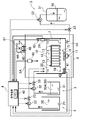
- FIG. 1 shows a schematic configuration diagram of a processing apparatus used in the processing method of the present invention.
- the processing apparatus of this figure includes a processing tank 1 filled with a non-conductive first fluid 20 that discharges the assembled battery 10 by immersion, and a fluid supply mechanism 2 that supplies the first fluid 20 to the processing tank 1.
- a conductive material supply mechanism 3 that supplies the conductive material 30 to the treatment tank 1, a fluid supply mechanism 2, and a control mechanism 4 that controls the conductive material supply mechanism 3.
- non-conductive means that the conductivity is substantially zero. For example, energization occurs between the positive and negative electrodes of the battery pack (typically, between the highest and lowest electrodes). Therefore, it means the conductivity in a range to the extent that no troubles due to electrolysis occur.
- the treatment tank 1 has an internal volume capable of completely immersing the assembled battery 10 to be treated in the filled first fluid 20, and a stirring device 15 for the first fluid 20 is provided at the bottom.
- the treatment tank 1 in this figure is provided with a porous bottom plate 18 at the bottom, and provided with stirring blades 16 of the stirring device 15 below the bottom plate 18.
- the stirring device 15 rotates the stirring blade 16 with a motor 17 to stir the internal first fluid 20.
- the treatment tank 1 is provided with a discharge part 1A for discharging the first fluid 20 at the bottom, and a discharge valve 53 is connected to the discharge part 1A.
- the fluid supply mechanism 2 supplies a non-conductive first fluid 20 in which the assembled battery 10 is immersed in the treatment tank 1.
- the first fluid 20 is preferably water. It is cheap and stable.
- the first fluid is a liquid or gas other than water, and an assembled battery is arranged without adding a conductive material, and the discharge current of the assembled battery is 1 C or less, preferably 0.1 C or less,
- a fluid that hardly conducts a discharge current that is, a fluid with low conductivity is used.
- a non-conductive liquid or gas having an electrical resistivity ( ⁇ ⁇ cm) of 5000 ⁇ ⁇ cm or more can be used.
- non-conductive liquid methyl ethyl ketone, acetone, ethanol, methanol, isopropyl alcohol, a fluorine-based inert liquid (Fluorinert [registered trademark]), or the like can be used.
- fluorine-based inert liquid Fluorinert [registered trademark]
- nitrogen gas, air, etc. can be used for nonelectroconductive gas.
- the processing apparatus of FIG. 1 uses water as the non-conductive first fluid 20.
- the fluid supply mechanism 2 of the processing apparatus of FIG. 1 includes a water tank 21 that stores tap water, a water pump 22 that sucks the tap water stored in the water tank 21 and supplies the tap water to the processing tank 1, and the water pump 22. And a water supply valve 23 connected to the output side.
- the fluid supply mechanism 2 supplies the tap water to the treatment tank 1 by opening the water supply valve 23 while operating the water pump 22.
- the fluid supply mechanism 2 shown in the figure includes a level sensor 24 that detects the liquid level of the processing tank 1.
- the control mechanism 4 detects the liquid level by the level sensor 24 and controls the operation of the water pump 22 and the opening / closing of the water supply valve 23.
- the level sensor 24 detects that water has been supplied to a predetermined liquid level while the first fluid 20 is being supplied to the treatment tank 1, the operation of the water pump 22 is stopped and water supply is performed.
- the valve 23 is closed.
- the control mechanism 4 is not necessarily provided with the level sensor 24.
- the water pump 22 has been operated for a preset time, it is stopped and water is supplied to the treatment tank 1 to a predetermined liquid level. it can.
- the fluid supply mechanism 2 in FIG. 1 supplies the tap water in the water tank 21 to the treatment tank 1 with the water pump 22, but without providing the water tank and the water pump, a water supply valve is connected to the tap water pipe, Tap water can also be supplied to the treatment tank from the water supply valve.
- the conductive material supply mechanism 3 adds the conductive material 30 to the water in the treatment tank 1 in which the assembled battery 10 is immersed, thereby increasing the conductivity. Thereby, the electrical conductivity of the first fluid can be improved.
- the conductive material 30 is salt water of a conductive liquid 30A in which sodium chloride is dissolved in water.
- the method of using salt water as the conductive liquid 30A can make the conductive material 30 inexpensive and can discharge the assembled battery 10 safely.
- the treatment method of the present invention does not specify the conductive liquid as salt water.
- the conductive liquid for example, all liquids having an electrical resistivity of, for example, 2000 ⁇ ⁇ cm or less, preferably 1000 ⁇ ⁇ cm or less, more preferably 500 ⁇ ⁇ cm or less, such as an aqueous sodium hydrogen carbonate solution, an LLC solution or a diluted solution An LLC solution, an ionic liquid, or the like can also be used.
- the processing method of the present invention does not specify the conductive substance as a conductive liquid that is a liquid.
- the conductive material is added to the first fluid of the non-conductive liquid, for example, a material that can increase the conductivity of the first fluid so that the assembled battery can be forcibly discharged when added to the first fluid. It is also possible to use a mist-like or powdery fluid that is sprayed on the first fluid that is dissolved or melted, or a non-conductive gas.
- an electrolyte solid or powder such as sodium chloride or sodium hydroxide can be used.
- the mist-like or powder-like fluid sprayed on the first fluid that is a non-conductive gas the mist obtained by spraying the above-described conductive liquid or the fine metal powder is sprayed in the form of powder.
- a fluid in which a fine metal powder and a mist of a conductive liquid are mixed can be used.
- the conductive liquid 30A which is the conductive material 30, is used as salt water.
- the conductive material supply mechanism 3 includes a conductive liquid tank 31 that stores a conductive liquid 30A, a conductive liquid pump 32 that supplies the conductive liquid 30A of the conductive liquid tank 31 to the processing tank 1, and a discharge of the conductive liquid pump 32. And a supply valve 33 for the conductive liquid 30A connected to the side. The operation of the conductive liquid pump 32 and the opening and closing of the supply valve 33 are controlled by the control mechanism 4 to add the conductive material 30 to the first fluid 20 in the processing tank 1.
- the conductive liquid tank 31 stores salt water having a sodium chloride concentration of 3% by weight.
- the electrical resistivity of this salt water is about 30 ⁇ ⁇ cm.
- salt water having an electrical resistivity of 20 ⁇ ⁇ cm or more and 100 ⁇ ⁇ cm or less can be stored and added to the first fluid 20 of the treatment tank 1. If the electrical resistivity of the brine in the conductive liquid tank 31 is too small, in other words, if the electrical conductivity is too high, the amount of salt water added to the treatment tank 1 is reduced and diffusion takes time and is stored in the treatment tank 1. The conductivity of water may increase locally.
- the salt water in the conductive liquid tank 31 is set in the above-described range so that it can be quickly diffused into the first fluid 20 of the treatment tank 1 and can be quickly made to have a predetermined conductivity.
- the conductive liquid pump 32 is a constant flow pump such as a diaphragm pump. Since the constant flow pump can control the operation time and control the supply amount of salt water to a set value, the conductivity of the treatment tank 1 can be accurately controlled without detecting the sodium chloride concentration in the treatment tank 1. However, it is not always necessary to use a constant flow pump for the conductive liquid pump. This is because a pump that is not a constant flow pump can control the supply amount by operating time.
- the control mechanism 4 controls the fluid supply mechanism 2 and the conductive material supply mechanism 3 in the following steps to supply the first fluid 20 and the conductive material 30 to the treatment tank 1.
- the fluid supply mechanism 2 is controlled to supply water in a volume that immerses the assembled battery 10 in the treatment tank 1.
- the fluid supply mechanism 2 can supply water to the processing tank 1 in which the assembled battery 10 to be discharged is set, or can supply a predetermined amount of water to the processing tank 1 before setting the assembled battery 10.
- the assembled battery 10 set in the treatment tank 1 has a plurality of secondary batteries 11 housed in an outer case 12 and an output terminal 13 provided outside, or a wire harness (not shown) connected to the output terminal 13. Connected.
- control mechanism 4 opens the water supply valve 23 and operates the water pump 22 to supply tap water from the water tank 21 to the treatment tank 1.
- the control mechanism 4 detects the level of water with the level sensor 24, and when the amount of water for immersing the assembled battery 10 in the treatment tank 1 is supplied, the operation of the water pump 22 is stopped and the water supply valve 23 is closed.
- the control mechanism 4 controls the conductive material supply mechanism 3 to supply the conductive material 30 to the treatment tank 1.
- the control mechanism 4 rotates the stirring blade 16 with the motor 17 to bring the first fluid 20 in the processing tank 1 into a stirring state.
- the control mechanism 4 operates the conductive liquid pump 32 with the supply valve 33 opened, and supplies the brine in the conductive liquid tank 31 to the treatment tank 1.
- the control mechanism 4 controls the amount of salt water supplied by the operation time of the conductive liquid pump 32 to control the conductivity of the treatment tank 1 to a set value.
- control mechanism 4 controls the operation time of the conductive liquid pump 32 so as to supply 1/10 salt water (salt concentration of 3% by weight) of the amount of water in the treatment tank 1, thereby chlorinating water in the treatment tank 1.
- the sodium concentration is 0.3% by weight.
- the control mechanism 4 stores the amount of the conductive liquid 30 ⁇ / b> A added to the treatment tank 1 and the addition time in the memory 40, and the salt water of the conductive liquid 30 ⁇ / b> A is stored in the treatment tank 1 so as to be stored in the memory 40. Added.
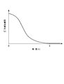
- the battery pack 10 when the battery pack 10 is discharged by adding salt water to the tap water in a state where the tap water is put in the treatment tank 1 and the battery pack 10 is immersed, the battery pack 10 is discharged. Electricity is discharged to conductive water adjusted to be high, and the voltage decreases with time. This state is shown in the graph of FIG.
- the battery pack 10 having an output voltage of several hundred volts drops in voltage due to the characteristics shown in this figure, and the output voltage is almost completely discharged to 1 V or less in about 5 hours.
- salt water is added to tap water to increase the conductivity of the water, and the assembled battery is discharged.
- the salt water is divided into a plurality of times every predetermined time in the water in which the assembled battery is immersed. It is also possible to discharge the assembled battery by gradually increasing the conductivity of water.
- the conductive liquid pump 32 is controlled by the control mechanism 4 to supply 1/10 salt water of the amount of water in the processing tank 1 so that the sodium chloride concentration of the water in the processing tank 1 is 0.3% by weight.
- the battery pack 10 is discharged by increasing the electrical conductivity of water in the treatment tank 1 to 0.9% by weight. In this method, as the battery pack 10 is discharged and the remaining capacity is reduced, the voltage is lowered, or the internal resistance is increased, the conductivity of water can be increased and the decrease in the discharge current can be reduced. 10 can be discharged more quickly.
- the method of gradually increasing the conductivity of the first fluid 20 in the treatment tank 1 can quickly and safely completely discharge the high-voltage assembled battery 10.
- the method of gradually increasing the conductivity of the first fluid 20 in the treatment tank 1 is to increase the conductivity stepwise by adding the conductive material 30 every predetermined time, as in the above treatment method, or It is also possible to continuously increase the conductivity by adding the conductive material 30 to the water in the treatment tank 1 continuously.
- the method of continuously adding the conductive material 30 gradually increases the conductivity of the water in the treatment tank 1 by controlling the flow rate of the salt water added to the water in the treatment tank 1 per unit time, that is, the flow rate of the conductive liquid 30A.
- the treatment method of the present invention does not necessarily increase the conductivity of the first fluid 20 in the treatment tank 1 as described above, but increases the conductivity by adding a conductive material to the treatment tank at a time. It can also be discharged.
- control mechanism 4 controls the addition amount of the conductive material 30 added to the first fluid 20 of the processing tank 1, that is, the conductivity of the fluid of the processing tank 1 by the output voltage of the assembled battery 10,
- the high-voltage assembled battery 10 can be discharged more safely and quickly.
- the control mechanism 4 stores in the memory 40 the characteristics for controlling the electrical conductivity of the fluid in the processing tank 1 with respect to the output voltage of the assembled battery 10, that is, the amount and time for adding the conductive material 30 to the processing tank 1. is doing.
- the control mechanism 4 controls the assembled battery 10 having a high output voltage so that the increase in the conductivity of the first fluid 20 in the treatment tank 1 is gradually increased, that is, the addition amount of the conductive material 30 is reduced. Then, the assembled battery 10 is discharged safely. However, in a state where the battery pack 10 is discharged and the voltage drops, the amount of the conductive material 30 added is increased and the battery is discharged quickly.
- control mechanism 4 controls the amount of the conductive material 30 added to the first fluid 20 of the processing tank 1, that is, the conductivity of the fluid of the processing tank 1 by the rated capacity (Ah) of the assembled battery 10.
- the control mechanism 4 stores the characteristics for controlling the electrical conductivity of the fluid in the processing tank 1 with respect to the rated capacity (Ah) of the assembled battery 10, that is, the amount and time for adding the conductive material 30 to the processing tank 1. 40.
- the control mechanism 4 controls the assembled battery 10 having a large rated capacity (Ah) so as to increase the rate of increasing the conductivity of the first fluid 20 in the treatment tank 1, that is, the addition of the conductive material 30.
- the battery pack 10 having a large rated capacity (Ah) is quickly discharged by increasing the amount.
- control mechanism 4 can detect the conductivity of the first fluid 20 in which the assembled battery 10 is immersed, that is, the conductivity of the fluid in the treatment tank 1 to control the amount of the conductive material 30 added. .
- the control mechanism 4 stores the addition amount of the conductive material 30 and the conductivity of the first fluid with respect to time in the memory 40. As the time passes, the processing tank 1 is stored in the memory 40. Control the electrical conductivity of the fluid.
- control mechanism 4 can include a conductivity sensor 41 that detects the conductivity of the fluid in the processing tank 1.
- the control mechanism 4 controls the conductive material supply mechanism 3 to adjust the amount of addition of the conductive material 30 while detecting the conductivity of the first fluid 20 formed by immersing the assembled battery 10 with the conductivity sensor 41. Then, the conductivity of the first fluid 20 in which the assembled battery 10 is immersed is controlled.
- the processing tank 1 of FIG. 1 includes a conductivity sensor 41 that detects the conductivity of the first fluid 20 to which the conductive material 30 is added.
- the conductivity sensor 41 detects the conductivity specified from the battery resistance of the first fluid 20 to which the conductive material 30 is added and outputs the detected conductivity to the control mechanism 4.
- the control mechanism 4 accurately controls the conductivity of the fluid to which the conductive material 30 is added by controlling the conductive material supply mechanism 3 so that the conductivity detected by the conductivity sensor 41 becomes a predetermined value. Can do.
- the conductivity sensor is not necessarily limited to a sensor that specifies the conductivity from the electrical resistance of the fluid to which the conductive material 30 is added.
- the conductivity of the fluid can be specified from the salt water concentration of the fluid to which the salt water is added. Therefore, a concentration sensor that detects the salt water concentration of the fluid can also be used as the conductivity sensor.
- control mechanism 4 shown in FIG. 1 also includes a water temperature sensor 42 that detects the temperature of the fluid in the processing tank 1.
- the water temperature sensor 42 detects the water temperature of the fluid in the processing tank 1 and outputs it to the control mechanism 4.
- this processing apparatus can quickly detect this via the water temperature sensor 42, thereby improving safety.
- the above processing apparatus controls the conductive material supply mechanism 3 with the control mechanism 4 to add the conductive material 30 of the conductive liquid 30 ⁇ / b> A to the processing tank 1.
- the treatment method of the present invention does not necessarily require the conductive material to be a conductive liquid, and the conductive material is a conductive solid that is dissolved in the first fluid to increase the conductivity of the first fluid. Can do.
- the conductive solid is, for example, a tablet obtained by compression-molding sodium chloride or molding it into a solid with a binder.
- the number of conductive solids supplied to the water in the treatment tank 1 can control the conductivity of water.
- the conductive solid can be automatically supplied, but the user can put it into the treatment tank 1 to adjust the conductivity.
- the method of supplying the conductive solid to the water in the processing tank 1 is that the first solid 20 in the processing tank 1 is obtained by dissolving the conductive solid supplied to the processing tank 1 over time. The conductivity can be gradually increased.
- powdered sodium chloride can also be used for the conductive material 30.
- the conductive material 30 adds a predetermined weight of sodium chloride powder to the water in the treatment tank 1 in which the assembled battery 10 is immersed, and controls the conductivity of the water to discharge the assembled battery 10.
- the method of adding powdered sodium chloride to the water in the treatment tank 1 can be dissolved in water in a short time compared to the conductive solid, the first fluid 20 in the treatment tank 1 is used. The conductivity can be increased quickly.
- the fluid to which the conductive material 30 is added may be electrolyzed by the discharge of the assembled battery 10 to generate hydrogen gas.
- the processing apparatus shown in the figure includes a hydrogen concentration sensor 43 that detects the hydrogen gas concentration inside the processing chamber 9 in order to prevent such a situation.
- the hydrogen concentration sensor 43 detects the hydrogen concentration inside the processing chamber 9 and outputs it to the control mechanism 4.
- the control mechanism 4 notifies this to the outside by means of an alarm, a lamp or the like.
- the processing apparatus shown in the figure is provided with a ventilator 45 at the top of the processing chamber 9 in order to ventilate the inside of the processing chamber 9.
- the processing chamber 9 shown in the figure is provided with a duct 44 that is partially opened at the top surface 9 ⁇ / b> A and connected to the outside, and a ventilation device 45 is disposed in the duct 44.
- the illustrated ventilator 45 includes a fan 46 that forcibly blows gas inside the processing chamber 9 to the outside, and a motor 47 that rotates the fan 46. The operation of the motor 47 is controlled by the control mechanism 4.
- the ventilator 45 starts operation when the hydrogen concentration in the processing chamber 9 becomes higher than a predetermined concentration, exhausts the hydrogen gas in the processing chamber 9 to the outside, and the processing chamber 9 is filled with hydrogen gas.
- the ventilation mechanism can be operated during the process of discharging the assembled battery 10 without necessarily operating only when the hydrogen concentration is high.
- gas other than hydrogen gas may be generated due to electrolysis or the like. Therefore, by operating the ventilation device 45 during the discharge process of the assembled battery 10, these gases can be exhausted to the outside of the processing chamber 9 to improve the environment inside the processing chamber 9.
- the processing apparatus shown in the figure has a monitoring camera 48 disposed above the processing tank 1 so that the processing state of the assembled battery 10 immersed in the processing tank 1 can be observed from the outside.
- a CCD camera is arranged as a monitoring camera 48 on the top surface 9 ⁇ / b> A of the treatment room 9.
- the assembled battery 10 to be processed in the processing tank 1 can be monitored by the monitoring camera 48 arranged in the processing chamber 9, so that the user can transmit from the monitoring camera 48 without monitoring inside the processing chamber 9.
- the video can be monitored with a monitor in a separate room and processed safely.
- the fluid in the processing tank 1 is discharged to the outside by opening the discharge valve 53 connected to the bottom of the processing tank 1.
- the fluid after the discharge treatment contains a substance generated by a chemical reaction such as electrolysis in a solid or liquid state, or contains a generated gas dissolved in the fluid. Therefore, the fluid after the discharge process is collected in the waste liquid tank 51 and then subjected to the waste liquid treatment.
- the processing apparatus shown in the figure includes a waste liquid mechanism 5 on the discharge side of the processing tank 1 in order to discard the processed fluid in the processing tank 1.
- the illustrated waste liquid mechanism 5 includes a waste liquid tank 51 that stores the waste liquid 50 discharged from the processing tank 1, and a waste liquid pump 52 that supplies the waste liquid 50 discharged from the processing tank 1 to the waste liquid tank 1.
- the waste liquid mechanism 5 supplies the waste liquid tank 51 by operating the waste liquid pump 52 in a state where the discharge valve 53 is opened and the fluid in the treatment tank 1 is discharged.
- the waste liquid 50 collected in the waste liquid tank 51 is subjected to a predetermined disposal process.
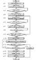
- the assembled battery processing method described above is the flowchart shown in FIG. 3 and discharges the assembled battery as follows.
- the processing method shown below shows an example in which the first fluid is tap water and the conductive substance is salt water which is a conductive liquid.
- the flowchart of FIG. 3 shows an example in which salt water is added every predetermined time to increase the conductivity of tap water, which is the first fluid, stepwise.
- the control mechanism 4 controls the fluid supply mechanism 2 to supply water to the processing tank 1.
- the control mechanism 4 opens the water supply valve 23, operates the water pump 22, and supplies tap water from the water tank 21 to the treatment tank 1.
- the control mechanism 4 detects the liquid level of the water with the level sensor 24, and loops this step until the treatment tank 1 is supplied with an amount of water that immerses the assembled battery 10.
- the control mechanism 4 stops the operation of the water pump 22 and closes the water supply valve 23.
- the control mechanism 4 controls the conductive material supply mechanism 3 to supply the treatment tank 1 with salt water that is the conductive liquid 30A.
- the control mechanism 4 operates the conductive liquid pump 32 with the supply valve 33 opened, and supplies the brine in the conductive liquid tank 31 to the processing tank 1.
- the control mechanism 4 controls the amount of salt water supplied by the operation time of the conductive liquid pump 32 to control the conductivity of the treatment tank 1 to a set value.
- the control mechanism 4 counts the operation time of the conductive liquid pump 32 with a timer (not shown), and supplies a predetermined amount of salt water to the treatment tank 1.
- the control mechanism 4 stops the operation of the conductive liquid pump 32 and closes the supply valve 33.
- the control mechanism 4 controls the waste liquid mechanism 5 to discharge the fluid in the processing tank 1.
- the control mechanism 4 opens the discharge valve 53, operates the discharge pump 52 to discharge the fluid from the processing tank 1, and collects the discharged fluid as the waste liquid 50 in the waste liquid tank 51.
- a non-conductive first fluid that immerses an assembled battery disposed in a treatment tank is used as a gas, and a conductive material added to the non-conductive first fluid that is a gas is added.
- a mist-like or powdery fluid having conductivity can be obtained.
- the inside of a sealed processing tank is filled with nitrogen gas or air as a non-conductive first fluid, and an assembled battery is disposed in the gas and added to the first fluid.
- a conductive solution of salt water is sprayed in a mist form from the nozzle to discharge the assembled battery in the treatment tank.
- the assembled battery is discharged using a fine mist of a conductive liquid floating in the processing tank as a medium.
- the fluid to be added to the first fluid is a fine metal powder, for example, a powder body made of a fine powder of aluminum, and the powder body is sprayed into a processing tank to perform processing.
- the assembled battery can also be discharged using a fluid of fine metal powder floating in the tank as a medium.
- the fluid added to the first fluid is a fluid in which fine metal powder particles and a mist of conductive liquid are mixed, and these mixed fluids are sprayed into a processing tank to form an assembled battery. Can also be discharged.
- the battery pack processing method of the present invention can safely and quickly discharge a battery pack having a high output by laminating a large number of secondary batteries, so that the battery for driving an electric vehicle, natural energy, It is suitably used as a method for processing a battery for storing midnight power.
Landscapes
- Engineering & Computer Science (AREA)
- Manufacturing & Machinery (AREA)
- Chemical & Material Sciences (AREA)
- Chemical Kinetics & Catalysis (AREA)
- Electrochemistry (AREA)
- General Chemical & Material Sciences (AREA)
- Secondary Cells (AREA)
- Battery Electrode And Active Subsutance (AREA)
Abstract
複数の二次電池を直列に接続している組電池を、安全に、しかも速やかに放電させて出力電圧を低下させる。 組電池の処理方法は、複数の二次電池(11)を直列に接続してなる組電池(10)を放電させる処理方法であって、組電池(10)を非導電性の第1の流体(20)中に配置した後、第1の流体(20)の導電性を向上させる導電物質(30)を第1の流体(20)に添加する。
Description
本発明は、複数の二次電池を直列に接続して出力電圧を高くしている組電池の処理方法に関し、とくに、ハイブリッドカーや電気自動車の走行用バッテリのように高電圧な組電池を安全に処理するのに最適な組電池の処理方法に関する。
複数の二次電池を直列に接続している組電池は、二次電池を直列に接続している個数に比例して出力電圧が高くなるので、これを安全に廃棄するためには、二次電池を放電して出力電圧を低くすることが大切である。廃棄される組電池を放電するために、塩水などの導電性の液体に浸漬して強制的に放電する処理方法が開発されている。(特許文献1参照)
従来の処理方法は、使用済みのリチウム電池を多数個ポリプロピレン製の篭に入れて、イオン導電性の液体である食塩水を入れた浴中に浸漬して、電池の残存電力を放電させる。また、使用済み電池を、コンベアによって順次搬送しながら自動的に導電性を有する液体に浸漬する。
以上の処理方法は、ひとつの電池を食塩水に浸漬して簡単に放電できる。しかしながら、複数の二次電池を直列に接続している組電池を食塩水に浸漬すると、極めて大きな放電電流が流れて発火する等の弊害がある。放電電流が組電池の出力電圧に比例して大きくなるからである。組電池の放電電流は、浸漬する食塩水の導電率を低くして、すなわち塩分濃度を低くして小さくできるが、放電電流を小さくすると、組電池を完全に放電して出力電圧を低下するのに極めて長い時間がかかる欠点がある。
本発明は、以上の欠点を解決することを目的に開発されたものである。本発明の重要な目的は、複数の二次電池を直列に接続している組電池を、安全に、しかも速やかに放電させて出力電圧を低下できる組電池の処理方法を提供することにある。
本発明の組電池の処理方法は、複数の二次電池11を直列に接続してなる組電池10を放電させる処理方法であって、組電池10を非導電性の第1の流体20中に配置した後、第1の流体20の導電性を向上させる導電物質30を第1の流体20に添加する。
なお、本明細書において、「非導電性の第1の流体」とは、組電池を浸漬した状態で、組電池の放電電流を1C以下とする導電性の低い流体を意味するものとする。
なお、本明細書において、「非導電性の第1の流体」とは、組電池を浸漬した状態で、組電池の放電電流を1C以下とする導電性の低い流体を意味するものとする。
以上の処理方法は、複数の二次電池を直列に接続している組電池を、安全に、しかも速やかに放電させて出力電圧を低下できる特徴がある。それは、組電池を非導電性の第1の流体に浸漬して、組電池を浸漬している第1の流体に導電物質を添加して第1の流体の導電率を向上して、導電率で組電池の放電電流をコントロールしながら組電池を強制的に放電できるからである。とくに、以上の処理方法は、導電物質の添加量をコントロールして第1の流体の導電率を調整できるので、出力電圧の高い組電池にあっては、導電物質の添加量を少なくして放電電流を小さくし、また出力電圧の低い組電池にあっては、導電物質の添加量を多くして、放電電流を最適値にコントロールして、組電池を速やかに放電できる。さらに、以上の処理方法は、組電池を第1の流体に浸漬する状態で、第1の流体の導電率をコントロールして放電させるので、組電池の出力端子等の高電圧部分を第1の流体に浸漬した状態で、第1の流体の導電率をコントロールして放電できる。このため、高電圧部分が導電率の高い第1の流体に接触して過大な電流が流れたり、あるいは発火するのを確実に防止しながら、出力電圧の高い組電池をも安全に放電できる。また、組電池を浸漬する状態で第1の流体の導電率をコントロールするので、組電池の出力電圧が低くなる状態では、さらに導電物質を添加して、より速やかに組電池を完全に放電できる。
本発明の組電池の処理方法は、組電池10を浸漬している第1の流体20の導電率を次第に高くするように、導電物質30を添加することができる。
以上の処理方法は、第1の流体に浸漬された組電池が放電されて出力電圧が低下する状態で、添加される導電物質によって第1の流体の導電率を高くして、より速やかに組電池を放電できる。
以上の処理方法は、第1の流体に浸漬された組電池が放電されて出力電圧が低下する状態で、添加される導電物質によって第1の流体の導電率を高くして、より速やかに組電池を放電できる。
本発明の組電池の処理方法は、組電池10を浸漬している第1の流体20に連続的に導電物質30を添加して、導電性第1の流体の導電率を連続的に高くすることができる。
この処理方法は、組電池を浸漬している第1の流体の導電率を連続的に次第に高くするので、放電されて次第に電圧が低下する組電池の放電電流が減少するのを少なくして、組電池をより速やかに放電できる。
この処理方法は、組電池を浸漬している第1の流体の導電率を連続的に次第に高くするので、放電されて次第に電圧が低下する組電池の放電電流が減少するのを少なくして、組電池をより速やかに放電できる。
本発明の組電池の処理方法は、組電池10を浸漬している第1の流体20に、所定の時間経過すると所定量の導電物質30を添加して、第1の流体20の導電率を段階的に高くすることができる。
この処理方法は、組電池を浸漬している第1の流体の導電率を段階的に高くするので、放電されて次第に電圧が低下する組電池の放電電流が減少するのを少なくして、組電池をより速やかに放電できる。
この処理方法は、組電池を浸漬している第1の流体の導電率を段階的に高くするので、放電されて次第に電圧が低下する組電池の放電電流が減少するのを少なくして、組電池をより速やかに放電できる。
本発明の組電池の処理方法は、第1の流体20に水を使用し、導電物質30に塩化ナトリウムを使用することができる。
以上の処理方法は、導電物質に安価な塩化ナトリウムを使用するので、処理コストを低減しながら、少量の導電物質を添加して、組電池を速やかに放電できる特徴がある。
以上の処理方法は、導電物質に安価な塩化ナトリウムを使用するので、処理コストを低減しながら、少量の導電物質を添加して、組電池を速やかに放電できる特徴がある。
本発明の組電池の処理方法は、組電池10を浸漬してなる第1の流体20を攪拌して、組電池10を放電することができる。
以上の処理方法は、組電池を浸漬する第1の流体の導電率を均一にしながら、より安全に組電池を放電できる。それは、組電池の出力端子の近傍の導電率が局部的に高くなって、放電電流が過大になる弊害を防止できるからである。
以上の処理方法は、組電池を浸漬する第1の流体の導電率を均一にしながら、より安全に組電池を放電できる。それは、組電池の出力端子の近傍の導電率が局部的に高くなって、放電電流が過大になる弊害を防止できるからである。
本発明の組電池の処理方法は、組電池10を浸漬してなる第1の流体20に添加する導電物質30の添加量を、組電池10の出力電圧でコントロールすることができる。
以上の処理方法は、低電圧から高電圧までのあらゆる組電池を安全に、しかも速やかに放電できる特徴がある。それは、出力電圧の高い組電池を浸漬する第1の流体には、導電物質の添加量を少なくして、過大な電流で放電される弊害を防止し、また、低電圧の組電池を浸漬する第1の流体には、導電物質の添加量を多くして、速やかに放電できるからである。
以上の処理方法は、低電圧から高電圧までのあらゆる組電池を安全に、しかも速やかに放電できる特徴がある。それは、出力電圧の高い組電池を浸漬する第1の流体には、導電物質の添加量を少なくして、過大な電流で放電される弊害を防止し、また、低電圧の組電池を浸漬する第1の流体には、導電物質の添加量を多くして、速やかに放電できるからである。
本発明の組電池の処理方法は、組電池10を浸漬してなる第1の流体20に添加する導電物質30の添加量を、組電池10の定格容量(Ah)でコントロールすることができる。
以上の処理方法は、小容量の組電池から大容量の組電池までを、速やかに放電できる特徴がある。それは、小容量の組電池には放電電流を小さくして安全に放電し、大容量の組電池は放電電流を大きくして放電できるからである。
以上の処理方法は、小容量の組電池から大容量の組電池までを、速やかに放電できる特徴がある。それは、小容量の組電池には放電電流を小さくして安全に放電し、大容量の組電池は放電電流を大きくして放電できるからである。
本発明の組電池の処理方法は、組電池10を浸漬してなる第1の流体20の導電率を検出して、導電物質30の添加量をコントロールすることができる。
以上の処理方法は、導電物質の添加量を調整して、組電池を浸漬する第1の流体の導電率を理想的な値にコントロールして、組電池を理想的な放電電流で放電できる。
以上の処理方法は、導電物質の添加量を調整して、組電池を浸漬する第1の流体の導電率を理想的な値にコントロールして、組電池を理想的な放電電流で放電できる。
本発明の組電池の処理方法は、導電性を有する第1の流体である導電液30Aを導電物質30とし、この導電液30Aをポンプでもって組電池10を浸漬している第1の流体20に添加して第1の流体20の導電率をコントロールすることができる。
以上の処理方法は、塩水などの導電物質を簡単な添加装置で第1の流体に添加して、組電池を浸漬する第1の流体の導電率を好ましい状態にコントロールできる。
以上の処理方法は、塩水などの導電物質を簡単な添加装置で第1の流体に添加して、組電池を浸漬する第1の流体の導電率を好ましい状態にコントロールできる。
本発明の組電池の処理方法は、導電物質30を、第1の流体に溶解されて第1の流体の導電率を高くする導電性固形物として、この導電性固形物を、組電池10を浸漬してなる第1の流体20に添加して、第1の流体20の導電率をコントロールすることができる。
以上の処理方法は、導電性固形物を第1の流体に供給する個数や量で、組電池を浸漬している第1の流体の導電率を最適値にコントロールして、組電池を放電できる。
以上の処理方法は、導電性固形物を第1の流体に供給する個数や量で、組電池を浸漬している第1の流体の導電率を最適値にコントロールして、組電池を放電できる。
本発明の組電池の処理方法は、組電池10を、複数の二次電池11を外装ケース12に収納して出力端子13を外部に設けてなる組電池10とすることができる。
以上の処理方法は、二次電池を外装ケースに収納している組電池をも理想的な状態で放電できる。二次電池を外装ケースに収納して外部に出力端子を露出してなる組電池は、出力端子が導電液に接触する瞬間に、出力端子間に大電流が流れて発火する等の弊害がある。ところが、以上の処理方法は、組電池を第1の流体に浸漬する状態で、第1の流体の導電率を高くするので、出力端子が第1の流体中に浸漬される状態で、第1の流体に導電物質が添加されて導電率が次第に高くなる。このため、出力端子が直接に導電率の高い第1の流体に接触することがなく、出力端子を第1の流体に浸漬する状態で第1の流体の導電率を高くして安全に放電できる。
以上の処理方法は、二次電池を外装ケースに収納している組電池をも理想的な状態で放電できる。二次電池を外装ケースに収納して外部に出力端子を露出してなる組電池は、出力端子が導電液に接触する瞬間に、出力端子間に大電流が流れて発火する等の弊害がある。ところが、以上の処理方法は、組電池を第1の流体に浸漬する状態で、第1の流体の導電率を高くするので、出力端子が第1の流体中に浸漬される状態で、第1の流体に導電物質が添加されて導電率が次第に高くなる。このため、出力端子が直接に導電率の高い第1の流体に接触することがなく、出力端子を第1の流体に浸漬する状態で第1の流体の導電率を高くして安全に放電できる。
本発明の組電池の処理方法は、組電池10を、電動車両を走行させる走行用バッテリとすることができる。
以上の処理方法は、走行用バッテリのように高電圧の組電池を安全に放電できる。
以上の処理方法は、走行用バッテリのように高電圧の組電池を安全に放電できる。
以下、本発明の実施の形態を図面に基づいて説明する。ただし、以下に示す実施の形態は、本発明の技術思想を具体化するための組電池の処理方法を例示するものであって、本発明は処理方法を以下の方法には特定しない。さらに、この明細書は、特許請求の範囲に示される部材を、実施の形態の部材に特定するものでは決してない。
本発明の組電池の処理方法は、複数の二次電池を直列に接続して、出力電圧を高くしている組電池の放電処理に最適である。この種の組電池として、たとえば、ハイブリッドカーや電気自動車などの電動車両を走行させるモータに電力を供給する走行用バッテリ、太陽電池パネルや風力発電などの自然エネルギー、あるいは深夜電力など蓄電する蓄電用バッテリがある。これ等の組電池は、多数の二次電池を直列に接続して出力電圧を高くし、かつ蓄電容量を大きくしている。これ等の組電池は、充放電を繰り返して劣化し、蓄電できる容量が小さくなると廃棄される。また、車両に搭載される組電池においては、車両事故等により、走行用バッテリが破損して使用できなくなると廃棄される。とくに、走行用バッテリの破損状態によっては、走行用バッテリを解体して分解することなく廃棄されることがある。ただ、これらの組電池は、廃棄される状態で、常に完全に放電された状態とは限らない。完全に放電されない組電池は、出力端子やこれに接続しているワイヤーハーネスなどに高電圧が印加されている。したがって、組電池を強制的に放電して、出力電圧を低く、好ましくは0Vまで低下させて完全に放電される状態として安全に廃棄できる。本発明の処理方法は、組電池を強制的に放電させる方法である。
図1は、本発明の処理方法に使用する処理装置の概略構成図を示している。この図の処理装置は、組電池10を浸漬して放電させる非導電性の第1の流体20を充填する処理槽1と、この処理槽1に第1の流体20を供給する流体供給機構2と、処理槽1に導電物質30を供給する導電物質供給機構3と、流体供給機構2と導電物質供給機構3を制御する制御機構4とを備えている。なお、ここで言う非導電性の意味は、導電率が略ゼロであることを示し、例えば組電池の正負の電極間(典型的には最高位と最低位の電極間)において通電が起こる事により、電気分解等による不具合が発生しない程度までの範囲の導電性のことをいう。
処理槽1は、充填している第1の流体20に処理される組電池10を完全に浸漬できる内容積を有し、底部には、第1の流体20の攪拌装置15を設けている。この図の処理槽1は、底部に多孔性の底板18を設けて、底板18の下方に攪拌装置15の攪拌羽根16を設けている。攪拌装置15は、攪拌羽根16をモータ17で回転して、内部の第1の流体20を攪拌する。さらに、処理槽1は、底部に第1の流体20を排出する排出部1Aを設けて、この排出部1Aに排出弁53を連結して設けている。
流体供給機構2は、処理槽1に組電池10を浸漬させる非導電性の第1の流体20を供給する。この第1の流体20には、好ましくは水を使用する。安価で安定しているからである。ただ、第1の流体には、水以外の液体や気体であって、導電物質を添加しない状態で組電池を配置して、組電池の放電電流を1C以下、好ましくは0.1C以下、さらに好ましくは殆ど放電電流を流さない流体、すなわち導電率の小さい流体を使用する。この第1の流体には、例えば、電気抵抗率(Ω・cm)を5000Ω・cm以上とする非導電液や気体が使用できる。非導電液には、メチルエチルケトン、アセトン、エタノール、メタノール、イソプロピルアルコール、フッ素系の不活性液体(フロリナート[登録商標])等が使用できる。また、非導電性の気体には、窒素ガスや空気などが使用できる。
以下、図1の処理装置は、非導電性の第1の流体20に水を使用する。したがって、図1の処理装置の流体供給機構2は、水道水を蓄える水タンク21と、この水タンク21に蓄える水道水を吸入して処理槽1に供給する水ポンプ22と、この水ポンプ22の出力側に連結している給水弁23とを備える。この流体供給機構2は、水ポンプ22を運転する状態で給水弁23を開いて、水道水を処理槽1に供給する。さらに、図の流体供給機構2は、処理槽1の液面レベルを検出するレベルセンサ24を備えている。制御機構4は、レベルセンサ24で液面レベルを検出して、水ポンプ22の運転と給水弁23の開閉を制御する。すなわち、処理槽1に第1の流体20を供給している状態で、レベルセンサ24が所定の液面レベルまで水が供給されたことを検出すると、水ポンプ22の運転を停止して、給水弁23を閉じる。制御機構4は、必ずしもレベルセンサ24を設けることなく、たとえば、水ポンプ22をあらかじめ設定している時間運転した後、停止して、処理槽1に所定の液面レベルまで水を供給することができる。図1の流体供給機構2は、水タンク21の水道水を水ポンプ22で処理槽1に供給するが、水タンクと水ポンプを設けることなく、水道水の配管に給水弁を連結して、給水弁から処理槽に水道水を供給することもできる。
導電物質供給機構3は、組電池10を浸漬している処理槽1の水に導電物質30を添加して、導電率を高くする。これにより、第1の流体の導電性を向上させることができる。図の導電物質供給機構3は、導電物質30を、水に塩化ナトリウムを溶解している導電液30Aの塩水とする。導電液30Aに塩水を使用する方法は、導電物質30を安価にでき、また、組電池10を安全に放電できる。だたし、本発明の処理方法は、導電液を塩水には特定しない。導電液には、たとえば、電気抵抗率を、たとえば2000Ω・cm以下、好ましくは1000Ω・cm以下、さらに好ましくは500Ω・cm以下とする全ての液体、たとえば、炭酸水素ナトリウム水溶液、LLC溶液や希釈したLLC溶液、イオン液体なども使用できる。
さらに、本発明の処理方法は、導電物質を、液体である導電液には特定しない。導電物質には、第1の流体に添加する状態で、組電池を強制的に放電できるように、第1の流体の導電率を大きくできる物質、例えば、非導電液の第1の流体に添加されて溶解される固体、あるいは非導電性の気体である第1の流体に噴霧される霧状や粉粒状の流体等とすることもできる。非導電液の第1の流体に溶解されて第1の流体の導電率を高くする固体の導電物質には、塩化ナトリウムや水酸化ナトリウム等の電解質の固形や粉末が使用できる。また、非導電性の気体である第1の流体に噴霧される霧状や粉粒状の流体には、前述の導電液を霧状に噴霧したミストや、金属の微細な粉末を粉粒状に噴霧した流体、あるいは、微細な金属粉と導電液のミストを混合した流体等が使用できる。
図1の処理装置は、導電物質30である導電液30Aを塩水としている。この導電物質供給機構3は、導電液30Aを蓄えている導電液タンク31と、この導電液タンク31の導電液30Aを処理槽1に供給する導電液ポンプ32と、この導電液ポンプ32の排出側に連結している導電液30Aの供給弁33とを備えている。導電液ポンプ32の運転と供給弁33の開閉は、制御機構4にコントロールされて、処理槽1の第1の流体20に導電物質30を添加する。
導電液タンク31は、塩化ナトリウム濃度を3重量%とする塩水を蓄えている。この塩水の電気抵抗率は約30Ω・cmとなる。導電液タンク31には、たとえば、電気抵抗率を20Ω・cm以上であって、100Ω・cm以下とする塩水を蓄えて、処理槽1の第1の流体20に添加することができる。導電液タンク31の塩水は、電気抵抗率が小さすぎると、言い換えると導電率が大き過ぎると、処理槽1に添加する塩水量が少なくなって拡散に時間がかかって、処理槽1に蓄えられる水の導電率が局部的に大きくなることがある。局部的に導電率が高くなる塩水が、組電池10の出力端子のように高電圧が露出する部分などの近傍にあると、一時的に放電電流が大きくなる。反対に塩水の導電率が小さすぎると、処理槽1の第1の流体20への供給量が多くなって、導電率を速やかに設定値まで高くできなくなる。したがって、導電液タンク31の塩水は、処理槽1の第1の流体20に速やかに拡散でき、かつ速やかに所定の導電率にできるように、前述の範囲に設定される。
導電液ポンプ32は、ダイヤフラムポンプなどの定流量ポンプである。定流量ポンプは運転時間を制御して、塩水の供給量を設定値にコントロールできるので、処理槽1の塩化ナトリウム濃度を検出することなく、処理槽1の導電率を正確にコントロールできる。ただ、導電液ポンプには、必ずしも定流量ポンプを使用する必要はない。定流量ポンプでないポンプも、運転時間で供給量をコントロールできるからである。
制御機構4は、以下の工程で、流体供給機構2と導電物質供給機構3とをコントロールして、処理槽1に第1の流体20を供給し、また導電物質30を供給する。
(1)処理槽1に組電池10をセットする状態で、流体供給機構2を制御して、処理槽1に組電池10を浸漬する液量の水を供給する。流体供給機構2は、放電処理する組電池10をセットした処理槽1に水を供給し、あるいは組電池10をセットする前に処理槽1に所定量の水を供給することもできる。処理槽1にセットされる組電池10は、複数の二次電池11を外装ケース12に収納して出力端子13を外部に設けたもの、あるいは、出力端子13にワイヤーハーネス(図示せず)を接続したものである。
この工程において、制御機構4は、給水弁23を開いて水ポンプ22を運転して、水タンク21の水道水を処理槽1に供給する。制御機構4は、レベルセンサ24で水の液面レベルを検出し、処理槽1に組電池10を浸漬する水量が供給されると、水ポンプ22の運転を停止して給水弁23を閉じる。
(2)その後、制御機構4は、導電物質供給機構3を制御して、処理槽1に導電物質30を供給する。処理槽1に導電物質30を供給する状態で、制御機構4は攪拌羽根16をモータ17で回転して、処理槽1の第1の流体20を攪拌状態とする。この工程において、制御機構4は、供給弁33を開く状態で、導電液ポンプ32を運転して、導電液タンク31の塩水を処理槽1に供給する。制御機構4は、導電液ポンプ32の運転時間で塩水の供給量をコントロールして、処理槽1の導電率を設定値にコントロールする。たとえば、制御機構4は、処理槽1の水量の1/10の塩水(塩分濃度3重量%)を供給するように、導電液ポンプ32の運転時間を制御して、処理槽1の水の塩化ナトリウム濃度を0.3重量%とする。制御機構4は、処理槽1に添加する導電液30Aの量と、添加する時間とをメモリ40に記憶しており、このメモリ40に記憶するように、導電液30Aの塩水を処理槽1に添加する。
以上のように、処理槽1に水道水を入れて組電池10を浸漬する状態で、水道水に塩水を添加して水の導電率を高くして組電池10を放電すると、組電池10は導電率が高く調整された導電性の水に放電されて、時間と共に電圧が低下する。この状態を図2のグラフに示している。出力電圧を数百Vとする組電池10は、この図で示す特性で電圧が低下して、約5時間で出力電圧が1V以下とほぼ完全に放電される。
以上の方法は、水道水に塩水を添加して水の導電率を高くして組電池を放電するが、組電池を浸漬している水に、所定の時間毎に複数回に分けて塩水を供給して、水の導電率を次第に高くして組電池を放電することもできる。この方法は、たとえば、制御機構4で導電液ポンプ32を制御して、処理槽1の水量の1/10の塩水を供給して処理槽1の水の塩化ナトリウム濃度を0.3重量%とし、その後10分経過する毎に、同じ水量の塩水を3回添加して、処理槽1の水の塩化ナトリウム濃度を、0.3重量%から、0.5重量%、0.7重量%、0.9重量%と多くして、処理槽1の水の導電率を高くして組電池10を放電する。この方法は、組電池10が放電されて残容量が減少し、電圧が低下し、あるいは内部抵抗が増加するにしたがって、水の導電率を高くして放電電流の減少を少なくできるので、組電池10をより速やかに放電できる。
以上のように、処理槽1の第1の流体20の導電率を次第に高くする方法は、速やかに、しかも安全に高電圧の組電池10を完全に放電できる。処理槽1の第1の流体20の導電率を次第に高くする方法は、以上の処理方法のように、所定の時間毎に導電物質30を添加して、段階的に導電率を高くし、あるいは連続的に導電物質30を処理槽1の水に添加して、導電率を連続的に高くすることもできる。連続的に導電物質30を添加する方法は、処理槽1の水に単位時間に添加する塩水、すなわち導電液30Aの流量をコントロールして、処理槽1の水の導電率を次第に大きくする。ただ、本発明の処理方法は、必ずしも以上のように次第に処理槽1の第1の流体20の導電率を高くすることなく、処理槽に一度に導電物質を添加して導電率を高くして放電することもできる。
さらに、制御機構4は、処理槽1の第1の流体20に添加する導電物質30の添加量、すなわち、処理槽1の流体の導電率を、組電池10の出力電圧でコントロールすることで、高電圧の組電池10をより安全に、しかも速やかに放電できる。この制御機構4は、組電池10の出力電圧に対して、処理槽1の流体の導電率をコントロールする特性、すなわち、処理槽1に導電物質30を添加する量と時間とをメモリ40に記憶している。この制御機構4は、出力電圧の高い組電池10は、処理槽1の第1の流体20の導電率の上昇を緩やかに上昇させるように制御して、すなわち、導電物質30の添加量を少なくして、組電池10を安全に放電する。ただ、組電池10が放電されて電圧が低下する状態では、導電物質30の添加量を多くして、速やかに放電させる。
また、制御機構4は、処理槽1の第1の流体20に添加する導電物質30の添加量、すなわち、処理槽1の流体の導電率を、組電池10の定格容量(Ah)でコントロールして、定格容量(Ah)の大きい組電池10をより安全に、しかも速やかに放電できる。この制御機構4は、組電池10の定格容量(Ah)に対して、処理槽1の流体の導電率をコントロールする特性、すなわち、処理槽1に導電物質30を添加する量と時間とをメモリ40に記憶している。この制御機構4は、定格容量(Ah)の大きい組電池10は、処理槽1の第1の流体20の導電率を上昇させる割合を大きくするように制御して、すなわち、導電物質30の添加量を多くして、定格容量(Ah)の大きい組電池10を速やかに放電する。
さらに、制御機構4は、組電池10を浸漬している第1の流体20の導電率、すなわち処理槽1の流体の導電率を検出して、導電物質30の添加量をコントロールすることもできる。この制御機構4は、導電物質30の添加量と時間に対する第1の流体の導電率をメモリ40に記憶しており、メモリ40に記憶されるように、時間が経過するにしたがって、処理槽1の流体の導電率をコントロールする。
さらに、制御機構4は、処理槽1の流体の導電率を検出する導電率センサ41を備えることができる。この制御機構4は、組電池10を浸漬してなる第1の流体20の導電率を導電率センサ41で検出しながら、導電物質供給機構3を制御して導電物質30の添加量を調整して、組電池10を浸漬する第1の流体20の導電率をコントロールする。図1の処理槽1は、導電物質30が添加された第1の流体20の導電率を検出する導電率センサ41を備えている。この導電率センサ41は、導電物質30が添加された第1の流体20の電池抵抗から特定される導電率を検出して制御機構4に出力する。制御機構4は、導電率センサ41で検出される導電率が所定の値となるように導電物質供給機構3を制御して、導電物質30が添加された流体の導電率を正確にコントロールすることができる。ただし、導電率センサは、必ずしも導電物質30が添加された流体の電気抵抗から導電率を特定するセンサには限定しない。例えば、導電液を塩水とする場合、塩水が添加された流体の塩水濃度から流体の導電率を特定することもできるからである。したがって、導電率センサには、流体の塩水濃度を検出する濃度センサを使用することもできる。
さらに、図1に示す制御機構4は、処理槽1の流体の温度を検出する水温センサ42も備えている。この水温センサ42は、処理槽1の流体の水温を検出して制御機構4に出力する。この処理装置は、組電池10の放電により、処理槽1の流体が異常な温度に上昇すると、このことを水温センサ42を介して速やかに検出できるので、安全性を向上できる。
以上の処理装置は、制御機構4で導電物質供給機構3を制御して、処理槽1に導電液30Aの導電物質30を添加する。ただ、本発明の処理方法は、導電物質を必ずしも導電液とする必要はなく、導電物質を、第1の流体に溶解されて第1の流体の導電率を高くする導電性固形物とすることができる。導電性固形物は、たとえば、塩化ナトリウムを圧縮成形し、あるいはバインダーで固形状に成形した錠剤である。導電性固形物は、処理槽1の水に供給する個数で、水の導電率をコントロールできる。導電性固形物は、自動的に供給することができるが、ユーザーが処理槽1に投入して、導電率を調整することもできる。このように、導電性固形物を、処理槽1の水に供給する方法は、処理槽1に供給された導電性固形物が経時的に溶解することにより、処理槽1の第1の流体20の導電率を次第に高くすることができる。
また、導電物質30には粉末状の塩化ナトリウムも使用できる。この導電物質30は、所定の重量の塩化ナトリウム粉末を、組電池10を浸漬している処理槽1の水に添加して、水の導電率をコントロールして組電池10を放電させる。このように、粉末状の塩化ナトリウムを処理槽1の水に添加する方法は、導電性固形物に比較して短時間で水に溶解することができるので、処理槽1の第1の流体20の導電率を速やかに高くすることができる。
以上の処理方法は、組電池10を導電性の流体中で放電させる状態では、導電物質30が添加された流体が組電池10の放電によって電気分解されて、水素ガスを発生することがある。このとき、発生した水素ガスが、処理槽1を配置してなる処理室9の内部に充満すると、水素爆発を起こす危険性がある。図に示す処理装置は、このような事態を阻止するために、処理室9の内部に水素ガス濃度を検出する水素濃度センサ43を備えている。この水素濃度センサ43は、処理室9の内部における水素濃度を検出して制御機構4に出力する。水素濃度センサ43が検出する水素ガスの濃度が設定値よりも高くなると、制御機構4は、このことをアラームやランプ等の手段で外部に通知してユーザーに知らせる。
さらに、図に示す処理装置は、処理室9の内部を換気するために、処理室9の上部に換気装置45を備えている。図の処理室9は、天面9Aを部分的に開口して外部に連結されたダクト44を設けており、このダクト44に換気装置45を配置している。図の換気装置45は、処理室9の内部の気体を外部に強制送風するファン46と、このファン46を回転させるモータ47とを備えている。モータ47は、制御機構4で運転が制御される。換気装置45は、処理室9内の水素濃度が所定の濃度以上に高くなると運転が開始されて、処理室9内の水素ガスを外部に排気し、処理室9内に水素ガスが充満されるのを阻止する。ただ、換気機構は、必ずしも水素濃度が高い場合にのみ運転させることなく、組電池10を放電処理している処理中において運転させることができる。組電池10の放電処理中においては、電気分解等により、水素ガス以外のガスが発生することもある。したがって、組電池10の放電処理中に、換気装置45を運転させることで、これらのガスを処理室9の外部に排気して処理室9内の環境を改善できる。
さらに、図に示す処理装置は、処理槽1に浸漬された組電池10の処理状態を外部から観察できるように、監視カメラ48を処理槽1の上方に配置している。図に示す処理装置は、処置室9の天面9Aに監視カメラ48としてCCDカメラを配置している。この処理装置は、処理槽1で処理される組電池10を、処理室9に配置された監視カメラ48で監視できるので、ユーザーは処理室9の内部で監視することなく、監視カメラ48から伝送される映像を別室のモニターで監視して、安全に処理作業できる。
以上のようにして、組電池10が完全に放電されると、処理槽1内の流体は、処理槽1の底部に連結した排出弁53を開放して外部に排出される。ただ、放電処理後の流体には、電気分解等の化学反応によって生じた物質が固体や液体の状態で含有され、あるいは発生した気体が流体に溶解された状態で含有されている。したがって、放電処理後の流体は、廃液タンク51に集められた後、廃液処理される。図に示す処理装置は、処理槽1の処理済みの流体を廃棄するために、処理槽1の排出側に廃液機構5を備えている。図の廃液機構5は、処理槽1から排出される廃液50を貯留する廃液タンク51と、処理槽1から排出される廃液50を廃液タンク1に供給する廃液ポンプ52とを備える。この廃液機構5は、排出弁53を開いて処理槽1内の流体を排出する状態で、廃液ポンプ52を運転させて廃液タンク51に供給する。廃液タンク51に集められた廃液50は、所定の廃棄処理が行われる。
以上の組電池の処理方法は、図3に示すフローチャートで、以下のようにして組電池を放電処理する。ただし、以下に示す処理方法は、第1の流体を水道水とし、導電物質を導電液である塩水とする例を示している。ここで、図3のフローチャートは、所定の時間毎に塩水を添加して、第1の流体である水道水の導電率を段階的に高くする例を示している。
[n=1のステップ]
処理槽1に組電池10をセットする。
[n=2のステップ]
制御機構4が流体供給機構2を制御して、処理槽1に水を供給する。制御機構4は、給水弁23を開いて、水ポンプ22を運転し、水タンク21の水道水を処理槽1に供給する。
[n=3、4のステップ]
処理槽1に組電池10を浸漬する量の水が供給されたかどうかを判定する。制御機構4は、レベルセンサ24で水の液面レベルを検出し、処理槽1に組電池10を浸漬する量の水が供給されるまで、このステップをループする。処理槽1に組電池10を浸漬する量の水が供給されると、制御機構4は、水ポンプ22の運転を停止して給水弁23を閉じる。
[n=5のステップ]
制御機構4が導電物質供給機構3を制御して、処理槽1に導電液30Aである塩水を供給する。制御機構4は、供給弁33を開く状態で、導電液ポンプ32を運転して、導電液タンク31の塩水を処理槽1に供給する。
[n=6、7のステップ]
制御機構4は、導電液ポンプ32の運転時間で塩水の供給量をコントロールして、処理槽1の導電率を設定値にコントロールする。制御機構4は、タイマー(図示せず)で導電液ポンプ32の運転時間をカウントし、所定量の塩水を処理槽1に供給する。タイマーがカウントアップして所定量の塩水が処理槽1に供給されると、制御機構4は、導電液ポンプ32の運転を停止して供給弁33を閉じる。
[n=8~10のステップ]
10分が経過した後、処理槽1内の流体の塩水濃度、すなわち、塩水が添加された流体の塩化ナトリウム濃度を検出し、処理槽1内の流体の濃度が所定の濃度になったかどうかを判定する。
処理槽1内の流体の塩水濃度が所定の濃度になるまで、n=6~9のステップをループして、所定の時間毎に塩水を添加して、段階的に塩水濃度を高くする。
処理槽1内の流体の塩水濃度が所定の濃度になると、n=10のステップに進み、塩水の供給を終了する。
[n=11のステップ]
処理槽1内の流体の温度と処理室9内の水素濃度を検出しながら、組電池10の放電を継続する。
[n=12、13のステップ]
検出された処理槽1内の流体の温度や処理室9内の水素濃度に異常があるかどうかを判定する。流体の温度や水素濃度に異常があると、n=13のステップに進み、異常処理を行う。流体の温度や水素濃度に異常がないと、n=14のステップに進む。
[n=14のステップ]
組電池10の放電が開始されてから所定の時間が経過したかどうかを判定する。所定の時間が経過するまで、n=11、12、14のステップをループして、組電池10の放電を継続する。
[n=15のステップ]
組電池10の放電が開始されてから所定の時間が経過すると、組電池10が十分に放電されたと判定して、組電池10の放電を終了する。
[n=16のステップ]
制御機構4が廃液機構5を制御して、処理槽1内の流体を排出する。制御機構4は、排出弁53を開くと共に、排出ポンプ52を運転して処理槽1内から流体を排出し、排出された流体を廃液50として廃液タンク51に集める。
[n=17のステップ]
流体が排出された処理槽1から、放電処理された組電池10を回収する。
さらに、本発明の処理方法は、処理槽に配置された組電池を浸漬する非導電性の第1の流体を気体とし、気体である非導電性の第1の流体に添加する導電物質を、導電性を有する霧状や粉粒状の流体とすることができる。この処理方法は、密閉された処理槽の内部に、非導電性の第1の流体として窒素ガスや空気を充満させて、この気体内に組電池を配置すると共に、第1の流体に添加する導電物質として、塩水の導電液をノズルから霧状に噴霧して、処理槽内の組電池を放電させる。この処理方法は、処理槽内に漂う導電液の微細なミストを媒体として、組電池を放電させる。さらに、この処理方法は、第1の流体に添加する流体を、微細な金属粉、例えば、アルミニウムの微細な粉末からなる粉粒体とし、この粉粒体を処理槽内に噴射して、処理槽内に漂う微細な金属粉の流体を媒体として、組電池を放電させることもできる。さらに、処理方法は、第1の流体に添加する流体を、微細な金属粉の粉粒体と導電液のミストを混合した流体とし、これらの混合流体を処理槽内に噴霧して、組電池を放電させることもできる。
本発明の組電池の処理方法は、多数の二次電池を積層して出力を高くしてなる組電池を安全かつ速やかに放電させて処理できることから、電動車両の走行用バッテリ、及び自然エネルギーや深夜電力の蓄電用バッテリなどを処理する方法として好適に利用される。
1…処理槽 1A…排出部
2…流体供給機構
3…導電物質供給機構
4…制御機構
5…廃液機構
9…処理室 9A…天面
10…組電池
11…二次電池
12…外装ケース
13…出力端子
15…攪拌装置
16…攪拌羽根
17…モータ
18…底板
20…第1の流体
21…水タンク
22…水ポンプ
23…給水弁
24…レベルセンサ
30…導電物質 30A…導電液
31…導電液タンク
32…導電液ポンプ
33…供給弁
40…メモリ
41…導電率センサ
42…温度センサ
43…水素濃度センサ
44…ダクト
45…換気装置
46…ファン
47…モータ
48…カメラ
50…廃液
51…廃液タンク
52…排出ポンプ
53…排出弁
2…流体供給機構
3…導電物質供給機構
4…制御機構
5…廃液機構
9…処理室 9A…天面
10…組電池
11…二次電池
12…外装ケース
13…出力端子
15…攪拌装置
16…攪拌羽根
17…モータ
18…底板
20…第1の流体
21…水タンク
22…水ポンプ
23…給水弁
24…レベルセンサ
30…導電物質 30A…導電液
31…導電液タンク
32…導電液ポンプ
33…供給弁
40…メモリ
41…導電率センサ
42…温度センサ
43…水素濃度センサ
44…ダクト
45…換気装置
46…ファン
47…モータ
48…カメラ
50…廃液
51…廃液タンク
52…排出ポンプ
53…排出弁
Claims (13)
- 複数の二次電池を直列に接続してなる組電池を放電させる処理方法であって、
組電池を非導電性の第1の流体中に配置した後、該第1の流体の導電性を向上させる導電物質を添加することを特徴とする組電池の処理方法。 - 前記組電池を浸漬している前記第1の流体の導電率を次第に高くするように、前記導電物質を添加する請求項1に記載される組電池の処理方法。
- 前記組電池を浸漬している前記第1の流体に連続的に導電物質を添加して、該第1の流体の導電率を連続的に高くすることを特徴とする請求項2に記載される組電池の処理方法。
- 前記組電池を浸漬している前記第1の流体に、所定の時間経過すると所定量の導電物質を添加して、該第1の流体の導電率を段階的に高くすることを特徴とする請求項1又は2に記載される組電池の処理方法。
- 前記第1の流体に水を使用し、前記導電物質に塩化ナトリウムを使用する請求項1から4のいずれかに記載される組電池の処理方法。
- 前記組電池を浸漬してなる第1の流体を攪拌して、前記組電池を放電する請求項1から5のいずれかに記載される組電池の処理方法。
- 前記組電池を浸漬してなる第1の流体に添加する導電物質の添加量を、前記組電池の出力電圧でコントロールする請求項1から6のいずれかに記載される組電池の処理方法。
- 前記組電池を浸漬してなる第1の流体に添加する導電物質の添加量を、前記組電池の定格容量(Ah)でコントロールする請求項1から6のいずれかに記載される組電池の処理方法。
- 前記組電池を浸漬してなる第1の流体の導電率を検出して、前記導電物質の添加量をコントロールする請求項1から8のいずれかに記載される組電池の処理方法。
- 前記導電物質が導電性を有する液体である導電液で、該導電液をポンプでもって前記組電池を浸漬している第1の流体に添加して該第1の流体の導電率をコントロールする請求項1から9のいずれかに記載される組電池の処理方法。
- 前記導電物質が第1の流体に溶解されて第1の流体の導電率を高くする導電性固形物で、該導電性固形物を前記組電池を浸漬してなる第1の流体に添加して、第1の流体の導電率をコントロールする請求項1から9のいずれかに記載される組電池の処理方法。
- 前記組電池が、複数の二次電池を外装ケースに収納して出力端子を外部に設けてなる組電池である請求項1から11のいずれかに記載される組電池の処理方法。
- 前記組電池が、電動車両を走行させる走行用バッテリである請求項1から12のいずれかに記載される組電池の処理方法。
Priority Applications (1)
| Application Number | Priority Date | Filing Date | Title |
|---|---|---|---|
| JP2014526766A JP6215204B2 (ja) | 2012-07-25 | 2013-07-24 | 組電池の処理方法 |
Applications Claiming Priority (2)
| Application Number | Priority Date | Filing Date | Title |
|---|---|---|---|
| JP2012165122 | 2012-07-25 | ||
| JP2012-165122 | 2012-07-25 |
Publications (1)
| Publication Number | Publication Date |
|---|---|
| WO2014017086A1 true WO2014017086A1 (ja) | 2014-01-30 |
Family
ID=49996913
Family Applications (1)
| Application Number | Title | Priority Date | Filing Date |
|---|---|---|---|
| PCT/JP2013/004501 WO2014017086A1 (ja) | 2012-07-25 | 2013-07-24 | 組電池の処理方法 |
Country Status (2)
| Country | Link |
|---|---|
| JP (1) | JP6215204B2 (ja) |
| WO (1) | WO2014017086A1 (ja) |
Cited By (4)
| Publication number | Priority date | Publication date | Assignee | Title |
|---|---|---|---|---|
| US20130175998A1 (en) * | 2011-12-08 | 2013-07-11 | GM Global Technology Operations LLC | Battery depower for automobile batteries |
| JP2016045981A (ja) * | 2014-08-19 | 2016-04-04 | 株式会社豊田自動織機 | 充電設備 |
| DE102019133929A1 (de) * | 2019-12-11 | 2021-06-17 | Accurec Recycling GmbH | Verfahren zum sicheren Entladen von zumindest einer in einem Energiespeichergehäuse angeordneten elektro-chemischen Energiespeicherzelle sowie Entladungsvorrichtung dafür |
| CN113178635A (zh) * | 2021-03-31 | 2021-07-27 | 杭州震弘环境科技有限公司 | 一种废旧钴酸锂电池回收设备 |
Citations (8)
| Publication number | Priority date | Publication date | Assignee | Title |
|---|---|---|---|---|
| JPH08306394A (ja) * | 1995-04-28 | 1996-11-22 | Ricoh Co Ltd | 使用済み電池の処理方法 |
| JP2004355954A (ja) * | 2003-05-29 | 2004-12-16 | Sumitomo Metal Mining Co Ltd | 廃電池の処理方法 |
| JP2005347162A (ja) * | 2004-06-04 | 2005-12-15 | Nec Tokin Tochigi Ltd | 廃棄電池の放電方法 |
| JP2010277868A (ja) * | 2009-05-29 | 2010-12-09 | Jx Nippon Mining & Metals Corp | 金属の回収方法 |
| JP2010277737A (ja) * | 2009-05-27 | 2010-12-09 | Jfe Kankyo Corp | リチウム電池の処理方法 |
| JP2012033345A (ja) * | 2010-07-29 | 2012-02-16 | Sumitomo Metal Mining Co Ltd | 電池パック |
| JP2012038521A (ja) * | 2010-08-05 | 2012-02-23 | Sumitomo Metal Mining Co Ltd | 電池の放電設備 |
| JP2012128952A (ja) * | 2010-12-13 | 2012-07-05 | Sumitomo Metal Mining Co Ltd | 電池パック処理装置および処理方法 |
-
2013
- 2013-07-24 JP JP2014526766A patent/JP6215204B2/ja active Active
- 2013-07-24 WO PCT/JP2013/004501 patent/WO2014017086A1/ja active Application Filing
Patent Citations (8)
| Publication number | Priority date | Publication date | Assignee | Title |
|---|---|---|---|---|
| JPH08306394A (ja) * | 1995-04-28 | 1996-11-22 | Ricoh Co Ltd | 使用済み電池の処理方法 |
| JP2004355954A (ja) * | 2003-05-29 | 2004-12-16 | Sumitomo Metal Mining Co Ltd | 廃電池の処理方法 |
| JP2005347162A (ja) * | 2004-06-04 | 2005-12-15 | Nec Tokin Tochigi Ltd | 廃棄電池の放電方法 |
| JP2010277737A (ja) * | 2009-05-27 | 2010-12-09 | Jfe Kankyo Corp | リチウム電池の処理方法 |
| JP2010277868A (ja) * | 2009-05-29 | 2010-12-09 | Jx Nippon Mining & Metals Corp | 金属の回収方法 |
| JP2012033345A (ja) * | 2010-07-29 | 2012-02-16 | Sumitomo Metal Mining Co Ltd | 電池パック |
| JP2012038521A (ja) * | 2010-08-05 | 2012-02-23 | Sumitomo Metal Mining Co Ltd | 電池の放電設備 |
| JP2012128952A (ja) * | 2010-12-13 | 2012-07-05 | Sumitomo Metal Mining Co Ltd | 電池パック処理装置および処理方法 |
Cited By (5)
| Publication number | Priority date | Publication date | Assignee | Title |
|---|---|---|---|---|
| US20130175998A1 (en) * | 2011-12-08 | 2013-07-11 | GM Global Technology Operations LLC | Battery depower for automobile batteries |
| US9312702B2 (en) * | 2011-12-08 | 2016-04-12 | GM Global Technology Operations LLC | System and methods for controlled depowering of automobile batteries |
| JP2016045981A (ja) * | 2014-08-19 | 2016-04-04 | 株式会社豊田自動織機 | 充電設備 |
| DE102019133929A1 (de) * | 2019-12-11 | 2021-06-17 | Accurec Recycling GmbH | Verfahren zum sicheren Entladen von zumindest einer in einem Energiespeichergehäuse angeordneten elektro-chemischen Energiespeicherzelle sowie Entladungsvorrichtung dafür |
| CN113178635A (zh) * | 2021-03-31 | 2021-07-27 | 杭州震弘环境科技有限公司 | 一种废旧钴酸锂电池回收设备 |
Also Published As
| Publication number | Publication date |
|---|---|
| JP6215204B2 (ja) | 2017-10-18 |
| JPWO2014017086A1 (ja) | 2016-07-07 |
Similar Documents
| Publication | Publication Date | Title |
|---|---|---|
| WO2014017085A1 (ja) | 組電池の処理装置 | |
| EP2630689B1 (en) | Battery resetting process for scaffold fuel electrode | |
| JP6215204B2 (ja) | 組電池の処理方法 | |
| US20040053132A1 (en) | Improved fuel for a zinc-based fuel cell and regeneration thereof | |
| CN104380511B (zh) | 金属‑空气电池组的关闭系统及其使用方法 | |
| JP6568090B2 (ja) | 電着燃料を含む電気化学セルを作動させる方法 | |
| KR102420563B1 (ko) | 금속 음극전지 | |
| WO2016150228A1 (zh) | 一种金属空气电池系统及其应用 | |
| JP2009230981A (ja) | 非水系金属空気電池 | |
| CN101578731A (zh) | 燃料电池系统及搭载有燃料电池系统的移动体 | |
| CN107017450A (zh) | 铝空气电池 | |
| US8557455B2 (en) | Method for controlling the pressure in an anode of a fuel cell, and a fuel cell | |
| CN107611525B (zh) | 大功率中性电解液金属 - 空气电池系统及其使用方法 | |
| JP2959298B2 (ja) | リチウム二次電池装置 | |
| JP6522596B2 (ja) | 電着燃料を含む電気化学セルを作動させる及び調整する方法 | |
| JP2007026808A (ja) | 燃料電池システム | |
| JP6316529B1 (ja) | 金属空気電池、及び酸化被膜除去方法 | |
| JP6263371B2 (ja) | 金属空気電池 | |
| JP2015084336A (ja) | 燃料電池装置、およびそれを動作させる方法 | |
| CN109638309B (zh) | 一种气相逆流的无隔膜金属-含氧气体液流电池 | |
| JP2005203355A (ja) | 燃料電池システム及び燃料電池システムにおける発電方法 | |
| JP2009123469A (ja) | 燃料電池発電システム | |
| JPH0799688B2 (ja) | 亜鉛臭素電池 | |
| CN214625153U (zh) | 一种铅酸电池活化装置 | |
| KR20080014161A (ko) | 수소제거전열장치와 전해액조절구조와 전해액저장용기가결합된 연료전지 |
Legal Events
| Date | Code | Title | Description |
|---|---|---|---|
| 121 | Ep: the epo has been informed by wipo that ep was designated in this application |
Ref document number: 13823709 Country of ref document: EP Kind code of ref document: A1 |
|
| ENP | Entry into the national phase |
Ref document number: 2014526766 Country of ref document: JP Kind code of ref document: A |
|
| NENP | Non-entry into the national phase |
Ref country code: DE |
|
| 122 | Ep: pct application non-entry in european phase |
Ref document number: 13823709 Country of ref document: EP Kind code of ref document: A1 |